Embed Size (px)
Citation preview

omega.com e-mail: [email protected]
For latest product manuals:omegamanual.info
User’s Guide
FLR5000, 6000, 7000, 8000,and 9000 SERIES
Flow Transmitter
Shop online at
MADE IN

OMEGAnet® On-Line Service Internet e-mailomega.com [email protected]
It is the policy of OMEGA Engineering, Inc. to comply with all worldwide safety and EMC/EMI regulations that apply.OMEGA is constantly pursuing certification of its products to the European New Approach Directives. OMEGA will addthe CE mark to every appropriate device upon certification.The information contained in this document is believed to be correct, but OMEGA accepts no liability for any errors itcontains, and reserves the right to alter specifications without notice. WARNING: These products are not designed for use in, and should not be used for, human applications.
Czech Republic:Frystatska 184, 733 01 Karvina , Czech RepublicTel: +420 (0)59 6311899FAX: +420 (0)59 6311114Toll Free: 0800-1-66342e-mail: [email protected]/Austria:Daimlerstrasse 26, D-75392 Deckenpfronn, GermanyTel: +49 (0)7056 9398-0 FAX: +49 (0)7056 9398-29Toll Free in Germany: 0800 639 7678e-mail: [email protected]
Servicing Europe:
U.S.A. and Canada:Sales Service: 1-800-826-6342/1-800-TC-OMEGA®
Customer Service: 1-800-622-2378/1-800-622-BEST®
Engineering Service: 1-800-872-9436/1-800-USA-WHEN®
U.S.A.: ISO 9001 CertifiedOne Omega Drive, Box 4047Stamford, CT 06907-0047Tel: (203) 359-1660FAX: (203) 359-7700e-mail: [email protected]
Servicing North America:
For immediate technical or application assistance:Mexico:En Espan~ol: (001) 203-359-7803FAX: (001) 203-359-7807e-mail: [email protected]
United Kingdom: ISO 9002 CertifiedOne Omega Drive River Bend Technology Centre Northbank, Irlam Manchester M44 5BD United KingdomTel: +44 (0)161 777 6611 FAX: +44 (0)161 777 6622Toll Free in United Kingdom: 0800-488-488e-mail: [email protected]
Canada:976 BergarLaval (Quebec) H7L 5A1, CanadaTel: (514) 856-6928FAX: (514) 856-6886e-mail: [email protected]

I. INTRODUCTION
The FLR Flow Transmitter is a state-of-the-art, micro-processor based variable area flow meter. It combinesthe rugged proven technology of a piston-type, variable area flow meter with solid state circuitryincluding:
• Non-contact sensor electronics• Electronic signal conditioning circuit• Digital flow rate and total indication• Proportional analog output
The product is sealed against industrial contaminationby a NEMA 12 and 13 (IP 52/54) rated enclosure andis available for either liquid or gas service.
The FLR Flow Transmitter is capable of calculating anddisplaying both flow rate and total accumulated flow.The flow rate and total flow can be displayed in any ofthe user selectable measurement units. The monitor’slarge 8 digit numeric liquid crystal display makesextended range viewing practical. The second 8 char-acter alphanumeric display provides for selectableunits viewing in RUN mode and prompts for variablesin PROGRAM mode.
All FLR Flow Transmitters come pre-calibrated from thefactory. However, the unit may be adjusted by the userto meet specific system requirements. Calibrationparameters are included for:
• Specific gravity compensation (water or petroleum-based fluids)
• Pressure and temperature compensation (pneumatic applications)
All meters include an analog output that can be config-ured for 0–5 Vdc, 0–10 Vdc, or 4–20 mA current loop.
Applications for the FLR Flow Transmitter include:
• Bearing lubrication• Case drain verification• Gun drill and machine cooling • Pump flow outputs
Page 1
FLR 5000, 6000, 7000, 8000, and9000 Series Flow Transmitter Installation
CAUTIONThis product should be installed and serviced by technically qualified personnel trained in maintainingindustrial class flow instrumentation and processingequipment.
CAUTIONRead instructions thoroughly before installing theunit. If you have any questions regarding product installation or maintenance, call your local supplierfor more information.
Figure 1. FLR Flow Transmitter
®
II. SPECIFICATIONS
Enclosure Rating• NEMA 12 & 13 (equivalent to IP 52/54)
Operating Temperature• Fluid: -20° to 240°F (-29° to 116°C)• Ambient: -20° to 158°F (-29° to 70°C)
Environmental• Humidity: 0–90 % non-condensing
Pressure (Aluminum / Brass Operating)• Liquids (1/4" to 1-1/2"): 3500 psi (241 bar)
maximum, with a 3:1 safety factor• Gases (1/4" to 1-1/2"): 1000 psi (82 bar)
maximum, with a 10:1 safety factor
Pressure (Stainless Steel Operating)• Liquids (1/4" to 1/2"): 6000 psi (414 bar)
maximum, with a 3:1 safety factor• Liquids (3/4" to 1-1/2"): 5000 psi (345 bar)
maximum, with a 3:1 safety factor• Gases (1/4" to 1-1/2"): 1500 psi (103 bar)
maximum, with a 10:1 safety factor
Accuracy• ± 2% of full scale
Repeatability• ± 0.5%
Pressure DropSee Appendix for specific transmitter information
ElectricalPower Requirement:
• 0–5 Vdc Output 10-30 Vdc @ 0.75W maximum• 0–10 Vdc Output 12-30 Vdc @ 0.75W maximum• 4–20 mA Output loop powered, 30 Vdc maximum
Power Consumption:• 25 mA maximum
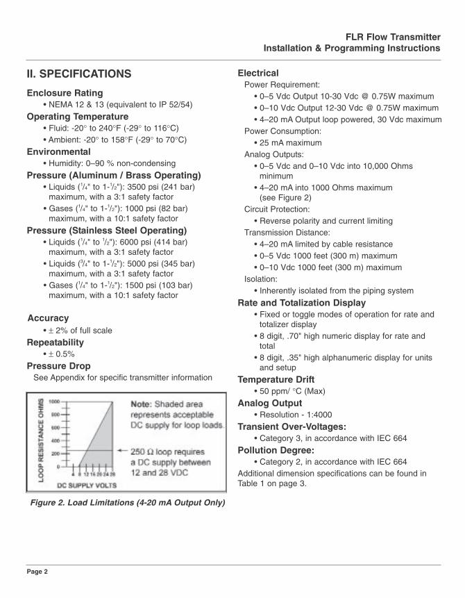
Analog Outputs:• 0–5 Vdc and 0–10 Vdc into 10,000 Ohms
minimum• 4–20 mA into 1000 Ohms maximum
(see Figure 2)Circuit Protection:
• Reverse polarity and current limitingTransmission Distance:
• 4–20 mA limited by cable resistance• 0–5 Vdc 1000 feet (300 m) maximum• 0–10 Vdc 1000 feet (300 m) maximum
Isolation:• Inherently isolated from the piping system
Rate and Totalization Display• Fixed or toggle modes of operation for rate and
totalizer display• 8 digit, .70" high numeric display for rate and
total• 8 digit, .35" high alphanumeric display for units
and setup
Temperature Drift• 50 ppm/ °C (Max)
Analog Output• Resolution - 1:4000
Transient Over-Voltages:• Category 3, in accordance with IEC 664
Pollution Degree:• Category 2, in accordance with IEC 664
Additional dimension specifications can be found inTable 1 on page 3.
FLR Flow TransmitterInstallation & Programming Instructions
Page 2
Figure 2. Load Limitations (4-20 mA Output Only)

Table 1 - Dimensions
III. INSTALLATIONThis unit should be installed and serviced by technically qualified personnel trained in maintaining industrial class flowinstrumentation and processing equipment.
FLR Flow TransmitterInstallation & Programming Instructions
Page 3
A B C D E F G H I J KNominal Length Length Length Width Width Width Width Depth Offset Hole Dia.Port Size in. (mm) in. (mm) in. (mm) in. (mm) in. (mm) in. (mm) in. (mm) in. (mm) in. (mm) in. (mm)
1/4 (SAE 6) 6.60 (168) 5.27 (134) 6.41 (163) 6.00 (152) 3.23 (82) 3.00 (76) 4.20 (107) 2.94 (75) 1.51 (38) .31 (8)
1/2 (SAE 10) 6.60 (168) 5.27 (134) 6.41 (163) 6.00 (152) 3.23 (82) 3.00 (76) 4.20 (107) 2.94 (75) 1.51 (38) .31 (8)
3/4 (SAE 12) 7.20 (183) 5.27 (134) 7.04 (179) 6.00 (152) 3.60 (91) 3.00 (76) 4.20 (107) 2.94 (75) 1.27 (32) .31 (8)
1 (SAE 16) 7.20 (183) 5.27 (134) 7.04 (179) 6.00 (152) 3.60 (91) 3.00 (76) 4.20 (107) 2.94 (75) 1.27 (32) .31 (8)
1-1/4 (SAE 20) 12.20 (310) 10.68 (271) 11.65 (296) 7.63 (194) 4.84 (123) 3.82 (97) 5.02 (128) 4.50 (114) 2.20 (56) .31 (8)
1-1/2 (SAE 24) 12.20 (310) 10.68 (271) 11.65 (296) 7.63 (194) 4.84 (123) 3.82 (97) 5.02 (128) 4.50 (114) 2.20 (56) .31 (8)
Disconnect electrical power before opening wiring enclo-sure. Failure to follow these instructions could result inserious personal injury or death and/or damage to theequipment.
WARNING
This standard transmitter is unidirectional. Attempts to flowfluids in the opposite direction of the flow arrow will result inthe meter acting as a check valve, creating a deadheadingsituation. If the differential pressure magnitude is greatenough, damage to the internal parts of the meter will result.
CAUTION
This transmitter may contain residual amounts of test fluid atthe time of shipment. This fluid should be removed prior toinstallation as the fluid may be incompatible or hazardouswith some liquids or gases. Failure to follow these instructions could result in damage to the equipment.
CAUTION
Air/gas transmitters are NOT oxygen cleaned. Usewith oxygen may cause hazardous or explosive con-ditions that may cause serious personal injury and/orequipment damage.
CAUTION
All wiring should be installed in accordance with theNational Electrical Code and must conform to any applicable state and local codes. Failure to follow theseinstructions could result in serious personal injury or deathand/or damage to the equipment.
WARNING
®
FLR
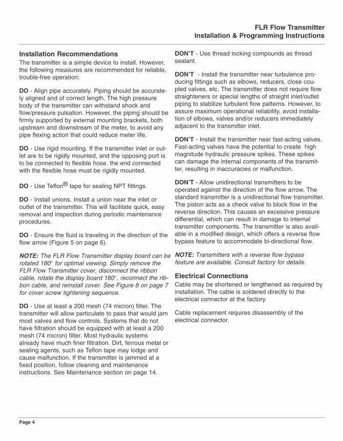
Installation RecommendationsThe transmitter is a simple device to install. However,the following measures are recommended for reliable,trouble-free operation:
DO - Align pipe accurately. Piping should be accurate-ly aligned and of correct length. The high pressurebody of the transmitter can withstand shock andflow/pressure pulsation. However, the piping should befirmly supported by external mounting brackets, bothupstream and downstream of the meter, to avoid anypipe flexing action that could reduce meter life.
DO - Use rigid mounting. If the transmitter inlet or out-let are to be rigidly mounted, and the opposing port isto be connected to flexible hose, the end connectedwith the flexible hose must be rigidly mounted.
DO - Use Teflon® tape for sealing NPT fittings.
DO - Install unions. Install a union near the inlet oroutlet of the transmitter. This will facilitate quick, easyremoval and inspection during periodic maintenanceprocedures.
DO - Ensure the fluid is traveling in the direction of theflow arrow (Figure 5 on page 6).
NOTE: The FLR Flow Transmitter display board can berotated 180° for optimal viewing. Simply remove theFLR Flow Transmitter cover, disconnect the ribboncable, rotate the display board 180°, reconnect the rib-bon cable, and reinstall cover. See Figure 8 on page 7for cover screw tightening sequence.
DO - Use at least a 200 mesh (74 micron) filter. Thetransmitter will allow particulate to pass that would jammost valves and flow controls. Systems that do nothave filtration should be equipped with at least a 200mesh (74 micron) filter. Most hydraulic systemsalready have much finer filtration. Dirt, ferrous metal orsealing agents, such as Teflon tape may lodge andcause malfunction. If the transmitter is jammed at afixed position, follow cleaning and maintenanceinstructions. See Maintenance section on page 14.
DON’T - Use thread locking compounds as threadsealant.
DON’T - Install the transmitter near turbulence pro-ducing fittings such as elbows, reducers, close cou-pled valves, etc. The transmitter does not require flowstraighteners or special lengths of straight inlet/outletpiping to stabilize turbulent flow patterns. However, toassure maximum operational reliability, avoid installa-tion of elbows, valves and/or reducers immediatelyadjacent to the transmitter inlet.
DON’T - Install the transmitter near fast-acting valves. Fast-acting valves have the potential to create highmagnitude hydraulic pressure spikes. These spikescan damage the internal components of the transmit-ter, resulting in inaccuracies or malfunction.
DON’T - Allow unidirectional transmitters to be operated against the direction of the flow arrow. Thestandard transmitter is a unidirectional flow transmitter.The piston acts as a check valve to block flow in thereverse direction. This causes an excessive pressuredifferential, which can result in damage to internaltransmitter components. The transmitter is also avail-able in a modified design, which offers a reverse flowbypass feature to accommodate bi-directional flow.
NOTE: Transmitters with a reverse flow bypass feature are available. Consult factory for details.
Electrical ConnectionsCable may be shortened or lengthened as required byinstallation. The cable is soldered directly to the electrical connector at the factory.
Cable replacement requires disassembly of the electrical connector.
FLR Flow TransmitterInstallation & Programming Instructions
Page 4

SchematicsThe transmitter can be wired in various configurationsto allow interface with many different types of data col-lection and control instrumentation.
Schematics 1 & 2 represent typical wiring for a targetpowered by either AC power or DC supply.Schematics 3 & 4 will be utilized when the flow trans-mitter is operated with loop-powered process indica-tors or data loggers that do not have external sensorexcitation available.
FLR Flow TransmitterInstallation & Programming Instructions
Page 5
Schematic 1: 4-20 mA connection using target power supply
Schematic 2: 0-5 Vdc or 0-10 Vdc connection using target powersupply
Schematic 3: 4-20 mA connection using external power supply
Schematic 4: 0-5 Vdc or 0-10 Vdc connection using externalpower supply
Figure 3. Electrical 4-Pin Connection
Figure 4. Terminology
The flow transmitter is designed to operate only oneof its three outputs at a time (i.e.,0–5 Vdc or 0–10Vdc or 4–20 mA). Connecting multiple outputs simultaneously will result in inaccurate output signallevels.
CAUTION
®

Installing the Transmitter1. Disconnect electrical power from the target sys-
tem before making or changing any transmitterconnections.
2. Use 0.05A fast acting fuse if non-current limitedpower sources are utilized.
3. Terminate cable shield connection at either DCground or Earth ground.
4. Mount the transmitter so fluid is traveling in thedirection of the flow arrow. See Figure 5.
5. Install unit in desired location. Use wrench ontransmitter flats to hold the unit in place duringinstallation. DO NOT TURN the transmitterusing the wrench. See Figure 6.
6. After installation, rotate transmitter by hand toview display. See Figure 7.
7. Capture the zero flow position on the metercone using the ZERO CAPTURE procedurefound on page 12.
IV. OPERATION
NOTE: Refer to the Appendix for application informa-tion and fluid charts.
Operating the MeterThe monitor has two modes of operation, referred toas RUN mode and PROGRAM mode as indicated onthe display screen readout. Normal operation will be inthe run mode. To access the program mode, press theMENU key until the first programming screen DISPLAY appears. (PROGRAM appears on left side of
display.) After programming the meter a password maybe entered to prevent unauthorized access or chang-ing of the setup features.
Normal Operation (RUN) ModeDuring normal operation, the display will show RUNand the flow rate, total flow, or toggle back and forthbetween the two as defined by the DISPLAY configu-ration.
The 4 buttons have the following function in RUNmode:
MENU - Selects programming mode.
UP ARROW - No function.
RIGHT ARROW - No function.
FLR Flow TransmitterInstallation & Programming Instructions
Page 6
Figure 5. Flow Direction Arrow
Place wrench ontransmitter flats on thesame side plumbing is
being tightened
Never place wrenchon transmitter flatsopposite plumbing
being tightened
Figure 6. Installing Transmitter
Never use wrench torotate transmitter
body when viewingflow display
Rotate transmitter byhand to view flow
display
Figure 7. Rotating Transmitter
FLOWINLET PORT
FLR

ENTER - The current total can be manually stored inthe monitor's flash memory. Press and hold theENTER key for 2 seconds. The display will respondwith a flashing TOTALSVD and then will return to RUNmode.
RESET TOTAL - To reset the monitor total display,press the MENU and ENTER keys simultaneouslyuntil TOTALRST starts to flash. The TOTALRST willstop flashing and the display will return to RUN modeat the conclusion of the reset procedure.
Programming Operation (PROGRAM) ModeThe programming mode allows the user to change theconfiguration and adjust the calibration of the meter.The FLR Flow Transmitter has two types of configura-tion changes in program mode:
• To view or change selections from a predefined list
• To view or change numeric entriesDuring programming operation, the following four but-ton functions are provided:
MENU - Enters and exits programming mode.
Change to programming mode by pressing the MENUkey once. The mode indicator on the display willchange from RUN to PROGRAM.
UP ARROW - Use the UP ARROW key to scrollthrough the configuration choices in a bottom-to-toporder. For numeric setup, this button incrementsnumeric values.
RIGHT ARROW - Use the RIGHT ARROW key toscroll through the configuration choices in a top-to-bot-tom order. For numeric setup, this button moves theactive digit to the right.
ENTER - Used to enter menus to change configura-tions and to save programming information.
NOTE: If any input value exceeds the meter's capabili-ties the LIMIT indicator will begin to flash indicating aninvalid entry. Press ENTER once to return to the entryscreen to reenter the value.
Cover Removal/Reinstallation
It is necessary to remove the FLR Transmitter cover toaccess the programming keys. Use a Phillips screw-driver to remove the 4 screws that hold the cover inplace, turning them counterclockwise. When program-ming is completed, reinstall the cover. To properly seatthe built-in cover gasket, tighten the cover screwsclockwise in a criss-cross pattern as shown in Figure 8.
Figure 8. Cover Screw Tightening Sequence
FLR Flow TransmitterInstallation & Programming Instructions
Page 7
®

Programming Procedures
The FLR Transmitter allows two basic sets of program-ming procedures: list item selection and enteringnumeric values.
List Item Selection Procedure
Note: If you are already in PROGRAM mode and theselection to be viewed or changed is already displayed, proceed to step 3 below. If you are in PROGRAM mode and the selection to be viewed orchanged is not displayed, press the UP or RIGHTARROW key and repeat pressing until the desiredselection appears. Proceed to step 3.
1. Press MENU.
PROGRAM appears in the lower left-hand corner and DISPLAY appears.
2. Press the UP ARROW or RIGHT ARROW keyto move to the desired selection.
3. Press ENTER to view the current selection.
4a. If the current selection is desired, press ENTERto confirm.
The unit will automatically advance.
4b. If current selection must change, press eitherarrow key to scroll through the available choic-es. Press ENTER to confirm your selection.
The unit will automatically advance.
5. To exit programming, press the MENU button.
The display will change to RUN mode.
Numeric Value Entry Procedure
Note: If you are already in PROGRAM mode and thedesired selection is displayed, proceed to step 3below. If you are in PROGRAM mode and the desiredselection is not displayed, press the UP or RIGHTARROW key and repeat pressing until the desiredselection appears. Proceed to step 3.
1. Press MENU.
PROGRAM appears in the lower left-hand corner andDISPLAY appears.
2. Press UP or RIGHT ARROW key until thedesired selection displays.
The current numeric value for this selection appears inthe upper section of the display.
3a. If the current displayed value is desired, pressENTER. The left most programmable numberbegins to flash. Press ENTER again to confirmand keep the current setting.
The unit will automatically advance.
3b. If current selection must change, press ENTER.The left most programmable number begins toflash. Use the UP ARROW key to scroll throughthe digits 0–9 and change the flashing digit tothe desired value. Use the RIGHT ARROW keyto move the active digit to the right. Continueusing the UP and RIGHT ARROW keys until alldesired digits are selected.
4. Press ENTER to confirm your selection.
The unit will automatically advance.
5. To exit programming mode, press the MENUkey.
The display will change to RUN mode.
FLR Flow TransmitterInstallation & Programming Instructions
Page 8
Programming Flow ChartThe programming flow chart on pages 10 and 11 willaid understanding of the menu structure of the FLRFlow Transmitter. It will also help with understandingthe available configuration selections.
Programming Descriptions
Display Mode
The meter can display RATE (flow rate) or TOTAL(total accumulated flow) or alternate between BOTHrate and total. Its displayed name is DISPLAY and isviewed or changed using the List Item SelectionProcedure found on page 8.
Rate Units of Measure
The meter allows the selection of many common rateunits. Its displayed name is RATE UNT and is viewedor changed using the List Item Selection Procedurefound on page 8.
Rate (Time) Interval
The meter allows selection of several intervals basedon time. Its displayed name is RATE INT and isviewed or changed using the List Item SelectionProcedure found on page 8.
Total Units of Measure
If the total flow is being displayed, the units for thetotal must first be chosen. The monitor allows thechoice of many common totalization units. Its displayed name is TOTL UNT and is viewed orchanged using the List Item Selection Procedurefound on page 8.
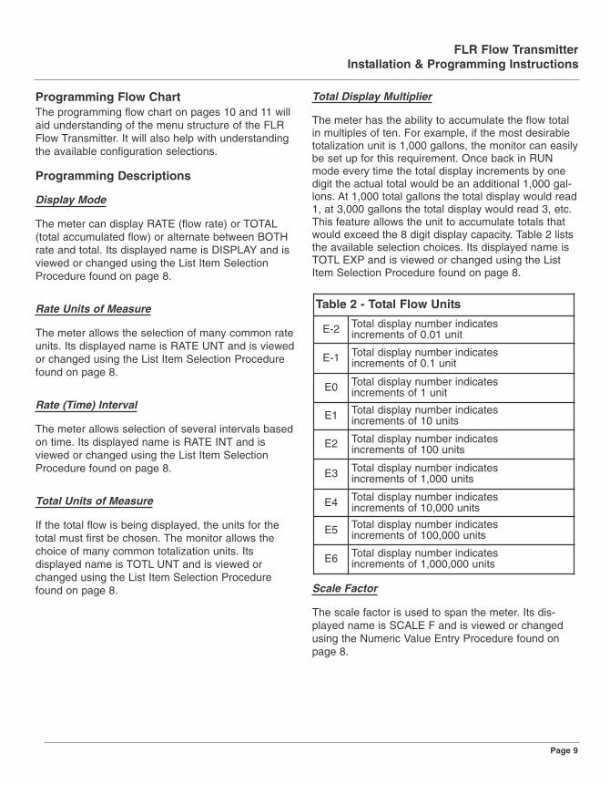
Total Display Multiplier
The meter has the ability to accumulate the flow totalin multiples of ten. For example, if the most desirabletotalization unit is 1,000 gallons, the monitor can easilybe set up for this requirement. Once back in RUNmode every time the total display increments by onedigit the actual total would be an additional 1,000 gal-lons. At 1,000 total gallons the total display would read1, at 3,000 gallons the total display would read 3, etc.This feature allows the unit to accumulate totals thatwould exceed the 8 digit display capacity. Table 2 liststhe available selection choices. Its displayed name isTOTL EXP and is viewed or changed using the ListItem Selection Procedure found on page 8.
Scale Factor
The scale factor is used to span the meter. Its dis-played name is SCALE F and is viewed or changedusing the Numeric Value Entry Procedure found onpage 8.
Table 2 - Total Flow Units
E-2 Total display number indicatesincrements of 0.01 unit
E-1 Total display number indicatesincrements of 0.1 unit
E0 Total display number indicatesincrements of 1 unit
E1 Total display number indicatesincrements of 10 units
E2 Total display number indicatesincrements of 100 units
E3 Total display number indicatesincrements of 1,000 units
E4 Total display number indicatesincrements of 10,000 units
E5 Total display number indicatesincrements of 100,000 units
E6 Total display number indicatesincrements of 1,000,000 units
FLR Flow TransmitterInstallation & Programming Instructions
Page 9

FLR Flow TransmitterInstallation & Programming Instructions
Page 10

FLR Flow TransmitterInstallation & Programming Instructions
Page 11

FLR Flow TransmitterInstallation & Programming Instructions
Page 12
Zero Capture
The zero position of the meter cone must be set wheninstalling the meter. To capture the zero calibrationposition, press ENTER at the ZERO CAP prompt. NOwill display. Press either arrow key to change to YES,then press ENTER to capture zero.
Meter Type
The meter can be programmed to compensate forspecific gravity, pressure, and temperature dependingupon the application. Its displayed name is METER-TYP and is viewed or changed using the List ItemSelection Procedure found on page 8.
Note: Refer to Flow Chart on pages 10 and 11. WhenMeter Type WATER is selected, specific gravity (SP GRAV) will automatically follow.
Note: Refer to Flow Chart on pages 10 and 11. WhenMeter Type OIL is selected, meter size (METERSIZ),viscosity (VISC SUS), and specific gravity (SP GRAV)will automatically follow.
Note: Refer to Flow Chart on pages 10 and 11. WhenMeter Type GAS is selected, operating pressure (OPPRESS ), operating temperature (OP TEMP), andspecific gravity (SP GRAV) will automatically follow.
Meter Size
Meter size is used in conjunction with Viscosity to perform viscosity correction. Table 3 lists the availableselection choices. Its displayed name is METERSIZand is viewed or changed using the List Item SelectionProcedure found on page 8.
Viscosity
Viscosity is used in conjunction with the Meter Size toperform viscosity correction when the Meter typeselected is OIL. Enter in SUS units the viscosity of theoil that will be used. Its displayed name is VISC SUSand is viewed or changed using the Numeric ValueEntry Procedure found on page 8.
Operating Pressure
The operating pressure is used in gas applications tocompensate for the actual pressure being measuredat the meter. Enter the operating pressure in PSI units.Its displayed name is OP PRES and is viewed orchanged using the Numeric Value Entry Procedurefound on page 8.
Operating Temperature
The operating temperature is used in gas applicationsto compensate for the actual temperature of the gasbeing measured at the meter. Enter the operating temperature in ºF units. Its displayed name is OPTEMP and is viewed or changed using the NumericValue Entry Procedure found on page 8.
Specific Gravity Correction Factor
Specific Gravity is used to compensate for the specificgravity of the liquid or gas being measured with themeter. Its displayed name is SP GRAV and is viewedor changed using the Numeric Value Entry Procedurefound on page 8.
Damping
The Damping factor is increased to enhance the stability of the flow readings. Damping values aredecreased to allow the flow meter to react faster tochanging values of flow.This parameter can rangefrom 0 to 99; factory default is 0. Its displayed name isDAMPING and is viewed or changed using theNumeric Value Entry Procedure found on page 8.
1/4" & 1/2" meter 11/4" & 11/2" meter3/4" & 1" meter
1GPM 30GPM2GPM
2GPM 50GPM5GPM
5GPM 75GPM10GPM
10GPM 100GPM20GPM
15GPM 150GPM30GPM
Table 3 - Meter Size Types

Output Mode
The FLR Flow Transmitter offers three analog outputmodes:
• 4–20 mAOutput Signal • 0–5 Volts DC Output Signal • 0–10 Volts DC Output Signal
The output mode selected is determined by the type ofperipheral device being connected to the FLR FlowTransmitter.
The displayed name is OUT MODE and is viewed orchanged using the List Item Selection Procedurefound on page 8.
Note: Setup prompts and descriptors for configuringand calibrating the analog output will correspond tothe output mode selected. Refer to the Flow Chart onpages 10 and 11.
Flow at 0V or 4mA Setting
This selection is used to configure the minimum ana-log output signal to the corresponding flow rate. Enterthe flow rate at which the minimum analog output sig-nal is required using the Numeric Value EntryProcedure found on page 8.
Flow at 5V, 10V or 20mA Setting
This selection is used to configure the maximum ana-log output signal to the corresponding flow rate. Enterthe flow rate at which the maximum analog output sig-nal is required using the Numeric Value EntryProcedure found on page 8.
Calibration of Analog Output
This selection allows access to the calibration andtesting of the analog output signal. Calibration of theAnalog Output is preset at the factory, but can bechanged to customize calibration for your installation.
To test or change the analog output calibration, it isfirst necessary to change the default setting for CALOUT? from NO to YES.
Note: Setup prompts and descriptors for configuringand calibrating the analog output will correspond tothe output mode selected. Refer to the Flow Chart onpages 10 and 11.
1. At the CAL OUT? prompt press ENTER.NO will display.
2. To change to YES, press either arrow key.
3. The analog output will go to its minimum outputlevel. A numeric value between 0–4000 will dis-play. This is an internal number used to drivethe analog output.
4. To increase the analog output signal level, pressthe UP ARROW key. To decrease the analogoutput signal level, press the RIGHT ARROWkey.
5. Press ENTER to store the setting.
6. The analog output will go to its maximum outputlevel. A numeric value between 0–4000 will dis-play. This is an internal number used to drivethe analog output.
7. To increase the analog output signal level, pressthe UP ARROW key. To decrease the analogoutput signal level, press the RIGHT ARROWkey.
8. Press ENTER to store the setting.
9. The unit will advance to the analog output testmode. The analog output will go to its minimumoutput level. A numeric value of 0 will display.For test purposes, the analog output signal canbe run up or down in increments of 1 milliamp or1 volt, depending on the OUT MODE selected.
10. To increase the analog output signal level, pressthe UP ARROW key. To decrease the analogoutput signal level, press the RIGHT ARROWkey.
11. Press ENTER to exit the analog calibrationmode.
12. The unit automatically advances to the PASS-WORD feature.
FLR Flow TransmitterInstallation & Programming Instructions
Page 13

Password
Password protection prevents unauthorized users fromchanging programming information. Initially the pass-word is set to all zeros. Its displayed name is PASSWORD and is viewed or changed using theNumeric Value Entry Procedure found on page 8.
Restore Defaults
This feature allows you to restore factory calibrationdata. Its displayed name is RES DFLT. To restore fac-tory calibration data, select YES, then press ENTER.
V. MAINTENANCE
Cartridge Cleaning (Figure 4 on page 5 and Figure 9 on page 15)
1. Disconnect the transmitter cable.
2. Remove the transmitter from the line. Removeexcess piping from transmitter.
NOTE: It is not necessary to remove the aluminumhousing from the transmitter to remove it from the line.
3. Thoroughly wipe off the entire transmitter sur-face using mild detergent or isopropyl alcohol.
4. Remove the inlet port cap, wave spring, retain-ing ring, and cone assembly from the transmitterbody (Figure 9 on page 15).
5. Gently push the body towards the outlet port.
6. The piston, inner magnet and transmitter springare secured within the transmitter body with aretaining ring. Remove the retaining ring with asmall screwdriver, then the internal componentscan be removed from the body (Figure 9 onpage 15).
NOTE: If internal parts do not slide freely from cartridge, use a wooden dowel inserted into the outletport of the transmitter to push parts out.
7. Place all parts on a clean work surface. Cleanand inspect all parts. Replace any that appearworn or damaged.
Check inlet port O-ring for damage and replaceif required.
8. Reassemble the transmitter by inserting thetransmitter spring into the body, followed by thepiston/inner magnet assembly. A slight compres-sion of the piston against the spring is requiredduring installation of the retaining ring.
9. Gently push body assembly into the outlet endof the transmitter enclosure. The flat surface ofthe body outlet port should be flush with thetransmitter enclosure opening.
10. With the transmitter positioned vertically on aflat surface, inlet port facing up, install the trans-mitter cone assembly and wave spring into thebody and secure with the inlet port end cap.
11. Reinstall transmitter to the line. Reconnect elec-trical power.
FLR Flow TransmitterInstallation & Programming Instructions
Page 14
Before attempting to remove the transmitter from theline, check the system to confirm that line pressurehas been reduced to zero PSI. Failure to followthese instructions could result in serious personalinjury or death and/or damage to the equipment.
WARNING
Always disconnect the primary power source beforeopening the enclosure for inspection or service.Failure to follow these instructions could result inserious personal injury or death and/or damage tothe equipment.
WARNING
Do not use aromatic hydrocarbons, halogenatedhydrocarbons, ketones, or ester based fluids on polycarbonate lens. Failure to follow these instructions could result in damage to the transmitter.
WARNING

Inspection1. Frequent inspection should be made. The envi-
ronment and frequency of use should determinea schedule for maintenance checks. It is recom-mended that it should be at least once a year.
2. Perform visual, electrical, and mechanicalchecks on all components on a regular basis.
3. Visually check for undue heating evidence suchas discoloration of wires or other components,damaged or worn parts, or leakage evidencesuch as water or corrosion in the interior.
4. Electrically check to make sure that all connec-tions are clean and tight and that the device iswired properly.
VI. TROUBLESHOOTING
No LCD display• For 4–20 mA operation, check for current flow in
the loop.• Check polarity of the current loop connections
for proper orientation.• For 0–5 V or 0–10 V operation, check for proper
voltage being supplied to the unit.• Check polarity of the supply voltage.
No rate or total displayed• Check flow meter cone for debris. Cone should
move inside the tube freely.• Check setup programming of flow meter.
Unstable Flow Reading• This usually indicates pulsing or oscillation in the
actual flow. Increase the DAMPING parameterto increase the filtering in order to provide amore stable display reading.
VII. APPENDIXApplication Information – LiquidViscosity Effect (SUS/cSt)The design utilizes a precision machined, sharp-edgedorifice and biasing calibration spring that assuresoperating stability and accuracy over the wide viscosi-ty range common to many fluids. Generally, high flow
models of each transmitter size provide good accuracyover a viscosity range of 40 to 500 SUS (4.2 to 109cSt).
Density Effect (specific gravity)Any fluid density change from stated standards has aproportionate effect on transmitter accuracy.Corrections for more or less dense fluids can be madeto standard scales using the following correction fac-tor:
for water/water-based transmitters
for petroleum-based transmitters0.876
Specific Gravity
1.0Specific Gravity
FLR Flow TransmitterInstallation & Programming Instructions
Page 15
Figure 9. Cartridge Components
0.876Specific Gravity
1.0Specific Gravity
0.876
Specific Gravity
1.0
Specific Gravity
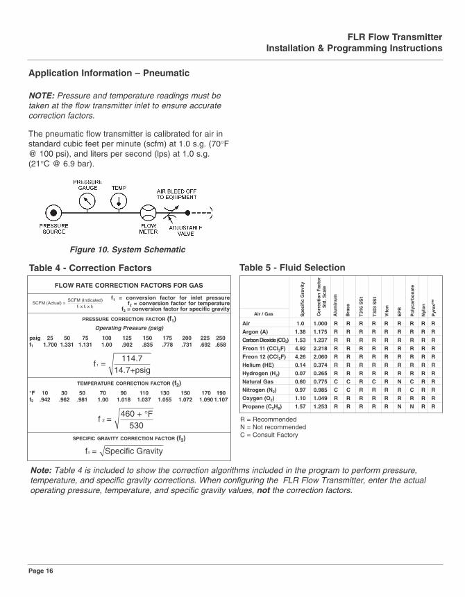
Application Information – Pneumatic
NOTE: Pressure and temperature readings must betaken at the flow transmitter inlet to ensure accuratecorrection factors.
The pneumatic flow transmitter is calibrated for air instandard cubic feet per minute (scfm) at 1.0 s.g. (70°F@ 100 psi), and liters per second (lps) at 1.0 s.g.(21°C @ 6.9 bar).
FLR Flow TransmitterInstallation & Programming Instructions
Page 16
Figure 10. System Schematic
Air 1.0 1.000 R R R R R R R R R
Argon (A) 1.38 1.175 R R R R R R R R R
Carbon Dioxide (CO2) 1.53 1.237 R R R R R R R R R
Freon 11 (CCI3F) 4.92 2.218 R R R R R R R R R
Freon 12 (CCI2F) 4.26 2.060 R R R R R R R R R
Helium (HE) 0.14 0.374 R R R R R R R R R
Hydrogen (H2) 0.07 0.265 R R R R R R R R R
Natural Gas 0.60 0.775 C C R C R N C R R
Nitrogen (N2) 0.97 0.985 C C R R R R C R R
Oxygen (O2) 1.10 1.049 R R R R R R R R R
Propane (C3H8) 1.57 1.253 R R R R R N N R R
Air / Gas
ytivarG ci fic e
pS
mu
nim
ulA
tS
S 613T
tS
S 303T
noti
V
RP
E
ro tca
F n
oitcerro
C elac
S .d t
S s sarB
etan
obracyl
oP
noly
N
™x eryP
R = RecommendedN = Not recommendedC = Consult Factory
FLOW RATE CORRECTION FACTORS FOR GAS
SCFM (Actual) = SCFM (Indicated)
f x f x f1 2 3
f1 = conversion factor for inlet pressuref2 = conversion factor for temperature
f3 = conversion factor for specific gravity
PRESSURE CORRECTION FACTOR (f1)Operating Pressure (psig)
psig 25 50 75 100 125 150 175 200 225 250f1 1.700 1.331 1.131 1.00 .902 .835 .778 .731 .692 .658
f =114.7
14.7+psig1
TEMPERATURE CORRECTION FACTOR (f2)
°F 10 30 50 70 90 110 130 150 170 190f2 .942 .962 .981 1.00 1.018 1.037 1.055 1.072 1.090 1.107
f 2 =460 + °F
530SPECIFIC GRAVITY CORRECTION FACTOR (f3)
f = Specific Gravity 3
Table 4 - Correction Factors Table 5 - Fluid Selection
Note: Table 4 is included to show the correction algorithms included in the program to perform pressure,temperature, and specific gravity corrections. When configuring the FLR Flow Transmitter, enter the actual operating pressure, temperature, and specific gravity values, not the correction factors.

FLR Flow TransmitterInstallation & Programming Instructions
Page 17
Water Based Fluids
FLOW, GPM
IS
P ,PO
RD
ER
US
SE
RP
1/4"
.02-.20.05-.50
.10-1.0
.20-2.0
FLOW, GPM
IS
P ,PO
RD
ER
US
SE
RP
1/2"1-15
1-10
0.2-2.00.1-1.00.5-5.0
FLOW, GPM
IS
P ,PO
RD
ER
US
SE
RP
3/4" / 1"
0.5
4-4
3-30
2-20
FLOW, GPM
IS
P ,PO
RD
ER
US
SE
RP
1-1/4"/ 1-1/2" 10-150
10-100
10-75
5-50
3-30
FLOW, GPM
DIS
P ,LAIT
NE
REFFI
D E
RU
SS
ER
P
3" 20-275
20-180
Flow vs. Pressure Drop
FLOW, GPM
IS
P ,PO
RD
ER
US
SE
RP
1/2" Reverse Flow
0.1-1.00.5-5.0
0.2-2.0
1-10
1-15
FLOW, GPM
IS
P ,PO
RD
ER
US
SE
RP
3/4"/1" Reverse Flow
0.2-2.00.5-5.0
1-10
2-20
3-30
4-40
FLOW, GPM
IS
P ,PO
RD
ER
US
SE
RP
1-1/4"/1-1/2" Reverse Flow
3-305-50
10-75
10-100
10-150
Water Based Fluids (continued)

FLR Flow TransmitterInstallation & Programming Instructions
Water
FLOW, GPM
IS
P ,PO
RD
ER
US
SE
RP
1/4"
.02-.20.05-.50
.10-1.0
.20-2.0
FLOW, GPM
IS
P ,PO
RD
ER
US
SE
RP
1/2"1-15
1-10
0.2-2.00.1-1.00.5-5.0
FLOW, GPM
IS
P ,PO
RD
ER
US
SE
RP
3/4" / 1"
0.5-5.0
0.2-2.0
1-10
5-50
4-40
3-30
2-20
FLOW, GPM
IS
P ,PO
RD
ER
US
SE
RP
1-1/4"/ 1-1/2" 10-150
10-100
10-75
5-50
3-30
FLOW, GPM
IS
P ,PO
RD
ER
US
SE
RP
3" 15-150
10-100
5-50
Caustic and Corrosive Liquids
FLOW, GPM
IS
P ,PO
RD
ER
US
SE
RP
1/4".10-1.0
.20-2.0
FLOW, GPM
IS
P ,PO
RD
ER
US
SE
RP
1/2"1-15
1-10
0.2-2.00.5-5.0
FLOW, GPM
IS
P ,PO
RD
ER
US
SE
RP
3/4" / 1"
0.5-5.0
0.1-2.0
1-10
4-40
3-30
2-20
FLOW, GPM
IS
P ,P
OR
D E
RU
SS
ER
P
1-1/4"/ 1-1/2"
10-100
10-75
5-50
3-30
1/4" 1/2"
Page 18
FLR Flow TransmitterInstallation & Programming Instructions
Page 19
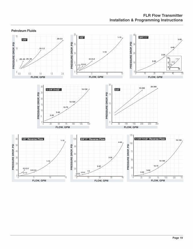
Petroleum Fluids
FLOW, GPM
IS
P ,PO
RD
ER
US
SE
RP
1/4" .20-2.0
.10-1.0
.05-.50.02-.20
FLOW, GPM
IS
P ,PO
RD
ER
US
SE
RP
1/2" 1-15
1-10
0.5-5.0
0.2-2.00.1-1.0
FLOW, GPM
IS
P ,PO
RD
ER
US
SE
RP
3/4"/ 1"5-50
4-40
3-30
2-20
00
5
10
10
1-10
0.5-5.0
0.2-2.0
FLOW, GPM
IS
P ,PO
RD
ER
US
SE
RP
1-1/4"/1-1/2" 10-150
10-100
10-75
5-50
3-30
FLOW, GPM
IS
P ,PO
RD
ER
US
SE
RP
3.0"20-300
10-200
FLOW, GPM
IS
P ,PO
RD
ER
US
SE
RP
1/2" Reverse Flow
0.1-1.00.5-5.0
0.2-2.0
1-10
1-15
FLOW, GPM
IS
P ,PO
RD
ER
US
SE
RP
3/4"/1" Reverse Flow
0.2-2.00.5-5.0
1-10
2-20
3-30
4-40
FLOW, GPM
IS
P ,PO
RD
ER
US
SE
RP
1-1/4"/1-1/2" Reverse Flow
3-305-50
10-75
10-100
10-150

FLR Flow TransmitterInstallation & Programming Instructions
Page 20
Phosphate Ester
FLOW, GPM
IS
P ,PO
RD
ER
US
SE
RP
1/4".20-2.0
.10-1.0
0.00
2
4
6
0.5
.05-.5O.02-.20
FLOW, GPM
IS
P ,PO
RD
ER
US
SE
RP
1/2" 1-15
1-10
0.5-5.0
0 1 2 2.50
2
40.2-2.0
0.1-1.0
FLOW, GPM
IS
P ,PO
RD
ER
US
SE
RP
1-1/4" / 1-1/2" 10-150
10-100
10-75
5-50
3-30
FLOW, GPM
IS
P ,PO
RD
ER
US
SE
RP
3/4"/ 1"
2-20
3-30
5-50
4-40
1-10
0 1 2 3 540
2
4
6
0.2-2.0
0.5-5.0
FLOW, GPM
IS
P ,PO
RD
ER
US
SE
RP
1/2" Reverse Flow
0.1-1.00.5-5.0
0.2-2.0
1-10
1-15
FLOW, GPM
IS
P ,PO
RD
ER
US
SE
RP
3/4"/1" Reverse Flow
0.2-2.00.5-5.0
1-10
2-20
3-30
4-40
FLOW, GPM
IS
P ,PO
RD
ER
US
SE
RP
1-1/4"/1-1/2" Reverse Flow
3-305-50
10-75
10-100
10-150

FLOW, SCFM
IS
P ,PO
RD
ER
US
SE
RP
1/4"3-30
2-20
FLOW, SCFM
IS
P ,PO
RD
ER
US
SE
RP
1/2"
10-100
5-50
2-25
15-150
FLOW, SCFM
IS
P ,PO
RD
ER
US
SE
RP
3/4"/1"
15-150
10-100
5-25
5-50
25-250
FLOW, SCFM
1-1/4"/1-1/2"
20-200
40-400
60-600
80-800
100-1000
IS
P ,PO
RD
ER
US
SE
RP
FLR Flow TransmitterInstallation & Programming Instructions
Page 21
A.P.I. Oil
FLOW, GPM
IS
P ,PO
RD
ER
US
SE
RP
1/2" 1-15
1-10
0.5-5.0
0.2-2.0
FLOW, GPM
IS
P ,PO
RD
ER
US
SE
RP
3/4"/ 1"
4-40
3-30
2-201-10
0.5-5.0
0.2-2.0
FLOW, GPM
IS
P ,PO
RD
ER
US
SE
RP
1-1/4"/1-1/2"
10-100
10-75
5-50
3-30
FLOW, GPM
IS
P ,PO
RD
ER
US
SE
RP
1/4"
.10-1.0
.20-2.0
Air / Caustic and Corrosive Gases

FLR Flow TransmitterInstallation & Programming Instructions
Page 22
Air / Compressed Gases
FLOW, SCFM
DISP ,LAITNEREF FID ERUSSERP
100-1400 200-22003"
FLOW, SCFM
IS
P ,PO
RD
ER
US
SE
RP
1/4"3-30
2-20
1-10
0.5-5
FLOW, SCFM
IS
P ,PO
RD
ER
US
SE
RP
1/2"
10-100
5-50
2-25
15-150
FLOW, SCFM
IS
P ,PO
RD
ER
US
SE
RP
3/4"/1"
15-150
10-100
5-25
5-50
25-250
FLOW, SCFM
1-1/4"/1-1/2"
20-200
40-400
60-600
80-800
100-1000
IS
P ,PO
RD
ER
US
SE
RP

FLR Flow TransmitterInstallation & Programming Instructions
NOTES:
Page 23

FLR Flow TransmitterInstallation & Programming Instructions
NOTES:
Page 24

FOR WARRANTY RETURNS, please have thefollowing information available BEFORE contactingOMEGA:1. Purchase Order number under which the
product was PURCHASED,2. Model and serial number of the product under
warranty, and3. Repair instructions and/or specific problems
relative to the product.
FOR NON-WARRANTY REPAIRS, consultOMEGA for current repair charges. Have thefollowing information available BEFORE con-tacting OMEGA:1. Purchase Order number to cover the COST
of the repair,2. Model and serial number of the product, and3. Repair instructions and/or specific
problems relative to the product.
OMEGA’s policy is to make running changes, not model changes, whenever an improvement is possible. This affords ourcustomers the latest in technology and engineering.OMEGA is a registered trademark of OMEGA ENGINEERING, INC.© Copyright 2005 OMEGA ENGINEERING, INC. All rights reserved. This document may not be copied, photocopied, reproduced,translated, or reduced to any electronic medium or machine-readable form, in whole or in part, without the prior written consent ofOMEGA ENGINEERING, INC.
WARRANTY/ DISCLAIMEROMEGA ENGINEERING, INC. warrants this unit to be free of defects in materials and workmanshipfor a period of 13 months from date of purchase. OMEGA’s Warranty adds an additional one (1)month grace period to the normal one (1) year product warranty to cover handling and ship-ping time. This ensures that OMEGA’s customers receive maximum coverage on each product. If the unit malfunctions, it must be returned to the factory for evaluation. OMEGA’s CustomerService Department will issue an Authorized Return (AR) number immediately upon phone or writ-ten request. Upon examination by OMEGA, if the unit is found to be defective, it will be repaired orreplaced at no charge. OMEGA’s WARRANTY does not apply to defects resulting from any actionof the purchaser, including but not limited to mishandling, improper interfacing, operation outsideof design limits, improper repair, or unauthorized modification. This WARRANTY is VOID if theunit shows evidence of having been tampered with or shows evidence of having been damaged asa result of excessive corrosion; or current, heat, moisture or vibration; improper specification; mis-application; misuse or other operating conditions outside of OMEGA’s control. Components inwhich wear is not warranted, include but are not limited to contact points, fuses, and triacs.OMEGA is pleased to offer suggestions on the use of its various products. However,OMEGA neither assumes responsibility for any omissions or errors nor assumesliability for any damages that result from the use of its products in accordance withinformation provided by OMEGA, either verbal or written. OMEGA warrants only thatthe parts manufactured by the company will be as specified and free of defects.OMEGA MAKES NO OTHER WARRANTIES OR REPRESENTATIONS OF ANY KINDWHATSOEVER, EXPRESSED OR IMPLIED, EXCEPT THAT OF TITLE, AND ALL IMPLIEDWARRANTIES INCLUDING ANY WARRANTY OF MERCHANTABILITY AND FITNESS FORA PARTICULAR PURPOSE ARE HEREBY DISCLAIMED. LIMITATION OF LIABILITY: Theremedies of purchaser set forth herein are exclusive, and the total liability of OMEGAwith respect to this order, whether based on contract, warranty, negligence,indemnification, strict liability or otherwise, shall not exceed the purchase price of thecomponent upon which liability is based. In no event shall OMEGA be liable forconsequential, incidental or special damages.CONDITIONS: Equipment sold by OMEGA is not intended to be used, nor shall it be used: (1) as a“Basic Component” under 10 CFR 21 (NRC), used in or with any nuclear installation or activity; or(2) in medical applications or used on humans. Should any Product(s) be used in or with anynuclear installation or activity, medical application, used on humans, or misused in any way,OMEGA assumes no responsibility as set forth in our basic WARRANTY/ DISCLAIMER language,and, additionally, purchaser will indemnify OMEGA and hold OMEGA harmless from any liabilityor damage whatsoever arising out of the use of the Product(s) in such a manner.
RETURN REQUESTS/ INQUIRIESDirect all warranty and repair requests/inquiries to the OMEGA Customer Service Department. BEFORERETURNING ANY PRODUCT(S) TO OMEGA, PURCHASER MUST OBTAIN AN AUTHORIZED RETURN(AR) NUMBER FROM OMEGA’S CUSTOMER SERVICE DEPARTMENT (IN ORDER TO AVOID PRO-CESSING DELAYS). The assigned AR number should then be marked on the outside of the returnpackage and on any correspondence. The purchaser is responsible for shipping charges, freight, insur-ance and proper packaging to prevent breakage in transit.

Where Do I Find Everything I Need for Process Measurement and Control?
OMEGA…Of Course!Shop online at omega.com
M4183/0405
TEMPERATURE�� Thermocouple, RTD & Thermistor
Probes, Connectors, Panels &Assemblies
�� Wire: Thermocouple, RTD &Thermistor
�� Calibrators & Ice Point References�� Recorders, Controllers & Process
Monitors�� Infrared Pyrometers
PRESSURE, STRAIN AND FORCE�� Transducers & Strain Gages�� Load Cells & Pressure Gages�� Displacement Transducers�� Instrumentation & Accessories
FLOW/LEVEL�� Rotameters, Gas Mass Flowmeters &
Flow Computers�� Air Velocity Indicators�� Turbine/Paddlewheel Systems�� Totalizers & Batch Controllers
pH/CONDUCTIVITY�� pH Electrodes, Testers & Accessories�� Benchtop/Laboratory Meters�� Controllers, Calibrators, Simulators &
Pumps�� Industrial pH & Conductivity
Equipment
DATA ACQUISITION�� Data Acquisition & Engineering
Software�� Communications-Based Acquisition
Systems�� Plug-in Cards for Apple, IBM &
Compatibles�� Datalogging Systems�� Recorders, Printers & Plotters
HEATERS�� Heating Cable�� Cartridge & Strip Heaters�� Immersion & Band Heaters�� Flexible Heaters�� Laboratory Heaters
ENVIRONMENTALMONITORING AND CONTROL�� Metering & Control Instrumentation�� Refractometers�� Pumps & Tubing�� Air, Soil & Water Monitors�� Industrial Water & Wastewater
Treatment�� pH, Conductivity & Dissolved Oxygen
Instruments