Embed Size (px)
Citation preview
1
The premier source of parts and accessories for mini lathes and mini mills.
Shooting Star DRO Installation Instructions The CBX Digital Position Readout is a low-cost digital readout system that works great on the mini mill. It can be mounted on the mini mill so that it does not get in the way of normal use of the mini mill.
CBX Digital Position Readout can be installed in conjunction with the Mini Mill Power Feed (LittleMachineShop.com part number 1905). A thin mounting bracket that fits between the power feed motor and the mini mill table is used.
Additional Hardware Besides the hardware that comes with the CBX Digital Position Readout, you will need the following:
• Two 8-32 x ½” socket head cap screws • Two ¼-20 x ¾” socket head cap screws • Two ¼” SAE flat washers • One M6 x 20 socket head cap screws* • Two #6-32 x 3/8” socket head cap screws** • Two 10-32 x 1¼” socket head cap screws • Four 10-32 x ½” flat head socket screws • Four 8-32 x ¼” self-locking dog point socket set screws
This hardware is included when you purchase your Shooting Star DRO from LittleMachineShop.com.
You will also need some split wire loom and about 10 plastic cable ties. We used about 4 feet of 1/2” split wire loom and 2 feet of 3/8” split wire loom.
Tools You will need the following tools to install the DRO.
• Hex wrenches, both inch and metric • A set of transfer punches • An electric hand drill • A 1/4”–20 NC tap and #7 tap drill • A #10–32 NF tap and #21 tap drill • A #8–32 NC tap and #29 tap drill • A #6–32 NC tap and #36 tap drill**
2
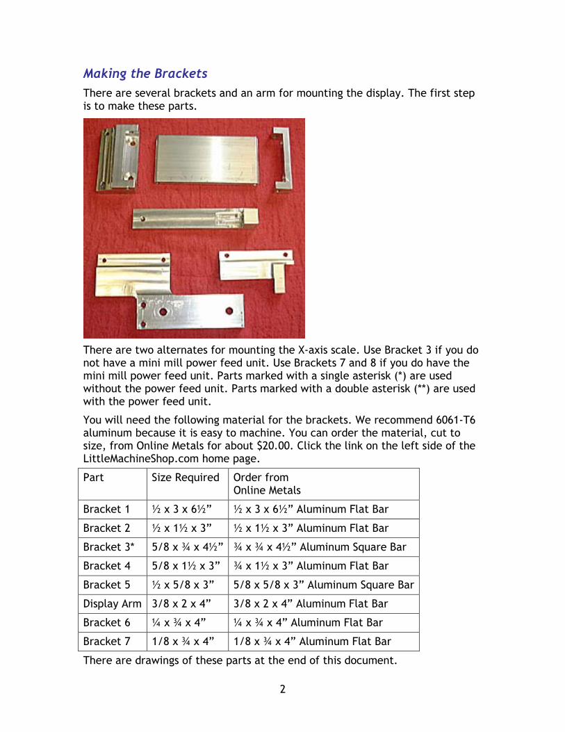
Making the Brackets There are several brackets and an arm for mounting the display. The first step is to make these parts.
There are two alternates for mounting the X-axis scale. Use Bracket 3 if you do not have a mini mill power feed unit. Use Brackets 7 and 8 if you do have the mini mill power feed unit. Parts marked with a single asterisk (*) are used without the power feed unit. Parts marked with a double asterisk (**) are used with the power feed unit.
You will need the following material for the brackets. We recommend 6061-T6 aluminum because it is easy to machine. You can order the material, cut to size, from Online Metals for about $20.00. Click the link on the left side of the LittleMachineShop.com home page.
Part Size Required Order from Online Metals
Bracket 1 ½ x 3 x 6½” ½ x 3 x 6½” Aluminum Flat Bar
Bracket 2 ½ x 1½ x 3” ½ x 1½ x 3” Aluminum Flat Bar
Bracket 3* 5/8 x ¾ x 4½” ¾ x ¾ x 4½” Aluminum Square Bar
Bracket 4 5/8 x 1½ x 3” ¾ x 1½ x 3” Aluminum Flat Bar
Bracket 5 ½ x 5/8 x 3” 5/8 x 5/8 x 3” Aluminum Square Bar
Display Arm 3/8 x 2 x 4” 3/8 x 2 x 4” Aluminum Flat Bar
Bracket 6 ¼ x ¾ x 4” ¼ x ¾ x 4” Aluminum Flat Bar
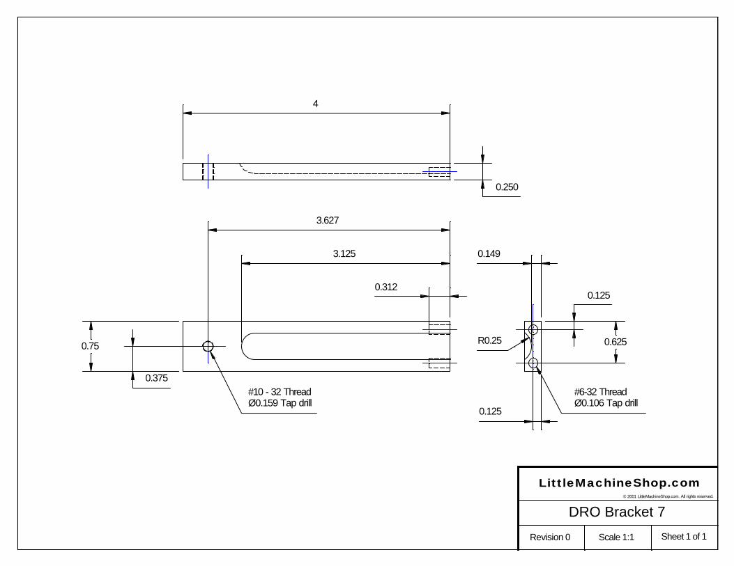
Bracket 7 1/8 x ¾ x 4” 1/8 x ¾ x 4” Aluminum Flat Bar
There are drawings of these parts at the end of this document.
3
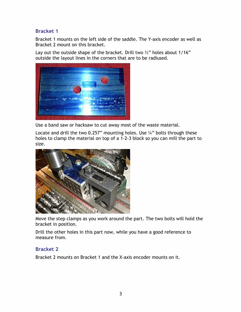
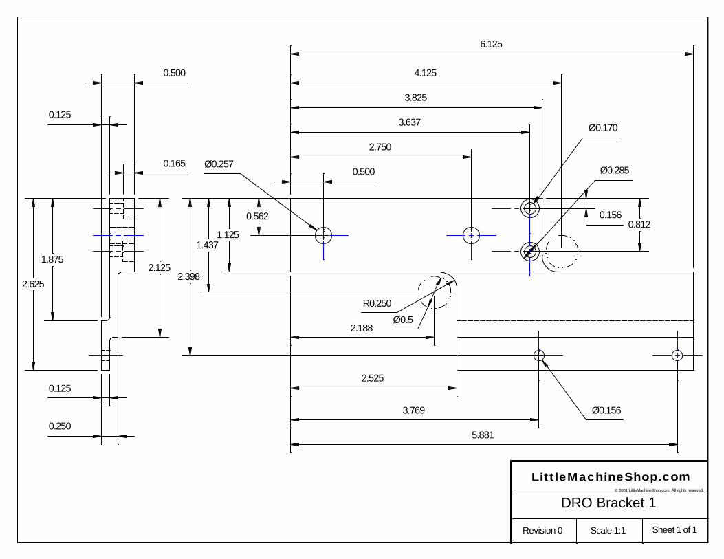
Bracket 1 Bracket 1 mounts on the left side of the saddle. The Y-axis encoder as well as Bracket 2 mount on this bracket.
Lay out the outside shape of the bracket. Drill two ½” holes about 1/16” outside the layout lines in the corners that are to be radiused.
Use a band saw or hacksaw to cut away most of the waste material.
Locate and drill the two 0.257” mounting holes. Use ¼” bolts through these holes to clamp the material on top of a 1-2-3 block so you can mill the part to size.
Move the step clamps as you work around the part. The two bolts will hold the bracket in position.
Drill the other holes in this part now, while you have a good reference to measure from.
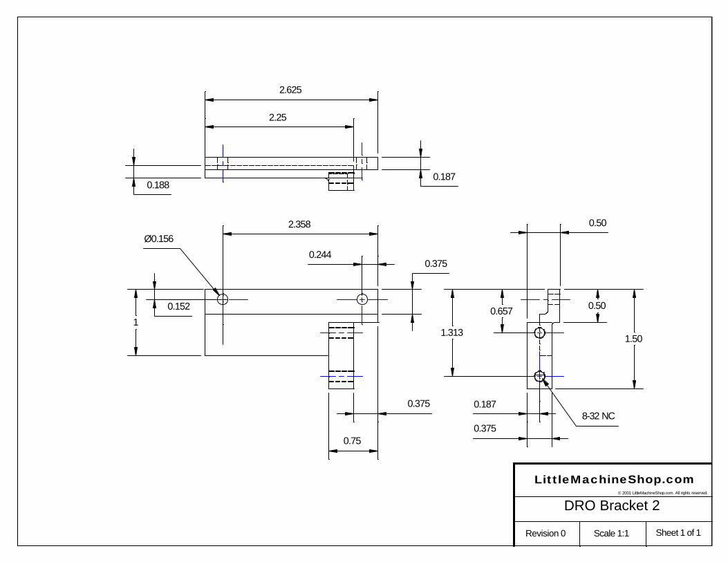
Bracket 2 Bracket 2 mounts on Bracket 1 and the X-axis encoder mounts on it.
4
Bracket 3* Bracket 3 extends the mill table to the left and mounts the end of the X-axis rack. Make this bracket if you do not have a mini mill power feed unit. If you have the mini mill power feed unit, make brackets 7 and 8 instead.
Bracket 4 Bracket 4 mounts the Z-axis encoder and the arm for the display.
Bracket 5 Bracket 5 mounts the display to the display arm.
Display Arm The Display arm goes between Bracket 4 and Bracket 5.
Brackets 7 and 8** These brackets extend the mill table to the left and mount the end of the X-axis rack. Make these brackets if you have a mini mill power feed unit. If you do not have the mini mill power feed unit, make bracket 3 instead.
Mounting the DRO Once the brackets are completed, the next step is to mount them on the mini mill.
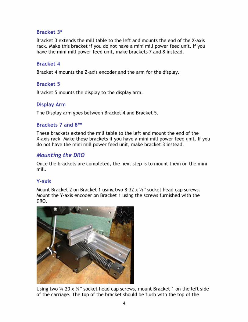
Y-axis Mount Bracket 2 on Bracket 1 using two 8-32 x ½” socket head cap screws. Mount the Y-axis encoder on Bracket 1 using the screws furnished with the DRO.
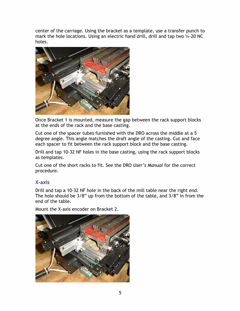
Using two ¼-20 x ¾” socket head cap screws, mount Bracket 1 on the left side of the carriage. The top of the bracket should be flush with the top of the
5
center of the carriage. Using the bracket as a template, use a transfer punch to mark the hole locations. Using an electric hand drill, drill and tap two ¼-20 NC holes.
Once Bracket 1 is mounted, measure the gap between the rack support blocks at the ends of the rack and the base casting.
Cut one of the spacer tubes furnished with the DRO across the middle at a 5 degree angle. This angle matches the draft angle of the casting. Cut and face each spacer to fit between the rack support block and the base casting.
Drill and tap 10-32 NF holes in the base casting, using the rack support blocks as templates.
Cut one of the short racks to fit. See the DRO User’s Manual for the correct procedure.
X-axis Drill and tap a 10-32 NF hole in the back of the mill table near the right end. The hole should be 3/8” up from the bottom of the table, and 3/8” in from the end of the table.
Mount the X-axis encoder on Bracket 2.
6
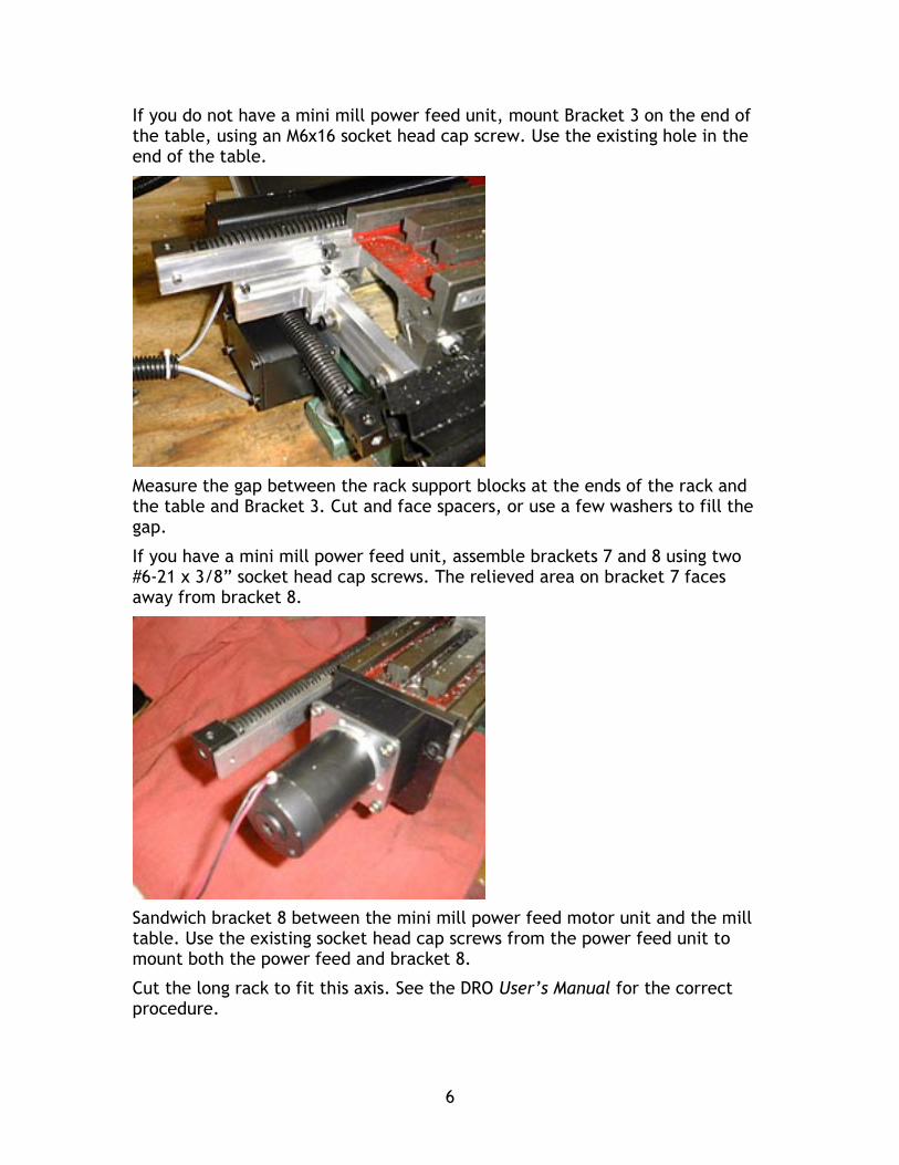
If you do not have a mini mill power feed unit, mount Bracket 3 on the end of the table, using an M6x16 socket head cap screw. Use the existing hole in the end of the table.
Measure the gap between the rack support blocks at the ends of the rack and the table and Bracket 3. Cut and face spacers, or use a few washers to fill the gap.
If you have a mini mill power feed unit, assemble brackets 7 and 8 using two #6-21 x 3/8” socket head cap screws. The relieved area on bracket 7 faces away from bracket 8.
Sandwich bracket 8 between the mini mill power feed motor unit and the mill table. Use the existing socket head cap screws from the power feed unit to mount both the power feed and bracket 8.
Cut the long rack to fit this axis. See the DRO User’s Manual for the correct procedure.
7
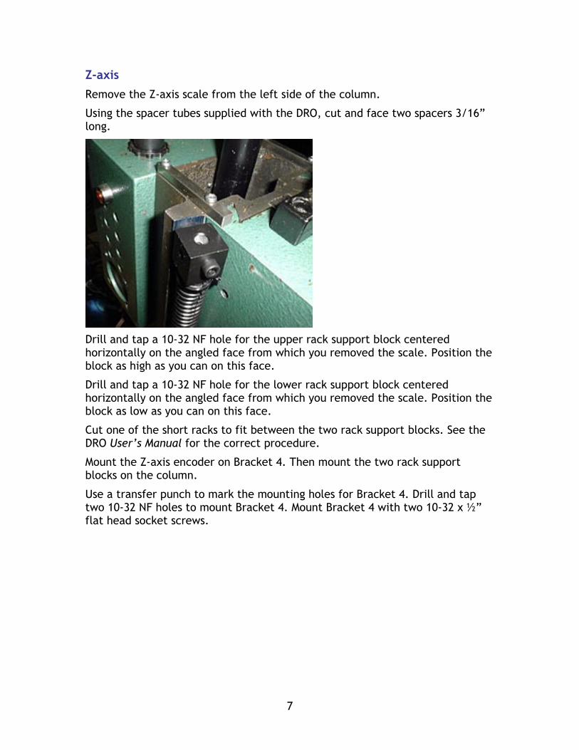
Z-axis Remove the Z-axis scale from the left side of the column.
Using the spacer tubes supplied with the DRO, cut and face two spacers 3/16” long.
Drill and tap a 10-32 NF hole for the upper rack support block centered horizontally on the angled face from which you removed the scale. Position the block as high as you can on this face.
Drill and tap a 10-32 NF hole for the lower rack support block centered horizontally on the angled face from which you removed the scale. Position the block as low as you can on this face.
Cut one of the short racks to fit between the two rack support blocks. See the DRO User’s Manual for the correct procedure.
Mount the Z-axis encoder on Bracket 4. Then mount the two rack support blocks on the column.
Use a transfer punch to mark the mounting holes for Bracket 4. Drill and tap two 10-32 NF holes to mount Bracket 4. Mount Bracket 4 with two 10-32 x ½” flat head socket screws.
8
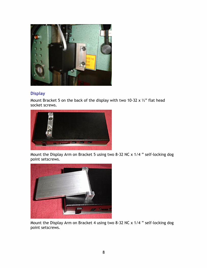
Display Mount Bracket 5 on the back of the display with two 10-32 x ½” flat head socket screws.
Mount the Display Arm on Bracket 5 using two 8-32 NC x 1/4 ” self-locking dog point setscrews.
Mount the Display Arm on Bracket 4 using two 8-32 NC x 1/4 ” self-locking dog point setscrews.
9
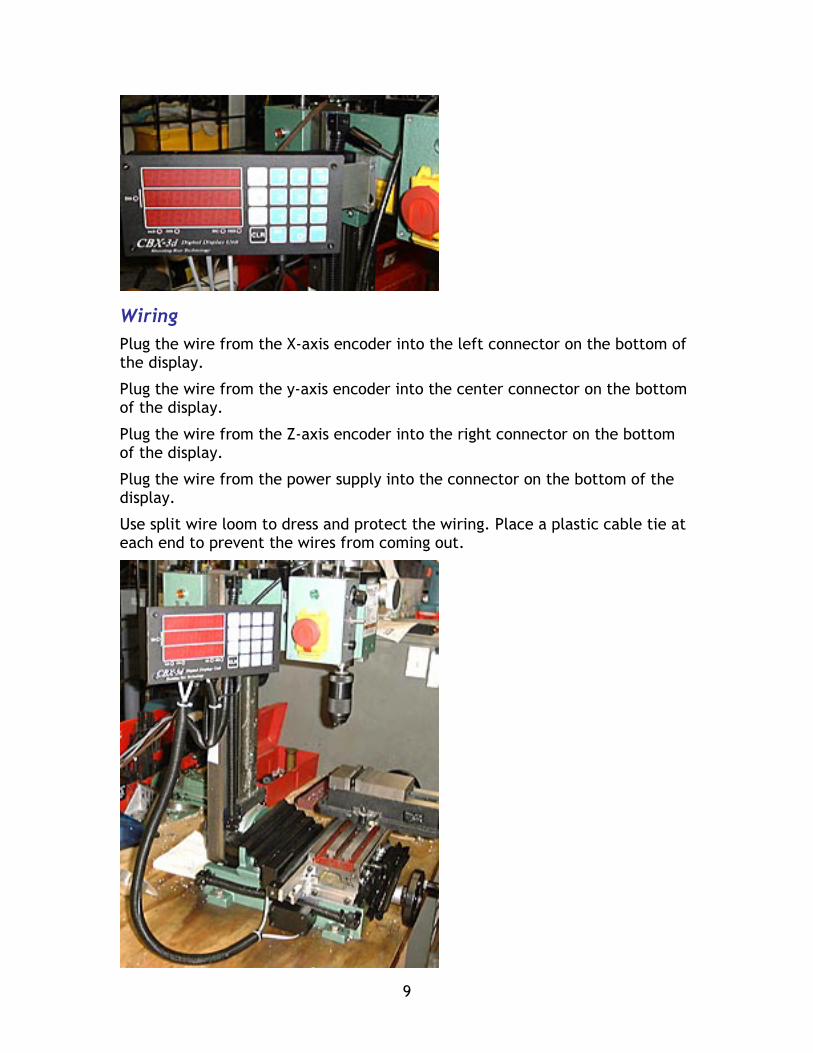
Wiring Plug the wire from the X-axis encoder into the left connector on the bottom of the display.
Plug the wire from the y-axis encoder into the center connector on the bottom of the display.
Plug the wire from the Z-axis encoder into the right connector on the bottom of the display.
Plug the wire from the power supply into the connector on the bottom of the display.
Use split wire loom to dress and protect the wiring. Place a plastic cable tie at each end to prevent the wires from coming out.
10
2.625
3.825
6.125
2.525
0.562
0.500
2.750
3.637
3.769
5.881
2.398
0.1560.812
0.125
1.125
Ø0.257
Ø0.170
Ø0.156
0.165
0.250
1.8752.125
Ø0.285
0.500
0.125
R0.250
2.188
1.437
4.125
Ø0.5
LittleMachineShop.com
Sheet 1 of 1Scale 1:1Revision 0
DRO Bracket 1© 2001 LittleMachineShop.com. All rights reserved.
2.25
1
2.358
8-32 NC
Ø0.156
0.152 0.657
1.313
0.1880.187
0.375
0.50
0.3750.244
0.375
0.75
2.625
0.50
1.50
0.187
LittleMachineShop.com
Sheet 1 of 1Scale 1:1Revision 0
DRO Bracket 2© 2001 LittleMachineShop.com. All rights reserved.
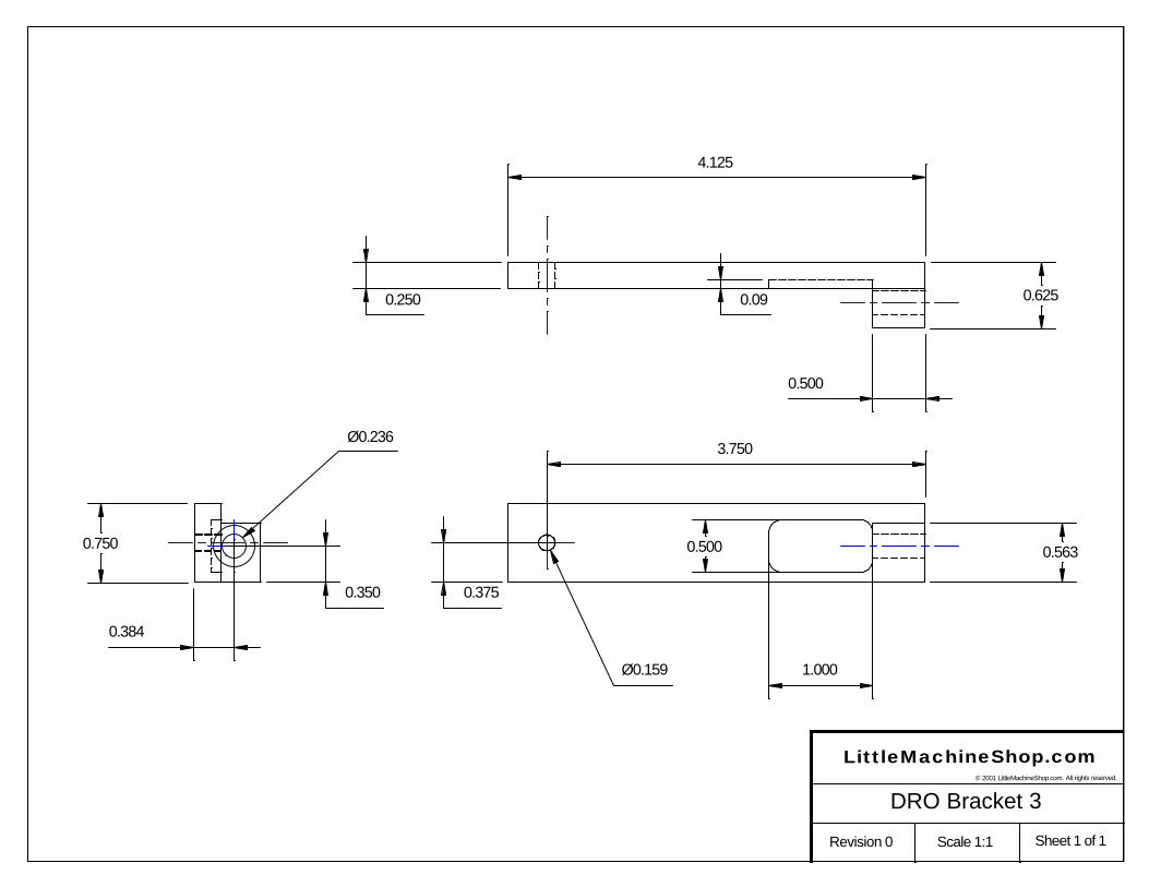
4.125
0.625
0.750
0.250
0.500
1.000
0.500 0.563
0.384
0.350 0.375
3.750
Ø0.159
Ø0.236
0.09
LittleMachineShop.com
Sheet 1 of 1Scale 1:1Revision 0
DRO Bracket 3© 2001 LittleMachineShop.com. All rights reserved.
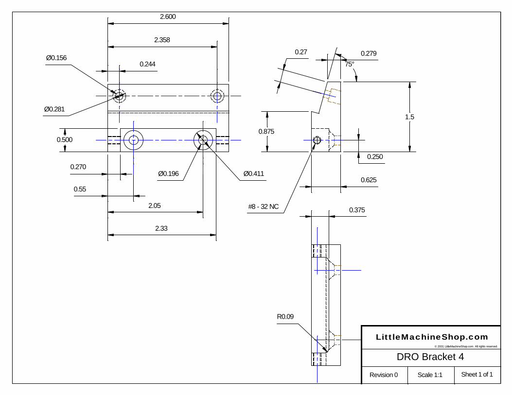
2.600
0.500
0.250
0.625
0.270
0.55
2.05
2.33
Ø0.156
Ø0.196 Ø0.411
#8 - 32 NC
Ø0.281
0.375
R0.09
0.279
75°
0.875
1.5
0.27
0.244
2.358
LittleMachineShop.com
Sheet 1 of 1Scale 1:1Revision 0
DRO Bracket 4© 2001 LittleMachineShop.com. All rights reserved.
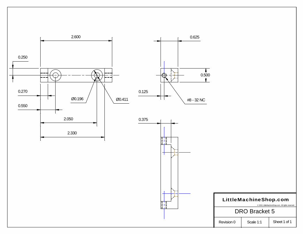
0.270
0.550
2.050
2.330
2.600 0.625
0.250
0.125
0.500
0.375
Ø0.196 Ø0.411 #8 - 32 NC
LittleMachineShop.com
Sheet 1 of 1Scale 1:1Revision 0
DRO Bracket 5© 2001 LittleMachineShop.com. All rights reserved.
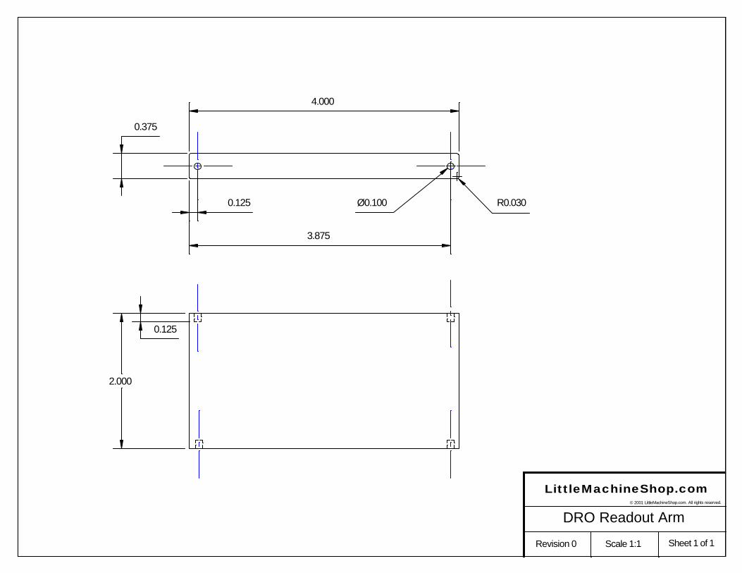
0.375
2.000
0.125
4.000
0.125
3.875
Ø0.100 R0.030
LittleMachineShop.com
Sheet 1 of 1Scale 1:1Revision 0
DRO Readout Arm© 2001 LittleMachineShop.com. All rights reserved.
4
0.375
3.627
#10 - 32 ThreadØ0.159 Tap drill
0.75
0.250
0.125
0.625
#6-32 ThreadØ0.106 Tap drill
0.312
R0.25
0.149
0.125
3.125
LittleMachineShop.com
Sheet 1 of 1Scale 1:1Revision 0
DRO Bracket 7© 2001 LittleMachineShop.com. All rights reserved.
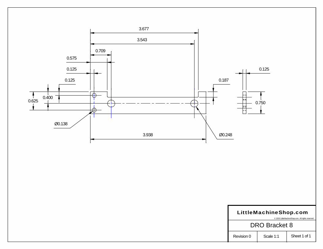
0.750
0.125
0.575
0.709
3.543
3.677
3.938
0.187
0.6250.400
0.125
0.125
Ø0.248
Ø0.138
LittleMachineShop.com
Sheet 1 of 1Scale 1:1Revision 0
DRO Bracket 8© 2003 LittleMachineShop.com. All rights reserved.