Embed Size (px)
Citation preview
Ship’s Wheel Tutorial
Allan Yedlinksy
Building the ship’s wheel can be done in several ways. As with the tutorial on the building of the capstan, a milling set up and drill press help, but is absolutely not necessary. They save time but an equally good quality wheel can be made with hand tools. There are several parts to be made for the wheel, plus the drum and stanchions. The wheel rim should be made in 10 or 12 segments depending on if it will have 10 or 12 spokes. MOST real ships never had 8 spoked wheels so if some realism is important to you, figure 10 or 12 spokes. A notable exception is the USS Constitution's double wheel, which is in Wiley Hall on the grounds of the US Merchant Marine Academy in Kings Point, New York. Another point to which attention should be paid is scale. Personally I have never seen a store bought wheel that is properly scaled. They may be out there, but I would imagine the price would be prohibitive. The spoke handles on these prefabricated units are often around 6” diameter, not the proper 2” or so dimension one needs to get his hand around it. The rim us only about 2-3” thick and about 3-4 inches wide in most cases. These make for delicate parts in ¼ scale, and darned fragile in smaller scales. This brings me to another point, wood. PLEASE do not use any wood that is not hard and close grained. It will not hold up to semi rough handling and proper finishing. I base this on experience, not opinion. The wheel diameter overall is about 5’- 2” including the spokes. Again, this varied a little so if yours turns out to be 5’ 1” or 5’4” no problem, just be sure to adjust the stanchion height accordingly so the spokes do not hit the deck. For the wheel itself for Triton or Boreas or other ships with a ten spoke wheel, there will be 10 rim segments, ten spokes, one hub and two rim rings unless one chooses to make these rim rings as part of the initial rim segments. The basic wheel designs were consistent for many years from ship to ship, but the actual construction varied from yard to yard. To start construction I drew a circle of the appropriate diameter for the hub, rim ID and OD, and outside of the spoke handles. I then drew in 10 lines from the center, 36º apart. From this drawing you can measure the MAXIMUM length of any one of the rim segments. Next cut a strip of wood that is 2 or 3 times the final width of the rim. Set up a cutting jig or if using a small table saw, set it up to cut 10 pieces with 18 degree angles on each end of the segment making sure the length is that long dimension measured on the drawing. If it is a hair long, use a good sharp chisel and shave off enough such that every segment is exactly the same length. If they are a couple thousandths too long or too short, but identical from piece to piece, you will have a good rim, albeit a diameter that may be a hair over or under what you were shooting for. This is not a bad thing, but if the lengths or angles are different from segment to segment, you will not get a good fit all the way around.
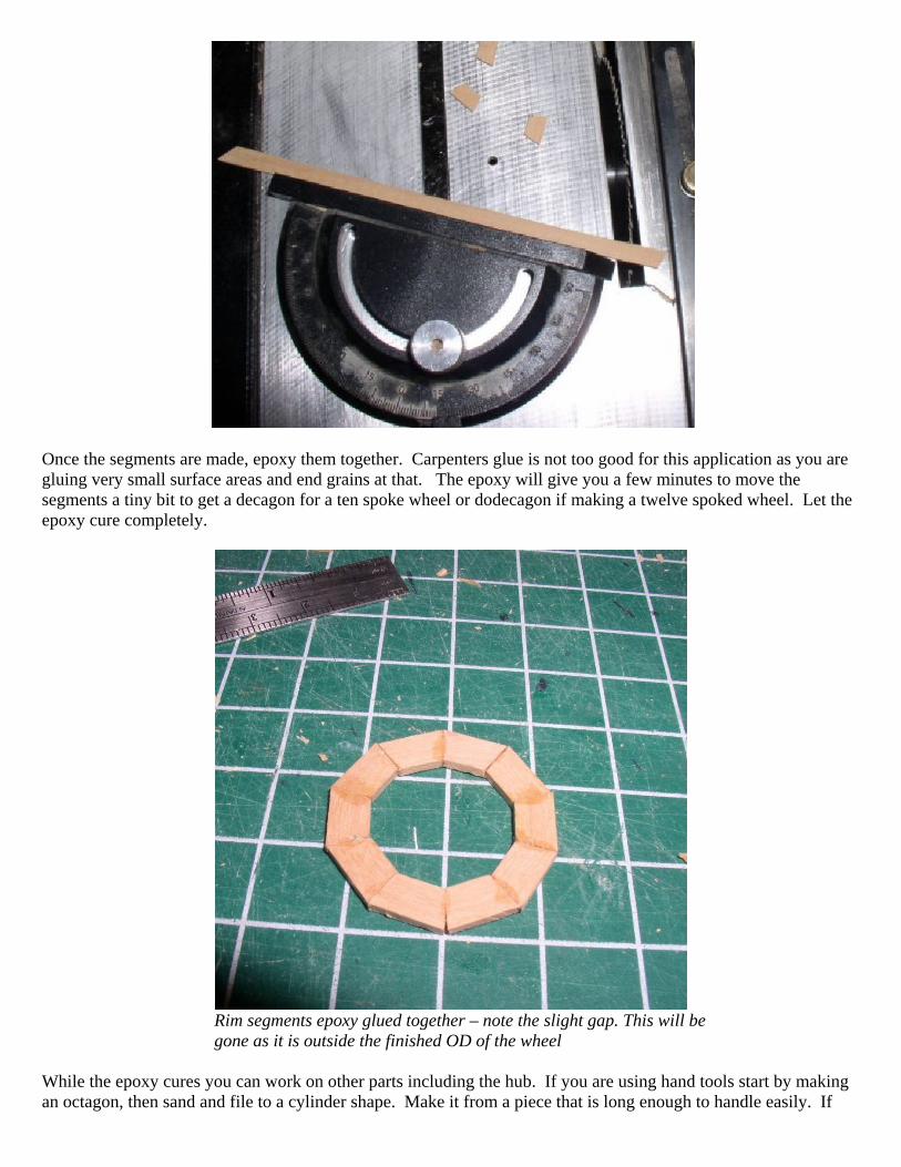
Once the segments are made, epoxy them together. Carpenters glue is not too good for this application as you are gluing very small surface areas and end grains at that. The epoxy will give you a few minutes to move the segments a tiny bit to get a decagon for a ten spoke wheel or dodecagon if making a twelve spoked wheel. Let the epoxy cure completely.
Rim segments epoxy glued together – note the slight gap. This will be gone as it is outside the finished OD of the wheel
While the epoxy cures you can work on other parts including the hub. If you are using hand tools start by making an octagon, then sand and file to a cylinder shape. Make it from a piece that is long enough to handle easily. If
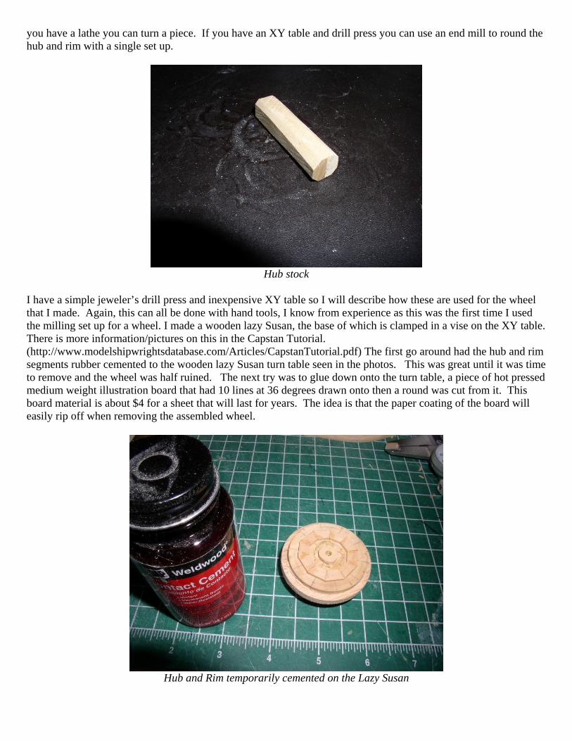
you have a lathe you can turn a piece. If you have an XY table and drill press you can use an end mill to round the hub and rim with a single set up.
Hub stock
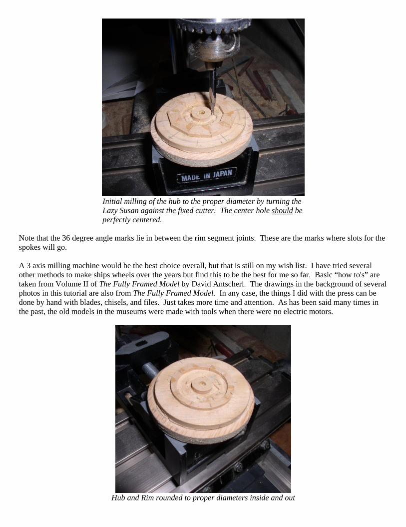
I have a simple jeweler’s drill press and inexpensive XY table so I will describe how these are used for the wheel that I made. Again, this can all be done with hand tools, I know from experience as this was the first time I used the milling set up for a wheel. I made a wooden lazy Susan, the base of which is clamped in a vise on the XY table. There is more information/pictures on this in the Capstan Tutorial. (http://www.modelshipwrightsdatabase.com/Articles/CapstanTutorial.pdf) The first go around had the hub and rim segments rubber cemented to the wooden lazy Susan turn table seen in the photos. This was great until it was time to remove and the wheel was half ruined. The next try was to glue down onto the turn table, a piece of hot pressed medium weight illustration board that had 10 lines at 36 degrees drawn onto then a round was cut from it. This board material is about $4 for a sheet that will last for years. The idea is that the paper coating of the board will easily rip off when removing the assembled wheel.
Hub and Rim temporarily cemented on the Lazy Susan
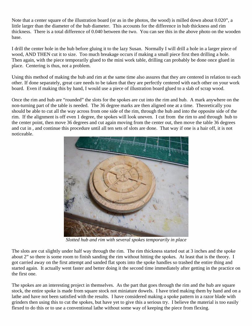
Initial milling of the hub to the proper diameter by turning the Lazy Susan against the fixed cutter. The center hole should be perfectly centered.
Note that the 36 degree angle marks lie in between the rim segment joints. These are the marks where slots for the spokes will go. A 3 axis milling machine would be the best choice overall, but that is still on my wish list. I have tried several other methods to make ships wheels over the years but find this to be the best for me so far. Basic “how to's” are taken from Volume II of The Fully Framed Model by David Antscherl. The drawings in the background of several photos in this tutorial are also from The Fully Framed Model. In any case, the things I did with the press can be done by hand with blades, chisels, and files. Just takes more time and attention. As has been said many times in the past, the old models in the museums were made with tools when there were no electric motors.
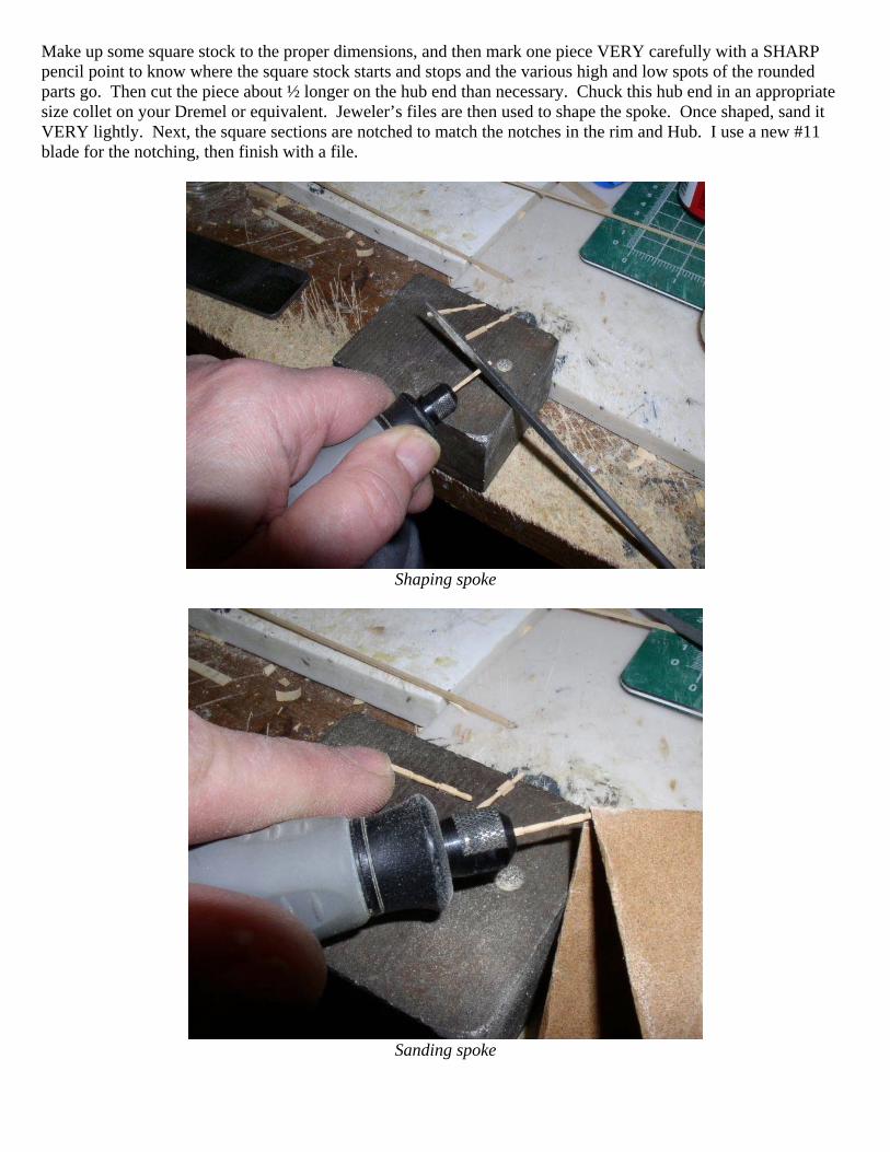
Hub and Rim rounded to proper diameters inside and out
Note that a center square of the illustration board (or as in the photos, the wood) is milled down about 0.020”, a little larger than the diameter of the hub diameter. This accounts for the difference in hub thickness and rim thickness. There is a total difference of 0.040 between the two. You can see this in the above photo on the wooden base. I drill the center hole in the hub before gluing it to the lazy Susan. Normally I will drill a hole in a larger piece of wood, AND THEN cut it to size. Too much breakage occurs if making a small piece first then drilling a hole. Then again, with the piece temporarily glued to the mini work table, drilling can probably be done once glued in place. Centering is thus, not a problem. Using this method of making the hub and rim at the same time also assures that they are centered in relation to each other. If done separately, great care needs to be taken that they are perfectly centered with each other on your work board. Even if making this by hand, I would use a piece of illustration board glued to a slab of scrap wood. Once the rim and hub are “rounded” the slots for the spokes are cut into the rim and hub. A mark anywhere on the non-turning part of the table is needed. The 36 degree marks are then aligned one at a time. Theoretically you should be able to cut all the way across from one side of the rim, through the hub and into the opposite side of the rim. If the alignment is off even 1 degree, the spokes will look uneven. I cut from the rim to and through hub to the center point, then move 36 degrees and cut again moving from the center out, then move the table 36 degrees and cut in , and continue this procedure until all ten sets of slots are done. That way if one is a hair off, it is not noticeable.
Slotted hub and rim with several spokes temporarily in place
The slots are cut slightly under half way through the rim. The rim thickness started out at 3 inches and the spoke about 2” so there is some room to finish sanding the rim without hitting the spokes. At least that is the theory. I got carried away on the first attempt and sanded flat spots into the spoke handles so trashed the entire thing and started again. It actually went faster and better doing it the second time immediately after getting in the practice on the first one. The spokes are an interesting project in themselves. As the part that goes through the rim and the hub are square stock, the entire spoke is made from square stock not miniature dowels. I have tried making them by hand and on a lathe and have not been satisfied with the results. I have considered making a spoke pattern in a razor blade with grinders then using this to cut the spokes, but have yet to give this a serious try. I believe the material is too easily flexed to do this or to use a conventional lathe without some way of keeping the piece from flexing.
Make up some square stock to the proper dimensions, and then mark one piece VERY carefully with a SHARP pencil point to know where the square stock starts and stops and the various high and low spots of the rounded parts go. Then cut the piece about ½ longer on the hub end than necessary. Chuck this hub end in an appropriate size collet on your Dremel or equivalent. Jeweler’s files are then used to shape the spoke. Once shaped, sand it VERY lightly. Next, the square sections are notched to match the notches in the rim and Hub. I use a new #11 blade for the notching, then finish with a file.
Shaping spoke
Sanding spoke
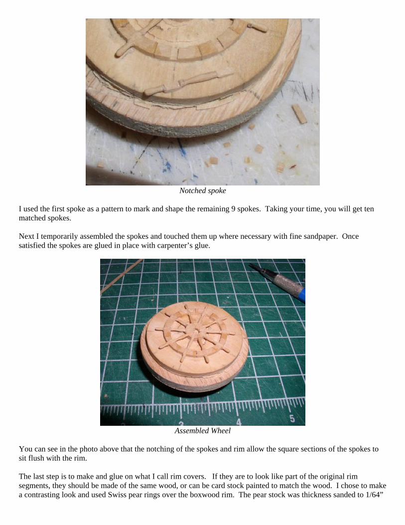
Notched spoke
I used the first spoke as a pattern to mark and shape the remaining 9 spokes. Taking your time, you will get ten matched spokes. Next I temporarily assembled the spokes and touched them up where necessary with fine sandpaper. Once satisfied the spokes are glued in place with carpenter’s glue.
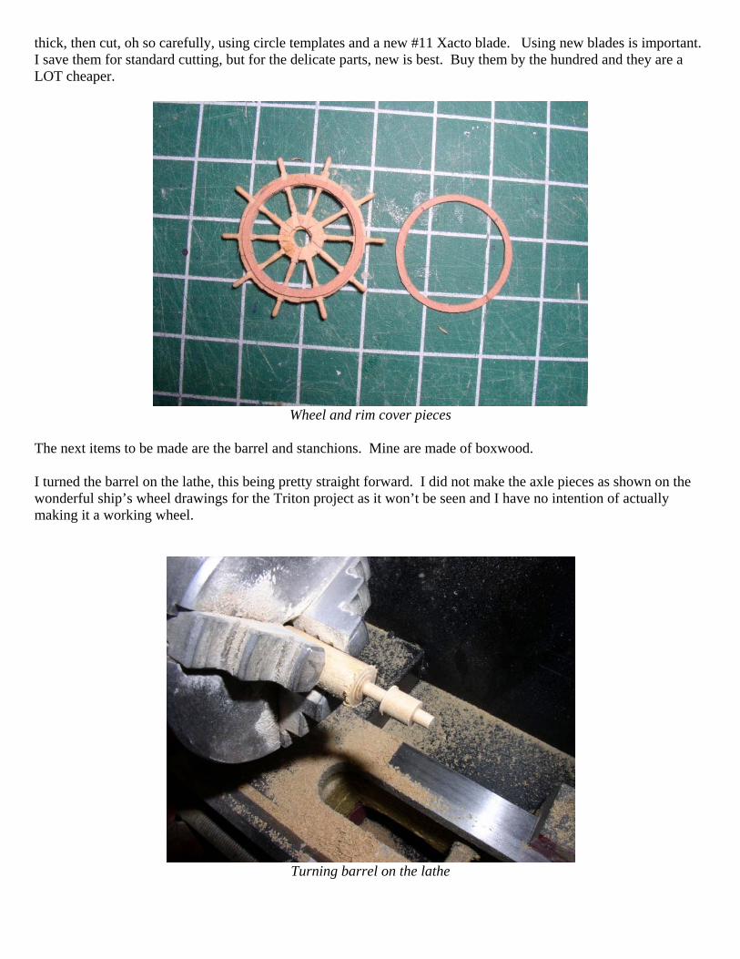
Assembled Wheel
You can see in the photo above that the notching of the spokes and rim allow the square sections of the spokes to sit flush with the rim. The last step is to make and glue on what I call rim covers. If they are to look like part of the original rim segments, they should be made of the same wood, or can be card stock painted to match the wood. I chose to make a contrasting look and used Swiss pear rings over the boxwood rim. The pear stock was thickness sanded to 1/64”
thick, then cut, oh so carefully, using circle templates and a new #11 Xacto blade. Using new blades is important. I save them for standard cutting, but for the delicate parts, new is best. Buy them by the hundred and they are a LOT cheaper.
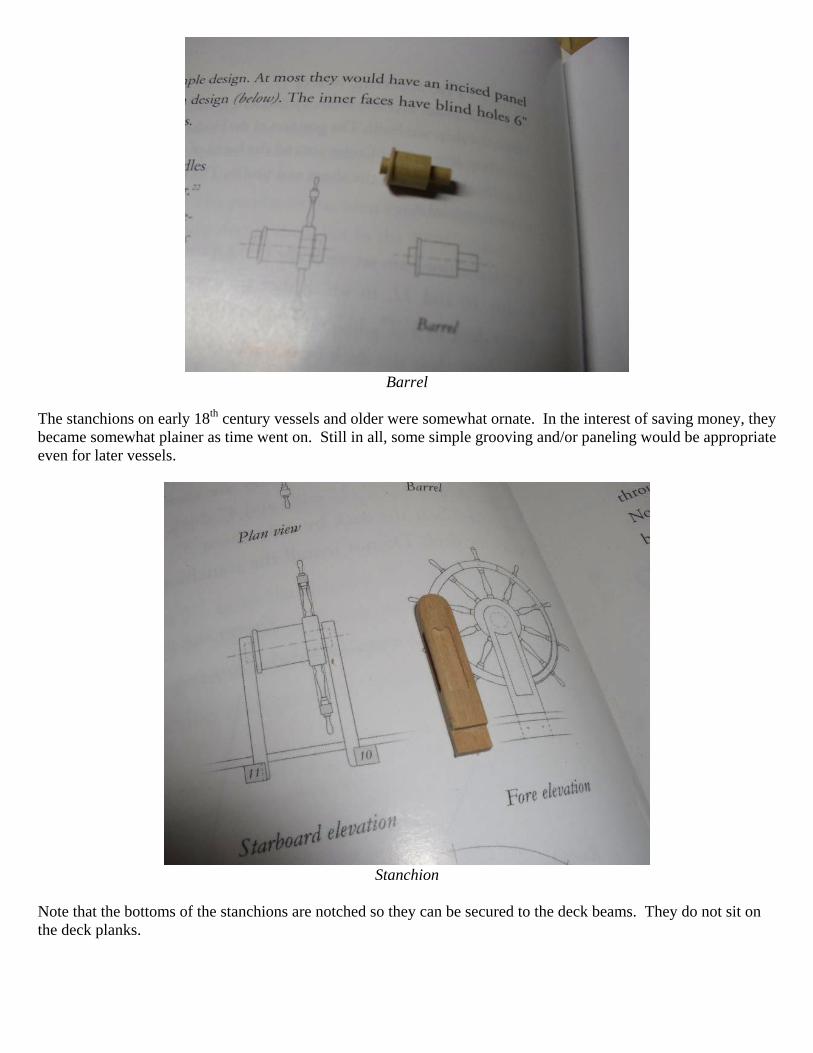
Wheel and rim cover pieces
The next items to be made are the barrel and stanchions. Mine are made of boxwood. I turned the barrel on the lathe, this being pretty straight forward. I did not make the axle pieces as shown on the wonderful ship’s wheel drawings for the Triton project as it won’t be seen and I have no intention of actually making it a working wheel.
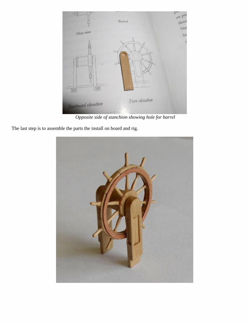
Turning barrel on the lathe
Barrel
The stanchions on early 18th century vessels and older were somewhat ornate. In the interest of saving money, they became somewhat plainer as time went on. Still in all, some simple grooving and/or paneling would be appropriate even for later vessels.
Stanchion
Note that the bottoms of the stanchions are notched so they can be secured to the deck beams. They do not sit on the deck planks.
Opposite side of stanchion showing hole for barrel
The last step is to assemble the parts the install on board and rig.