Embed Size (px)
Citation preview

Shipcontroller
SCR750 series Remote Unit
User Guide Firmware 5.1
SCR750-UG-EN-V51

2
______________________________________________________________
Shipcontroller – SC750-UG-EN-V51
Manufacturer:
Naocontrol, S.L. Félix Acevedo, 1, 6D2 15008 A Coruña
SPAIN
Website: www.naocontrol.com
Email: [email protected]
This equipment meets the requirements of the EU (European Union) concerning
safety and electromagnetic compatibility regulations. Please refer to the
Shipcontroller series 700 system reference manual to read the CE certificate for
the whole Shipcontroller SC700 system.
© 2018 Naocontrol, S.L.
All Rights Reserved

3
______________________________________________________________
Shipcontroller – SC750-UG-EN-V51
Table of contents
1 Preface.......................................................................
2 Safety and environmental warnings ........................
3 Device description ....................................................
3.1 Warning LEDs
3.2 Power button
3.3 Starboard engine ahead-fast button
3.4 Starboard engine slow toggle control lever
3.5 Starboard engine astern-fast control button
3.6 Stern thruster toggle control lever
3.7 Menu + / Auxiliary channel 1 pushbutton
3.8 Internal Vibrator
3.9 Menu Button/Change Screen Button
3.10 Charging indicator
3.11 Menu (-) / Auxiliary channel 2 pushbutton
3.12 Port engine astern-fast control button
3.13 Port engine slow toggle control lever
3.14 Port engine ahead-fast control button
3.15 Display
3.16 Windlass pushbuttons
3.17 Bow thruster toggle control lever
6
7
9
11
12
13
14
15

4
______________________________________________________________
Shipcontroller – SC750-UG-EN-V51
4 Device Operation .......................................................
4.1 Basic operation and functions
4.1.1 Turning the unit on
4.1.2 Turning the unit off
4.1.3 Checking the radio coverage
4.2 Navigating through screens and menus
4.2.1 NAV DATA/DOCKING screen
4.2.2 ENGINE CTRL screen
4.2.3 CHAIN CNTR screen
4.2.4 WINDLASS screen
4.2.5 AUTOPILOT screen
4.2.6 AP MENU screen
4.2.7 WIND screen
4.2.8 ENGINES screen
4.2.9 AUTOMATION screen
4.2.10 EDIT LABEL screen
4.2.11 RF MNTR screen
4.2.12 SETTINGS screen
4.3 Settings
4.3.1 Chain counter calibration
4.3.2 Depth alarm mode
4.3.3 Depth alarm level
4.3.4 Thrusters Inhibition
4.3.5 Autopilot screen enabling
4.3.6 Various screens enabling
4.3.7 Auto screen change
4.3.8 End settings
16
16
17
19
20
21
22
23
24
25
26
27
28

5
______________________________________________________________
Shipcontroller – SC750-UG-EN-V51
4.4 Engine control
4.4.1 Taking engine control
4.4.2 Engine control signaling
4.4.3 Engine control priorities
4.5 Secondary systems control
4.5.1 Thrusters control
4.5.2 Windlass control
4.5.3 Auxiliary control channels
4.6 Battery Charging
5 Technical Information ...............................................
6 Troubleshooting ........................................................
7 Warranty Information ................................................
29
30
32
33
34
35
36
37

6
______________________________________________________________
Shipcontroller – SC750-UG-EN-V51
1 Preface The remote control unit SCR750 series, update 5.1 brings the following
capabilities or features:
Support of up to eight active antennas deployed across the boat. (NET
version).
Support of multiple remote units sharing the same radio network.
(NET version).
It includes a sunlight readable hybrid e-ink display allowing to view
the telemetry data.
It allows to process and show telemetry data, such as:
o Boat speed, course and depth.
o Wind speed and direction.
o Chain count.
o Engines rpm.
o Two analog voltage channels.
o Engine control status.
Stepped proportional control for two engines (Slow/Fast controls).
Control levers for two thrusters.
Control buttons for two windlasses.
Control of an optional Automation module, allowing to control up to 8
digital relay outputs.
Buttons for direct control of two auxiliary control channels (Horn,
light).
Option for controlling a compatible autopilot.
Menu commands to reset chain counter and claim control head control.
Depth Alarm: raises an alarm if the depth is less than the configured
value.
Thruster inhibition: disables the thrusters if the boat's speed is greater
than the speed limit set.
Rechargeable internal Lithium-Polymer battery.
IP67K micro-USB battery charging input or wireless charger.
IP65 watertight.
7
______________________________________________________________
Shipcontroller – SC750-UG-EN-V51
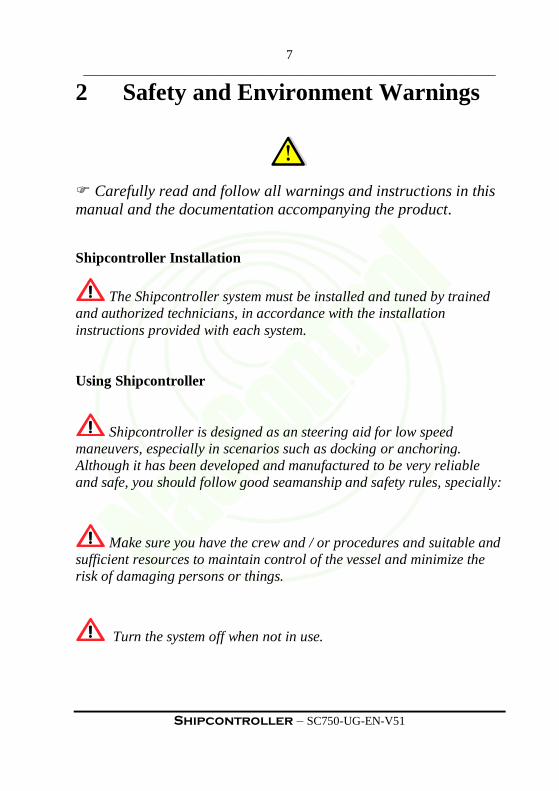
2 Safety and Environment Warnings
Carefully read and follow all warnings and instructions in this
manual and the documentation accompanying the product.
Shipcontroller Installation
The Shipcontroller system must be installed and tuned by trained
and authorized technicians, in accordance with the installation
instructions provided with each system.
Using Shipcontroller
Shipcontroller is designed as an steering aid for low speed
maneuvers, especially in scenarios such as docking or anchoring.
Although it has been developed and manufactured to be very reliable
and safe, you should follow good seamanship and safety rules, specially:
Make sure you have the crew and / or procedures and suitable and
sufficient resources to maintain control of the vessel and minimize the
risk of damaging persons or things.
Turn the system off when not in use.

8
______________________________________________________________
Shipcontroller – SC750-UG-EN-V51
ENVIRONMENTAL WARNINGS
Restriction of Hazardous Substances (RoHS)
RoHS
Using disposable or rechargeable batteries:
Product Disposal:
When you decide to discard this product, for example,
at the end of its life cycle, do it according to the
ordinances or regulations governing the disposal of
electronics devices.
The remote control unit is designed to use rechargeable
batteries. Batteries must be disposed according to
current regulations, placing them in a suitable
container.
This system has been designed in accordance with
RoHS regulations, which restricts the use of substances
harmful to the environment, such as lead, mercury or
cadmium.

9
______________________________________________________________
Shipcontroller – SC750-UG-EN-V51
3 Device description
Figure 1
2. Power button
3. Starboard
engine: ahead-fast
button
4. Starboard
engine: slow
ahead/astern lever
5. Starboard
engine: astern-fast
button
6. Stern thruster
lever
9. Menu / change
screen button
7. Auxiliary channel
1 / Menu (+) / Yes
button
15. Display
11. Auxiliary
channel 2 / Menu
(-) / No button
12. Port engine:
astern-fast button
13. Port engine:
ahead slow/
astern slow
switch
14. Port engine
ahead-fast button
16. Windlass
buttons
17. Bow
thruster switch 1. Status lights
8. Internal Vibrator
10. Charging
indicator

10
______________________________________________________________
Shipcontroller – SC750-UG-EN-V51
The SCR755 remote control unit has the following types of controls or
indicators:
Indicators:
Status led lights: green and red LEDs (1)
Display (15)
Internal vibrator (8)
Battery charging indicator (10)
Engine controls:
Starboard slow ahead/astern toggle control lever (4)
Starboard ahead-fast pushbutton (3)
Starboard astern-fast pushbutton (5)
Port slow ahead/astern toggle control lever (13)
Port ahead-fast pushbutton (14)
Port astern-fast pushbutton (12)
Windlass and Thrusters controls:
Bow thruster toggle control lever (17)
Stern thruster toggle control lever (6)
Windlass up/windlass down pushbuttons (16)
Other controls:
Power on/off pushbutton (2)
Menu / Change screen pushbutton (9)
Auxiliary 1 (Horn) / Menu (+)/YES pushbutton (7)
Auxiliary 2 (Light) / Menu (-)/NO pushbutton (11)

11
______________________________________________________________
Shipcontroller – SC750-UG-EN-V51
3.1 Warning LEDs
The warning LEDs provide system status information.
Green light Red light Meaning
ON OFF Wireless data link established and operative. Base
system operative. Engine controls ready.
SLOW
BLINKING
(1/sec)
OFF Wireless data link established and operative. Base
system operative. Engine controls not ready.
FAST
BLINKING
OFF Some control button has been activated, and the
remote is trying to send user commands to the
base transceiver.
OFF ON No radio coverage or base system is powered off.
SLOW
BLINKING
Battery low.
SLOW
BLINKING
SLOW
BLINKING
Remote unit failure.
Table 1
3.2 Power button
This button allows you to turn the remote control unit on and off, and
displaying the boat name and other system parameters.
3.3 Starboard engine ahead-fast button
If the system includes the multi- speed option, this button activates the
starboard ahead-fast command for the starboard engine. The term "fast" is
relative and does not mean high rpm or high speed. If multi-speed option is not
available this button activates the ahead-slow command.

12
______________________________________________________________
Shipcontroller – SC750-UG-EN-V51
3.4 Starboard engine slow toggle control lever
This is a toggle lever: push it forward to activate the ahead-slow command, or
push it backward to activate astern-slow. The lever returns to neutral (central)
position by itself.
3.5 Starboard engine astern-fast control button
If your system includes the multi-speed option, this button activates the
starboard ahead-fast command for the starboard engine. The term "fast" is
relative and does not mean high rpm or high speed. If multi-speed option is not
available this button activates the starboard astern- slow command.
3.6 Stern thruster toggle control lever
Move the lever to the right (toward the green mark near the lever) to activate
the stern thruster to starboard, or move the lever to the left (toward the red mark
near the lever) to activate the stern thruster to port. The lever returns to the
neutral (central) position by itself.
3.7 Menu + / Auxiliary channel 1 pushbutton
The button with a horn icon is a multi-function button. Depending on the
context, it can act as:
The auxiliary control channel 1 pushbutton, intended to activate a horn.
This is the default function.
A pushbutton to select a menu option, to enter a positive response
(yes), or to increase a value (+). The display will show the value or
menu option related to this control.

13
______________________________________________________________
Shipcontroller – SC750-UG-EN-V51
3.8 Internal Vibrator
The SCR755 remote unit includes an internal vibrator device, which is used to
indicate warnings, such as:
Vibration signal Meaning
One short pulse * Initial self-test completed
* Engine control restored
Continuous, while activating
any engine control in the
remote
* No radio coverage
* Remote unregistered (in multi-remote
systems)
* No engine control
Continuous, while activating
any thruster control in the
remote
* No radio coverage
* The Thruster inhibition feature is active
and the speed is too high.
Two short pulses Power off sequence completed
Two long pulses * Engine control lost
Three long pulses * Depth alarm warning
Table 2
3.9 Menu Button/Change Screen Button
This pushbutton allows the user to navigate through the different screens, and
access the menu options. This button recognizes both short and long press.
3.10 Charging indicator
The unit includes an internal rechargeable Li-Po battery. Depending on the
model, the unit can be charged used a standard 5VDC micro-USB charger, or
by using a wireless Qi charger.
This indicator shows a red color when the battery is charging, and shows a
green or blue color when charging process has completed. Disconnect the
charger from power when the charging has completed.

14
______________________________________________________________
Shipcontroller – SC750-UG-EN-V51
3.11 Menu (-) / Auxiliary channel 2 pushbutton
The button with a bulb icon is a multi-function button. Depending on the
context, it can act as:
The auxiliary control channel 2 pushbutton, intended to activate a light.
This is the default function.
A pushbutton to select a menu option, enter a negative response (No), or to
decrease a value (-). The display will show the value or menu option
related to this control.
3.12 Port engine astern-fast control button
If your system includes the multi-speed option, this button activates the engine
astern-fast command for the port engine. The term "fast" is relative and does not
mean high rpm or high speed. If the multi-speed option is not available, this
button activates the astern-slow command for the port engine.
3.13 Port engine slow toggle control lever
Push the lever forward to activate the ahead-slow command, or push it
backward to activate astern-slow. The lever returns to the neutral (central)
position by itself.
3.14 Port engine ahead-fast control button
If your system includes the multi-speed option, this button activates the ahead-
fast command for the port engine. The term "fast" is relative and does not mean
high rpm or high speed. If multi-speed option is not available this button
activates the ahead-slow command.

15
______________________________________________________________
Shipcontroller – SC750-UG-EN-V51
3.15 Display
The display allows reading navigation data received from the boat through the
wireless data link, and also allows access to the different menus and
configuration screens.
If there is no data available, the screen may display hyphens instead of numeric
data.
3.16 Windlasses pushbuttons
The remote provides support to controlling two independent windlasses. The
main windlass is associated to the chain counter function. See section 4.5.2 for
the windlass selection procedure.
The button with a "Down" arrow allows lowering the anchor.
The button showing an "Up" arrow allows lifting the anchor.
3.17 Bow thruster toggle control lever
Move the lever to the right (toward the green mark near the lever) to activate
the bow thruster to starboard, or move the lever to the left (toward the red mark
near the lever) to activate the bow thruster to port. The lever returns to the
neutral (central) position by itself.

16
______________________________________________________________
Shipcontroller – SC750-UG-EN-V51
4 Device operation
The remote control unit features arrows and other symbols next to the buttons
and control levers which make it easier to associate their position with their
effect on the boat. Many users choose to direct the remote control unit to always
match the orientation of the vessel for easier use.
4.1 Basic operations and functions
4.1.1 Turning the remote unit on
In order to turn on the unit, press shortly and release the Power
Button. If you keep the power button pressed, the display will
show the following information:
Boat Name
Remote number
Remote serial number
Remote software version
4.1.2 Turning the remote unit off
In order to turn off the remote unit, press the Power Button
until the power off screen is shown. The remote will make two
short vibrations.
Auto power-off function:
The unit will power off by itself after 30 seconds of inactivity
when there is no radio coverage. That is, if you turn off the
base system, the remote will automatically shut down after 30
seconds without using it.

17
______________________________________________________________
Shipcontroller – SC750-UG-EN-V51
4.1.3 Checking radio coverage.
Once the remote unit has been started, and while the remote is in use, the user
must pay attention to the red and green lights, and also the vibration signals.
Please read sections 3.1 and 3.8 for the detailed warning signals meaning.
4.2 Navigating through screens and menus
The different system screens are accessed in a sequential, cyclic way. There are
two types of screens:
Informative screens: only the MENU button is active. The auxiliary control
channels (horn, lights) are operative.
Action Screens: the MENU, (+) and (-) buttons are
active and allow sending commands or changing
different system options or parameters. The
auxiliary control channels (light, horn) are
unavailable when any action screen is active. The
last line of the screen shows the function or value
of the MENU, (+) and (-) buttons.
Push briefly the MENU button to change to the next screen, or to select the
action shown in the last line of the screen.
Some screens have a secondary action screen. These
screens have a signal in the upper right corner.
To access the secondary action screen, push and hold
the MENU button until the secondary screen appears.

18
______________________________________________________________
Shipcontroller – SC750-UG-EN-V51
Figure 2.

19
______________________________________________________________
Shipcontroller – SC750-UG-EN-V51
4.2.1 NAV DATA/DOCKING screen
This is the default startup screen. The window title can
change, depending on the engine control status:
NAV DATA: The remote does not have engine
control. See paragraph 4.2.2.
DOCKING: The remote has engine control.
If navigation data are available, this screen displays:
COG (Course Over the Ground) in degrees, and the
matching direction of the compass rose.
SOG (Speed Over the Ground) in knots.
Depth in meters.
Press and hold the MENU button to access the ENG
CNTRL action screen.
Press the MENU button shortly to access the next screen.
4.2.2 ENGINE CTRL screen
Some Shipcontroller configurations allow the user to
request engine control from the remote unit. If this is the
case, press the (+) button to request engine control.
This screen also shows the port and starboard engine
control status.
Press the (+) button to request engine control for the Shipcontroller remote.
Press MENU to return to NAV DATA screen
If engine control is obtained, the NAV DATA screen title changes
automatically to "DOCKING".
The operative protocol for transferring engine control to the Shipcontroller
system may vary depending on the electronic controls of the boat. Please refer
to the Shipcontroller System Manual to get detailed information for your setup.

20
______________________________________________________________
Shipcontroller – SC750-UG-EN-V51
4.2.3 CHAIN CNTR screen
If there is available data, this screen shows:
The chain count value, in meters.
The water Depth value in meters. The chain count/depth ratio.
If the secondary windlass is selected, no chain count data
will be shown. (The chain counter function is associated to
the main windlass).
Press MENU shortly to access the next screen.
Press and hold MENU to access the secondary screen
WINDLASS.
4.2.4 WINDLASS screen
This screen allows the user to reset the chain count value and
to select the operating windlass (main windlass / secondary
windlass).
In order to use the dual windlass control feature, you need a
dual-windlass interface, such as the SMCU2 module, capable
of managing two windlasses.
Press SEL (-) to select the active windlass.
Press RST (+) to reset the chain count value.
Press MENU to return to CHAIN CNTR screen.

21
______________________________________________________________
Shipcontroller – SC750-UG-EN-V51
4.2.5 AUTOPILOT screen
If no autopilot is detected, this screen shows the message: "Autopilot not
Found"; and the only possible action is:
Press the MENU button to access the next screen.
If your system includes a suitable Shipcontroller AP interface, this screen will
show the autopilot parameters, depending on the autopilot status, as explained
below:
Autopilot in STANDBY mode
This screen will show the following AP parameters:
Autopilot course, in degrees
AP Heading, in degrees
AP Mode: STBY
Press and hold the MENU button to access the AP secondary menu.
Press MENU shortly to go to the next screen.
Autopilot is in AUTO mode:
This screen will show the following AP parameters:
Autopilot course, in degrees
AP Heading, in degrees
AP Mode: AUTO
Press and hold the MENU button to access the AP secondary menu
Press MENU shortly to go to the next screen
Press the (+) button shortly to increase the AP course by 1 degree.
Press and hold the (+) button to increase the AP course in 10 degree steps.
Press the (-) button shortly to decrease the AP course by 1 degree.
Press and hold the (-) button to decrease the AP course in 10 degree steps.

22
______________________________________________________________
Shipcontroller – SC750-UG-EN-V51
4.2.6 AP MENU screen
This screen allows changing the AP mode:
Press the MENU button shortly to return to the
AUTOPILOT screen.
Press the (+) button to select AUTO mode.
Press the (-) button to select STANDBY autopilot mode.
4.2.7 WIND screen
If wind data are available, this screen will show:
Apparent wind relative angle, from -180.0 to +180.0 in
degrees.
Apparent wind speed, in knots.
Press the MENU button shortly to go to the next screen.
4.2.8 ENGINES screen
If analog data are available this screen will show:
Port Engine RPM and Starboard engine RPM (1)
Battery voltages: (2)
o bank 1 voltage, from 00.00V to 29.99V
o bank 2 voltage, from 00.00V to 29.99V
Press the MENU button shortly to go to the next screen.
(1) In order to show the engines rpm values, you need a Shipcontroller
NMEA0183 or NMEA2000 interface.
(2) In order to show the battery voltages, a module with analog inputs, such as
the SMCU2, must be installed.

23
______________________________________________________________
Shipcontroller – SC750-UG-EN-V51
4.2.9 AUTOMATION screen
This screen allows you to control up to eight relay outputs. A suitable
automation interface, such as the SMAU8S unit must be installed. The relay
outputs can be configured as temporary switches or as toggle switches.
The relay output labels can be changed by the user by accessing to the EDIT
LABEL screen.
Press the SEL button shortly to select the output you
want to change.
Press the SET button shortly to change the relay
output status.
Press and hold the MENU button to access the EDIT
LABEL menu.
Press the MENU button to go to the next screen.
4.2.10 EDIT LABEL screen
This screen allows the user to change the labels associated to each relay output.
Each label has three characters wide. The relay output type is shown (temporary
or toggle).
Press the SEL button shortly to select the character
you want to change.
Press the SET button shortly to change the character.
Hold down this button for rapid change.
Press and hold the MENU button to exit this screen.
If the label text has been changed, a write confirmation
screen will be shown.
Press the Yes button to confirm changes and return to
the Automation Screen. Press the No button to cancel changes and return to
the Automation Screen.
24
______________________________________________________________
Shipcontroller – SC750-UG-EN-V51
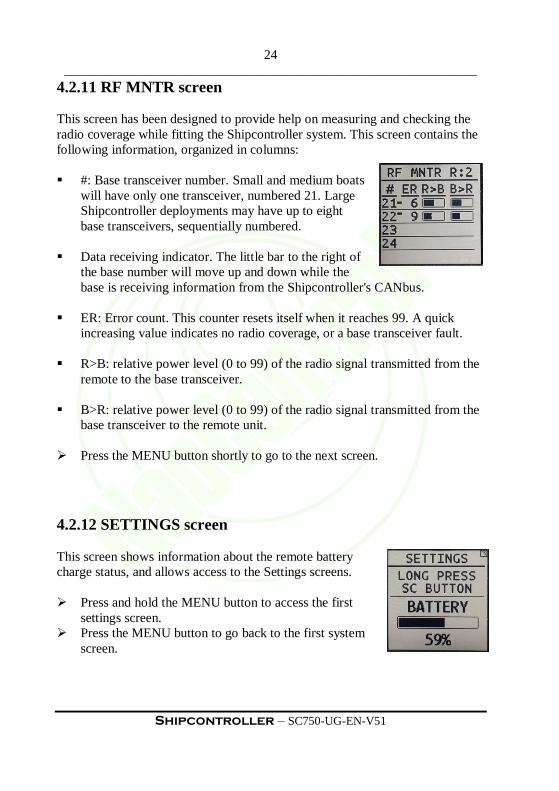
4.2.11 RF MNTR screen
This screen has been designed to provide help on measuring and checking the
radio coverage while fitting the Shipcontroller system. This screen contains the
following information, organized in columns:
#: Base transceiver number. Small and medium boats
will have only one transceiver, numbered 21. Large
Shipcontroller deployments may have up to eight
base transceivers, sequentially numbered.
Data receiving indicator. The little bar to the right of
the base number will move up and down while the
base is receiving information from the Shipcontroller's CANbus.
ER: Error count. This counter resets itself when it reaches 99. A quick
increasing value indicates no radio coverage, or a base transceiver fault.
R>B: relative power level (0 to 99) of the radio signal transmitted from the
remote to the base transceiver.
B>R: relative power level (0 to 99) of the radio signal transmitted from the
base transceiver to the remote unit.
Press the MENU button shortly to go to the next screen.
4.2.12 SETTINGS screen
This screen shows information about the remote battery
charge status, and allows access to the Settings screens.
Press and hold the MENU button to access the first
settings screen.
Press the MENU button to go back to the first system
screen.

25
______________________________________________________________
Shipcontroller – SC750-UG-EN-V51
4.3 Settings
In order to access the Settings screens and menus, navigate to SETTINGS
screen (see 4.2.9) and press the (+) and (-) buttons simultaneously.
4.3.1 SETTINGS 1 screen: Chain Calibration
This screen allows calibrating the chain length that matches
the boat's chain count sensor pulse.
Press the (+) button to increase the chain pulse
calibration value by 1 millimeter.
Press the (-) button to decrease the chain pulse
calibration value by 1 millimeter.
Press the MENU button to go to the next Settings screen.
The default calibration value is 399mm /pulse.
4.3.2 SETTINGS 2 screen: Depth alarm mode
The depth alarm feature of Shipcontroller allows raising a
visual and/or vibrator warning when the actual sounder
depth measure is below the alarm setting.
An NMEA water depth source and a suitable interface
adapter are needed to use this feature.
Press the (+) button to disable/enable the depth alarm feature.
Press the (-) button to change the alarm warn indication: only visual (a
screen indication) or visual + vibration alarm.
Press the MENU button to go to the next Settings screen.

26
______________________________________________________________
Shipcontroller – SC750-UG-EN-V51
4.3.3 SETTINGS 3 screen: Depth alarm level
This screen allows setting the depth, in meters to which the depth alarm will
arise. A water depth measure source and a suitable interface adaptor are needed.
Press the (+) button to increase the depth alarm setting
by 0.1m.
Press the (-) button to decrease the depth alarm setting
by 0.1m.
Press the MENU button to go to the next Settings
screen.
4.3.4 SETTINGS 4 screen: Thrusters Inhibition
This screen allows enabling or disabling the thruster's
inhibition feature. When enabled, the remote thruster
buttons will be disabled if the boat's speed is greater than
the selected inhibition speed.
If no speed data is received by the remote, this feature will
be inoperative, and the thruster buttons will become
enabled.
Press the (-) button to decrease the speed limit or disable this feature.
Press the (+) button to enable this feature or increase
the speed limit.
Press the MENU button to go to the next Settings
screen.

27
______________________________________________________________
Shipcontroller – SC750-UG-EN-V51
4.3.5 SETTINGS 5 screen: Autopilot screen enabling
This screen allows enabling or disabling the Autopilot Screen. If no autopilot is
available, the autopilot screen may be disabled in order to facilitate browsing
through the menus.
If autopilot functions are enabled, press the (-)
button to disable.
If autopilot functions are disabled, press the (+)
button to enable.
Press the MENU button to go to the next Settings
screen.
4.3.6 SETTINGS 6 screen: Enabling screens
In order to facilitate browsing through the menus, this
screen allows enabling or disabling various system
screens.
Press the SEL button to select the item you want to
change.
Press the SET button to enable/disable the
corresponding option.
Press the MENU button to go to the next Settings screen.

28
______________________________________________________________
Shipcontroller – SC750-UG-EN-V51
4.3.7 SETTINGS 7 screen: Auto Screen Change
This screen allows enabling or disabling the Auto Screen
Change feature. This feature allows to automatically moving
to the screen related to the buttons you are activating:
If you activate any of the engine controls or any of the
thruster controls, the screen will change to the
DOCKING screen automatically.
If you activate any of the windlass buttons, the screen will change to the
CHAIN COUNT screen.
If Auto Change is enabled, press the (-) button to disable it.
If Auto Change is disabled, press the (+) button to enable it.
Press the MENU button to go to the next Settings screen.
4.3.8 END SETTINGS screen
This screen allows to exit from the setting screens sequence,
and return to the main screens cycle.
Press the (+) button to exit settings and return to the first
system screen.
Press the MENU button to go to back to the first Settings
screen.

29
______________________________________________________________
Shipcontroller – SC750-UG-EN-V51
4.4 Engine control
4.4.1 Taking engine control
We refer here to the actions needed to "Take" engine control for the
Shipcontroller system. The exact "Take" procedure depends on the engine
interface adapter fitted and the actual electronic control system that the boat
has.
Please refer to your system manual to find indications on how to manage the
"Take" procedure for your Shipcontroller installation.
The SCR750 series remote control unit allows to:
Send a radio command from the remote unit to the Shipcontroller base
system to request engine control.
Display the "Take status" for the port and starboard engines to the user.
Depending on the boat's engine interface type and system configuration, the
engine control request procedure may be one of the following:
a) Manual control transfer from the remote unit: The user must navigate to the
ENGINES CTRL screen (See 4.2.2) and send a control request command to the
boat, by pushing the (+) button.
b) Manual control transfer from the ECU system: The user must use the ECU
switches or ECU control panel buttons in the boat to give engine control to the
Shipcontroller system.
c) Automatic control transfer: The Shipcontroller system is linked to the ECU
system, and it is capable of detecting when it can take the engine control, or
when it must inhibit the remote engine control.
d) Implicit control transfer: The Shipcontroller engine interface is linked to a
single control head, interoperating with its levers. The remote will have engine
control only when that control head has control.

30
______________________________________________________________
Shipcontroller – SC750-UG-EN-V51
4.4.2 Engine control signaling
If the Shipcontroller and ECU configurations allow provide
the control transfer status, the remote unit will indicate the
"Take" status in the following way:
a) When the remote has engine control for both the port and
starboard engines:
The green led is permanently on. (If there is radio
coverage and none of the buttons are pressed).
The NAV DATA screen changes its title to DOCKING.
The ENG CRTL screen shows "ON" for both engines.
b) When there is no engine control for any of the engines (but the radio
coverage is OK):
The green led will be flashing at a 1sec. rate (if there is radio coverage and
none of the buttons are pressed).
The DOCKING screen is replaced by the NAV DATA screen.
The ENG CRTL screen shows "OFF" for one or both engines.
If the boat system does not support the "Take" status signaling, the
Shipcontroller system will assume that it has engine control permanently.
4.4.3 Engine control priorities.
There are two types of engine controls in the remote unit front panel:
Membrane keyboard pushbuttons:
o Port ahead-fast and starboard ahead-fast.
o Port astern-fast and starboard astern-fast.
Toggle levers:
o Port slow ahead/astern lever.
o Starboard ahead/astern lever.

31
______________________________________________________________
Shipcontroller – SC750-UG-EN-V51
In the event that multiple engine controls are operated simultaneously for a
given engine, the system applies the following rules of precedence, in order:
The controls for each engine (Port and Starboard) are independent, and can
be activated simultaneously without any restrictions.
Ahead has priority over astern. For example, if the starboard engine fast
ahead and fast backward buttons are activated simultaneously, ahead
prevails.
Fast speed takes precedence over slow speed. If you operate, for example,
astern and fast astern buttons for the port engine, fast astern prevails.

32
______________________________________________________________
Shipcontroller – SC750-UG-EN-V51
4.5 Secondary systems control
4.5.1 Thrusters control
Press the Bow/Stern switch levers toward the green arrows (starboard) or the
red arrows (port), in order to achieve the corresponding thruster effect. These
controls can be used simultaneously without any limitations.
Usually, the Shipcontroller Bow and Stern Thruster controls are connected in
parallel with the same controls of the boat, so that both can be active, but should
not be used simultaneously.
You may operate the Thruster controls of the boat while Shipcontroller is on,
just do not operate the Shipcontroller remote unit thruster controls while doing
it.
If the Thrusters inhibition feature is enabled, the thruster controls in the remote
will emit a vibration when the boat speed is greater than the limit speed.
4.5.2 Windlass control
The system can be equipped with dual windlass control capability.
The main windlass is always selected after powering on the remote. If you want
to use the secondary windlass you must select it using the WINDLASS menu
(See 4.2.4).
The chain counter function is associated to the main windlass.
Press the UP/DOWN windlass buttons on the remote front panel for raising or
lowering the anchor, respectively.
If both buttons are pressed simultaneously, the UP button has priority.
You may operate the Windlass controls of the boat while Shipcontroller is on,
just do not operate the Shipcontroller remote unit windlass controls while
doing it.

33
______________________________________________________________
Shipcontroller – SC750-UG-EN-V51
4.5.3 Auxiliary control channels
These are multi-function buttons. If any action screen is active, the function of
these buttons is indicated in the last line of the screen, and the auxiliary control
channels are temporary inoperative.
When any informative screen is active, these buttons are operative:
"Light" button:
This button is configured as a toggle. Each time the button is pressed and
released, the output status changes from on to off, or from off to on. This
auxiliary output is usually connected to a light in the boat, but may be
connected to any other device.
"Horn" button:
This button is configured as a pushbutton. The control output will be active as
long as you hold down this button, and inactive when the button is released.
This auxiliary output is usually connected to the horn in the boat; buy may be
connected to any other device.

34
______________________________________________________________
Shipcontroller – SC750-UG-EN-V51
4.6 Battery charging
The SCR750 series remote control unit includes an internal rechargeable
battery, and a suitable battery charging circuit. The unit includes a micro-USB
connector to charge the battery and/or an optional internal Qi wireless charging
receiver.
In order to charge the internal battery:
1. Power-off the remote control unit.
2. If the unit has a micro-USB connector, plug a standard micro-usb 5VDC
charger and power the USB charger on.
3. If the unit has an internal Qi wireless charger, power on the charging
transmitter and place the remote unit on top of it, adjusting the remote unit
position until the charging led shows a red color.
4. Wait until the charging led changes its color to green or blue.
5. Disconnect the charger.

35
______________________________________________________________
Shipcontroller – SC750-UG-EN-V51
5 Technical Information
5.1 General
Dimensions:
Weight:
Operating temperature range:
IP rating:
125mm x 79mm x 40mm
159gr.
0ºC ~45ºC
IP65
5.2 Electrical
Power source:
Charging:
Internal Lithium Polymer 3.7V
rechargeable battery with protective
circuit.
Internal Qi wireless charging
receiver or USB micro AB
connector for a 5VDC/1000mA
charging source.
5.3 Radio subsystem
Type:
RF Band:
Max TX power:
Modulation Technique:
Range:
Bidirectional wireless data link
ISM 2.4GHz
10mW ERP
DSSS + Offset QPSK
< 500m Outdoor/Line of Sight
< 80m Indoor
MAC protocol
Addressing:
Data encryption:
Approvals:
IEEE 802.15.4
64-bit
AES, 128 bits.
CE (ETSI), FCC, C-TICK, IC, Telec.

36
______________________________________________________________
Shipcontroller – SC750-UG-EN-V51
6 Troubleshooting
Only common operating problems of the remote control unit SCR750 series are
indicated here. For a complete system troubleshooting list, please refer to the
Shipcontroller System Manual.
Symptom Possible Cause / Actions
When turning the remote on, red
and green indicators blink a few times, and then both turn off.
The diagnostic system has detected a fault in
the remote control. Contact your service
representative.
Remote control unit will not turn
on. Exhausted battery. Recharge.
System Damage. Contact your service
representative.

37
______________________________________________________________
Shipcontroller – SC750-UG-EN-V51
7 Warranty Information
SHIPCONTROLLER WARRANTY
All Shipcontroller Systems are guaranteed to be free from manufacturing
defects in material and/or workmanship for two years from original date of
purchase. The warranty covers only the repair or replacement of defective
equipment or parts.
Shipcontroller warranty will be void if any part of the system shows signs of
having been tampered with or disassembled, beyond the operations needed for
the installation and maintenance.
The installation, calibration, and removal of the system must be performed by
an authorized technician. Otherwise, the warranty may be voided.
Any costs of secure transportation of the product to and from the Shipcontroller
service centre will be borne by the customer.
THIS WARRANTY DOES NOT COVER:
Any damage, failure or loss caused by abuse, neglect, improper repair,
improper maintenance or installation, alteration, modification, failure to
follow instructions or warnings in the owner’s manual, use outside the
operating ranges, or other abnormal excessive, or improper use.
Any damage, failure or loss caused by accidents, natural disasters, or other
force majeure, or caused by water due to improper use.
Contact Information:
Naocontrol, S.L.
Félix Acevedo, 1, 6º D2
15008 A Coruña
SPAIN

38
______________________________________________________________
Shipcontroller – SC750-UG-EN-V51
NOTES

39
______________________________________________________________
Shipcontroller – SC750-UG-EN-V51
www.naocontrol.com