Embed Size (px)
Citation preview
India Ports Global Pvt Ltd
1 IPGPL/CHE/2016/001/Final
Ship to Shore Container Gantry Crane
(Four units for ShahidBeheshtiPortChabahar))
Technical Specification
November, 2016

India Ports Global Pvt Ltd
2 IPGPL/CHE/2016/001/Final
CONTENTS
PART 1 - GENERAL 1.1 Introduction 1 1.2 Sub-Contractors and Suppliers 1 1.3 Materials 1 1.4 Environmental Conditions 1 1.4.1 Temperatures 1 1.4.2 Relative Humidity 1 1.4.3 Rainfall 1 1.4.4 Winds 2 1.4.5 Seismic 2 1.5 Description of the Crane 2 1.6 Principle Dimensions and Loads 3 1.7 Standards 4 1.8 Classification 4 1.9 Interfaces with Civil Works 5 1.10 Drawings and Documents for Approval 5 1.11 Inspection and Testing During Manufacture 7 1.12 Training 8 1.12.1 Crane Operation Training 8 1.12.2 Maintenance Staff Training 9 1.13 Maintenance Tools and Equipment 10 1.14 Drawings and Documents for Maintenance 10 1.15 Packing for Transportation 11 1.16 Labelling 11 1.17 Dangerous Materials 12 1.18 Inspection and Testing at Site 12 1.18.1 Acceptance Testing 12 1.18.2 Durability Test 13 1.19 Compliance with Technical Specification 13
1.20 Spares 13 PART 2 – STRUCTURAL
2.1 General 15 2.2 Stairs, Ladders, Walkways and Platforms 15 2.3 Welding 16
2.4 Painting and Protective Treatments 17
PART 3 – MECHANICAL
3.1 Main Hoist 18 3.2 Trolley Travel 18 3.3 Gantry Travel 19 3.4 Boom Hoist 20 3.5 Headblock, Spreaders &Hookblock 22 3.6 Spreader List, Trim and Skew 24 3.7 Anti-Sway System 24

India Ports Global Pvt Ltd
3 IPGPL/CHE/2016/001/Final
3.8 Operator’s Cabin 25 3.9 Checker’s Cabin 27 3.10 Boom Operator’s Cabin 27 3.11 Machinery House 27 3.12 Electric Room 29 3.13 Personnel Lift 30 3.14 Fire Extinguishers 31 3.15 Rope Drums 31 3.16 Wire Ropes 32 3.17 Sheaves 33 3.18 Hydraulic Systems 33 3.19 Gear Reducers 34 3.20 Bearings 34 3.21 Castings 34 3.22 Bolts and Nuts 35 3.23 Grease Lubrication Systems 35 3.24 Crane Wash-down System 36
3.25 Couplings 36
PART 4 - ELECTRICAL 4.1 Power Supply 37 4.2 Low Voltage Switchboards and Motor Control Centres 38 4.3 Electrical Installation Standard 39 4.4 Earthing and Bonding 39 4.5 Wiring 39 4.6 Cabling to Trolley 40 4.7 Trailing Cable Reel System 41 4.8 Limit Switches 42 4.9 Fuses 42 4.10 Motors 42 4.11 Variable Speed Drives and Control Systems 43 4.12 Transformers 46 4.13 Sequence Control 46 4.14 Interlock and Safety Devices 47 4.15 Instrumentation 48 4.16 Telecommunication 48 4.17 Electrical Supply Outlets 49 4.18 Safety Warning Devices/Emergency Stop Push Buttons 50 4.19 Lighting 51 4.20 Covers, Junction Boxes and Enclosures 52 4.21 Container Positioning System 52 4.22 Emergency Power Supply 52 4.23 Crane Management System 52
4.24 PLC System 53
Appendix A- List Of Manufacturers (LOM)

India Ports Global Pvt Ltd
4 IPGPL/CHE/2016/001/Final
PART 1 - GENERAL 1.1 Introduction
This Specification is for the design, manufacture, delivery, installation, commissioning and testing of four units of Ship to Shore Container Handling Cranes for ShahidBeheshti Port (Chabahar), Islamic Republic of Iran. The cranes shall be electrically powered and will be used for the loading and unloading of container vessels, approximately 8,600 TEU capacity.
1.2 Sub-Contractors and Suppliers
Any Sub-Contractor proposed for the crane structure fabrication work shall be
subject to Buyer approval.
The name of proposed manufacturers of major component items shall be
stated in the Technical Specification with regard to the attached List Of
Manufacturers (LOM).
Approved Sub-Contractors and suppliers shall not be changed following award
of the Contract without the Buyer’s approval. 1.3 Materials
ShahidBeheshti Port (Chabahar) is located in a highly corrosive marine
environment. Due consideration shall be given to the design and selection of
materials used for the crane and its component parts.
Where stainless steel is used in an exposed location, it shall be grade 316S16
or equivalent. Grades with less resistance to corrosion shall not be used
without explicit approval from the Buyer. 1.4 Environmental Conditions
The port equipment will be exposed to an extremely corrosive marine
atmosphere with particularly high salinity, high temperatures and humidity. In
addition, these regions of the Persian Gulf and Oman sea are subjected to
frequent dust and haze storms and periodic seismic activity.
The Manufacture shall design and construct the cranes to ensure reliable
operation under the following site conditions: -
1.4.1 Temperatures (measured in shade)
Ambient Air Temperatures: Maximum 50°C
Minimum 0°C
1.4.2 Relative Humidity
Maximum relative humidity (RH) 99%
1.4.3 Rainfall
Mean annual (17 years) 171mm
Max annual (1976) 494mm
India Ports Global Pvt Ltd
5 IPGPL/CHE/2016/001/Final
Min annual (1962) 1mm Intensity 20mm/20 min
1.4.4 Winds
Wind strength and direction variable through the seasons:
Maximum operating wind speed 20m/s Maximum storm winds 44m/s (gust)
1.4.5 Seismic
Seismic Design Data (minimum values): Horizontal acceleration (50 year) 0.34g
Vertical (50% x horizontal) 0.17g 1.5 Description of the Crane
The crane shall be a post-panamax, rail mounted ship-to-shore container
handling crane with an elevating boom that can be raised to clear a ship’s structure and travel clear along the berth. The boom shall be raised and
locked in a nearly vertical position for storage. The crane shall be electrically powered from a 20 kV, 50HZ mains supply. The trolley shall be self- driven.
The crane shall be capable of working with the boom in the raised or lowered
positions.
The crane shall be capable of handling 20ft,40ft, and 45ft containers (9ft
6inches high) up to 65 tons under spreader (twin lift conditions).
Each crane shall be equipped with a separating twin lift spreader, capable of
handling two 20ft containers end to end with various standard gaps, or single
ISO containers as indicated above.
The Manufacturer shall also supply spare single lift telescopic spreaders
suitable for handling above containers, one unit 85t heavy lift cargo beams
incorporating ram shorn hook with safety catches and one unit telescopic over
height frames (TOF).
The crane shall under normal operation be capable of
simultaneousmovements e.g. hoist & trolley travel at the same time or gantry
travel &

India Ports Global Pvt Ltd
6 IPGPL/CHE/2016/001/Final
trolley travel at the same time. Simultaneous operation of all movements i.e.
hoist, trolley and gantry shall also be possible but at reduced speed. The
crane shall be fitted with an anti-sway system and be able to trim, list and
skew containers. The crane shall also be equipped with a hydraulic snag load
protection system and incorporate anti-lift devices to prevent the trolley from
leaving the track and falling from the crane.
The crane structure and mechanisms shall be based upon designs that have
been proven in service. The crane electrical drive systems and equipment
shall be of proven design for use with high speed container handling cranes,
and obtained from a Sub-Contractor who has an extensive track record in the
crane industry.
The crane shall be capable of manual and semi-automatic control, and
provided with a computerized crane diagnostics monitoring system.
1.6 Principal Dimensions and Loads
Portal clearance height 13.0 metres minimum
Height of lift above top surface of gantry rails (to underside of spreader)
35 metres
Depth of lower below top surface of gantry Rails 18 metres
Outreach (seaside rail to centre of trolley) 50 metres(to suit 18 box wide ships)
Backreach (land-side rail to centre of trolley) 24.0 metres
Gantry rail span 35 metres
Overall crane length (along track). Minimum consistent with good stability
Safe working load under spreader (Twin lift) 65 tonnes
Safe working load under heavy lift hook. 85 tonnes(restricted outreach &speed accepted)
Maximum hoisting speed (with 65t load) 90.0 m/ minute
Maximum hoisting speed (empty spreader) 180.0 m/ minute
Maximum trolley travel speed 210.0 m/ minute
Maximum gantry travel speed 45.0 m/ minute
Time for one complete boom hoisting or lowering cycle
6 minutes maximum

India Ports Global Pvt Ltd
7 IPGPL/CHE/2016/001/Final
1.7 Standards
The major design standards to be used for the design of the crane shall be: -
British Standards:
BS 2573: Rules for the design of cranes: Part 1: Specification for
classification, stress calculations and design criteria for structures
BS 2573: Part 2: Permissible stresses in cranes and design rules: Mechanisms
OR Federation Europeenne De La Manutention (FEM) - Rules for the design of hoisting appliances
Seismic qualification of cranes shall be in accordance with the latest
Japanese standards.
The materials, workmanship and component standards to be used shall be
British Standards or DIN standards or other equivalent standards specified or
approved at the time of placement of the order for the cranes. 1.8 Classification
The crane shall be designed to work continuously, up to a maximum of 24
hours a day at peak, and to work in a service design wind speed of 20m/sec
as defined in the BS 2573.
Structures shall be classified to BS 2573 as follows: i) Class of Utilization - U8 (4 million loading cycles) ii) State of loading - Q3 iii) Group Classification - A8 iv) Impact factor - 1.4
v) Duty factor - 0.9
The details of the load and load cycle to be used in the fatigue check shall be
submitted at the time of tendering.
Mechanisms shall be classified to BS 2573 as follows:
Mechanisms Class of State of Group Classification
Utilization Loading
Hoist T8 L3 M8 Traverse (Trolley) T8 L3 M8 Travel (Gantry) T5 L4 M7
Boom Hoist T3 L4 M5

India Ports Global Pvt Ltd
8 IPGPL/CHE/2016/001/Final
1.9 Interfaces with Civil Works
The rails shall be of type A 120 DIN 536 and the supply of them is excluded
from the scope of this tender.
Quay edge to seaside rail shall be 3m. Fender width shall be 1.5m approx. (to
be confirmed by Buyer prior to Contract award).
Sea levels in metres above chart datum are as follows: MHHW: 3.30. MLLW:
0.70. MSL: 2.30. Quay Level will be +3.2m according to MSL.
The design value for the vertical uniformly distributed load allowed on the rails
is 65t/m with a maximum vertical point load of 80t. The design lateral load on
the rails is a UDL of 5t/m.
The theoretical weight and maximum wheel loads for the crane shall be
entered in the Technical Questionnaire.
The crane shall be supplied complete with end of track buffers, storm anchor
sockets and cable connection pit equipment such as funnel, anchor drum,
cable joint box and accessories. Cable connection pit equipment shall be in
stainless steel unless otherwise approved.
The cable slot shall be adjacent to the seaward rail and the cable reel shall be
at high level in a location where the possibility of collision damage is
minimized.
The length of cable provided with the crane shall be sufficient for up to 300
metres (to be confirmed prior to Contract award) of crane travel to either side
of the cable turn over pit. 1.10 Documents and Drawings for Approval
The Manufacturer shall submit the following documents and drawings to the Buyer for approval. Unless otherwise agreed by the Buyer, documents and drawings shall be supplied in four (4) full size paper copies (sizes A0, A1, A2, A3 or A4 as appropriate) plus electronic format (Microsoft office or AutoCAD as necessary). The Buyer shall reply with review / approval comments within a period of four (4) weeks from receipt of paper copies unless otherwise stated in the Contract. Where information submitted to the Buyer is found to be incomplete, the 4 weeks approval period shall commence upon receipt by the Buyer of the additional drawings and documents requested. Where no submission dates are stated below, these shall be in accordance with dates agreed by the Buyer and indicated in the Manufacturer’s Work Schedule: -
• Within 5 days from Contract award the Manufacturer shall submit for the
Buyer’s approval a comprehensive Work Schedule (programme) in the
form of a Gantt chart listing all major milestones and detailing all design,
manufacturing, testing, delivery, erection and commissioning activities.
• Within two weeks from Contract award the Manufacturer shall submit for the Buyer’s approval a preliminary Contract Quality Plan, outlining QA procedures covering all project management, design, manufacturing

India Ports Global Pvt Ltd
9 IPGPL/CHE/2016/001/Final
and testing processes, including those undertaken by the Sub-Contractors and major suppliers. The Manufacturer shall confirm contact names of the project manager and others who will communicate with the Buyer or the Buyer’s Representatives on matters relating to technical or commercial aspects of the Contract.
• The Manufacturer shall submit proposed arrangement and detail
drawings. These shall include the crane GA with overall dimensions, main structure, spreaders, headblock, access-ways, mechanisms, anti sway system, TLS system cylinders and locations, anti-collision system, machinery house including all machinery layouts, re-reeving system and maintenance crane hook approach, trolley arrangement including motors and locations, gantry drives including motors and locations, rail clamps, electric room, operator’s cabin, control consoles, layout of controls, checker’s cabin, passenger lift, lighting, electrical schematic and single line diagrams.
• The Manufacturer shall submit calculations in sufficient detail to allow a
complete review of the design to be carried out. As a minimum, this
shall include calculations for structure, stability, wheel loading,
mechanisms, gear reducers, buffers, storm anchors, motor power, and
power demand.
• Procurement specifications defining all technical aspects of major
proprietary items as agreed within the Contract Quality Plan.
• Painting specifications for structure and machinery.
• Detailed manufacturing inspections plans for all major assemblies and
items agreed within the Contract Quality Plan. These shall list all
relevant inspection activities including welding acceptance and NDT
standards applicable.
• Preliminary packing specification, delivery and erection schedules are to
be submitted a minimum of four weeks prior to manufacture
commencing.
• Steel mill certificates showing source, grade, composition and strength.
• Works test and inspection reports for welding and painting etc.
• Overload test certificates for lifting components such as spreaders, wire
ropes, twistlock pins, hook block etc.
• Operating and Maintenance Manuals including brochures/catalogues for
the mechanical and electrical components.
• Test certificates for motors, hydraulic components etc.
• Training plan.
• Site erection and testing procedure.
Documents and drawings shall be produced specifically for this project and
shall be suitably titled as agreed by the Buyer prior to Contract award.

India Ports Global Pvt Ltd
10 IPGPL/CHE/2016/001/Final
1.11 Inspection and Testing During Manufacture
The Manufacturer shall submit for the Buyer’s approval, four weeks prior to
commencing manufacture, full details of their proposed inspection and test
programme(QC Plan including Tests, witness and hold points). This shall
include all tests to be carried out prior to delivery by the Manufacturer and
Sub-Contractors as specified in the Contract and any further tests proposed
by the Manufacturer. The scope of inspections to be carried out by a third
party inspector to be appointed by the Buyer shall include, but not necessarily
be limited to the following: -
• Conduct visual checks on the quality of incoming materials, which
include structural steel, motors, reducers, hydraulic components and
other items deemed necessary by the Buyer.
• ITP (Inspection & Test Plan) and QC Plan shall be approved by the
buyer.
• Verification and identification of steel material, including witness of
fracture test against mill sheets for major structural items. Review
system for material tracing with random witness of identification transfer.
• Check welders test certificates and welding procedures to ensure that
only qualified welders are being used and that correct welding
procedures are followed.
• Check material preparation, cutting, fit-up and welding to ensure that
they are in compliance with drawings.
• Review qualifications of non-destructive examination operators and
procedures. Witness non-destructive examinations of ultrasonic,
magnetic particle and liquid penetrant testing as required. Review
radiographs.
• Conduct visual inspections pertaining to the quality of structural welding.
• Witness low-pressure testing of fabricated box sections to confirm that
air tight structures are produced.
• Compare assembly and mounting of mechanisms with recognized
engineering practices.
• Check material surface preparation and coating of paint. Check proper
application of paint to meet specifications. Check ambient conditions
and/or records during blasting and painting.
• Check electrical wiring for proper installation and termination. Witness
high voltage withstand and insulation resistance tests.
• Witness shop test of motors, reducers, hydraulic systems and
subassemblies.
• Witness overload test for brakes.
• Review Dynamic load test reports for motors.

India Ports Global Pvt Ltd
11 IPGPL/CHE/2016/001/Final
• Witness tests on the crane and spreaders prior to shipment. Witness
tests on control panel and drive systems.
• Conduct final checks on the quality of welds, painting, installation of
substructures, sea-fastenings, etc. before the crane is shipped out to
the site.
Costs associated with Buyer’s Representatives, including accommodation and travel expenses shall be paid by the Tenderer. The Tenderer shall make provision for a specified number of separate inspection visits, each with a specified duration and attended by a specified number of Buyer’s representatives (for tests outside I.R.Iran). For tests inside I.R.Iran, date and duration of each test shall be defined by the Buyer.Further to the above. All the related costs associated with full time inspection of a specified number of Buyers engineers (supervisors) from the beginning of the Manufacturing stage to the end of commissioning and test stages at the workshop or site shall be paid by the Manufacturer (Tenderer). All the required facilities such as proper office with related desk and cabinets, air conditioning, direct telephone line, fax service, PC and internet shall be provided for the said Buyer’s Representatives.The number of supervisors and inspection periods are specified in the commercial part of the contract documents.
1.12 Training
Training shall be provided to the crane operators and maintenance staff by competent instructors in the Farsi language by help of expert translators, unless otherwise agreed and approved by the Buyer. The program for training at the Manufacturers works and at site shall be drawn up by the Manufacturer and approved by the Buyer
. 1.12.1 Crane Operator Training
Crane operator training of a specified number of people shall be undertaken
at site, and shall cover, but not necessarily be limited to the following: -
• Familiarization with controls, operating systems, instrumentation,
equipment and fittings.
• Daily routine maintenance.
• Understanding the crane’s capability, safety features and operational
techniques.
• Practical instruction on an operating crane.
1.12.2 Maintenance Staff Training
The Training Plan shall include training at the Manufacturer’s or Sub-
Contractor’s works of a specified number of people appointed by the Buyer
and training at site in accordance with programme approved by the Buyer.
Accommodation, subsistence and travel expenses for works training of the
following number of Buyer’s engineers shall be paid by the Manufacturer: -
• Training of a specified number of mechanical and hydraulic engineers at
the Manufacturers works, each for a specified period.

India Ports Global Pvt Ltd
12 IPGPL/CHE/2016/001/Final
• Training of a specified number of electrical engineers at the Manufactures
works each for a specified period.
• Training of a specified number of electronic engineers at the
Manufacturers works each for a specified period.
Maintenance staff shall be trained to use fault diagnostic aids, special tools,
jigs, instruments and wear gauges to calibrate crane components and to carry
out major repairs and maintenance jobs.
The training shall cover, but not necessarily be limited to the following:
a. Familiarisation with main components and systems comprising:
• mechanical system • drive system • electrical system • spreaders • diagnostics systems
b. Routine maintenance program
• Periodic checks and servicing • Lubrication program
c. Trouble shooting, special adjustments and repairs
d. Familiarization with manuals and parts book.
The number of trainees and training periods are specified in the commercial
part of the contract documents.
1.13 Maintenance Tools and Equipment
The crane shall be supplied complete with all necessary maintenance tools
and equipment including the following:
• Wear gauges to indicate the limits of wear on rope sheaves, rope drums,
trolley wheels, etc.
• Two high voltage testers, multimeter and tong ammeter.
• One control panel to test spreader operation in the workshop during
maintenance. The panel shall incorporate push buttons, selector switches,
indicator lamps, programmable logic controllers, input/output devices,
spreader multi-pin plug with cable, and all parts necessary to operate and
confirm proper operation of all spreader functions. Power supply cable of
at least 20 metres shall be provided with the panel.
• Two infra-red non-contact thermometers for checking the operating
temperatures of equipment. The infra-red thermometers shall be equipped
with laser sighting to accurately pinpoint the target where temperature
measurements are required.
India Ports Global Pvt Ltd
13 IPGPL/CHE/2016/001/Final
• Two complete sets of mechanical tools including ring spanners, sockets,
hammer, adjustable spanners, screw drivers, pliers etc., complete with
tool box.
• Two pressure gauges complete with hoses and quick-action couplings for
checking the pressure of hydraulic systems.
• Two hydraulic oil flow meters to check and calibrate the flow of hydraulic
systems.
• One hydraulically operated high torque set complete, for loosening nuts
and bolts.
• Mobile equipment complete for jacking-up the crane.
The Manufacturer shall include for any necessary training to be given to the
maintenance staff on the use of the above equipment in his Training Plan. 1.14 Drawings and Documents for Maintenance
Copies of the following shall be submitted to the Buyer for approval in
advance of training the operators and maintenance staff: -
• Crane operators’ manual.
• Maintenance and repair manual. The documentation shall include relevant
software for preventative maintenance.
• Complete set of as-constructed drawings covering all aspects of the
structural, mechanical, electrical, and hydraulic parts of the crane.
• Complete set of electrical and electronic circuit diagrams. Computer
hardware layout schematics and detailed circuit diagrams to be illustrated
in sufficient detail to enable them to be used for repair and maintenance.
• Computer software documentation.
• Spare parts manual and drawings. Spares used on the crane shall be
indicated in the spare parts manual with drawings. These shall include the
Manufacturer’s and the original component Sub-Contractor’s part
numbers and descriptions.
Note:The quantity of above mentioned items should be clarified in the contract. 1.15 Packing for Transportation
The Manufacturer shall submit for the Buyer’s approval at least four weeks prior to commencing manufacture, the proposed packing specification,
together with preliminary delivery / shipping and erection schedules. Delivery
and erection schedules shall include details of programmed dates for all activities as derived from the Manufacturer’s approved Work Schedule. At
least four weeks before shipment of each consignment, the Manufacturer shall inform the Buyer of final packing lists including all details specified in the
Contract.
Plant likely to deteriorate due to the weather shall be suitably protected during
the programme of the works and particularly during transit and site erection.

India Ports Global Pvt Ltd
14 IPGPL/CHE/2016/001/Final
Before delivery, plant shall be properly packed and prepared for export. Plant
shall be thoroughly dried and cleaned internally. External unpainted ferrous
parts and machined surfaces shall be protected by an approved proprietary
preservative, all openings shall be covered and all screwed connections shall
be protected unless otherwise agreed.
Where moisture absorbent materials have been used for protection against
corrosion during storage or transit, adequate information of their location and
warning as to their removal shall be clearly indicated.
Adequate precautions shall be taken in the packing of plant that has ball or
roller bearings so as to eliminate the risk of damage to such bearings during
transit. 1.16 Labelling
Labels and nameplates shall be permanently engraved or embossed, in
English, on phenolic plastic or non-ferrous, rust proof plates and mounted
securely by corrosion resistance fasteners at easily visible locations.
Nameplates and labels shall not be easily removable.
Warning signs and safety notices shall be in both Farsi and English and shall
conform to the associated EU regulations. The translated text in Farsi shall be
subject to the Buyer’s prior approval.
Layout and content of Crane nameplates shall be subject to Buyer’s approval.
For major components such as motors, reducers and the like, nameplates
from the original equipment manufacturer shall be attached to the
components. Nameplates shall bear the model and serial numbers, year
andplace of manufacture, ratings, ratios, bearing identification number, safety
warnings, maintenance limits and any other information critical to the
components.
Nameplates indicating the function or service of contactors, circuit breakers,
hydraulic valves, limit switches, etc. shall be provided. Plates showing
hydraulic circuit diagrams shall be provided on all hydraulic units. Electrical
panels and junction boxes shall be provided with electrical connection
diagrams with functional descriptions corresponding to the wire/cable
numbering for easy troubleshooting.
A plate showing principal dimensions, speeds and capacity of the crane shall
be fitted in the operator’s cab. 1.17 Dangerous Materials
The crane shall be free from any parts and components made of or containing
asbestos.
The crane shall not contain any flammable parts and components except for
lubricants.
The crane shall be free from any substances that are to be phased out as
stipulated by the Montreal Protocol of 1987, e.g. CFC (Chlorofluorocarbon).
India Ports Global Pvt Ltd
15 IPGPL/CHE/2016/001/Final
1.18 Inspection and Testing at Site
Inspection and testing shall be in accordance with procedures approved by
the Buyer. The Manufacturer shall submit details of proposed site inspections
for approval at least four weeks before erection commences. Where proposed
tests are not acceptable to the Buyer, the Manufacture shall modify the test
procedures in accordance with the Buyer’s requirements. Inspection shall be
undertaken before testing. The inspection shall include visual inspection of
the completed installations and protective painting systems. 1.18.1 Acceptance Testing
The Manufacturer shall submit a detailed test procedure for approval at least
four weeks before testing is due to commence. The Manufacturer shall
provide the testing facilities including power supply, instruments, tools and
test container. If any of the tests fail, the Manufacturer shall, in accordance
with the Contract, remedy the defects and repeat the test to the satisfaction of
the Buyer.
The tests shall include no load and full load tests on the mechanisms to check
the performance characteristics are in conformance with the Contract
specifications. Measurement of noise levels, lighting levels, structural
deflections, anti-sway system performance, harmonic disturbances etc. shall
also be carried out.
Vibration tests of the structure, operator cabin and trolley shall be carried out
and results recorded at the complete range of operating speeds and loads.
Consideration shall be given to the requirements of BS 6841: 1987 – ‘Guide
to the measurement and evaluation of human exposure to whole-body
mechanical vibration and repeated shock’ for which a certificate, confirming
compliance shall be provided.
The crane shall be tested in accordance with FEM standard, including no
load, the safe working load and dynamic 110% overload in that order before
the following durability test. In addition, a static overload test of 125% shall be
applied at mid span with the structural deflections recorded. 1.18.2 Durability Test
Upon completion of the inspections and acceptance tests, the crane shall be
subjected to a durability test in accordance with procedures approved by the
Buyer. The test shall include putting the crane into intensive use in actual
container operation for a period of 48 hours, or subjecting the crane to
continuous simulated container operation with the rated load at 30 lifting
cycles per hour up to a minimum of 600 cycles. The test shall be performed
by the Manufacturer with his own crane operator or with buyer crane operator.
During the first 10 hours of durability test, failures are allowed provided the
time for one single failure does not exceed 15 minutes. If the permitted single
failure time is exceeded, the test shall be restarted. Where the sum of failure
times reaches one hour, the testing time shall be extended by an hour.
Between the 11th and 24th hour of testing, short interruptions of up to 5
minutes each are allowed but where the sum of interruptions reaches 30
minutes, the testing time shall be extended by one hour. During that hour, no
India Ports Global Pvt Ltd
16 IPGPL/CHE/2016/001/Final
further interruptions are allowed.
The final 24 hours of testing shall be performed without interruption. In the
event an interruption due to crane malfunction occurs, the test shall be
continued until 24 hours of interruption free operation is achieved.
When final 24 hours of the durability test has been successfully performed,
the Manufacturer’s commissioning engineer shall ensure that faults have
been eliminated and any necessary repairs carried out to the satisfaction of
the Buyer.
There shall be separate durability tests for gantry travel and boom hoist. The
boom hoist test shall comprise five complete cycles in 1 hour maximum. 1.19 Compliance with Technical Specification
This specification does not cover all details of the crane and nothing written or
implied in this specification shall release the Manufacturer from providing a
complete working crane that is fully operational, safe and suitable for the
purposes of container handling. 1.20 Spares
Spare parts shall be excluded from the Contract price; however, a
comprehensive list of all spares parts complete with prices shall be submitted
with the tender.
A priced list of spare parts recommended by the Manufacturer to cover 12000
running hours shall also be submitted with the tender. The parts shall
includeconsumable parts that require frequent replacement and electrical
components such as fuses, lamps, relays, contacts, coils etc shall also be
identified.
Spares shall be indicated in the spare parts manual with drawings as
necessary. These shall include the Manufacturer’s, and the original
component Sub-Contractor’s part numbers complete with descriptions and the
quantities fitted to each crane.
India Ports Global Pvt Ltd
17 IPGPL/CHE/2016/001/Final
PART 2 – STRUCTURAL 2.1 General
Structural steel shall be to BS EN10113 Grades S275N or S355N or equivalent. Steel shall be supplied with mill certificates for mechanical
properties and chemical analysis. The Manufacture shall provide additional verification of quality requirements, including supplementary NDT and
destructive tests as approved by the Buyer.
The structure shall be of the rigid type to minimize swaying. Pin joints in the
main frames shall not be used, and where used elsewhere, shall not promote
rocking of the structure.
The crane structure shall be designed to withstand earthquake loads in
accordance with the Japanese Building Code for seismic zone applicable to
the site. The code shall be used for determining the seismic acceleration.
The crane structure shall be designed for working on out of tolerance rails as
follows: -
• Across track (between rails) +/- 10mm. • Along track accuracy of each rail relative to datum +/- 5mm.
• Level accuracy of each rail relative to datum +/- 25mm.
The crane structure shall be designed to avoid water being trapped in
corners, recesses or pockets. Splice joints shall be avoided and
counterweights will not be approved.
The design of the boom hinge pins, bogie pins, bracing pins, stay pins,
tension bar pins etc., shall be such that the pins shall last the whole life of the
crane. The allowable bearing stress of pins shall not exceed 0.3 times the
yield stress of the material. Pin joint bearing surfaces shall be enlarged to
minimize wear on the pins and bearing surfaces.
Means shall be provided on the boom, girder, top of mast and back reach for
the lifting of rope sheaves and other associated mechanism components. 2.2 Stairs, Ladders, Walkways and Platforms
Stairs, ladders, walkways and platforms shall be designed and constructed in
accordance with, BS 5395 Part 3. Stairs are preferred over ladders and shall
be utilized wherever practicable. Ladders however may be incorporated into
the cranes where stairs cannot be accommodated and subject to prior
approval by the Buyer.
No part of the stairs shall protrude into the area of container handling and
transport under the portal between the crane legs. Stairs for safe access to
the operator’s cabin and machinery house shall be mounted landside of the
landside legs. Walkways along the boom and girder shall be unobstructed
and as far as possible be at the same level. Walkways shall be provided
around the machinery house.

India Ports Global Pvt Ltd
18 IPGPL/CHE/2016/001/Final
Hot dip galvanized gratings shall be used for the walkways and platforms
used for inspection purposes, together with all exposed access stairs, ladders
and hand railing. Provision shall be made for the gratings to be easily
removable. Chequer plate shall not be used for stair treads.
Chequred plates of at least 4.5 mm thick shall be used for platforms where
maintenance works are undertaken. Design load for walkways and platforms
shall be 5.0 kN/m2 uniformly distributed load (UDL).
Access ways and permanent platforms shall be provided at areas on the
structural frame that require regular or periodic inspection. Platforms shall
also be provided on the trolley to facilitate inspection of the boom and girder
structures. Platform/s shall be provided at the end of the back span for
cleaning and maintenance around the exterior of the operator’s cabin. 2.3 Welding
Welding shall be undertaken in accordance with BS EN 1011-2:2001
Recommendation for welding of metallic materials. Alternative internationally
recognized standards such as AWS D1.1 shall be employed, subject to prior
approval by the Buyer.
Welding shall be undertaken by welders who are certified according to BS EN
287-1:1992 requirements. Welding procedure qualification tests shall be
carried out for all welding positions employed in the fabrication process,
according to BS EN 288-3:1992. Valid welder’s qualification certificates and
all welding procedures shall be reviewed and approved. Reports of such test
and welder’s certificates shall be submitted for review prior to fabrication.
As far as possible, welding shall be carried out by automatic or semiautomatic
process. Electrodes used for the main structures shall have tensile strength
greater than that of the steel material.
Precise details and extent of proposed non-destructive tests and the
standards of acceptance shall be submitted for the Buyer’s approval.
Weld testing shall be in accordance with the following standards or approved
equivalent:
BS EN 970: Visual Inspection BS 6072: Magnetic Particle flaw Testing BS EN 1714: Ultrasonic Testing BS EN 1435: Radiographic Testing.
All fabricated box sections shall be air tight and Nitrogen Gas to be inserted to
prevent ingress of water and subsequent corrosion. Low-pressure tests shall
be carried out to ensure that this is achieved.

India Ports Global Pvt Ltd
19 IPGPL/CHE/2016/001/Final
2.4 Painting and Protective Treatments
The recommendations of BS 5493 Code of Practice for “Protective Coating of
Iron and Steel Structures against Corrosion” and BS EN ISO 12944 shall be
followed.
Protective systems shall be compatible with C5-M corrosivity category,
suitable for coastal and offshore areas with high salinity. Unless otherwise
stated all protective coating systems shall have a life to first major
maintenance of 15 years. Details of the proposed paint system shall be
submitted for the Buyer’s approval.
Minimum blast cleaning standard shall be SA2.5, and minimum paint
thickness 270 microns dft. The paint system shall be applied in a minimum of
three coats by the air-less spray method and be overcoatable. Internal
surfaces of non-sealed, accessible box sections shall be suitably protected
from corrosion. Typically, this may be a similar paint system to the external
surfaces, with a thicker intermediate coat but excluding the final decorative
coat.
Blast cleaning and painting shall be undertaken in a dedicated under roof
facility where the environment shall be controlled and recorded. Paint shall
not be applied when the temperature is below 5° Celsius or the relative
humidity over 75%. Work not undertaken under suitable conditions of
temperature and relative humidity will be rejected. Grit blast material shall be
regularly checked and replaced with new to ensure correct profile height for
subsequent paint key.
Steelwork for stairs, access ladders, handrailing, platforms etc., shall be hot
dip galvanized. Due to the extremely corrosive nature of the atmosphere, a
thicker coating than normal is required. This shall be achieved by batch hot
dip galvanizing by a member of Galvanizes Association to BS EN ISO 1461:
1999 after grit blasting to SA2.5 with G24 chilled angular iron grit to achieve a
nominal thickness of 120 microns for steel thickness greater than 6mm.
Except where otherwise approved, all steel shall be galvanized after sawing,
shearing, drilling, punching and machining work has been completed. The
zinc coating shall be smooth, clean, of uniform thickness and free from
defects.
Finished colours and details of the Port or Terminal Operator’s Logo will be
advised after the award of Contract
Capacity signs showing the safe working load of the crane shall be fitted to
both sides of the gantry structure and shall be clearly legible from ground
level.
After erection, the Manufacturer shall repair to the original standards all paint
works damaged during the course of shipment and erection.
India Ports Global Pvt Ltd
20 IPGPL/CHE/2016/001/Final
PART 3 - MECHANICAL 3.1 Main Hoist
The main hoist mechanism shall be located in a machinery house and shall
include electric motor(s) driving wire rope drum(s), two sets of fail-safe
brakes, emergency brakes and a single totally enclosed gear reducer. In the
event of failure of one motor (twin motor hoist arrangements) it shall be
possible to continue operating the main hoist at reduced speed.
Duplicate sets of fail-safe brake assemblies shall be fitted on the drive. The
braking torque for each set of brakes shall be at least 150% of rated load
torque. Container handling operation with loads up to the rated capacity shall
be possible with only one set of brakes. Rated load shall be taken as 65t
under the spreader (twin lift) and 95t on the ropes. It shall be possible to
remove the motors without disturbing the brakes.
In addition, each hoist drum shall be equipped with fail safe emergency
brakes operating directly on the drum end plates, capable of stopping a
runaway load without assistance from the motor or main brake(s). The
emergency brakes shall be applied at any operating position, when over
speed condition is detected by the drum over speed sensors.
The wire rope reeving arrangement and sheaves shall be designed such that
the ropes do not dislodge from the sheaves under any operating conditions.
Slack rope detection with over-ride for rope changing at slow hoist speed shall
be provided. A control switch for operating the mechanism at slow speed shall
be provided near the rope drum. Slack rope condition shall be detected by the
load sensor system as well as the slack rope limit switch.
Cargo hook beam and Telescopic Over height Frame (TOF) shall be
considered as dead weights for the slack rope detection system. Special
considerations shall be taken for load sensor with empty spreader, cargo
hook beam and TOF equipment in Extended Speed Range (ESR) of hoisting
operation.
Slow down and stop limits shall be provided to stop the spreader at the upper
and lower limits of working when it is over a ship or quay. In addition, a weight
operated limit switch shall be provided as an emergency over-hoist precaution
to ensure that the head block/spreader/container cannot rise to a level where
it can strike the trolley or driver’s cabin.
The main hoist shall be equipped with an emergency drive which can be
connected manually by suitable means, in the event of failure to main hoist
system. The power to the emergency drive shall be taken from the 400V 3
phase emergency power supply. The drive to the main hoist shall be
interlocked preventing operation when the emergency drive is engaged. 3.2 Trolley Travel
The trolley shall be self-driven, mounted on rails. The design of the trolley
shall be subject to approval from the Buyer. Four double flanged wheels shall
support the trolley. The trolley travel mechanism shall include motor(s), fail
safe brake(s), flexible geared coupling(s) and gearbox/speed reducer(s). It
shall be possible to remove the motors without disturbing the brakes. Rain
covers shall be provided for motors and brakes when these are mounted
India Ports Global Pvt Ltd
21 IPGPL/CHE/2016/001/Final
outside of machinery house.
The trolley shall be designed such that it will not fall from the girder or boom
structure in the event of a wheel/axle failure and shall incorporate anti-lift
features to prevent the trolley from leaving the rails in the event of a seismic
event or main hoist rope failure. Jacking of the trolley shall be possible at any
position along the boom and girder to facilitate replacement of the wheels,
axles and bearings.
The trolley shall be fitted with emergency hydraulic buffers at each end. The
buffers shall be capable of absorbing and dissipating the impact of collision of
the trolley travelling at full speed and with the rated load. Compatible buffers
or striking pads shall be provided as necessary at the extreme ends of the
trolley runway.
Two step slow down and stop limit switches shall be provided at each end of
the trolley runway to prevent buffer impact under normal operating conditions.
Trolley travel over limited distance shall be possible when the boom is in the
raised position.
Buffers or striking pads and slow down/stop limits shall also be provided to
prevent the trolley from over-running the girder when the boom is raised.
Trolley rails shall be of a type with head width not being less than 65mm and
shall be attached using an approved proprietary rail clip system.
Trolley rail joints between ends of adjoining sections shall be welded using enclosed arc welding or Alumino-thermic process. The welded portions of the rails shall be machine-ground smooth. Trolley rail joints at the boom-girder hinge joint shall be of shock free configuration (L-type Joint is preferred). This shock free rail joint shall be rigid and supported to ensure smooth transition of the trolley from the girder to the boom and vice versa. The tips of the rails at the joint shall be surface-hardened and ground smooth to ensure long service life. Purpose made reinforced rubber pads, Gantrail type or equal, shall be installed under the entire length of the trolley rails, unless otherwise approved, except at the boom-girder hinge joint.
Stow pin(s) shall be provided on the trolley for parking under storm wind
conditions. The pins shall be manually inserted and interlocked with the drive.
The trolley shall be equipped with an emergency drive, which can be
connected manually by suitable means, in the event of failure to main drive
system. The power to the emergency drive shall be taken from the 400V 3
phase emergency power supply. The drive to the trolley shall be interlocked
preventing operation when the emergency drive is engaged. 3.3 Gantry Travel
At least 50% of the total number of wheels at each corner shall be driven and
braked, with an equal number located on both sea and landside rails. The
wheels shall be double flanged and not less than 650mm diameter. The
drives shall be direct coupled, installed outside of the rail span for ease of
maintenance, with motors mounted horizontally. Rain covers shall be
provided for motors and brakes.
India Ports Global Pvt Ltd
22 IPGPL/CHE/2016/001/Final
Substantial steel sections shall be used to protect the gantry travel machinery
against damage caused by collision with swinging containers or secondary
container handling vehicles.
Rail scrapers/sweepers shall be provided to clear the track of any debris.
A lifebuoy that is accessible from ground level shall be mounted on the sea
side of the gantry travel sill beam.
The jack-up locations on each crane shall be clearly identified and mobile
jacking equipment shall be provided under the Contract.
Hydraulic buffers shall be provided at the four corners of each crane and at
the track ends. The buffers shall be capable of absorbing and dissipating the
impact of the crane moving at full speed and colliding with the stationary
bumpers. End of track limits shall be provided.
Automatic hydraulically operated rail clamps and rail brakes with the capability of
holding the crane under a wind speed of at least 20m/s shall be provided. They
shall be applied to both seaward and landside rails (At least two sets shall be
considered for each land side and seaward rails. The brakes condition &
operation cycles should be monitored via crane management system) and shall
be activated automatically when the gantry motion stops and released when the
gantry is to be moved. Indication lamps to show activation and deactivation of the
rail clamps shall be provided in the operator’s cabin.
Devices for manually releasing the rail clamps shall be provided and installed
on every rail clamp. In case of failure of the rail clamp, they shall be easily
removed and replaced without having to dismantle the complete rail clamp
assembly.
The crane shall be equipped with manually inserted, interlocked storm
anchors capable of holding the crane in out-of -service storm conditions as specified under BS 2573. The mechanism shall be designed to minimize the operating force and shall be subject to Buyer approval. Anchor sockets shall be provided with the crane. A travel inching control station shall be provided at quay level for precise alignment of the crane with the storm anchors. The inching station shall also be used when it is required to move the crane for
gangway positioning to the ship. Inching station controls shall be of the dead man type.
The crane shall also be equipped with tie downs to ensure stability against
overturning when stowed in storm conditions. Storm tie down loadings and
their directions shall be in accordance with the port specification. 3.4 Boom Hoist
Boom raise operation and automatic latching of the boom when it is
completely raised shall be activated through one joystick inside boom
operator’s cabin. The said joystick also shall automatically operate the
unlatching and lowering of the boom. Boom raise and automatic latching
operation shall be visible from the boom operator cabin.
Two independent wire ropes, each with a factor of safety of not less than 6
India Ports Global Pvt Ltd
23 IPGPL/CHE/2016/001/Final
shall be used. The ropes shall be equalized. Each of the two independent
rope systems shall be capable of emergency hoisting and lowering the boom
in the case of failure of the other rope.
The boom hoist mechanism shall be in the machinery house and shall include
motor(s) capable of operating without any overheating for at least six boom
raise and lower cycles within an hour (each cycle is defined as a complete up
plus down motion). Compliance with this requirement shall be tested during
the acceptance testing and commissioning of each crane.
Fail safe brake/s that can effectively hold the boom at any inclination angle shall be provided. Provision shall be made so that the motor can be removed without disturbing the brakes. Emergency brake/s operating directly on the drum end plates shall also be provided, and be capable of holding the boom at any inclination in the event of failure of the normal brake/s. All brake/s shall activate automatically when the speed exceeds 115% of the rated speed. The braking torque for each set of brake/s shall be at least 150% of rated load torque. Design of the brakes shall ensure that the boom raise or lower operation is safe with the application of just one set of brakes. A physical brake release detecting device, which is electrically interlocked with the boom drive, system shall be provided.
Interlock systems shall be provided to ensure that the main hoist, trolley travel
and gantry travel cannot operate during boom raising and lowering
operations. Also, it shall not be possible to raise the boom with the trolley
placed on the boom joints.
The boom latch shall be hydraulically operated and automatic in operation.
The latch shall be duplicated. Bumpers shall be provided to cushion the load
of the boom when entering the stowed position. In the stowed position the
wire ropes shall be kept with no tension. Slack rope condition shall be
detected by the load sensor system as well as the slack rope limit switch
device..
Slack rope detection of the boom hoist mechanism with its relevant load
sensor shall be used for monitoring and other related safety systems after
boom latching or lowering.
When the boom is in the operating position, no load shall be supported by the
boom hoist ropes. In the operating position, the boom shall be supported by at
least two suitably hinged stays. All pin joints shall be grease lubricated.
Provision shall be made for easy access to the pins for lubrication and
inspection.
The boom hoist shall be equipped with an emergency drive, which can be
connected manually by suitable means, in the event of failure to main system.
The power to the emergency drive shall be taken from the 400V 3 phase
emergency power supply. The drive to the boom hoist shall be interlocked
preventing operation when the emergency drive is engaged.

India Ports Global Pvt Ltd
24 IPGPL/CHE/2016/001/Final
3.5 Head Block, Spreaders &Hookblock
The design shall be for intensive and continuous use (24 hours a day) under
all weather conditions, with a fatigue life of four (4) million lifts.
The spreader shall be a separating twin lift design of proven performance and
supplied by a manufacturer approved by the Buyer.
The spreader shall be designed to handle single 20ft, 40ft and 45ft containers
at 9’ 6” high and up to 32 t in weight and two 20ft containers upto 65 t in
weight. The spreader shall also be capable of handling two end to end 20ft
containers of 30t each, with centre spread adjustment up to 1.60m. Retraction
to 19’ 6” position shall be considered to avoid jamming. Related controls shall
be furnished in the operator’s cab.
The spreader shall be fitted with a monitoring and diagnostics package that
feeds information to the operator’s cabin and electrical room for operation,
maintenance and fault finding purposes. The spreader shall also be fitted with
roller corner.
The head block shall be coupled to the spreader by four (4) twistlock pins. Coupling and uncoupling of the head block and spreader shall be done manually. A minimum of two safety electrical interlock devices shall be provided to prevent hoisting if any twistlock is not fully locked into, or fully unlocked from the spreader connection. The fully engaged and fully disengaged conditions shall be detected by separate proximity switches. Guides shall be provided on the head block and spreader to facilitate the coupling process. Horizontal float between the spreader and head block shall not be more than 5 mm. Bearing surfaces on the spreaders shall be such that wear of the connection pin hole surfaces will not occur during the life of the spreader.
The spreader cable shall be wound on a motorized cable reel fixed on the
trolley. Alternatively, the Buyer will consider a cable basket instead of cable
reel provided that the Manufacturer guarantees reliable operation over the full
hoist travel and speed range.
The spreader cable shall have 20% spare conductors and all spare
conductors shall be labelled and terminated at terminal blocks in junction boxes. The connection and isolation of the electrical supply to the spreader
shall be done manually. All electrical lines supplying power to solenoids on
the spreader shall be protected by vibration proof circuit breakers at the operator’s cabin. There shall be one circuit breaker for every solenoid. The
circuit breakers shall prevent damage to in/out devices in case of short circuit occurring.
The load bearing surfaces on the spreader, where connected by twistlocks to
the head block, shall be heat treated with minimum hardness of 320 BHN to
ensure there is minimal wear on the bearing surfaces. The sliding pads of
telescopic spreader shall be easily replaceable. Wearing of sliding pads within
an acceptable range shall not cause damage to the spreader.
Head block, spreaders, twist locks, cargo hook and other lifting devices shall
be proof-load tested and certificated prior to shipment to the site.
India Ports Global Pvt Ltd
25 IPGPL/CHE/2016/001/Final
Limit switches to detect the various container lengths shall be installed on the main frame adjacent to the telescopic beams. Provision shall be made in the system for flexibility that allows small changes in spreader length when handling distorted containers. Sliding pads that can withstand the impact transmitted to the telescopic beams during container handling operations shall guide the telescopic beams. Means to adjust the clearance between the sliding pads and the telescopic beams shall be provided. The telescopic frames shall be mechanically locked to prevent sliding motion when the telescopic motion is not activated. Stoppers to limit the telescopic action at the various container length positions shall also be provided.
Lifting lugs and slings shall be provided for handling damaged containers that
cannot be lifted by the twistlocks, one at each corner of the telescopic
spreader. The diameter of the hole these lugs shall be 50mm. Each lug shall
be rated for a 13 tonnes safe working load.
The twistlocks, flippers and telescopic (extend/retract) motions shall be hydraulically operated. The telescoping and twistlock mechanisms shall also be hand operated and access to twistlocks shall be possible even in ships’ cells. The hydraulic system shall be capable of continuous operation without overheating. The hydraulic system working pressure shall not exceed 70 bar unless otherwise approved in writing. Tapping points with shut off valves and quick action couplings shall be provided at all pressure and flow setting points for measurement of the line pressure and flow rate. Flexible hydraulic hoses shall be used throughout the spreader. Hydraulic hoses shall be protected from abrasion and impact damage.
Compartments and junction boxes shall be generously sized and easily accessible from the side of the spreader when coupled to the headblock to enable maintenance and trouble-shooting of cable connections. Hinged doors shall be provided on the compartments and junction boxes. These doors shall be hinged at the top to prevent rain entry if the door is left open. Hydraulic line and electrical schematic drawings shall be permanently mounted on the inside of compartments and junction boxes. The compartments and junction boxes shall be IP66 rated and mounted using shock dampers to withstand the vibration and impact during container handling operations. Flipper assembly shall be designed and constructed such that when it is in the raised position, there is a minimum clearance of 150 mm between any part of the flipper and the ship’s cell guides or walls. There shall be a minimum clearance of 100 mm between a raised flipper and the head block rope sheave, including when the spreader is trimmed or listed to maximum angle. Flippers shall be constructed in such a way that any part can be easily mounted and removed from the spreader. Operation of flippers individually or all at the same time shall be possible from the operator’s cabin.
ISO floating type twistlocks shall be provided. The float shall be + 8 mm.
Twistlock pins for 40t spreaders shall be proof-load tested to 20 tonnes.
Electrical as well as mechanical interlocks shall be provided to prevent
operation of the twistlock while the container is suspended under the spreader
and to immobilize the hoisting system if any of the twistlocks are not securely
engaged in the container/hatch cover corner casting. Positive and absolute

India Ports Global Pvt Ltd
26 IPGPL/CHE/2016/001/Final
detection of the twistlock status by limit switches shall be provided.
Top of container (spreader landed onto container) detectors at all four corners
of the spreader shall be provided to detect the following:
• full landing of spreader squarely onto container/hatch-cover,
• no container/hatch-cover under spreader, and
• container/hatch cover suspended under spreader
The above detectors shall be positioned such that they will function on the
corner castings of ISO containers and hatch covers as well as on those non-
ISO type containers found on some vessels.
Spreader limit switches shall be easily accessible for maintenance and shall
be protected from impact damage. Limit switches shall be electromagnetic
type.
Capacity signs showing the safe working load of the spreader shall be fitted
on both sides of the spreader.
A specified number of 85t safe working load heavy lift cargo beam(s)
incorporating ramshorn hook with safety catches shall be provided in
accordance with the Buyer’s requirement (Later announced).
A specified number of spreader stand/s and heavy lift hook beam stand/s
shall be provided for ease of maintenance and for transportation by
tractor/trailer.
A specified number of telescopic equipment/frames shall be provided for
occasional lifting of open top containers that are over height. TOF equipment
frame shall be hydraulically operated in vertical and horizontal directions and
of robust design submitted for Buyer approval. 3.6 Spreader List, Trim and Skew
The crane shall be equipped with trim adjustment of at least ± 5 degrees with
rated load; list adjustment of at least ±5degrees with rated load and skew
adjustment of ±5degrees with rated load. Sufficient clearance shall be
maintained between any part of the spreader (with flipper at raised position)
with crane structures (e.g. walkway leading to operator cabin) especially when
trolley travelling and spreader is trimmed, listed or skewed to maximum.
The trim and list mechanisms shall be capable of operating from one extreme
to the other in less than 30 seconds with the spreader carrying the maximum
load.
Operation of trim and list motions shall be possible from the operator’s
console. In addition to a trim and list lever switch, a push button switch shall
be provided in the operator’s cabin to enable the operator to automatically
correct the spreader to a ‘zero trim, zero list’ position. Push button switches
on the operator’s console shall operate skewing adjustment. 3.7 Anti-Sway System
India Ports Global Pvt Ltd
27 IPGPL/CHE/2016/001/Final
The anti-sway system shall be capable of damping the sway of the spreader,
with rated load at a height above ground and beneath the spreader of 4.5
metres, bringing it to rest within + 50 mm displacement in less than five
seconds after the trolley is brought to a halt from full speed. 3.8 Operator’s Cabin
The operator’s cabin shall be secured to the trolley in a fail safe manner. Safe
and easy escape from the cabin at any trolley position shall be made possible
for emergency purposes without having to move the trolley back to the
parking position.
There shall be a safety clearance between the cabin and spreader at all
working positions.
Rear view mirrors shall be provided to enhance visibility during trolley
backward motion. A convex mirror (not smaller than 500 mm x 60 mm) shall
be provided and fitted in such a manner that the operator is able to view the
seaward side of the spreader with container, at any position of the spreader.
In addition, TV cameras shall be mounted on the back side of the operator’s
cabin to view landside operations and at the far end of the trolley to view the
seaside of the spreader, and shall be remotely operated for direction and
zoom from the operators cab console. The LCD type monitors shall be colour
and mounted forward of the driver. Design and arrangement of the TV
cameras and related equipment shall be submitted for Buyers approval.
A warning system shall be installed in the cabin to inform the operator of the
approach of a tractor/trailer unit. The warning system shall activate when the
tractor/trailer unit is within 15m radius of the crane. The warning shall be
audible and visual with the facility to cancel the audible warning.
The cabin shall be equipped with a split type air-conditioner and shall
incorporate a double skin roof, insulated against heat and noise. The noise level inside the cab shall not be more than 75dBA. The temperature and relative humidity shall be maintained at 20°C to 24°C and 50% to 60% respectively for specified range of ambient conditions. The design of the supports and mounting shall facilitate easy removal of the air-conditioner using the machinery house maintenance hoist. The air-conditioner shall be of
a make that is available locally to the port. Power supply for the air-conditioner shall be 220V, 50 Hz, single phase.
Scratch resistant safety glass that meets the requirements of BS6206, Class
A safety glass shall be used on the windscreen and windows of the operator’s
cabin. The glass shall have sufficient strength to withstand the impact of an
80 kg operator being thrown against it when the trolley is suddenly stopped.
Shields shall be fitted above the windscreen to prevent wire-rope lubricants from splashing onto the glass. The upper portion (above eye level) shall be
tinted to reduce glare. The bottom window shall be at least 900mm width and
shall offer optimum visibility to the crane operator. For this purpose, safety floor glass shall be used on which the operator can safely walk. Grills and
bars shall be provided at the windows only where necessary for safety reasons.
India Ports Global Pvt Ltd
28 IPGPL/CHE/2016/001/Final
All windscreens and windows shall be fitted such that they can be manually cleaned as well as have glass replaced from within the cabin. Dedicated proper platform shall be provided in order to make the cleaning of all operator cab possible from the outside. The platform shall not obstruct any of container handling operations. In addition, the front window shall be equipped with a windscreen wiper and forced water spray washer system.
There shall be sufficient space to the front of the operator’s console for
mounting a monitor and keyboard for the crane monitoring system.
The operator’s chair shall be designed for horizontal, vertical and tilt
adjustments, and shall be able to rotate a minimum of 270 degrees. The chair
shall incorporate lumbar support, headrest, seat belt, and a U-cut seat for
good visibility when viewing between legs. The chair shall be fitted with a high
back that can be reclined 180 degrees to enable the operator to lie back
whilst taking a rest.
The seat of the chair shall be upholstered in hard wearing vinyl material and
shall be easily detachable for replacement.
The operator control consoles and layout of controls shall be ergonomically
designed for fast operation and details submitted to Buyer for approval. The
additional crane controls such as pushbuttons and joystick needed for
operating the future expandable headblock / twin lift spreader arrangement
shall be incorporated into the layout design and shall be supplied and fitted by
the Manufacturer.
A foldable wall mounted seat complete with self-retractable safety seat belts
shall be provided in the cabin for an instructor.
Electronic type spreader height and load indicators with digital read outs shall
be provided in the cabin. The indicators shall be installed within view of the
operator sitting in the normal operating position. An audible alarm for
overloaded containers shall be provided.
An anemometer with an audible alarm shall be provided in the cabin to
indicate the wind speed. The audible alarm shall be activated when the wind
speed exceeds the condition for safe operation of the crane.
The following indications shall be provided on a suitably sized high definition
touch screen type MMI (Man Machine Interface) panel mounted inside the
cabin at an approved position:
• Spreader squarely landed on top-of-container (Graphic indication).
• Spreader position in graphical form (Mimic Diagram)
• Twist lock in locked position (Graphic indication).
• Twist lock in unlocked position (Graphic indication).
• Flipper in raised position (Graphic indication).
• Wind speed

India Ports Global Pvt Ltd
29 IPGPL/CHE/2016/001/Final
• Spreader height
• Ambient temperature
• Weight of load
The operators cabin shall be equipped with a refrigerator, fire alarm and
extinguishers as described elsewhere.
An emergency escape device with test certificate shall be provided in the
operator’s cabin. 3.9 Checker’s Cabin
The checker’s cabin shall be weatherproof, lockable, installed under the land
side sill beam and fitted with a built-in steel counter/desk with drawers,
shelves and a rotary chair. The cabin shall be a single step level above
ground.
The cabin shall be air-conditioned and insulated against heat gain. The air
conditioner shall be a split type that is locally available. The noise level inside
the cab shall not be more than 75dBA. The temperature and relative humidity
shall be maintained at 20°C to 24°C and 50% to 60% respectively for
specified range of ambient conditions.
The cabin shall be fitted with interior lights giving a minimum luminance level
measured at the cabin floor of 300 lux.
Tinted safety glass windows shall be fitted on the front and rear of the
checker’s cabin. The front glass windows (facing the area between the crane
legs) shall be of light tint whereas the rear glass windows shall be of dark tint. 3.10 Boom Operator’s Cabin
The cabin shall be weatherproof, lockable and fitted with tinted safety glass as
appropriate. The cabin shall be fitted with an interior light giving a minimum
luminance level measured at the cabin floor 300 lux.
The cabin shall be equipped with an adjustable ventilation fan with a minimum
capacity of 6 air changes per hour. The cabin shall incorporate a console of
ergonomic design, with controls for boom hoist by self-returning joystick or
push buttons requiring operator to stay in the cabin during boom hoist and
lower operations. The layout of the cabin and console shall be subject to
Buyer approval. 3.11 Machinery House
The machinery house shall have sufficient vertical height to allow lifting and movement of components by the maintenance hoist within the confines of the machinery house. The walls and roof shall be made of galvanized steel corrugated plates, securely fastened to the frame by an approved fixing method. Self tapping screws for fastening the steel plates are unacceptable. The wall and roof plates shall be coated with a paint protective treatment. The
inner surfaces of the walls and ceiling shall be coated with noise absorbing
material prior to application of the finish coat of paint.
India Ports Global Pvt Ltd
30 IPGPL/CHE/2016/001/Final
A fire detection system with suitable audible and visual alarms shall be
provided within the machinery house, together with appropriate quantities and
sizes of fire extinguishers.
Means to allow natural light to penetrate into the machinery house shall be
provided. In addition, the machinery house shall be fitted with interior lights
giving a minimum luminance level measured at the floor of 300 lux.
At least two entrances with vertical clearance of at least 2 metres and width of
at least 1 metre shall be provided. Standard half -glass doors of rigid
construction and complete with closer shall be provided for each entrance.
A forced ventilation system with air filters installed at the air intake shall be
provided for ventilation in the machinery house. The ventilation system shall
be designed to ensure low noise level. Air filters shall be easily accessible
and easily replaceable. In addition, four industrial grade wall mounted fan
units shall be provided for comfort of technicians during maintenance
works.The machinery house to be completely insulated to protect from
excessive heat. The layout showing the arrangement of equipment in the machinery house
shall be subject to approval by the Buyer. There shall be adequate
maintenance space (minimum of 1 metre) around each item of machinery to
cater for its adjustment, inspection and replacement. Removable railings shall
be installed around all machinery for the safety of maintenance personnel.
The holes in the machinery house walls shall be lined with wear pads to
protect it from damage caused by wire ropes. The holes shall be arranged to
avoid ingress of rain water and dust.
A hatch of sufficient size shall be provided in the floor of the machinery house
to permit easy removal, in a horizontal position, of the largest piece or
component in the machinery house to ground level without having to
dismantle any parts from it or remove any other components in the machinery
house. The hatch shall be provided with flush attachments for lifting. Space
for placing the removed hatch cover shall be provided.
A hatch with hinged cover shall be provided for lifting tools and equipment into
the machinery house. Suitable hatches to facilitate replacement of trolley
wheels and drives using the maintenance hoist shall be provided. Removable
railings with 200 mm high toe boards shall be provided around the hatches.
The railings shall be mounted in sockets which are flush with the floor.
A minimum of two (2) Interlocks shall be provided to inhibit movement of the
crane when any of the hatches are open. It shall however be possible for
maintenance staff to override the interlocks with appropriate key switches
where necessary.
An overhead maintenance hoist of sufficient capacity to lift the heaviest
component in the machinery house to ground level shall be provided. Crane class shall be 1AM according to FEM. or equivalent international standard.
The hook approach shall be minimized to ensure that all necessary
equipment can be safely handled. All crane motions shall be motorized and control shall be by remote pendant. Two variable frequency RF control
transmitters shall be supplied to permit operation from two separate locations. Fast hoisting speed shall be a minimum of 10 m/min. Slow inching
India Ports Global Pvt Ltd
31 IPGPL/CHE/2016/001/Final
speedoperation shall be possible. A lockable isolator switch for the maintenance crane shall be provided at a suitably accessible location. A
Certificate of Test & Examination for the maintenance hoist shall be provided.
All of devices like transformers, compressor, drums, etc. in the machinery
house shall be easily accessible with maintenance crane hook.
A winch shall be provided and mounted on the machinery house floor. The
rope of the winch shall be long enough for lowering the boom rope sheave on
the top of the mast to ground level. Pulley blocks or other equipment for use
with the winch shall be provided as necessary for lowering the sheaves.
A steelwork bench with drawers and fitted with a 100 mm vice shall be
provided.
One chain block of 3 tonnes capacity, one lever operated pulling machine of 2
tonnes capacity, two pulley blocks and two lengths of 2 metres long wire-rope
slings of 3 tonnes safe working load shall be provided for maintenance
purposes. A free standing extendible aluminium ladder shall be provided for
changing of light bulbs and fittings on the ceiling of the machinery house.
A combination storage unit, fitted with lockable drawers and shelves shall be
provided. The unit shall have sufficient space for storing lubricants and
greases, consumable spare parts, tools, instruments, drawings, etc. The
height and depth of the unit shall be approximately 2,000 mm and 600 mm
respectively. 3.12 Electric Room
An electric room shall be incorporated in the machinery house but isolated
from the main machinery area. The room shall be double panelled, insulated
from sound and heat, and air-conditioned. The floor of the electric room shall
be covered suitable anti-static, insulated rubber matting.
A fire detection system, with both heat and smoke detectors and with suitable
audible and visual alarms shall be provided within the electric room together
with appropriate quantities and sizes of fire extinguishers.
A glass panel shall be provided on the wall facing the main machinery so that
a view of the operation of the machinery is possible from inside the electric
room. The entrance to the electric room shall be from the inside of the
machinery house and the door shall be sliding type fitted with a glass panel of
suitable size. Transformers and other electro-magnetic devices shall not be
installed on the roof of the electric room.
The temperature inside the room shall be maintained nominally at 20° Celsius and the relative humidity of 65% - 75% during operation. The air-conditioner
units (2 minimum) shall be of the split type, each capable of maintaining the required temperature and humidity when operating alone. Manual on/off switching of each unit shall be provided. In addition, provision shall be made to operate air conditioning units using remote controller. Air conditioners shall
be of a make that is locally available. The air conditioning system shall be interlocked with the fire alarm system such that the air conditioning system is
disabled when a fire alarm is initiated.
India Ports Global Pvt Ltd
32 IPGPL/CHE/2016/001/Final
Exhaust heat from the electrical panels and frequency converters shall be
ducted directly from the panels, out of the electrical room and discharged to
atmosphere. The IP54 enclosure rating of the panels shall be maintained.
A steel office table with drawers, a steel computer table for the computer
terminal, a cushioned chair with height and backrest adjustments and a
lockable steel filing cabinet complete with shelves shall be provided inside the
electric room. The electric room shall have adequate space to house all
control cubicles, electronic devices and the above furniture.
The doors of the electrical cubicles shall be removable and shall have built-in
common master key type locks. There shall be sufficient space in front of the
cubicles for the cubicle doors to be fully opened and for a person to walk past
the open door.
Noise level in the room shall not exceed 75dBA during crane operation. Noise
level from the reactors used in the thyristor drives shall be kept below 75dBA
measured at 1 metre from the reactor panel during operation.
Transformers, reactors and other devices that produce heavy magnetic field
shall be installed away from the room or compartments where the computer
equipment is installed.
Illumination measured at floor level in the electric room shall be at least 300
lux. 3.13 Personnel Lift
A personnel lift shall be installed adjacent to the inclined access stairs on one
of the land side legs. In the event of lift failure, persons trapped in the lift shall
be able to escape via the stairs. The drive system shall be of the rack and
pinion type.
The car structure shall be of steel sections with roof, walls and floor made of
aluminium alloy plates. Steel sections and components shall be hot dipped
galvanized. Insulation shall be provided between steel and aluminium
components to avoid galvanic corrosion. The lift shall be adequately
illuminated and shall incorporate emergency lighting, operated in the event of
power failure.
The power supply shall be separate from the crane drive systems power
supply so that the lift operation shall not be affected in the event of a fault in
the drive systems. The contactor for the power supply to the personnel lift
shall reset automatically when the power supply to the crane is returned after
a power failure or other interruption.
Duplicate controls to operate the lift from the top of the lift car shall be
provided for maintenance/inspection purposes.
The lift shall have a capacity for 2/3 persons with tools and equipment (400
kg) and travelling speed of 40 m/min.
A safety over speed device to stop the lift ascending or lowering in case the
normal travelling speed is exceeded shall be provided. Provision shall be
made using a hand release lever for bringing the lift car to the ground by

India Ports Global Pvt Ltd
33 IPGPL/CHE/2016/001/Final
gravity at normal speed without actuating the safety device.
Three boarding places shall be provided, one at ground level, one leading to
the operator’s cabin and one at machinery house level. The ground level
boarding shall be located at a position clear from secondary container
handling traffic. Doors at the boarding places shall be of the sliding type.
The lift car shall be protected from rain, and shall have a minimum floor area
of 1.2 metres x 1.0 metres. It shall return automatically from the top landings
to the ground after an inactive time of 5 minutes. Glass panels of about 300
mm x 300 mm shall be provided in the walls and door of the lift car.
Lift car doors shall be of the sliding type. Louvers shall be provided on the
walls for ventilation purposes. An exhaust fan with capacity to replace air in
the lift car at 6 air changes per hour shall be provided. The fan shall operate
automatically when the lift car is ascending or descending. Rungs of rounded
steel bars shall be welded at intervals of 300 mm along the whole length of
the rack for emergency escape through the top of the lift car.
The roof of the lift shall be equipped with railings and access to the roof shall
be provided. A cantilever support on top of the crane leg for a rope rescue
system shall also be provided. In the event of breakdown of the lift, a warning
alarm at ground level shall automatically be activated.
A 400V 3 phase emergency shore power supply socket shall be provided at
the crane leg to enable the lift to be operated in the event of power failure.
A control panel shall be provided at ground level to by-pass the interlocks on
the lift and to remotely bring the lift car to the lowest landing in case the car
stops between stations with no person in the car.
A Certificate of Test and Examination for the lift shall be issued by the
Manufacturer upon completion of the prescribed load tests, safety checks and
inspections. 3.14 Fire Extinguishers
Fire extinguishers as approved by the Local Fire Authority (NFPA) shall be
installed in the following locations on the crane: - Machinery House Operator’s Cabin Electric Room Checker’s Cabin
3.15 Rope Drums
Rope drums shall be made of high strength steel and shall have accurately machined grooves to suit the wire ropes. Each drum unless otherwise approved shall have sufficient capacity to carry the required length of the ropes in a single layer. Drums shall be statically balanced and stress relieved.
Drum grooves shall have sufficient depth to ensure minimum wear on wire ropes. End plates and drum construction shall be capable when used in conjunction with emergency calliper brakes of stopping the maximum rated free falling load. Emergency braking shall be initiated by monitoring the drum speed using an absolute shaft speed encoder, when an over speed is detected the emergency brake shall be applied automatically. The system
shall be fail safe.
The pitch diameter of the rope drums shall not be less than 30 times the wire
India Ports Global Pvt Ltd
34 IPGPL/CHE/2016/001/Final
rope diameter.
There shall be at least four dead turns of wire ropes remaining on the main
hoist and boom hoist drums when the spreader or boom is lowered to the
lowest position. Guide rollers for wire ropes on the rope drums shall be
provided to prevent wire ropes from jumping groves during operations. Guide
rollers shall be easily removable for replacement of wire ropes.
The maximum fleet angle of wire rope leading to the drum shall not exceed 3
degrees.
The unpainted surfaces of rope drums and shafts shall be protected against
corrosion.
Suitable splash guards shall be provided to ensure that brakes are protected
from potential grease contamination during hoisting operations.
Drum bearings shall be anti-friction in accordance with specification and shall
be accessibly mounted to ensure ease of maintenance. Lubrication shall be
performed by automatic lubrication system. 3.16 Wire Ropes
Steel lifting wire ropes shall be at least of 6 x 36 construction, independent wire rope core (IWRC), unless otherwise approved. Ropes shall be suitably protected against corrosion, noting the particularly aggressive nature of this marine environment. The minimum safety factor for wire ropes shall be according to the table T.4.2.2.1.2, book let 4 of the FEM 1.001 standard, last edition.
Main hoist ropes are to be reeved symmetrically, and supplied as left hand
and right hand lay to avoid torque-induced rotation of the load. Boom hoist
ropes and trolley ropes (if supplied) shall be right hand lay only (shall be in
compliance with the related drum groove).
The design shall be such that the moving ropes do not come into contact with
any part of the structure during use. Reverse bends in wire ropes shall be
avoided.
A motorized re-reeving system shall be provided to facilitate the changing of
main hoist and boom hoist ropes including the related extra drums. The
reeving system shall be designed to enable the main hoist wire ropes to be
changed when the boom is in the raised position. The design shall be
submitted for Buyers approval.
Feeding of the replacement ropes shall be from the top of the respective
drum.
Under normal operating conditions, the expected life span of wire ropes shall
not be shorter than the following:
• 70,000 load cycles for the main hoist ropes • the life time of the crane for the boom hoist ropes
Drip trays shall be provided to collect wire rope lubricant spillage or dripping
under rope drums, at the exit of wire ropes from the machinery house and
under rope sheaves. Drip trays shall be removable for cleaning.
India Ports Global Pvt Ltd
35 IPGPL/CHE/2016/001/Final
All necessary rope reel stands and equipment shall be provided under the
Contract for changing the wire ropes. 3.17 Sheaves
The pitch diameter of wire rope sheaves shall not be less than 30 times the
wire rope diameter for main hoist system and at least 24 times for the boom
hoist system unless otherwise approved. Grooves of sheaves shall be
appropriately hardened.
All sheaves (except for the boom hoist system) shall be mounted
independently on individual shafts such that if one sheave is removed, the
others will not be affected.
Mounting of rope sheaves shall wherever possible be on split type brackets
that enable easy and rapid removal and replacement of the rope sheaves,
bearings and shafts. Sufficient working space shall be provided for safe and
easy repair and replacement of sheaves. Rope sheaves shall be mounted
such that the sheaves, covers, shafts and bearings can be accessed from
above.
Provision shall be made on the sheaves (such as holes) for ease of handling
during removal and installation. All sheaves shall be statically balanced.
Suitable rollers or guards shall be provided to prevent the wire rope from
coming out of the sheave groove.
Covers to prevent splashing of wire-rope lubricant shall be provided for all
sheaves (except for the boom hoist system). Covers shall enclose the entire
sheave and be fitted with inspection doors and waste lubricant drainage
collectors. Design and construction of the covers shall facilitate easy removal
for maintenance of the sheaves.
Rope sheaves shall be standardized and interchangeable as far as possible
within each system. Sheaves shall rotate on cylindrical roller bearings to
transmit efficiently the radial and axial loads.
Rope sheaves mounted on the back reach or on the trolley shall be lubricated
by automatic lubrication system. 3.18 Hydraulic Systems
Hydraulic system working pressures shall not exceed 140 bar. Hydraulic
pumps shall be mounted in a position that provides positive suction head.
Hydraulic pipe shall be used on rigid structures but not on the spreader.
Hydraulic pipe and hoses shall be securely clamped at appropriate intervals.
Criss-crossing of hoses and pipe shall be avoided.

India Ports Global Pvt Ltd
36 IPGPL/CHE/2016/001/Final
Solenoids shall be earthed. Solenoids shall have means of manual operation.
Hydraulic schematic drawings shall be prominently displayed on each
hydraulic unit. The drawings shall be framed and permanently mounted.
Hydraulic units shall be fitted with moisture absorbent breathers. Hydraulic
cylinders shall be of high corrosion resistance materials and protected where
feasible with bellows covers. 3.19 Gear Reducers
All bearings and gears in reducers shall be lubricated by oil bath and splash
method.
Large gearbox casings shall be split horizontally and arranged such that the
top half can be easily removed for maintenance without affecting the position
and alignment of the gears and bearings Gearbox casings shall be fabricated
from high quality steel and suitably stress relieved, whilst internal shafts and
gears shall be from allow steel of suitable hardness and mechanical
properties. Oil-tight inspection covers shall be provided on the top half of large
casings to facilitate inspection of the gears without having to remove the top
casing.
An oil level indicator shall be provided on every gear reducer. In addition to
these indicators, the vibration levels, oil levels and temperature of the gear reducers for the main hoist, boom hoist and trolley travel systems shall be
continuously monitored by the computerized crane management system as specified elsewhere in this Specification. Vibration levels shall be monitored in
both the horizontal and vertical directions at the input and output shafts of the
above reducers.
Drainage outlets with valves shall be provided for all reducers inside the
machinery house. The drainage outlets shall be routed to a suitable and
accessible location underneath the machinery house for convenient draining
of the oil. Drainage outlets shall be protected from accidental damage. A
platform shall be provided for supporting a waste oil collection drum beneath
the centralized drainage outlet. The platform shall be positioned such that it is
accessible to the maintenance hoist in the machinery house.
The noise level measured at 1 metre away from any reducer shall not exceed
75dBA at the maximum operating speed during factory test. 3.20 Bearings
Bearings, except for pin connections, shall be of anti-friction type with
lubricant retaining seals, and shall have a life compatible with the service life
of the mechanism. Pre-lubricated plain bearings shall not be used for major
components (e.g. motors, wheels, sheaves, reducers etc.). Manufacturer shall
ensure that designs incorporate standard, readily available bearing sizes
wherever possible. 3.21 Castings
Cast iron and cast steel shall be of good quality, close grained type, appropriate to the relevant duty and standard.

India Ports Global Pvt Ltd
37 IPGPL/CHE/2016/001/Final
All surfaces of castings, which are not machined, shall be smooth and shall
be carefully fettled to remove all foundry irregularities.
Castings shall be free from non-metallic inclusions and other defects.
Castings with defects or repaired castings other than cosmetic dressing will
not be accepted. 3.22 Bolts and Nuts
Bolts (including hexagonal cap screws) and nuts used shall be of ISO metric
screw threads and dimensions. Bolts and nuts, which are subjected to
vibration or frequent changes in state of loading, shall be secured by effective
methods. Tack welding on bolts and nuts is not allowed.
Bolts shall have at least two threads protruding from the nuts after the nuts
are securely fastened.
Manufacturer shall pay particular attention to the corrosion resistance of all
exposed fasteners, and shall ensure the same level of protection as the main
structure components is achieved. All fasteners larger than M12 shall be hot
dipped galvanized in accordance with BS 7531: Part 6: 1998.
All fasteners M12 and under shall be stainless steel. Bolts for securing
covers, which require frequent removal, shall be of stainless steel. Bolts and
nuts for installation of all lights, telephones, electrical socket outlets, limit
switches and junction boxes shall also be of stainless steel. High tensile steel
galvanized bolts and nuts shall be used for installation of stairs, ladders,
platforms and covers for rope sheaves. 3.23 Grease Lubrication Systems
Sets of Localizedlubrication systems shall be provided, with one set each
installed on the trolley platform to lubricate the bearings, on the trolley
platform to lubricate the wire ropes, top of the mast, end of the girder, at each
of the four gantry corners, inside the machinery house and on the bogies. The
Manufacturer shall specify other sets (if any).
Each localized lubrication system shall be provided a with reservoir of
sufficient capacity for at least for 2 months operation, weather proof electrical
motor driven pump(s) (except for bogie), strainers, safety valves, divider
valves, metering valves, flow direction valves, etc. and connected to all
(except on rotating parts, electric motors, reducers and brakes) lubricating
points.
Grease level in the reservoir(s) shall be monitored continuously by the
computerized Crane Management System. Design of the Localized lubrication
system shall accommodate quick replenishment of grease into the reservoir.
The electrical motor driven pump(s) shall have the capacity for delivering at
least 35 cubic centimetres of grease per minute and shall be activated
automatically at intervals of pre-set numbers of containers handled by the
crane or at the pre-set time intervals, whichever occur first. There shall be
means to override the computerized lubricating system.
All lubrication points on the gantry wheels and rocker beams shall be grouped
India Ports Global Pvt Ltd
38 IPGPL/CHE/2016/001/Final
and linked by piping, divider valves and metering valves to four centralized
lubrication points located at the four corners of the crane. Each centralized
lubrication System for the gantry wheels shall be provided with a manual
operated pump. Provision shall be made on the gantry wheels lubrication
system to install an automatically operated pump.
Grease distribution lines schematic diagrams shall be prominently displayed
for each centralized lubrication systems. The diagrams shall be engraved and
mounted near each lubrication system.
All grease fittings shall be brass type standard button head grease nipples.
Each lubrication point shall be painted red or easy identification.
All other lubrication points that are in difficult to reach positions, shall be
routed by tubing and grouped together at convenient, accessible locations for
easy application of grease.
Details of the above proposed systems shall be submitted during the design
stage. The final design and installation of the systems shall be subjected to
approval. 3.24 Crane Wash Down System
The crane shall be equipped with a suitable clean water wash down system
incorporating storage tank, pumps, fixed pipes, valves and hoses. The
storage capacity of the tank and pressure / flow provided at the discharge
points shall be sized to ensure thorough cleaning of the crane structural
surfaces can be achieved during routine maintenance shutdowns. 3.25 Couplings
Flexible couplings or geared couplings shall be used between motors and gearboxes to dampen shock loads and compensate offset and angular misalignment. Driving member shall be keyed to the motor drive shaft and driven member shall be bolted directly to the main hoist brake. The couplings shall be fail safe type with internal gear and have removable hub cover at the motor side to allow access to the coupling seals without displacement of any of the other drive equipment. The couplings shall be maintenance free type. Output/input shafts and couplings shall be designed for high number of starts and in compliance with the cranes group of classifications and theoretical expected life time. All of the shafts and couplings shall be designed according to the direct online generated starting torque and not the limited start and nominal torque by the frequency inverter.

India Ports Global Pvt Ltd
39 IPGPL/CHE/2016/001/Final
PART 4 - ELECTRICAL 4.1 Power Supply
Site power supply will be 20kV, 3 phase, 50Hz with the star point directly
earthed (to be confirmed).
The power supply cable will be 3 wire + separate earth, underground from a
HV sub-station to the cable turn over pit. There will also be a fibre optic link
installed between the central control room and each pit (supplied and installed
by others).
The flexible power cable from the crane to the cable turn over pit shall be installed
and connected at the pit by the Manufacturer. The flexible cable shall be a
composite cable incorporating power conductors and a minimum of 6 strands of
multi-modefibre optic cable to be allocated; 2 for data transmission between the
crane and plant, 2 for telecommunications and 2 for spares.
The Manufacturer shall supply and install all hardware in the pit including
anchor drums, cable funnel and IP67 connection boxes. Details of the
arrangement shall be developed and approved during manufacture of the
crane.
The composite cable shall be separated into power and optical fibre cables for
termination in separate junction boxes, at the turn over pit and the cable reel
on the crane.
The incoming power supply to the crane shall be terminated on the crane at
an indoor Vacuum Circuit Breaker (VCB). Circuit breakers shall be
withdrawable type with a front access cable and vacuum test facility. The
circuit breaker shall conform to IEC 62271-100, 60255 and 60256 as
applicable.
The Manufacturer shall ensure that the fault level of the switchgear is suitable
for the prospective fault level of the distribution network but shall not be less
than 25kA rated breaking capacity. The Basic Impulse Level (BIL) shall be not
less than 125kV.
The VCB shall be equipped with solid state protection relays to provide
discrimination with the supply network. The relays shall include under-voltage,
over-current and earth fault protection. Details of the supply network will be
given to the Manufacturer when available.
The design of the crane electrical systems and selection of frequency converter types shall be such that the generation of harmonics in the electrical supply is minimized across the full range of crane operation. Active Front End (AFE) drives are preferred. The harmonic currents generated by the crane
when referred to the 20kV level at the point of common coupling (defined as the point of connection of the crane trailing cable to the port 20kV network) shall not exceed the limits stated in the following Table (values are to be confirmed by local electricity supply company): -

India Ports Global Pvt Ltd
40 IPGPL/CHE/2016/001/Final
Odd Harmonics Order Relative Order Relative
Voltage % Voltage 3 5 15 0.5 5 6 17 2 7 5 19 1.5 9 1.5 21 0.5
11 3.5 23 1.5 13 3 25 1.5
Total Harmonic Distortion Shall be no more than 8%
Harmonic suppressers and filters shall be provided on the crane as required.
Harmonic suppression, filtering and power factor correction circuits on the
crane shall normally be automatically disconnected from the power supply
when the incoming mains circuit breaker is open but with the option to switch
off manually when the incoming mains circuit breaker is closed.
Power factor control or correction shall be provided to ensure that the power
factor at the point of common coupling is between 0.9 lagging and unity under
all operating conditions.
Input choke for frequency inverters (or filters in case of common DC bus
drives) shall be considered. Output filter shall be used at the output of trolley
drives because of high cable length from related frequency inverter to the
trolley motors. 4.2 Low Voltage Switchboards and Motor Control Centers
Low voltage switchboards and motor control centers (MCC's) shall comply
with BS EN 60439 Form 4 Type 1 as a minimum. They shall be manufactured
from sheet steel, and shall be of uniform height and rigid construction to BS
EN 60947/BS EN 60439 providing an enclosure to IP 54 as defined in BS EN
50102.
Internal components shall be fitted on mounting plates. These plates shall be
fitted at the back of the individual sections on stand off pillars if required, to
provide easy access for maintenance.
Busbars shall be of tinned, hard drawn, high conductivity copper. They shall
be insulated throughout their lengths by means of phase coloursleeving to
comply with BS 159. The busbar assemblies and joints shall be in accordance
with the manufacturers/suppliers recommendations.
Each panel compartment shall be fitted with an anti-condensation heater with
easily accessible on/off switch controlled via a thermostat. The switch shall be
fitted inside the compartment. Heaters supply voltage shall be 220 V, AC.
Panels located in electric house shall be arranged with suitable air path for
efficient heat exchange of heat sink. The devices shall be installed in a way
that, their heat sink is located outside of the panel enclosure with special cool
air flow path such that the IP rating of the panel is not reduced.
Internal wiring shall be PVC insulated conforming to BS 6231, 600 V grade.

India Ports Global Pvt Ltd
41 IPGPL/CHE/2016/001/Final
The wires shall have stranded copper conductors. The minimum conductor
size shall be 1.0 mm2. The maximum conductor size for door mounted
equipment shall be 2.5 mm2; wiring subject to flexing or movement shall be
multi-stranded. 4.3 Electrical Installation Standard
Electrical installations shall comply with BS 7671 (Institution of Electrical
Engineers, UK, Wiring Regulations). Installations shall be made with due
regard to the safety of persons in the proximity of exposed terminals. Exposed
terminals shall be shielded with perspex to a minimum of IP20 protection. IP
rating of equipment enclosures shall be for indoor or outdoor installation as
appropriate.
Electrical and electronic equipment shall be protected from multiple transients
voltage damage caused by transients in power supply, lightning, etc. The
protection system shall include high quality transient voltage surge
suppression (TVSS) devices, capable of withstanding, without degradation,
continuous application according to IEEE 587, ANSI C 62.41, 43 and 45.
All of cable trays should be in accessible locations on the crane legs and
cranes steel structure. 4.4 Earthing and Bonding
Electrical equipment shall be earthed in accordance with BS 7671. Motors
and electrical enclosures shall be externally earthed to the body of the crane.
Motors shall also be connected to the earth bar within the converter or starter
panel via the supply cable.
Hinged or bolted joints in the crane structure shall be provided with earth
continuity connections using flexible copper conductors.
The structure of the crane shall be electrically earthed to the rail. The crane
shoes used for earthing purposes shall be of corrosion resistant material.
The crane structure shall be protected from lightning strikes by suitable
located lightning arrestors; these arrestors shall be directly connected to earth
via the rails and shall not rely on the structure of the crane as a current path. 4.5 Wiring
Wiring and cabling shall be manufactured and sized in accordance with IEC
standards (preferred) or BS 7671. The identification of cables shall be
documented and shall be consistent and easy to interpret.
Cable glands shall be of good quality suitable for the site environmental
condition. Cable glands shall provide necessary IP degree for each device,
panel or junction box.
Cable sizing calculations, including earth loop impedance, shall be provided
for power supply and distribution cables
Cables shall be installed in one length from terminal point to terminal point.
Cables shall be terminated in connectors and not loose wired. Cable bends

India Ports Global Pvt Ltd
42 IPGPL/CHE/2016/001/Final
shall be strictly in accordance with the manufacturer’s recommendations. Conductors shall be of copper and multi-stranded. Cabling for 380/415V shall be 600/1000V grade XLP/SWA/PVC cable. Single core cabling shall be PVC
insulated of not less than 1.5mm2, and shall be run in conduit outside of
panels. Metal conduit shall be earthed.
Communications cables forming the data bus around the crane shall be
installed such that it maintains at least 600mm clearance from power cables.
Connections onto control or communications devices shall be made using
connectors specifically designed for the task.
Cables and cable cores shall be identified at both ends by means of sleeve bands indelibly marked with the cable/core reference numbers. This information shall be shown on drawings bound into the O & M Manuals. The outer protective covering of multi- core cables shall extend into the switch or
panel. Cable support/glands shall be provided at the cable entry point to all switches, panels and like equipment. A minimum of 20% or one pair, whichever is the greatest, of spare cores shall be provided in each control or signal cable, spare cores shall be marked and terminated at spare connectors or terminal blocks.
Terminals shall be suitably sized for the conductors being terminated; only
one wire shall be terminated in each terminal. Terminals blocks shall be
identified by labels and each terminal shall be numbered. Terminal and wire
numbers shall correspond with those detailed in the drawings and it shall be
possible to use the drawings to trace any circuit connection over its complete
length.
Spare terminals, connectors and space shall be provided inside the junction
boxes and panels. 4.6 Cabling to Trolley
Cabling running between the main body of the crane and the trolley shall be
supported in a single chain type mechanism, located to prevent accidental
collision during unloading / loading operations. The chain system shall be a
proprietary item specifically designed for the purpose and shall be suitable for
the full range of operating speeds.
The materials used shall be suitable for the climatic conditions at the site and
the construction shall be suitable for continuous operation in an atmosphere
laden with a high level of abrasive dust. To ensure that differential expansion
is minimized the chain components shall all be constructed from the same
type material. The chain shall be design to minimize the energy required to
move the chain and reduce the friction between the chain and the trough and
between the layers of chain itself.
The chain shall be sized to carry all cables with sufficient spare capacity to
run an additional 10% of cables. Multi core cables shall have a minimum of
10% spare cores.
The chain shall run in a stainless steel (grade 316L) trough, the trough shall
be designed such that it minimizes the retention of dust and solid particles
and of sufficient depth to ensure stability of the chain at all times. The
troughshall be hinged where it crosses the hinge point on the boom. Cabling
India Ports Global Pvt Ltd
43 IPGPL/CHE/2016/001/Final
shall be specifically designed for use in chain support systems with a bending
radius to match operation of the chain. The outer sheath shall be UV and oil
resistant. The material of the sheath shall be low friction and highly abrasive
resistant. Cables shall have an earthed metallic sheath under the outer
sheath to provide electrical safety and EMC protection. Cabling shall be
retained within the chain using stainless steel clamps. The cables running
within the chain shall be sized and spaced to allow continuous operation of
the drives at full load in the maximum ambient temperatures. The design,
spacing and grouping of cables shall be such as to minimize electrical
interference between circuits. 4.7 Trailing Cable Reel System
The cable reel system shall be mono-spiral, bi-directional and constant cable
tension, heavy-duty type specifically designed for container crane duty.
The cable reel shall be driven by a torque controlled variable speed frequency
inverter and AC motor with compact brake.
The motor shall be equipped with rain cover, thermistor for thermal protection
and internal compact thermostat–heater. The drive system shall be designed
to minimize abrupt starting, braking and excessive slacking of the cable as
the crane passes the cable turn over pit. The drive shall be interlocked with
the gantry motion to prevent travel beyond the last dead turn and when the
reel drive is not energized. Round form cable shall be used for the trailing
cable.
The slip ring enclosure shall be manufactured to an IP66 enclosure standard
and provided with anti-condensation heaters, automatically controlled by
thermostats. Supply voltage of the heater shall be 220 V, AC. Provision shall
be made within the slip ring enclosure for the termination/connection of the
fibre optic cores running within the power cable.
The cable reeling system shall be suitable for working with the trailing cable
laid in a “Panzerbelt” cable channel. “Panzerbelt” lifting device) shall be
provided on the crane.
In addition to the crane anti collision system, cable reel limit switch shall be
used as end stop limit switch.
The reel shall be made of stainless steel and shall be earthed. The reel shall
be installed at a safe working height, in a location where the risk of damage is
minimized and no part of the system shall protrude into the container handling
operation paths or protrude beyond the gantry buffers. The reel shall be able
to coil and uncoil automatically and be synchronized with the crane gantry
travel. To minimize torsion build-up, a bi-directional multi-roller radiused cable
guide shall be provided and mounted on the crane at quay level near the
cable slot so that the cable can be retrieved from either direction parallel to
the cable slot. Another multi-roller, radiused cable guide shall be mounted
adjacent to the reel to lead the cable from the reel. The minimum internal
width of the guide shall be at least 1.12 times the cable outer diameter. The
radius of cable guides shall not be less than 20 times the outer diameter of
the cable.
Cable over-tension and under-tension detection devices shall be provided.
India Ports Global Pvt Ltd
44 IPGPL/CHE/2016/001/Final
Upon detection of over- tension or under-tension of the cable, gantry travel in
either direction shall be prohibited. The cable is considered as over-tensioned
when the tension in the cable exceeds 85% of the safe working cable tension
recommended by the cable manufacturer.
The length of cable shall be sufficient for the crane travel 300m (to be
confirmed) to either side of the cable turn over pit plus three dead turns on
the reel.
The cable shall be connected to the incoming supply cable in the cable turn
over pit inside a suitably rated junction box. Connection of the cable shall be
the responsibility of the Manufacturer. The incoming supply cable to the pit
will be supplied and installed by others.
The gantry travel drive system shall be interlocked with the cable reel system
such that the gantry travel shall slow down before the crane reaches the
turnover pit and the crane shall resume normal gantry travel speed after
crossing the pit. 4.8 Limit Switches
Limit switches shall be heavy duty type conforming to requirements of NEMA
(National Electrical Manufacturer’s Association) or other equivalent
international standard. Proximity sensors and magnetic switches which have
no moving parts and require no maintenance shall be used for all non-critical
applications. Proximity sensors and magnetic switches shall conform to IP67
protection requirements.
Mechanical limit switches for sensing the end of travel/final stop for trolley
and boom motions shall have a mechanical life of not less than 10 million
cycles. Geared limit switches and over-speed control switches shall be
connected via a flexible coupling. Chain drives are not allowed. Geared limit
switch units for main and boom hoist shall have two spare limit switches.
Electro-magnetic limit switches are preferred to mechanical types. Drives
including hoist, trolley, gantry and boom hoist shall have stop and emergency
stop limits.
Cables for limit switches shall be connected at terminal blocks in junction
boxes to IP67 for ease of maintenance and troubleshooting. Limit switches
and circuits used for emergency and safety purposes shall be of the fail-safe
type. 4.9 Fuses
The use of fuses shall be minimized by using thermal magnetic circuit
breakers wherever practical. Where fuses are used they shall comply with BS
88 and approved by the Buyer. Fuses shall be equipped withtrip indicators. 4.10 Motors
Motor construction shall meet the requirements of BS 4999 and IEC 72.
Drives shall use suitably rated AC motors.
All motors shall be 400 V, AC, 50 Hz type, i.e. in nominal speed and nominal
load (for hoist nominal load under spreader), the voltage shall be 400V and
the frequency shall be 50 Hz.
India Ports Global Pvt Ltd
45 IPGPL/CHE/2016/001/Final
Motors shall be tropicalised, suitable for intensive use and continuous
operation in the local environment with minimum maintenance requirements.
Motors installed indoors shall be drip proof type, motors mounted outdoors
shall be totally enclosed.
All of trolley, hoist and boom hoist motors shall be equipped with separated
cooling system controlled by thermostat of motor stator frame and timer to
continue cooling the motor at least 5 minutes after stopping.
Main drive motors shall be compatible with AC variable frequency drives,
maintenance free, and shall be suitably rated for the duty (min. class S3, S5
preferred, duty type 80%). Main hoist, gantry and trolley travel motors shall be
designed for high number of starts per hour and in compliance with the
cranes group of classification and lifetime
Variable speed drives shall be force ventilated using ventilation fans driven
independently at constant speed. The ventilation fans of the boom hoist motor
shall be controlled by a thermostat mounted on the stator and shall continue
to cool the motor after boom hoisting or lowering operation is completed.
Motors shall use Class F winding insulation with temperature rises to class B
limits. i.e. 80°C above a 40°C ambient
Terminal boxes shall be provided on the motors for connecting the power cables. Motors mounted indoors shall be IP54,(Hoist motors could be at least IP23 where it is installed in environment controlled E-Room) whilst motors exposed to outdoor conditions shall be totally enclosed to IP65 protection
complete with drain plugs and breathers, as per manufacturer’s recommendation. For the main hoist, boom hoist and trolley travel motors, thermocouples or alternative approved temperature sensing devices shall be provided to measure the temperatures of the windings. The thermocouple readings shall be input to the crane management system and shall warn the driver of high motor temperatures. In addition, motors shall be fitted with high
temperature cutouts.
Anti-condensation heating elements with 220 V supply voltage shall be
provided inside motors to prevent condensation when the motor is not in operation. Notices shall be fitted to motor anti-condensation terminal boxes warning of the heater supply and the need to isolate the supply.Each of hoist motors, the boom hoist motor, one of trolley motors and one of gantry motors shall be fitted with an encoder for speed feedback and to prevent motor over speed and provide control information to the drive systems. In addition to
incremental encoders, absolute encoders shall be provided for main hoist, boom hoist and trolley traversing mechanisms for monitoring.
Adequate space shall be provided above motor inspection plates to allowinternal inspection.
4.11 Variable Speed Drives and Control Systems
The crane shall be semi automatically controlled with the ability for the
operator to switch between manual and semi-automatic control and vice
versa at any time. Once selected, the semi-automatic facility shall control the
movements of the container (via main hoist and trolley drives) along preset
optimized transfer paths to the vicinity of the target position. Initiation and
completion of each operational cycle shall always be a manual function.

India Ports Global Pvt Ltd
46 IPGPL/CHE/2016/001/Final
The variable speed drives and control shall be integrated systems whereby
the drives, the motors, the programmable logical circuit (PLC) and relevant
control software are fully compatible and have a proven track record of
reliable operation.
Variable speed drives shall be high efficiency digital type drive systems for
AC motors. Each drive shall be rated for continuous operation at 110% of its
motor nameplate rating.
The variable speed drives shall be able to operate with two modes of control,
i.e. Closed Loop Flux Vector Control (FVC) with speed feed back encoder
and Sensorless Open Loop Vector Control (SVC) in case of speed feedback loss (caused by failure of encoder, encoder interface card or wiring). Change
over of inverter program from FVC mode of control to SVC shall be easily possible by a switch in the E-room (accessible only by authorized
maintenance staff). SVC control mode is the high torque control mode. Load
free falling is not accepted in this mode of control.
In addition to setting of drive parameters to achieve the optimum control
against load free falling during lowering or re-lifting the suspended load,
emergency drum brake and over speed switches shall be engaged in case of
load free falling.
When multiple drives are used, there shall be complete synchronization of the
timings for the signals such that no discrepancies in timings shall occur
between incoming, outgoing or feedback signals from two or more drives.
It shall be possible to make adjustment to the control settings and
reconfiguration of the drives from the PLC/PC. The parameter settings shall
be retained during a power failure.
In addition adjustments of settings for the drives shall be possible through the
graphical interface on the flat screen display (Man Machine Interface – MMI).
The facility to allow electrical and control line diagrams for appropriate
systems to be displayed on screen shall be provided on each MMI.
Diagnostic system shall include indications for failure of dynamic braking
circuitry, I/O cards, speed feedback, encoder and also over speed condition,
drive internal faults and all other faults.
All drives shall be equipped with capabilities to protect the control circuitry. Thermal and magnetic back-up protection for the drive system shall be provided by circuit breakers external to the drives. No fuses shall be used for back-up protection.
Drives shall be incorporated with full protection against fault conditions
inclusive of field loss, feedback loss, phase loss, over current (electronic
fuseless sub-cycle trip), sustained overload, over temperature, over voltage,
processor scan failure (watchdog timer), internal power supplies out-of-range,
power circuit discontinuous and overload capacity of 150% rated current for
30 seconds.
Circuit boards shall be rack mounted type for ease of maintenance. Circuit
boards shall function when the environment in the enclosed panels reaches a
temperature of 50 degree Celsius with a humidity of 100%. The circuit boards

India Ports Global Pvt Ltd
47 IPGPL/CHE/2016/001/Final
shall be able to function under these conditions in the event of failure of the
air conditioner.
The power supply to each drive shall run directly from a switchboard or distribution board and shall incorporate harmonic filters if appropriate. Power wiring shall be separated from control wiring, and on long cable runs, separated by earthed shields within the trunking. Control or signal-carrying wires shall always be individually screened cables. The screens of the cables shall be terminated at one end only, and this point shall be common termination point for all screens. This point shall become the central earth point (CEP) for the system, and is the connection to which the incoming earth must be bonded. Feed back or input signal to the drive shall be properly filtered against electrically induced noise.
All electronic components, devices, circuit boards and control systems shall
be properly shielded against the influence of radio frequency interference
(RFI) and electromagnetic interference (EMI). The suppression levels are to
be in complete compliance with that stated in the directive EEC 82/449.
Filters or a filtering system shall be incorporated into the input and output of
all the drives to suppress the amount of RFI to within the specified levels.
Each panel compartment shall be fitted with an anti-condensation heater with
easily accessible on/off switch controlled via a thermostat. The switch shall be
fitted inside the compartment.
Hoist load-speed characteristics shall be in a way that, the speed varies with
the rated load up to the rated speed with constant torque but for speeds more
than nominal speed (with empty spreader) the drive works at constant power.
The speeds of main hoist, gantry travel and trolley travel drives, shall be
stepless and continuously variable from low to full speed. The boom hoist
drive shall have two pre-set speeds.
In the event of a loss of speed feed back signal the associated drive shall be
automatically inhibited. A manually operated by-pass switch (located in the
electrical room) shall be provided to allow this interlock to be bypassed and to
enable the drive to operate under manual open loop control.
Gantry drives shall be arranged such that they are capable of operating with
one motor per side out of service. In this condition the performance of the
gantry drives will be limited to keep within the capacity of the
remainingoperational drives.
Accelerations and deceleration for drives shall be linear and shall have
provisions for limitations of acceleration or deceleration to pre-set values
even if an excessive fast controller action is being applied. Deceleration shall
be accomplished electrically and regeneratively with the brakes applied only
when the motion has slowed down to essentially stopped condition.
Master controllers in the operator’s cabin shall be used for the Main Hoist, Trolley and Gantry operation. The controllers shall be notched throughout their range of use for easy recognition of speed. The controllers shall be digital type. They shall be spring returned, positively indented at zero notch
and released by push- down interlock catch (deadman’s handle) incorporated into the master controller. Off position interlocks shall be provided for the

India Ports Global Pvt Ltd
48 IPGPL/CHE/2016/001/Final
master controllers so that they have to be returned to the off position for re-starting of crane drives after unintentional stopping.
Variable speed drives shall be forced ventilated using ventilation fans driven
independently at constant speed. They shall also be able to work at 50ºC. 4.12 Transformers
Transformers shall be of the air-cooled vacuum cast resin with reduced losses type and shall be installed in the machinery house. Power transformers shall comply with the requirements of BS 171, and IEC 60076. The insulation grade shall be class F with temperature rises limited to class B
i.e. 800C above a 40
0C ambient. Transformers shall comply with the
Harmonization Document HD 464 S1:1988 in the following classes:- • Climatic - Class C1 • Environmental – Class E2 • Fire Behaviour – Class F1
Power step down transformers shall be fitted with manual off load tap
changers providing taps of ± 2.5% and ± 5%. Transformers shall be continuously rated at 125 percent of maximum load. Power for auxiliary supplies shall be derived from dedicated transformers,
totally separate electrically and physically from the drive transformers. Access
to the drive transformers shall not require isolation of the auxiliary transformers.
Anti-condensation heaters, automatically controlled by thermostats, shall be
provided for each power transformer.
Protective enclosures to IP31 standard, with locked access shall be provided
around the transformers. Large warning notices shall be placed at prominent
locations. -
Isolation transformers shall be provided for the controlcircuits. 4.13 Sequence Control
Sequencing and inter-locking functions for drives, except emergency
protection functions, shall be performed by Programmable Logic Controller
(PLC). PLC shall be protected from multiple transient voltage surges. Power
failure protection shall be provided to ensure fail-safe operation.
PLC shall be provided with interactive programming and monitoring facilities
for maintenance and future development.
There shall be provision for logging of fault data.
The storage device shall be sized to provide 30% spare capacity above the
requirements of the delivered system.
PLC shall have self diagnostic capability during power on and continuously in
operation. Faults detected shall be clearly identified by audible alarm and
visual displays.
PLC shall be capable of detecting the following categories of faults:
India Ports Global Pvt Ltd
49 IPGPL/CHE/2016/001/Final
• out-of-sequence faults • under time faults • over time faults
A full colour printer located within a suitable enclosure shall be provided
within the electrical house. The printer shall be connected and configured to
allow the print out of event and fault logs from the crane management system
on demand by the maintenance staff. A cabinet shall also be provided for the
storage of printer paper and ink cartridges. The system shall be supplied with
three spare ink cartridges. 4.14 Interlock and Safety Devices
Interlock and safety devices to ensure the safe operation of the crane shall be
provided. Safety functions shall be hardwired and able to function without a
PLC.
An anti-collision device shall be provided to prevent the crane contacting a
ship super structure. The system shall be fail safe and shall operate efficiently
at the full range of boom deflections.
Sensors, mounted within IP65 enclosure, shall be provided at the four corners of each crane to detect obstructions to the gantry travel motion. Sensors shall operate using a RF system to detect obstructions, including other cranes. The system shall provide visual indication to the crane driver of distance to an obstruction as soon as it enters the detection range. At a pre-determined distance the cranes travel speed in the direction of the obstruction shall be automatically reduced and at a second pre-determined distance travel in the direction of the obstruction shall be inhibited. The detection range and predetermined distances shall be adjustable between 0 and 25m. Operation of the system shall not require reflectors to be fitted to the obstructions being detected. A switch shall be provided to allow the anti-collision system to be bypassed. A warning shall be initiated when gantry travel is initiated with the anti-collision system bypassed.
Working frequency range and propagation power shall be approved by the
Buyer for radio devices.
Devices shall be provided with the system to adjust the transmission or
communication frequency by means of PC software or DIP switches.
An interlock shall be provided to prohibit gantry travel when the boom is
neither in the raised nor lowered position.
A key switch to by-pass the interlock on the spreader to allow hoisting
operation shall be provided at the operator’s console. The by-pass will be
controlled by the operator or technicians after checking to ensure that the
twistlocks are fully locked or unlocked.
Braking systems shall be provided with a brake lining wear monitoring
system. The system shall raise an alarm when the wear on any set of brakes
linings exceeds a preset amount. The monitoring system shall identify which
brake system has initiated the alarm.
A series of infra-red sensors shall be provided in the operator’s cabin to
ensure that the crane is operational only when a person is seated in the

India Ports Global Pvt Ltd
50 IPGPL/CHE/2016/001/Final
operator’s seat. A bypass switch shall be provided in the operator’s cabin to
allow the operation of the crane gantry drive from the quay level travel inching
control station. 4.15 Instrumentation
The following instruments shall be provided: -
• Non resettable type electro-mechanical hours run meters with at least
7digits display to log the operating hours of the main hoist motor, trolley
travel motor, boom hoist motor, gantry travel motor and crane operating
hours
•
• Four nos. of 7 digits non re-settable type Electro-Mechanical counters to
register thenumber of containers handled by spreader mechanism for
following type of containers shall be provided.
i. Total TEUs.
ii. 20’ containers.
iii. 40’/45’ containers.
iv. Twin 20’ moves.
• Volt and ampere meters to monitor incoming power supply and the input
and output of the electrical supply for hoist, trolley, boom and gantry
systems. 4.16 Telecommunication
The Manufacturer shall provide the on board equipment for the data
transmission to the central control room, communications between various
locations on the crane and a public address system. Details of the systems
shall be developed and approved during manufacture of the crane.
Data for transmission between the crane and the central control room shall include details of the status of each drive and system, electrical loadings and
power consumption for each drive and system, pre-alarm, alarm and fault
data, crane operation and container handling data. Telephone and data communication systems shall be digital and energized via a UPS system. The
UPS system shall be sized to provide a minimum of 8 hours back up in the event of a mains failure.
Telephone/intercom type communications shall be provided at the followinglocations: -
• Operator’s cabin (hands free type) • Operator’s cabin (Fixed station) • Boom operator’s cabin (hands free type) • Checker’s cabin (Fixed station) • Gantry legs at ground level (Fixed stations for land side and seaward) • Machinery house (Fixed station and plug-ins) • Electric room (Fixed station and plug-ins) • Boom end (plug-in) • Boom hinge (plug-in) • Cable reel drum platform (plug-in) • Girder end (plug-in)

India Ports Global Pvt Ltd
51 IPGPL/CHE/2016/001/Final
• Top of trolley platform (plug-in) • Top of mast (plug-in) • Passenger lift (fixed station and plug-in) • Energy chain junction box (if exist) (plug-in) • Energy chain service platform near to TLS system (if exist) (plug-in)
Telephones installed outdoors and in the machinery house shall be built to an
IP56 enclosure standard.
A public address system consisting of an amplifier with a hands free
microphone shall be installed in the operator’s cabin. Two loudspeakers of
IP56 construction shall be provided on the trolley frame for annunciation to
the workers on the quay and ship, one on the portal frame and weather- proof
loudspeakers at every telephone location. The crane telephone system shall
be linked to the public address system such that paging can be made through
any of the telephones. 4.17 Electrical Supply Outlets
Single phase, 16amp socket outlets with switches conforming to BS 4343 and
CEE17 as appropriate, supplied from double pole miniature circuit breakers
shall be installed at the following locations:
Machinery house 6 units (one unit shall be near the work bench)
Electric Control room 6 units
Top of mast 1 unit
Boom end 1 unit
Cable reel drum platform 1 unit
Girder end 1 unit
Along the boom and girder 3 units
Sea side leg 1 unit
Land side leg 1 unit
Checker’s cabin 2 units
Operator’s cabin 4 unit
Boom operator’s cabin 2 units
Computer room 5 units
Three phase, 63A, 4 wire socket outlets with switches for welding purposes
shall be installed at the following areas:-
On trolley platform 1 unit Machinery house 1 unit Near boom girder joint 1 unit Sea side leg 1 unit Land side leg 1 unit Boom end 1 unit Girder end 1 unit Cable reel drum platform 1 unit
Power socket outlets shall be industrial grade and IP67 type.
At least 3 spare single-phase outlets shall be provided in the E-room auxiliary
service panel.

India Ports Global Pvt Ltd
52 IPGPL/CHE/2016/001/Final
4.18 Safety Warning Devices/Emergency Stop Push Buttons
One pair of aircraft warning lights shall be installed on top of the mast.
Another pair shall be installed at the tip of the boom. The warning lights shall
be 60W mercury vapour type bulbs. The aviation lights shall be backed up by
separate sets of battery operated lights. The lights shall be automatically
turned on in the event of a power failure. The batteries shall be continuously
charged when they are not in use.
Red strobe type warning lights and an audible warning unit shall be fitted at
all four corners of the crane gantry bogies. The lights and audible unit shall be
automatically activated when gantry motion is selected.
A siren shall be installed on the trolley. It shall be activated by a knee switch
located on the operator’s console. The motor siren shall face the sea. The
sound level produced by the motor siren shall be sufficient to serve as a
warning to the people on the quay.
Red and green warning lights shall be mounted on the crane portals to
indicate trolley movements. Red lights shall illuminate when the trolley moves
away from the ship towards the working area and green lights shall illuminate
when the trolley moves away from the working area towards the ship.
Emergency stop push buttons shall be installed at the following locations on
the crane: -
• 1 unit inside the operator’s cabin
• 1 unit inside the boom operator’s cabin
• 2 units inside the machinery house
• 4 units, one at each corner of the crane to be easily accessible to ground
operation personnel
• 1 unit at the boom end
• 1 unit at each of the girder end
• 2 units in the electrical room
• 1 unit near the cable reel drum.
Emergency stop buttons shall be recessed to prevent accidental or
unintentional use.
Messages showing that the emergency switches are activated shall be
displayed in the operator’s cabin as well as in the electrical control room.
Resetting of control circuits after an emergency button is activated shall be
possible only in the electric room. 4.19 Lighting
The power supply for all lighting inclusive of control cubicle lighting shall be 220V, single phase, derived from a dedicated step down transformer. The

India Ports Global Pvt Ltd
53 IPGPL/CHE/2016/001/Final
power supply shall be separated from the drive power supply. The lighting system shall provide illumination to all work areas of the crane, including penetration into the ship’s cell, on-board ship lashing operation, platforms, walkways, personnel lift, control cubicles, machinery house, checker’s cabin, boom operator’s cabin and operator’s cabin. Floodlights shall be vibration proof and have individual power factor correction. The floodlight design shall enable changing of the bulb without removing the reflector or glass. Metal halide lamps for the floodlights shall be of the ‘screw on’, outdoor type fitted with spring loaded anti-vibration bulb sockets. Ballast for the floodlights shall be installed inside the machinery house and labelled according to the identification of the floodlights.
Sufficient numbers of floodlights shall be provided at the outer periphery of
the mid-section of the crane’s boom to provide illumination for on-board ship
lashing operation. The boom floodlights shall be controlled by separate
switches located in the electrical room and checker’s cabin.
Floodlights shall be provided on the portal to illuminate the chassis lanes
between the crane legs. Floodlights shall be provided at the portal and boom
to illuminate the backreach and gantry paths.
Safe access for changing floodlight bulbs shall be provided. Access shall not
interfere with the crane motions or container handling operations.
Floodlight controls shall be designed such that failure of one of the control
devices shall not disable the entire floodlight network but only disable
alternate floodlights. Boom lighting shall automatically be switched off when
the boom is in the raised position. A by-pass switch for this circuit shall be
available in the electrical room.
Additional lighting with switches shall be provided at strategic locations such
as boom end, girder end, top of mast, under the machinery house, top of
trolley platform, etc. to enable maintenance of sheaves, motors, hydraulic
cylinders and other mechanisms to be carried out at night. Illumination shall
be at least 300 lux at the working level.
Floodlights shall be arranged so that illumination at ground level, measured 9
metres from the centreline on either side of the crane shall be as follows:
• Under the boom and girder : at least 80 lux
• Under the trolley : at least 200 lux
• Between the crane legs : at least 200 lux
Illumination measured at floor level in the machinery house and electric room
shall be at least 300 lux.
Lighting in the control cubicles shall be fluorescent tubes, switched on and off
by the opening and closing of the cubicle doors respectively.
Floodlight fixtures shall be prominently numbered to facilitate easy
identification when individual floodlights fail. Switches for floodlights and
walkway lights shall be located at the checker’s cabin, operator’s cabin and
India Ports Global Pvt Ltd
54 IPGPL/CHE/2016/001/Final
machinery house to allow switching from any of these three locations.
Emergency exit lights powered by batteries shall be provided for platforms,
walkways, cabins, machinery house, electrical room and escape routes. The Illumination level for emergency lights shall be a minimum of 5 lux. The lights
shall be automatically turned on when electric power to the crane is cut off. Battery chargers to keep the batteries in continuously charged condition shall
be provided. Duration of the emergency lighting shall be a minimum period of
60 minutes. Rechargeable battery type portable lamps shall be provided in the cabins, machinery house and electrical room.
4.20 Covers, Junction boxes and Enclosures
Covers, pull-boxes, junction boxes and enclosures for motors, hydraulic
compartments, etc. shall be made of stainless steel plate with a minimum
thickness of 2 mm.
Covers to junction boxes, inspection covers, machinery hoods etc. shall be hinged and secured with corrosion resistant, durable handles with built-in
common master key locks or stainless steel wing bolts. Large junction boxes shall have double hinged covers with built-in common master key lock handles. Junction boxes shall be protected from corrosion and mechanical damage and exposed junction boxes shall be constructed to provide a minimum enclosure standard of IP66 when installed and cables connected. Each junction box shall carry a unique identifier. Indoor junction boxes shall
be provided with minimum rating of IP54. 4.21 Container Positioning System
Equipment shall be provided to assist the tractor/trailer drivers to position
containers on the crane centre line. Accuracy shall be +/- 0.3m. It shall not be
necessary to move the crane to locate the spreader on top of a container. 4.22 Emergency Power Supply
Facilities shall be provided such that in the event of the 20kV supply to the crane
not being available, a temporary three phase and neutral supply derived from the
ports LV system or a standby generator can be connected to the crane. The
temporary supply shall be arranged to allow lighting, personnel lift, anti-
condensation heaters and communications and PLC systems tooperate. The
connection shall be made via a suitably rated plug and socket arrangement
and a changeover switch. It shall not be possible to parallel the normal mains
derived LV supply with the emergency LV supply. 4.23 Crane Management System (CMS)
A computerized crane diagnostics monitoring and management system
complete with switches, sensors and transducers to provide continuous
monitoring, diagnostics, and data collection on the crane and spreader
operating systems shall be installed on the crane.
This function shall be provided by a bus mounted dedicated PC. This unit
shall be linked to the PLC communications module. The status of crane
components is constantly monitored by the PLC and any abnormality
detected is passed through the bus link to the CMS computer.

India Ports Global Pvt Ltd
55 IPGPL/CHE/2016/001/Final
Fault information shall then be displayed on the CMS display unit and fault
information archived on the PC hard drive for future retrieval and printing in a
variety of formats.
The fault monitoring system software shall identify the order of the faults so
that in the event of a series of faults occurring, the PC display identifies the
sequence in which they occurred and prioritizes the faults. The monitoring
system shall be totally independent of the crane control system PLC and loss
of the CMS system shall effect the operation of the crane.
The CMS system shall be accessible from remote locations via an internet
connection.
Crane Management System (CMS) shall include service module, fault module
and information module. In each module related items shall be included. Land
side project management shall be included for the cranes.
The CMS of the crane shall have at least the following abilities/facilities:
- Crane management and visualization system with modular structure. - Connectable to a major PLC types trough OPC interface. - Service preplanning and reminder. - Fault monitoring and analyzing. - Operation and process information visualization. - Data logging and static evaluations. - Online and offline working modes. - Scheduled preventive maintenance with reminder for easy preplanning. - Drawing viewer with lens and zoom function. - Fault history. - Manual and drawing retrieval. - Linked drawings for quick line tracing. - Maintenance reports.
4.24 PLC System
Following points shall be provided in the PLC system:
- All PLC I/O cards shall have 10% unused I/O and be expandable. - 10% of slots in each PLC rack shall be reserved for future. - All PLC inputs & outputs shall be equipped with LED. - The PLC program shall perform self-test while starting the system. - The PLC program shall have a self-diagnostic mode to locate probable faults. - The PLC system shall have watch dog timer to prevent hanging the
processor. - All critical interlocks & emergency stops shall be hard wired through relays
/contractors & switches not through PLC. - All hard wired interlock results shall be reported to PLC for monitoring the
system situation. - All faults & events of system shall be monitored on operator’s monitor and
shall be logged or printed in a fault/event history. - An extra CPU card shall be installed to monitor safety issues. - Fail safe operation of PLC shall be ensured. - An UPS shall be provided for PLC to power the system for at least 5 minutes
after power failure. - A safe shut down shall be provided.

India Ports Global Pvt Ltd
56 IPGPL/CHE/2016/001/Final
- Saving of flags & memory (RAM)/vectors in case of power cut in PLC shall be considered.
- Waiting time & monitoring time in the PLC program shall be considered in all control sequences where it doesn’t delay the crane movements.
- All analog signals preferably shall be feed into the PLC in the range of 4-20 mA to be noise immune & ease detection of wire cut. Analog and digital inputs and outputs shall be suitable for cable lengths, and crane application.
- All analog signals shall be hooked up by twisted wires. - All signal cables shall have at least 10% extra wires as spare. - All wires in control panels and PLC terminals shall have label at both ends
and it shall be unique. - All PLC cubicles & panels shall have marking plate & label. - The PLC cubicles shall be suitable for industrial environment to prevent high
temperature, dust vibration, humidity and electrical noise. Ingress protection shall be min IP54 for indoor equipment and min IP66 for outdoor equipment.
- Communication between PLC units, touch screen panels, remote I/Os and frequency drives (distributed peripherals in general) shall be accomplished by a bus topology.
- Interface cards for connection of PLC and CMS to radio frequency data transmission system shall be included.
- Interface cards between PLC and crane management system and Service
Information System (SIS) should be included.
Following diagrams and documents shall be submitted with other stated
documents
- The P & ID (Process & Instrumentation Diagram) - Single line diagrams & functional diagrams of electrical circuits - Electronic
block diagrams, schematic and component layer, which shows the location of each component
- Electronic part list of designed circuits - All PLC ladder diagrams and statement language
All diagrams (P&ID) shall have legend and all electrical diagrams shall have wire
labels and terminal number.
———————— END —————————

India Ports Global Pvt Ltd
57 IPGPL/CHE/2016/001/Final
Appendix A
List of Manufacturers
(LOM)
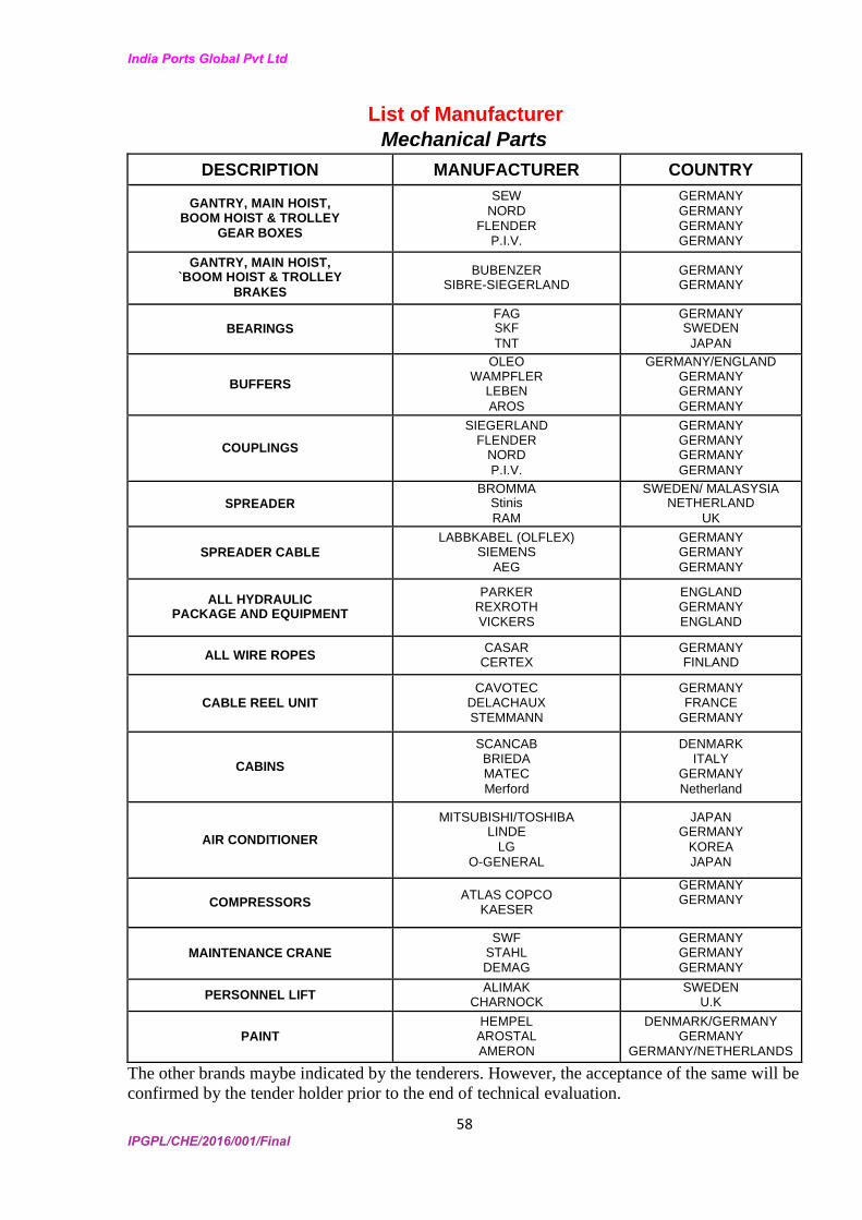
India Ports Global Pvt Ltd
58 IPGPL/CHE/2016/001/Final
List of Manufacturer Mechanical Parts
DESCRIPTION MANUFACTURER COUNTRY
GANTRY, MAIN HOIST, BOOM HOIST & TROLLEY
GEAR BOXES
SEW NORD
FLENDER P.I.V.
GERMANY GERMANY GERMANY GERMANY
GANTRY, MAIN HOIST, `BOOM HOIST & TROLLEY
BRAKES
BUBENZER SIBRE-SIEGERLAND
GERMANY GERMANY
BEARINGS FAG SKF TNT
GERMANY SWEDEN
JAPAN
BUFFERS
OLEO WAMPFLER
LEBEN AROS
GERMANY/ENGLAND GERMANY GERMANY GERMANY
COUPLINGS
SIEGERLAND FLENDER
NORD P.I.V.
GERMANY GERMANY GERMANY GERMANY
SPREADER BROMMA
Stinis RAM
SWEDEN/ MALASYSIA NETHERLAND
UK
SPREADER CABLE LABBKABEL (OLFLEX)
SIEMENS AEG
GERMANY GERMANY GERMANY
ALL HYDRAULIC PACKAGE AND EQUIPMENT
PARKER REXROTH VICKERS
ENGLAND GERMANY ENGLAND
ALL WIRE ROPES CASAR CERTEX
GERMANY FINLAND
CABLE REEL UNIT CAVOTEC
DELACHAUX STEMMANN
GERMANY FRANCE
GERMANY
CABINS
SCANCAB BRIEDA MATEC Merford
DENMARK ITALY
GERMANY Netherland
AIR CONDITIONER
MITSUBISHI/TOSHIBA LINDE
LG O-GENERAL
JAPAN GERMANY
KOREA JAPAN
COMPRESSORS ATLAS COPCO KAESER
GERMANY GERMANY
MAINTENANCE CRANE SWF
STAHL DEMAG
GERMANY GERMANY GERMANY
PERSONNEL LIFT ALIMAK CHARNOCK
SWEDEN U.K
PAINT HEMPEL AROSTAL AMERON
DENMARK/GERMANY GERMANY
GERMANY/NETHERLANDS
The other brands maybe indicated by the tenderers. However, the acceptance of the same will be
confirmed by the tender holder prior to the end of technical evaluation.
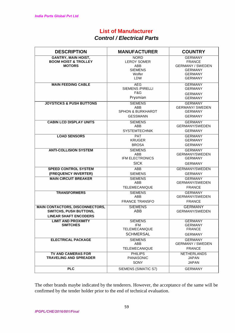
India Ports Global Pvt Ltd
59 IPGPL/CHE/2016/001/Final
List of Manufacturer Control / Electrical Parts
DESCRIPTION MANUFACTURER COUNTRY
GANTRY, MAIN HOIST, NORD GERMANY BOOM HOIST & TROLLEY LEROY SOMER FRANCE
MOTORS ABB GERMANY / SWEDEN SIEMENS GERMANY
Wolfer LDW
GERMANY GERMANY
MAIN FEEDING CABLE AEG GERMANY SIEMENS /PIRELLI GERMANY
F&G
Prysmian GERMANY GERMANY
JOYSTICKS & PUSH BUTTONS SIEMENS GERMANY ABB GERMANY/ SWEDEN SPHON & BURKHARDT GERMANY GESSMANN GERMANY
CABIN LCD DISPLAY UNITS SIEMENS GERMANY ABB GERMANY/SWEDEN SYSTEMTECHNIK GERMANY
LOAD SENSORS PAT GERMANY KRUGER GERMANY BROSA GERMANY
ANTI-COLLISION SYSTEM SIEMENS GERMANY ABB GERMANY/SWEDEN IFM ELECTRONICS GERMANY SICK GERMANY
SPEED CONTROL SYSTEM ABB GERMANY/SWEDEN (FREQUENCY INVERTER) SIEMENS GERMANY
MAIN CIRCUIT BREAKER SIEMENS GERMANY ABB GERMANY/SWEDEN TELEMECANIQUE FRANCE
TRANSFORMERS SIEMENS GERMANY ABB GERMANY/SWEDEN FRANCE TRANSFO FRANCE
MAIN CONTACTORS, DISCONNECTORS, SIEMENS GERMANY SWITCHS, PUSH BUTTONS, ABB GERMANY/SWEDEN LINEAR SHAFT ENCODERS
LIMIT AND PROXIMITY SIEMENS GERMANY SWITCHES IFM GERMANY
TELEMECANIQUE FRANCE SCHMERSAL GERMANY
ELECTRICAL PACKAGE SIEMENS GERMANY ABB GERMANY / SWEDEN TELEMECANIQUE FRANCE
TV AND CAMERAS FOR PHILIPS NETHERLANDS TRAVELING AND SPREADER PANASONIC JAPAN
SONY JAPAN
PLC SIEMENS (SIMATIC S7) GERMANY
The other brands maybe indicated by the tenderers. However, the acceptance of the same will be
confirmed by the tender holder prior to the end of technical evaluation.