Embed Size (px)
Citation preview
Strojarstvo 51 (3) 227-238 (2009) A. BUKŠA et. al., Ship Machinery Maintenance Concept... 227Ship Machinery Maintenance Concept... 227 227
CODEN STJSAO ISSN 0562-1887 ZX470/1383 UDK 629.5.054.03:629.5.083.4:657.471.14
Subject reviewThe first part of the paper presents a survey of approaches to maintenance over the last thirty years. A structure of maintenance costs and maintenance concept adjustment and design (MA-CAD) of ship machinery (propulsion engine) is presented here, which provides the required safety level and lowest costs in a life cycle. Improvement and extension of the MA-CAD method can be achieved by analysis of the most common important parts of the propulsion engine that fail, mostly in operation, by designing maintenance intervals and planning spare parts quantity. A diesel-engine propulsion system with gearbox has been chosen for the research. The data on failure and maintenance activities at propulsion engine breakdown in a seaway within a period of thirteen years have been obtained from the engine′s log book. The critical parts that fail mostly in operation are defined by an analysis of breakdowns (registered failure cycles). The critical components include the exhaust valve, injection valve and fuel pump. The most vulnerable part of the propulsion engine is the exhaust valve with the highest failure rate. By application of the method mentioned we obtain a model for the maintenance concept adjustment and design. The suggested model consists of two parts (a new MA-CAD): the ship and office. The engine machinery behaviour is monitored aboard the ship (failures and maintenance functioning) and the data are sent to the office. On the basis of the data, the office performs the analysis and adjusts (the models) maintenance concept.
Podešavanje i oblikovanje koncepta održavanja brodskog pogona
Pregledni članakU prvom dijelu rada predočen je pregled pristupa održavanja brodskog pogona u posljednjih trideset godina. Prikazana je struktura troškova održavanja, moguća rješenja redukcije troškova, kao i metoda za podešavanje i oblikovanje koncepta održavanja (MA–CAD) brodskog pogona (porivnog stroja), što omogućuje traženu razinu sigurnosti i najniže troškove u životnom ciklusu. Poboljšanje i proširenje MA-CAD metode može se postići: analizom kvarova porivnog stroja značajnih (kritičnih) komponenata koje najviše odlaze u eksploataciji, modeliranjem intervala održavanja i planiranjem količina pričuvnih dijelova. Za istraživanje odabran je dizel-motorni porivni sustav s reduktorom. Iz dnevnika stroja korišteni su podaci o kvarovima i akciji održavanja kod prekida operacije porivnog stroja za vrijeme plovidbe u vremenskom razdoblju od trinaest godina. Analizom zastoja (evidentiranih ciklusa kvarova) definiraju se kritične komponente koje najviše nastaju u eksploataciji. Tu spadaju ispušni ventil, rasprskač i pumpa goriva. Najugroženija komponenta porivnog sustava (porivnog stroja) je ispušni ventil s najvećom stopom kvara. Primjenom spomenute metode dolazi se do modela za podešavanje (modeliranje) koncepta održavanja. Predloženi model sastoji se od dva dijela (novi MA-CAD): brod i ured. Na brodu se snima ponašanje pogona (podaci o kvarovima i funkcioniranju održavanja) i šalje u ured. Ured na osnovi baze podataka analizira i podešava (modelira) koncept održavanja.
Ante BUKŠA, Ivica ŠEGULJA and Vinko TOMAS
Pomorski fakultet u Rijeci (Faculty of Maritime Studies in Rijeka),Studenska 2, HR - 51000 Rijeka Republic of Croatia
KeywordsConcept of maintenance Costs Diesel-engine propulsion system Maintenance Ship machinery
Ključne riječiBrodski pogon Dizel-motorni porivni sustav Koncept održavanja Održavanje Troškovi
Received (primljeno): 2008-07-10 Accepted (prihvaćeno): 2009-04-23
Ship Machinery Maintenance Concept Adjustment and Design
228 A. BUKŠA et. al., Ship Machinery Maintenance Concept... Strojarstvo 51 (3) 227-238 (2009)
Symbols/Oznake
p - predictability
- predvidljivost
t0 - guarantee time, h - vrijeme garancije, pomak ili parametar ulaza
tk - outage, h - dužina zastoja
β - shape parameter - parametar oblika
η - scale parameter, h
- parametar omjera
λ - failure rate, h-1 - stope kvara
CM - Corrective Maintenance or On-Failure Maintenance
- funkcija kumulativne raspodjele F(t)
CFR - Constant Failure Rate
- konstantna stopa kvara
DFR - Decreasing Failure Rate
- smanjujuća stopa kvara
ChF - Cumulative Hazard Function
- kumulativna funkcija intenziteta kvarova H(t)
ELFF - Expected Life Failure Frequency
- očekivana frekvencija kvara u vijeku
LCC - Life Cycle Costs
- troškovi životnog ciklusa
FM/CC - Failure Mode/Cause Combinations
- kombinacija moda kvara / uzrok
hF - Hazard Function
- funkcija intenziteta kvarova h(t)
IFR - Increasing Failure Rate - povećavajuća stopa kvara
ME - Main Engine - porivni stroj
MTBF - Mean Time Between Failures
- srednje vrijeme između kvarova
MTTF - Mean Time to Failure
- srednje vrijeme do kvara
SI - Significance Index
- indeks značaja
SP - Spare Parts
- pričuvni dijelovi
PDF - Probability Density Function
- funkcija gustoće vjerojatnosti f(t)
PM - Preventive Maintenance
- preventivno održavanje
RF - Reliability Function
- funkcija pouzdanosti R(t)
RI - Risk Index
- indeks rizika
TBF - Time Between Failure
- vrijeme između kvarova
TID - Type Item Installed
- tip instalirane komponente
1. Introduction
In technical literature a great number of papers in the field of technical system maintenance discuss general principles and maintenance approaches. In the 1970s it was debated whether it was better to perform preventive or corrective maintenance, as maintenance costs were expressed in operation costs. Planned surveys and maintenance were without any system. During those years, in most cases, maintenance was left to the goodwill of the crew, with no defined plans, which resulted in damage which could have been prevented in planned maintenance. Development of a maintenance plan proved to be indispensable, in order to enable the crew to perform all urgent maintenance activities within a defined period of time [1-2]. Planned maintenance and increased reliability have been used in air traffic for a long time, while in traditional mechanical engineering, including ship engineering, they were scarcely used in the 1970s. A study performed on ship diesel-engines
proved that planned maintenance results in increased reliability [3]. Fuel costs, as well as propulsion engine maintenance represent significant in a ship´s operation. There has always been a demand for the crew to perform certain routine maintenance activities. For such activities aboard the ship, there is always a shortage of time, particularly aboard ships that stay in port for a short period (containers, tankers). The Italian company SPA Grandi Motori Trieste offere their customers a maintenance contract [5]. Lloyd′s Register formed a group to find methods related to the establishment of diesel-engine conditions in 1964. [6]. In the 1980s a model of on-condition preventive maintenance was in use. This model was designed based on measurement and monitoring a series of influential parameters during operation, with the help of technical diagnostics on the basis of which the condition of equipment and decision were for necessary maintenance activities. The diesel-engine condition was determined by means of oil analysis [7], oil fog [8], using tribo-technologies [9], monitoring the machinery
Strojarstvo 51 (3) 227-238 (2009) A. BUKŠA et. al., Ship Machinery Maintenance Concept... 229Ship Machinery Maintenance Concept... 229 229
conditions by means of vibrations (Marine Management Centre – MMC – the branch office BP Shipping developed their own computer system CM, which uses machinery vibrations to determine its condition) [10-11]. Expert systems for maintenance were developed in the 1980s by the introduction of electronic computers [12-13]. MAN B&W developed a system with four software-programmed computer monitored surveillance of engine performance CoCoS (Computer Controlled Surveillance). CoCoS EDS (The Engine Diagnostics System) comprise recording, monitoring and diagnostics [14]. SULZER developed a system for ships machinery condition diagnostics named MAPEX (Monitoring and Maintenance Performance Enhancement with Expert Knowledge) [15].
The most reliable basis for determining a maintenance model is to monitor the proper equipment in operation, record failure cycles, their causes and conditions in which they occur. Research results of breakdowns show that most failures happen on the propulsion system [16–18]. Identified components, as part of the machinery system, are the most intensely maintained components aboard ships. They are the exhaust valve, the injection valve and fuel oil pump. The most vulnerable component of the propulsion engine is the exhaust valve with the highest failure rate.
Manufacturers of ship propulsion engine recommend planned maintenance activities based on propulsion engine working hours. A maintenance time concept, which is generally applied aboard ships, is not the most efficient maintenance method. Suggested manufacturers′ intervals can be modified for a number of factors that affect the condition and component′s performance. After analysis of operational data, a change in maintenance approach can result.
2. Maintenance costs structure
When considering maintenance of technical systems, a series of activities is implied that are needed to prevent conditions in breakdown, i. e., a return to the system from breakdown into an operational condition. However, the life cycle of a technical system begins its design. From that moment until it is scrapped (Phase-Out) certain measures are undertaken in order to achieve expected readiness of the system. Due to high maintenance costs in Great Britain in 1970, the researchers began to use the terrotechnology concept with the goal to optimize cycle maintenance costs [19-20].
The ship maintenance costs as part of ship operational costs for Nedlloyd company is shown in Table 1 [17].
Table 1. Maintenance costs Tablica 1. Troškovi održavanja
Costs / Troškovi PM CMPersonnel / Osoblje 81 % 19 %Third parties / Treće stranke 86 % 14 %Material / Materijal 78 % 22 %Average value / Prosječna vrijednost ≈ 82 % ≈ 18 %
The Table shows the ratio of preventive maintenance costs to corrective maintenance costs aboard Nedlloyd ships. Obviously, too much preventive maintenance was done (82 %). The conclusion is that preventive maintenance costs are too high in the total costs.
A maintenance concept is a combination of a preventive and corrective approach. The maintenance programme used aboard Nedlloyd ships, as well as by other companies, shows that it can be improved. Indicators for this conclusion are high maintenance labour costs and low material costs.
A great number of the crew engaged in maintenance, a high ratio of personnel costs in the total costs, a high PM/CM ratio and low material costs lead to two possible solutions for cost reduction:
To organize the crew to remove failure more • efficiently, and To design a maintenance concept so that preventive • and corrective maintenance are better balanced.
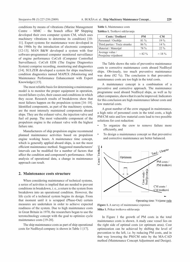
Figure 1. A survey of maintenance expensesSlika 1. Prikaz troškova održavanja
In Figure 1 the growth of PM costs in the total maintenance costs is shown. A study case vessel lies on the right side of optimal costs (or optimum area). Cost optimization can be achieved by shifting the level of prevention to the left, i.e. by reducing PM costs, and in that way lowering the PM/CM ratio by the MA-CAD method (Maintenance Concept Adjustment and Design).
230 A. BUKŠA et. al., Ship Machinery Maintenance Concept... Strojarstvo 51 (3) 227-238 (2009)
The method is used for adjustment and maintenance concept design by analysis of machinery failures and maintenance activities. The method reduces the LCC and at the same time satisfies safety limits.
3. Method for adjustment and design maintenance concept
The method is primarily based on historical data. However, these data are not always available, especially for new building projects. In this case, behaviour has
to be predicted from experience with previous, similar machinery. To design an initial maintenance concept for new equipment, predictions of expected behaviour are used on the basis of historical records, while adjustment of the maintenance concept is based on the records of actual behaviour of the equipment in operation. The initial maintenance concept design, as well as adjustment, uses a similar data analysis. The only difference is the origin of data (predicted or operational data).
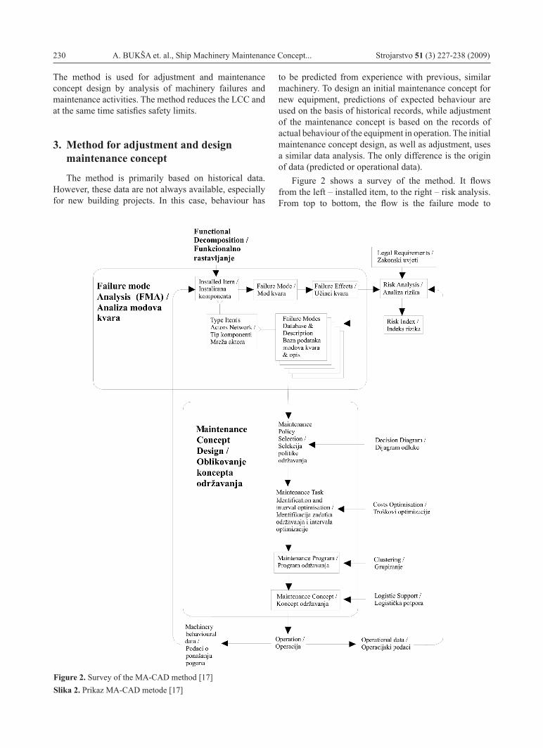
Figure 2 shows a survey of the method. It flows from the left – installed item, to the right – risk analysis. From top to bottom, the flow is the failure mode to
Figure 2. Survey of the MA-CAD method [17]Slika 2. Prikaz MA-CAD metode [17]

Strojarstvo 51 (3) 227-238 (2009) A. BUKŠA et. al., Ship Machinery Maintenance Concept... 231Ship Machinery Maintenance Concept... 231 231
the maintenance concept. Equipment identification is performed into systems and further on to the level of installed components, which are classified according to the component type.
Besides this, the risk related to possible failures should be identified. The risk is used to choose an efficient maintenance policy. The policy is improved with a maintenance goal that minimizes operational costs and keeps safety risk within acceptable limits.
Failure modes have consequences which are called failure effects. The failure effects critical state is classified by significance class and quantified by index risk.
Machinery behaviour and index risk for a defined failure mode are used to choose a particular maintenance policy.
Tasks identification implies considering: the critical failure effect state, failure occurrence probability and task efficiency. The goal is to reduce the risk by reducing failure occurrence probability, which is obtained by maintenance application.
Maintenance tasks are grouped in intervals into the maintenance programme. Specification logistic support for maintenance programme is the last step in the maintenance design.
4. Possible improvement and expansion of the MA-CAD methodThe improvement and expansion of the MA-CAD
method can be achieved by:1. An analysis of the failures of significant (critical)
components of the propulsion engine which fail mostly in the operational breakdown. In analysis, the operator’s suggestions, the ship’s age, type of propulsion engine (4-stroke or 2-stroke), conditions of the ship’s maintenance, skill and education of the crew, as well as differences in operational and environmental conditions are taken into consideration. It is necessary to monitor the component throughout its entire life cycle (precise monitoring in accordance with its identification number)
2. The life maintenance design. In research, Weibull distribution W(t0, η, β) is used. In the case of old machinery, where it is difficult to define the component's guarantee time t0, 2-parameter Weibull distribution is used. For the new machinery 3-parameter Weibull distribution is used. (The MA-CAD uses 3-parameter Weibull distribution).
3. The analysis of reliability of critical components through basic properties of the Weibull distribution (PDF, CDF, RF, HF and CHF [21]). Minimal reliability of the installed component will be obtained during the interval of maintenance, i. e., the maximal noncorrectness of the installed component.
4. Planning the quantity of spare parts. Table 2 shows characteristics of well-known methods for the maintenance concept design applied in the MA-CAD [17]. From the above presented results, the MA-CAD method has not involved the system of planning spare parts, which is very important in the maintenance concept design, and provides the basis for further costs reduction. Planning of spare parts quantity means extension of the method mentioned.
Table 2. Characteristics of method for maintenance concept design used in MA-CAD Tablica 2. Značajke metoda za dizajniranje koncepta održavanja korištenih u MA-CAD-u
Method / Metoda MA-CAD
ILS/LSA ILS - Integrated Logistic support / Integralna logistička potporaLSA - Logistic Support Analysis / Analiza logističke podrške
LCC - Life Cycle Costs. Phase : conceptual design → detailed design → fabrication → trials → operation → phase-out. /Faze vijeka jednog broda su: konceptualni dizajn → detaljni dizajn → proizvodnja → ispitivanje → operacija → otpis.Type item – the type item classifies items from the functional decomposition according to function, and working principles. /Tip komponente – klasificira instalirane komponente iz funkcionalnog rastavljanja.Failure mode properties – is an attempt to standardize and to structure information about failure modes, used in maintenance concept design. /Svojstvo moda kvara (predvidljivost, vrijeme reakcije i dokaz) – to je pokušaj da se normizira i strukturira informacija o modovima kvara, koja se koristi u dizajnu koncepta održavanja.FMECA - Failure Mode, Effects and Criticality Analysis /Mod kvara, učinci i analiza kritičnosti
ILS/LSA, Kelly Use study / Studija upotrebe
RCM/MSG – 3RCM - Reliability Centered Maintenance / Održavanje usmjereno na pouzdanostMSG – 3 - Maintenance Steering Group – 3
Risk analysis – its goal is to classify and quantify a risk. /Analiza rizika – ima za cilj klasificirati i kvantificirati rizik.Risk index – takes into consideration the importance of the failure effect and its expectancy. / Indeks rizika – uzima u obzir značajka učinka kvara i njegovo očekivanje (RI = SI* ELFF).Significance analysis – classifies the failure effects on the system, the operator and the environment. /Analiza značajke - klasificira učinke efekata kvara na sustav, operatera i okolinu.
Kelly, Gits
Functional decomposition - the decomposition is extended into the type item decomposition. /Funkcionalno rastavljanje sustava - ono se proširuje rastavljanjem tipa komponente.
232 A. BUKŠA et. al., Ship Machinery Maintenance Concept... Strojarstvo 51 (3) 227-238 (2009)
5. Choice of ship propulsion system
A diesel-engine propulsion system with a gearbox has been chosen for the research. The propulsion system consists of the mean revolution diesel-engine MAN 7L 400/500 power ≈ 2200 kW (3000 HP), the gearbox and the shaft with propeller. The gearbox is a Renk type that reduces speed rotation of the propulsion engine of 430 min-1 to the speed rotation of the ship propeller from 185 min-1 (i = 430/185 ≅ 2,3). The research is based on the original data collected from the daily reports of the diesel-engine mentioned within a period of thirteen years [22]. The propulsion engine daily reports are recorded in the log book run daily from 00 to 24 hours at sea and in port.
6. Results of research of failure incidences
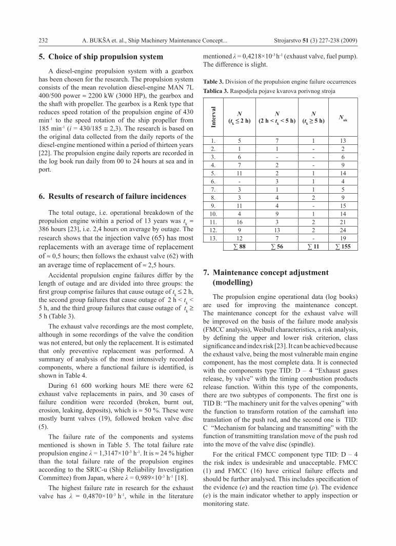
The total outage, i.e. operational breakdown of the propulsion engine within a period of 13 years was tk ≈ 386 hours [23], i.e. 2,4 hours on average by outage. The research shows that the injection valve (65) has most replacements with an average time of replacement of ≈ 0,5 hours; then follows the exhaust valve (62) with an average time of replacement of ≈ 2,5 hours.
Accidental propulsion engine failures differ by the length of outage and are divided into three groups: the first group comprise failures that cause outage of tk ≤ 2 h, the second group failures that cause outage of 2 h < tk < 5 h, and the third group failures that cause outage of tk ≥ 5 h (Table 3).
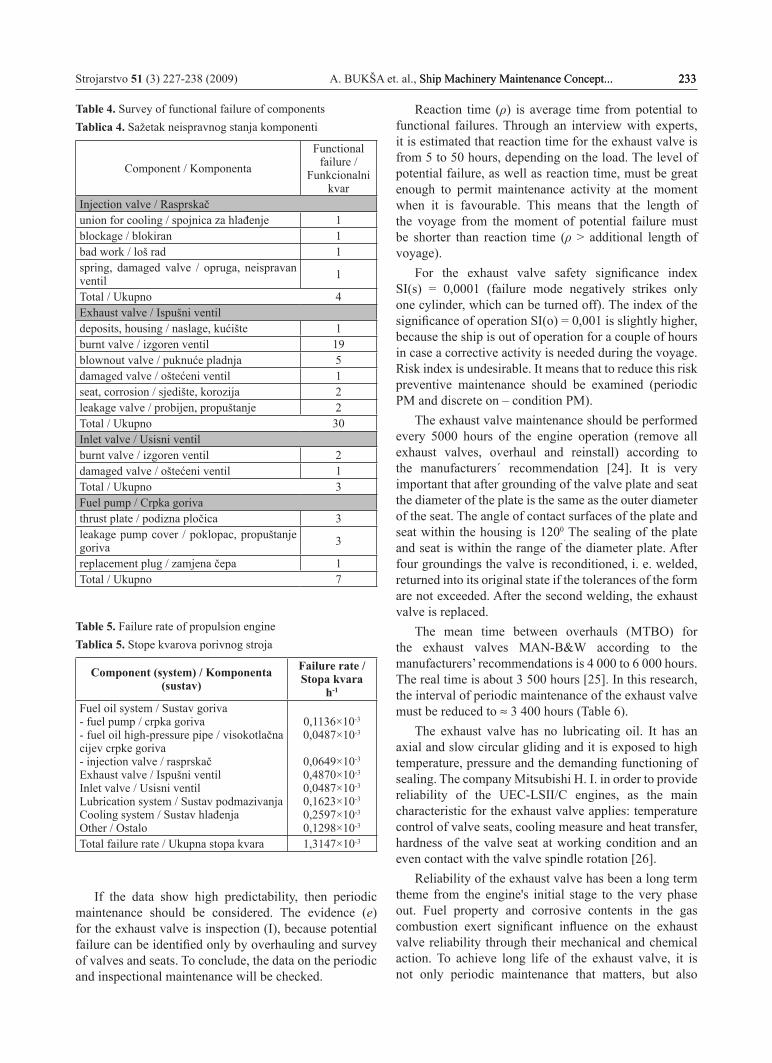
The exhaust valve recordings are the most complete, although in some recordings of the valve the condition was not entered, but only the replacement. It is estimated that only preventive replacement was performed. A summary of analysis of the most intensively recorded components, where a functional failure is identified, is shown in Table 4.
During 61 600 working hours ME there were 62 exhaust valve replacements in pairs, and 30 cases of failure condition were recorded (broken, burnt out, erosion, leaking, deposits), which is ≈ 50 %. These were mostly burnt valves (19), followed broken valve disc (5).
The failure rate of the components and systems mentioned is shown in Table 5. The total failure rate propulsion engine λ = 1,3147×10⁻³ h-1. It is ≈ 24 % higher than the total failure rate of the propulsion engines according to the SRIC-u (Ship Reliability Investigation Committee) from Japan, where λ = 0,989×10-3 h-1 [18].
The highest failure rate in research for the exhaust valve has λ = 0,4870×10⁻³ h-1, while in the literature
mentioned λ = 0,4218×10⁻³ h-1 (exhaust valve, fuel pump). The difference is slight.
Table 3. Division of the propulsion engine failure occurrencesTablica 3. Raspodjela pojave kvarova porivnog stroja
Inte
rval
N (tk ≤ 2 h)
N (2 h < tk < 5 h)
N (tk ≥ 5 h) Nuk
1. 5 7 1 132. 1 1 - 23. 6 - - 64. 7 2 - 95. 11 2 1 146. - 3 1 47. 3 1 1 58. 3 4 2 99. 11 4 - 1510. 4 9 1 1411. 16 3 2 2112. 9 13 2 2413. 12 7 - 19
∑ 88 ∑ 56 ∑ 11 ∑ 155
7. Maintenance concept adjustment (modelling)
The propulsion engine operational data (log books) are used for improving the maintenance concept. The maintenance concept for the exhaust valve will be improved on the basis of the failure mode analysis (FMCC analysis), Weibull characteristics, a risk analysis, by defining the upper and lower risk criterion, class significance and index risk [23]. It can be achieved because the exhaust valve, being the most vulnerable main engine component, has the most complete data. It is connected with the components type TID: D – 4 “Exhaust gases release, by valve” with the timing combustion products release function. Within this type of the components, there are two subtypes of components. The first one is TID B: “The machinery unit for the valves opening” with the function to transform rotation of the camshaft into translation of the push rod, and the second one is TID: C “Mechanism for balancing and transmitting” with the function of transmitting translation move of the push rod into the move of the valve disc (spindle).
For the critical FMCC component type TID: D – 4 the risk index is undesirable and unacceptable. FMCC (1) and FMCC (16) have critical failure effects and should be further analysed. This includes specification of the evidence (e) and the reaction time (ρ). The evidence (e) is the main indicator whether to apply inspection or monitoring state.
Strojarstvo 51 (3) 227-238 (2009) A. BUKŠA et. al., Ship Machinery Maintenance Concept... 233Ship Machinery Maintenance Concept... 233 233
Table 4. Survey of functional failure of componentsTablica 4. Sažetak neispravnog stanja komponenti
Component / Komponenta
Functional failure /
Funkcionalni kvar
Injection valve / Rasprskačunion for cooling / spojnica za hlađenje 1blockage / blokiran 1bad work / loš rad 1spring, damaged valve / opruga, neispravan ventil 1
Total / Ukupno 4Exhaust valve / Ispušni ventildeposits, housing / naslage, kućište 1burnt valve / izgoren ventil 19blownout valve / puknuće pladnja 5damaged valve / oštećeni ventil 1seat, corrosion / sjedište, korozija 2leakage valve / probijen, propuštanje 2Total / Ukupno 30Inlet valve / Usisni ventilburnt valve / izgoren ventil 2damaged valve / oštećeni ventil 1Total / Ukupno 3Fuel pump / Crpka gorivathrust plate / podizna pločica 3leakage pump cover / poklopac, propuštanje goriva 3
replacement plug / zamjena čepa 1Total / Ukupno 7
Table 5. Failure rate of propulsion engine Tablica 5. Stope kvarova porivnog stroja
Component (system) / Komponenta (sustav)
Failure rate / Stopa kvara
h-1
Fuel oil system / Sustav goriva- fuel pump / crpka goriva- fuel oil high-pressure pipe / visokotlačna cijev crpke goriva - injection valve / rasprskačExhaust valve / Ispušni ventilInlet valve / Usisni ventilLubrication system / Sustav podmazivanjaCooling system / Sustav hlađenjaOther / Ostalo
0,1136×10⁻³
0,0487×10⁻³
0,0649×10⁻³
0,4870×10⁻³
0,0487×10⁻³
0,1623×10⁻³
0,2597×10⁻³
0,1298×10⁻³
Total failure rate / Ukupna stopa kvara 1,3147×10⁻³
If the data show high predictability, then periodic maintenance should be considered. The evidence (e) for the exhaust valve is inspection (I), because potential failure can be identified only by overhauling and survey of valves and seats. To conclude, the data on the periodic and inspectional maintenance will be checked.
Reaction time (ρ) is average time from potential to functional failures. Through an interview with experts, it is estimated that reaction time for the exhaust valve is from 5 to 50 hours, depending on the load. The level of potential failure, as well as reaction time, must be great enough to permit maintenance activity at the moment when it is favourable. This means that the length of the voyage from the moment of potential failure must be shorter than reaction time (ρ > additional length of voyage).
For the exhaust valve safety significance index SI(s) = 0,0001 (failure mode negatively strikes only one cylinder, which can be turned off). The index of the significance of operation SI(o) = 0,001 is slightly higher, because the ship is out of operation for a couple of hours in case a corrective activity is needed during the voyage. Risk index is undesirable. It means that to reduce this risk preventive maintenance should be examined (periodic PM and discrete on – condition PM).
The exhaust valve maintenance should be performed every 5000 hours of the engine operation (remove all exhaust valves, overhaul and reinstall) according to the manufacturers΄ recommendation [24]. It is very important that after grounding of the valve plate and seat the diameter of the plate is the same as the outer diameter of the seat. The angle of contact surfaces of the plate and seat within the housing is 1200
. The sealing of the plate and seat is within the range of the diameter plate. After four groundings the valve is reconditioned, i. e. welded, returned into its original state if the tolerances of the form are not exceeded. After the second welding, the exhaust valve is replaced.
The mean time between overhauls (MTBO) for the exhaust valves MAN-B&W according to the manufacturers’ recommendations is 4 000 to 6 000 hours. The real time is about 3 500 hours [25]. In this research, the interval of periodic maintenance of the exhaust valve must be reduced to ≈ 3 400 hours (Table 6).
The exhaust valve has no lubricating oil. It has an axial and slow circular gliding and it is exposed to high temperature, pressure and the demanding functioning of sealing. The company Mitsubishi H. I. in order to provide reliability of the UEC-LSII/C engines, as the main characteristic for the exhaust valve applies: temperature control of valve seats, cooling measure and heat transfer, hardness of the valve seat at working condition and an even contact with the valve spindle rotation [26].
Reliability of the exhaust valve has been a long term theme from the engine's initial stage to the very phase out. Fuel property and corrosive contents in the gas combustion exert significant influence on the exhaust valve reliability through their mechanical and chemical action. To achieve long life of the exhaust valve, it is not only periodic maintenance that matters, but also

234 A. BUKŠA et. al., Ship Machinery Maintenance Concept... Strojarstvo 51 (3) 227-238 (2009)
maintenance of the injection valve as the key factor for the exhaust valve.
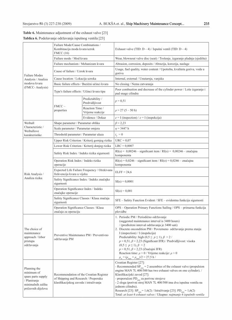
The research results obtained from the given parameters for the maintenance concept adjustment (modelling) of the exhaust valve are shown in Table 6.
The burnt valve disc (seat) is the most frequent failure mode of the exhaust valve (TID: A – 1 “Valve and Seat”).
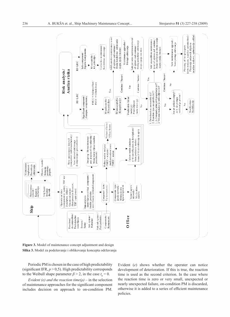
On the basis of analysis and examples of the exhaust valve, a model is designed for the maintenance concept adjustment and design and is shown in Figure 3.
The model for maintenance concept adjustment and design (new MA-CAD) consists of two parts:
1. The ship – the machinery behaviour is monitored, a data base is formed and sent to the office. Daily reports on the machinery are recorded in a log book during 24 hours. Data on failures and maintenance activities are entered, as well as duration of breakdown.
2. The office – uses the database, performs a data analysis and adjusts (models) the maintenance concept. The procedure includes the following steps:
Operational data → analysis data (significant component) → identifying the type of component → actors network → FMCC – analysis → designing life maintenance and analysis of reliability → risk analysis → maintenance task identification and interval optimization → task clustering → maintenance levels and resources allocation → the planning of spare parts → Maintenance concept.
2.1. Operational data – contains the components data (system) per cylinder, the propulsion engine working hours, the time between failures (TBF), condition and failure description.
2.2. Data analysis – critical (significant) components are defined. Within a critical component in the failure mode analysis significant FMCC-s are identified, i.e. significant failure effects.
2.3. Identifying component type – is achieved by functional decomposition of the system. Ship function is divided into sub-functions. Realization of sub-functions is sustaiwed with supporting systems, which are later decomposed until the lever of the installed components is reached. Type components are identified for the installed components. Decomposition is preceded into sub-type components and basic type components.
2.4. Actor´s network – is a graphic presentation of component type functionality. The actor’s network is designed to show the expansion of the failure effect in the case of complex components that include a number of sub-functions.
2.5. FMCC – analysis – includes the component type specification, the sub-type and the component itself.
Functional failure is identified at the lowest level of the functional decomposition. Basic failure effects are defined and component type failure effects.
2.6. Designing life maintenance and analysis of reliability – for the given samples, except for Weibull parameters β and η, a mean time between failures (MTBF) will be defined, by standard deviations σ and the property of failure mode prediction p. The scale parameter η represents characteristic life (maintenance interval).
2.7. Risk analysis – includes definition of the upper and lower risk criterion, significance analysis and risk index of the critical FMCC-s. If RI > LRC the component is significant; namely, if RI < LRC the component is non-significant and has an acceptable risk index. Non-significant components are allocated corrective maintenance.
A significant component has a significant failure effect, which that is why its risk index can be undesirable and unacceptable. For each significant component which is identified in the risk analysis, an efficient maintenance policy is chosen.
Preventive maintenance activity tends to maintain operational condition (a failure has not yet happened), while corrective maintenance activity should return the component into operational condition. When preventive maintenance is prescribed, the desired effect is to lower the ELFF and the risk index at the same time. In other words, failure effects are always the same, but maintenance helps to reduce the probability of their occurrence.
RI undesirable – when the risk index in an undesirable area, CM is added as a possibility for efficient maintenance policy. Later, during costs optimization, it will be decided whether CM can be accepted (if CM costs are lower than PM costs?).
RI unacceptable – the risk index lies in an unacceptable area, therefore PM is not suitable. The risk index can be lowered to acceptable levels by performing maintenance or modification, which is only a way to lower the significance index, so the risk index is lowered.
Failure predictability determines selection of the periodic approach. Predictability shows whether the failure behaviour can be checked by means of periodic activities. Particularly, it shows whether the failure rate is in decrease or constant (DFR, CFR) or increasing (IFR). If the failure rate is dropping or constant (DFR, CFR), predictability is zero (p = 0, β ≤ 1 and t0 = 0). Periodic maintenance is inefficient in such cases; therefore, it will not be added to a series of efficient maintenance policies.
Preventive maintenance can be considered if predictability is low (0 < p ≤ 0,5, 1 < β < 2 and t0 = 0). However, on – condition PM is more suitable.
Strojarstvo 51 (3) 227-238 (2009) A. BUKŠA et. al., Ship Machinery Maintenance Concept... 235Ship Machinery Maintenance Concept... 235 235
Table 6. Maintenance adjustment of the exhaust valve [23]Tablica 6. Podešavanje održavanja ispušnog ventila [23]
Failure Modes Analysis / Analiza modova kvara(FMCC- Analysis)
Failure Mode/Cause Combinations / Kombinacija moda kvara/uzrok FMCC (16)
Exhaust valve (TID: D – 4) / Ispušni ventil (TID: D – 4)
Failure mode / Mod kvara Wear, blownout valve disc (seat) / Trošenje, izgaranje pladnja (sjedišta)
Failure mechanism / Mehanizam kvara Abrasion, corrosion, deposits / Abrazija, korozija, naslage
Cause of failure / Uzrok kvara Usage, fuel quality, water content / Upotreba, kvaliteta goriva, voda u gorivu
Cause location / Lokacija uzroka Internal, external / Unutarnja, vanjska
Basic failure effects / Bazični učinci kvara No closing / Nema zatvaranja
Type′s failure effects / Učinci kvara tipa Poor combustion and decrease of the cylinder power / Loše izgaranje i pad snage cilindra
FMCC – properties
Predictability / Predvidljivost p = 0,51
Reaction Time / Vrijeme reakcije ρ ≈ 27 (5 – 50 h)
Evidence / Dokaz e = I (inspection) / e = I (inspekcija)
WeibullCharacteristic / Weibullovekarakteristike
Shape parameter / Parametar oblika β = 2,23
Scale parameter / Parametar omjera η = 3447 h
Threshold parameter / Parametar ulaza t0 = 0
Risk Analysis / Analiza rizika
Upper Risk Criterion / Kriterij gornjeg rizika URC = 0,07
Lower Risk Criterion / Kriterij donjeg rizika LRC = 0,0007
Safety Risk Index / Indeks rizika sigurnosti RI(s) = 0,00246 – significant item / RI(s) = 0,00246 – značajna komponenta
Operation Risk Index / Indeks rizika operacije
RI(o) = 0,0246 – significant item / RI(o) = 0,0246 – značajna komponenta
Expected Life Failure Frequency / Očekivana frekvencija kvara u vijeku ELFF = 24,6
Safety Significance Index / Indeks značajke sigurnosti SI(s) = 0,0001
Operation Significance Index / Indeks značajke operacije SI(o) = 0,001
Safety Significance Classes / Klasa značaja sigurnosti SFE – Safety Function Evident / SFE – evidentna funkcija sigurnosti
Operation Significance Classes / Klasa značaja za operaciju
OPS – Operation Primary Functions Sailing / OPS – primarna funkcija plovidbe
The choice of maintenance approach / Izbor pristupaodržavanja
Preventive Maintenance PM / Preventivno održavanje PM
1. Periodic PM / Periodično održavanje (suggested maintenance interval is 3400 hours) / (predloženi interval održavanja je 3400 sati)2. Discrete oncondition PM / Povremeno održavanje prema stanju I (inspection) / I (inspekcija) Predictability: high (0,5 ≤ p ≤ 1), β > 2 / p = 0,51, β = 2,23 (Significant IFR) / Predvidljivost: visoka (0,5 ≤ p ≤ 1), β > 2 p = 0,51, β = 2,23 (Značajni IFR) Reaction time: ρ > 0 / Vrijeme reakcije: ρ > 0 ρsr = (ρmax + ρmin)/2 = 27,5 h /
Planning the minimum of spare parts supply / Planiranje minimalnih zaliha pričuvnih dijelova
Recommendation of the Croatian Register of Shipping and Research / Preporuka klasifikacijskog zavoda i istraživanja
Croatian Register [27]: - Recommended SPmin = 2 assembies of the exhaust valve (propulsion engine MAN 7L 400/500 has two exhaust valves on one cylinder). /Klasifikacijski zavod [27]:- preporučeni PDmin za porivne strojeve- 2 sloga (porivni stroj MAN 7L 400/500 ima dva ispušna ventila na jednom cilindru).Research [23]: SPmin = 1,6(2) / Istraživanje [23]: PDmin = 1,6(2)Total: at least 6 exhaust valves / Ukupno: najmanje 6 ispušnih ventila
236 A. BUKŠA et. al., Ship Machinery Maintenance Concept... Strojarstvo 51 (3) 227-238 (2009)
Figure 3. Model of maintenance concept adjustment and designSlika 3. Model za podešavanje i oblikovanje koncepta održavanja
Periodic PM is chosen in the case of high predictability (significant IFR, p > 0,5). High predictability corresponds to the Weibull shape parameter β > 2, in the case t0 = 0.
Evident (e) and the reaction time(ρ) – in the selection of maintenance approaches for the significant component includes decision on approach to on-condition PM.
Evident (e) shows whether the operater can notice development of deterioration. If this is true, the reaction time is used as the second criterion. In the case where the reaction time is zero or very small, unexpected or nearly unexpected failure, on-condition PM is discarded, otherwise it is added to a series of efficient maintenance policies.
Strojarstvo 51 (3) 227-238 (2009) A. BUKŠA et. al., Ship Machinery Maintenance Concept... 237Ship Machinery Maintenance Concept... 237 237
The reaction time in relation to the inspection interval determines a potential failure before a functional failure occurs. It depends on the applied monitoring type, continuous or discrete. In the case of continual monitoring evident (e) is P (performance), S (sensory) and V (visual), and the component′s condition is continually known. The periodic interval can come close to the MTTF (expected time to the failure). In the case of discrete on-condition PM tasks, the evident (e) is V (visual), I (inspection), T (tools) and H (hidden). With discrete on-condition PM tasks, it is assumed that potential failure can be noticed during inspection time and the reaction time ρ > 0.
2.8. Maintenance task identification and interval optimization – follows after the selection of maintenance politics, and comprises a specification of the maintenance task contents and the optimization interval. Cost optimization is included in maintenance concept adjustment. They are costs corrective and preventive maintenance. The lowest maintenance cost is requested for each FMCC.
2.9. Task clustering – is used when maintenance task for a definite component is specified. Task can be clustered on two levels: component and system.
2.10. Maintenance levels and resources allocation – the maintenance program has been completed and each task is allocated a level of execution. Four levels are identified: the ship (this is done by the crew during operation), the port (the item reconditioned by the crew, during stay in port), shore (third parties are included in such maintenance) and the dock (these are PM task). Required spare parts, tools and facilities are identified.
2.11. Planning spare parts – is important with maintenance concept adjustment and design, and gives a basis for further costs reduction. The required number of spare parts will be obtained if the average rate of usage λu is divided by the mean time between failures MTBF. The recommended minimal spare parts supplies for maintaining the ship safety levels are added to that number.
2.12. Maintenance concept – planning spare parts is the last step in maintenance concept design. The following stage is to deploy it aboard the sailing ship.
The operational maintenance concept should be reviewed from time to time and adapted if operational data differ grealty from the original estimated data used for maintenance concept design. After some time the company policy can be revised by defining new significance and risk criteria.
8. Conclusion
The manufacturers of the ship propulsion engines give their recommendations on planned maintenance activities, which are determined by the working hours of the propulsion engine. Maintenance concept on time, which is generally used aboard ships, does not represent the most efficient maintenance method, therefore the manufacturers; suggested intervals can be modified due to a series of factors that influence the component’s condition and performance approach. For research from the engine log book data are used on failures and maintenance activities at the breakdown of the propulsion engine operation at sea.
The method for maintenance concept design and adjustment (MA-CAD) is used in the research. The MA-CAD method begins from an installed component to the risk analysis, i.e. from the failure mode to maintenance concept. The method minimizes LCC and satisfies safety limits. For initial maintenance concept design, predictions of expected behaviour for the new equipment are used, while the maintenance concept adjustment is based on monitoring the actual behaviour of the equipment in use. The maintenance concept design of significant components based on real operational data is more reliable than the initial maintenance concept for a new ship.
The model obtained for maintenance concept adjustment and design (new MA-CAD) consists of two parts: the ship and office. Aboard the ship, machinery behaviour is monitored (data on failures and maintenance functioning) and sent to the office. In the office, an analysis and maintenance concept adjustment (modelling) is performed on the basis of the database, following these steps:
an analysis of data through distribution of incidence • of propulsion engine failures, failure rate and critical components analysisfunctional decomposition on the basis of function • and component identifying the component typethe actor´s network graphic presentation of the type • component functionalitythe life maintenance designing• and reliability analysis applying the Weibull distribution lawa risk analysis defining the upper and lower criterion • risk, the significance class and risk index, andspare parts supplies planning.•
The model can be used in shipping companies for maintenance concept adjustment for a given type of propulsion machinery. The suggested model can be used in shipyards for the initial maintenance concept design for newly-built ships and propulsion machinery of the same type.
238 A. BUKŠA et. al., Ship Machinery Maintenance Concept... Strojarstvo 51 (3) 227-238 (2009)
REFERENCES
1. ...: Considerations on systematic or preventive maintenance, The Motor Ship,53 (1972), 622, 57a – 58.
2. SCHAPAL, P.: Vorbeugende Instandkaltung von Schiffsmaschinenanlagen, Hansa, 111 (1974), 4, 485 – 488.
3. BLAESER, H.; WEERTZ, K.: Improving the reliability of diesel engines, Shipping World & Shipbuilder, 165 (1972), 3870, 1375 – 1377.
4. ...: Medium speed engines – Maintenance for reliability, Marine Propulsion Internat., July/August, (1989), 18.
5. ...: Maintenance under engine builder′s contract, Marine Propulsion Int., March, (1981), 42.
6. ...: Diesel Engine Condition Monitoring Research, The Motor Ship, 68 (1987), 798, 20.
7. FUCKS, A.: Zustandsermittlung des Dieselmptors durch Olanalyse-ein Weg zur Einhaltung betriebsgerechter Standzeiten, Jahrbuch STG, 73 (1979), 27 – 29.
8. BEHRENS, H. P.: Triebraumüberwachung von Grobdieselmotoren durch Ölnebeldetektion, Hansa, 119 (1982), 18, II. September, 1209 – 1211.
9. ....: Repair cost reductions from “Tribo-Technology”, Marine Propulsion Intern., (1987), March, 13-14.
10. ...: Vibration monitoring to reduce maintenance costs, Marine Propulsion Intern., March, (1987), 9 – 10.
11. ...: Computerized condition monitoring optimizes maintenance, The Motor Ship, 69 (1988), 813, 62.
12. ...: Engine advances and expert systems, The Motor Ship, June, 1989.
13. DVORNIK, J.: Primjena ekspertnog sustava u rješavanju pogonskih smetnji brodskog motora, Naše more 49 (2002), 3-4, 117 – 125.
14. ...: “The Intelligent Engine: Development Status and Prospects”, MAN&W Diesel A/S, Copenhagen, Publ. No. P. 360 – 399.
15. PEDERSON S. P.: Development Towards the Intelligent Engine, 16th International Marine Propulsion Conference, London, 1994.
16. KRAPP, R.: Why is increased redundancy needed, The Motor Ship, The 18th Annual Marine Propulsion Conference, Hamburg, 21-22 March, (1996), 13 – 21.
17. VUČINIĆ, B.: MA – CAD, Maintenance Concept Adjustment and Design, Delft, Faculty of Mechanical Engineering and Marine Technology, 1994.
18. OZAKI, Y.: An introduction to the ABS Guide for Propulsion Redundancy, Guide for Propulsion Redundancy, The Motor Ship, June, (1997), 101 – 112.
19. ČALA, I.: Suvremeni pristup strategiji održavanja, Management i održavanje, 1 (1994).
20. TOMIĆ, M.; ADAMIĆ, Ž.: Pouzdanost u funkciji održavanja tehničkih sistema, Beograd, Tehnička knjiga, 1986.
21. CHI – CHAO L.: A Comparison Between the Weibull and Lognormal Used to Analyze Reliability Data, Department of Manufacturing engineering and Operations, University of Nottingham, 1997.
22. ...: Dnevnici stroja MAN 7L 400/500, Od 1982. – 1994. godine.
23. BUKŠA, A.: Modeliranje održavanja brodskog porivnog sustava, Doktorska disertacija, Pomorski fakultet u Rijeci, Rijeka 2005.
24. ...: Operating manual for diesel engines, Type 7L 400/500, Maschinenfabrik Augsburg-Nürberg Aktiengesellschaft D – 8900 Augsburg 1, Stadtbachstrasse 1, D 365617 E.
25. OBNER, H. O.: Identification of Failures And Damages In Modern 2-stroke Engines, Schiff & Hafen, 40 (1988), 7, 30 – 35.
26. MOTOMURA, O.: Reliability aspects and benefits in low aped marine diesel engines, The Motor Ship, The 18th Annual Marine Propulsion Conference, Hamburg, 21-22, March, (1996), 95 – 111.
27. ...: Pravila za tehnički nadzor pomorskih brodova, Dio 7. – strojni uređaj, Split, Hrvatski registar brodova, 2002.