Embed Size (px)
Citation preview

SHINSUNG ENG EFU SHINSUNG ENG EFU Specification / ManualSpecification / ManualSpecification / ManualSpecification / Manual
EFU SPECIFICATION
COMPANY SHINSUNG ENG
PERSON IN CHARGE SO, SOON KI / MANAGER
TEL +82-31-788-9024
FAX +82-31-788-9420
EMAIL [email protected]
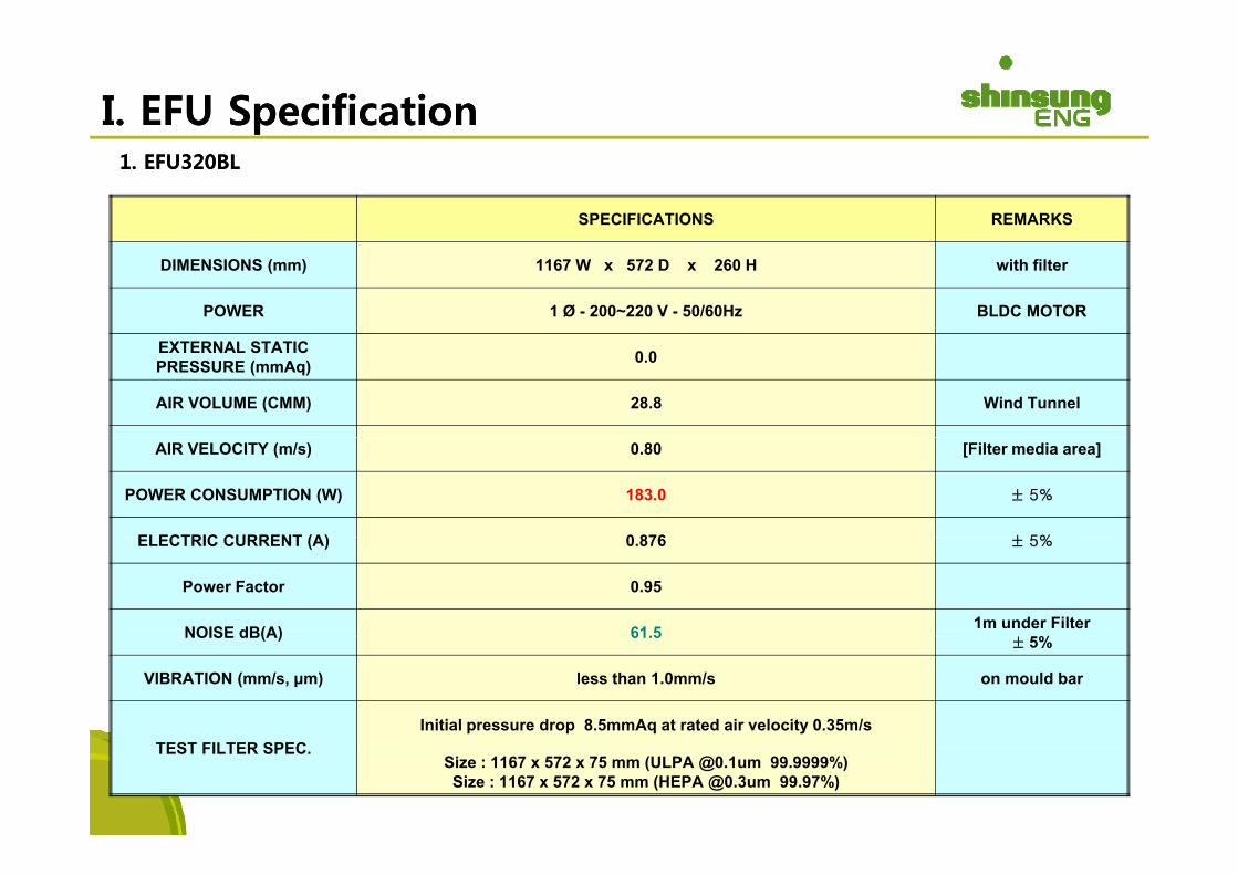
I. I. EFU EFU SpecificationSpecification1. EFU320BL1. EFU320BL
SPECIFICATIONS REMARKS
DIMENSIONS (mm) 1167 W x 572 D x 260 H with filter
POWER 1 Ø - 200~220 V - 50/60Hz BLDC MOTOR
EXTERNAL STATICPRESSURE (mmAq) 0.0
AIR VOLUME (CMM) 28.8 Wind Tunnel
AIR VELOCITY (m/s) 0.80 [Filter media area]
POWER CONSUMPTION (W) 183.0 ± 5%
ELECTRIC CURRENT (A) 0 876 ± 5%ELECTRIC CURRENT (A) 0.876 ± 5%
Power Factor 0.95
NOISE dB(A) 61.5 1m under Filter%NOISE dB(A) 61.5
± 5%
VIBRATION (mm/s, μm) less than 1.0mm/s on mould bar
Initial pressure drop 8.5mmAq at rated air velocity 0.35m/sTEST FILTER SPEC.
Size : 1167 x 572 x 75 mm (ULPA @0.1um 99.9999%)Size : 1167 x 572 x 75 mm (HEPA @0.3um 99.97%)

2. EFU321BL2. EFU321BL
SPECIFICATIONS REMARKS
DIMENSIONS (mm) 1167 W x 1167 D x 260 H with filter
POWER 1 Ø - 200~220 V - 50/60Hz BLDC MOTOR
EXTERNAL STATICPRESSURE (mmAq) 0.0
AIR VOLUME (CMM) 61.0 Wind Tunnel
AIR VELOCITY (m/s) 0.80 [Filter media area]
POWER CONSUMPTION (W) 356.0 ± 5%
ELECTRIC CURRENT (A) 1 703 ± 5%ELECTRIC CURRENT (A) 1.703 ± 5%
Power Factor 0.95
NOISE dB(A) 62.5 1m under Filter%NOISE dB(A) 62.5
± 5%
VIBRATION (mm/s, μm) less than 1.0mm/s on mould bar
Initial pressure drop 8.5mmAq at rated air velocity 0.35m/sTEST FILTER SPEC.
Size : 1167 x 1167 x 75 mm (ULPA @0.1um 99.9999%)Size : 1167 x 1167 x 75 mm (HEPA @0.3um 99.97%)
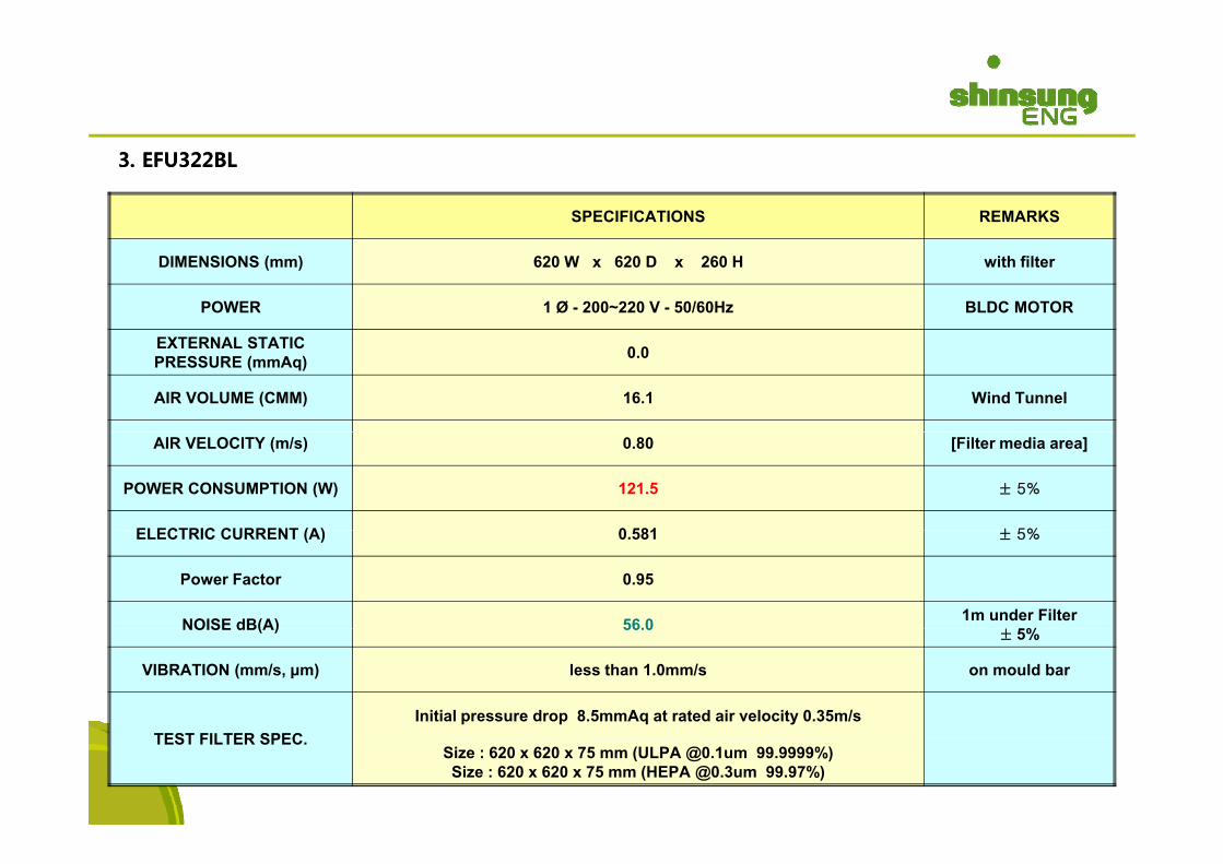
3. EFU322BL 3. EFU322BL
SPECIFICATIONS REMARKS
DIMENSIONS (mm) 620 W x 620 D x 260 H with filter
POWER 1 Ø - 200~220 V - 50/60Hz BLDC MOTOR
EXTERNAL STATICPRESSURE (mmAq) 0.0
AIR VOLUME (CMM) 16.1 Wind Tunnel
AIR VELOCITY (m/s) 0.80 [Filter media area]
POWER CONSUMPTION (W) 121.5 ± 5%
ELECTRIC CURRENT (A) 0 581 ± 5%ELECTRIC CURRENT (A) 0.581 ± 5%
Power Factor 0.95
NOISE dB(A) 56.0 1m under Filter%NOISE dB(A) 56.0
± 5%
VIBRATION (mm/s, μm) less than 1.0mm/s on mould bar
Initial pressure drop 8.5mmAq at rated air velocity 0.35m/sTEST FILTER SPEC.
Size : 620 x 620 x 75 mm (ULPA @0.1um 99.9999%)Size : 620 x 620 x 75 mm (HEPA @0.3um 99.97%)

4. EFU325BL4. EFU325BL
SPECIFICATIONS REMARKS
DIMENSIONS (mm) 1500 W x 1000 D x 260 H with filter
POWER 1 Ø - 200~220 V - 50/60Hz BLDC MOTOR
EXTERNAL STATICPRESSURE (mmAq) 0.0
AIR VOLUME (CMM) 67.3 Wind Tunnel
AIR VELOCITY (m/s) 0.80 [Filter media area]
POWER CONSUMPTION (W) 401.0 ± 5%
ELECTRIC CURRENT (A) 1 919 ± 5%ELECTRIC CURRENT (A) 1.919 ± 5%
Power Factor 0.95
NOISE dB(A) 64.0 1m under Filter%NOISE dB(A) 64.0
± 5%
VIBRATION (mm/s, μm) less than 1.0mm/s on mould bar
Initial pressure drop 8.5mmAq at rated air velocity 0.35m/sTEST FILTER SPEC.
Size : 1500 x 1000 x 75 mm (ULPA @0.1um 99.9999%)Size : 1500 x 1000 x 75 mm (HEPA @0.3um 99.97%)

5. EFU400BL 5. EFU400BL
SPECIFICATIONS REMARKS
DIMENSIONS (mm) 1000 W x 750 D x 260 H with filter
POWER 1 Ø - 200~220 V - 50/60Hz BLDC MOTOR
EXTERNAL STATICPRESSURE (mmAq) 0.0
AIR VOLUME (CMM) 32.7 Wind Tunnel
AIR VELOCITY (m/s) 0.80 [Filter media area]
POWER CONSUMPTION (W) 213.0 ± 5%
ELECTRIC CURRENT (A) 0 988 ± 5%ELECTRIC CURRENT (A) 0.988 ± 5%
Power Factor 0.98
NOISE dB(A) 62.5 1m under Filter%NOISE dB(A) 62.5
± 5%
VIBRATION (mm/s, μm) less than 1.0mm/s on mould bar
Initial pressure drop 8.5mmAq at rated air velocity 0.35m/sTEST FILTER SPEC.
Size : 1000 x 750 x 75 mm (ULPA @0.1um 99.9999%)Size : 1000 x 750 x 75 mm (HEPA @0.3um 99.97%)

6. EFU320S6. EFU320S--BLBL
SPECIFICATIONS REMARKS
DIMENSIONS (mm) 1167 W x 572 D x 185 H with filter
POWER 1 Ø - 200~220 V - 50/60Hz BLDC MOTOR
EXTERNAL STATICPRESSURE (mmAq) 0.0
AIR VOLUME (CMM) 18.0 Wind Tunnel
AIR VELOCITY (m/s) 0.50 [Filter media area]
POWER CONSUMPTION (W) 102.0 ± 5%
ELECTRIC CURRENT (A) 0 488 ± 5%ELECTRIC CURRENT (A) 0.488 ± 5%
Power Factor 0.95
NOISE dB(A) 59.0 1m under Filter%NOISE dB(A) 59.0
± 5%
VIBRATION (mm/s, μm) less than 1.0mm/s on mould bar
Initial pressure drop 11.5mmAq at rated air velocity 0.35m/sTEST FILTER SPEC.
Size : 1167 x 572 x 50 mm (ULPA @0.1um 99.9999%)Size : 1167 x 572 x 50 mm (HEPA @0.3um 99.97%)

7. EFU321S7. EFU321S--BLBL
SPECIFICATIONS REMARKS
DIMENSIONS (mm) 1167 W x 1167 D x 185 H with filter
POWER 1 Ø - 200~220 V - 50/60Hz BLDC MOTOR
EXTERNAL STATICPRESSURE (mmAq) 0.0
AIR VOLUME (CMM) 38.1 Wind Tunnel
AIR VELOCITY (m/s) 0.50 [Filter media area]
POWER CONSUMPTION (W) 200.0 ± 5%
ELECTRIC CURRENT (A) 0 957 ± 5%ELECTRIC CURRENT (A) 0.957 ± 5%
Power Factor 0.95
NOISE dB(A) 61.0 1m under Filter%NOISE dB(A) 61.0
± 5%
VIBRATION (mm/s, μm) less than 1.0mm/s on mould bar
Initial pressure drop 11.5mmAq at rated air velocity 0.35m/sTEST FILTER SPEC.
Size : 1167 x 1167 x 50 mm (ULPA @0.1um 99.9999%)Size : 1167 x 1167 x 50 mm (HEPA @0.3um 99.97%)
CONTROLLERMANUAL
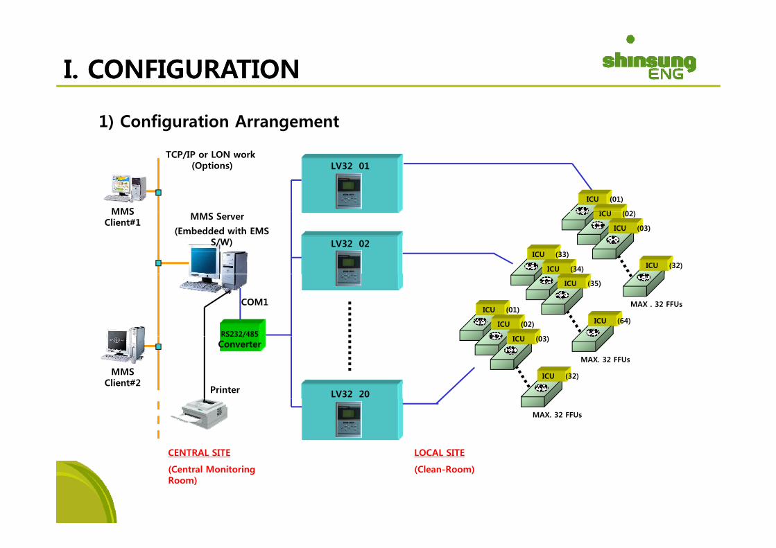
I. CONFIGURATIONI. CONFIGURATION
1) Configuration Arrangement
MMS
TCP/IP or LON work (Options) LV32 01
ICU (01)
ICU (02)MMS ServerMMS Client#1
ICU (02)
ICU (03)
ICU (32)
ICU (33)
ICU (34)
(Embedded with EMS S/W) LV32 02
COM1
RS232/485
MAX . 32 FFUsICU (01)
ICU (02)
ICU (03)
ICU (35)
ICU (64)
MMS Client#2
RS232/485Converter
ICU (03)
ICU (32)
MAX. 32 FFUs
Printer LV32 20
MAX. 32 FFUs
CENTRAL SITE LOCAL SITE
(Central Monitoring Room)
(Clean-Room)
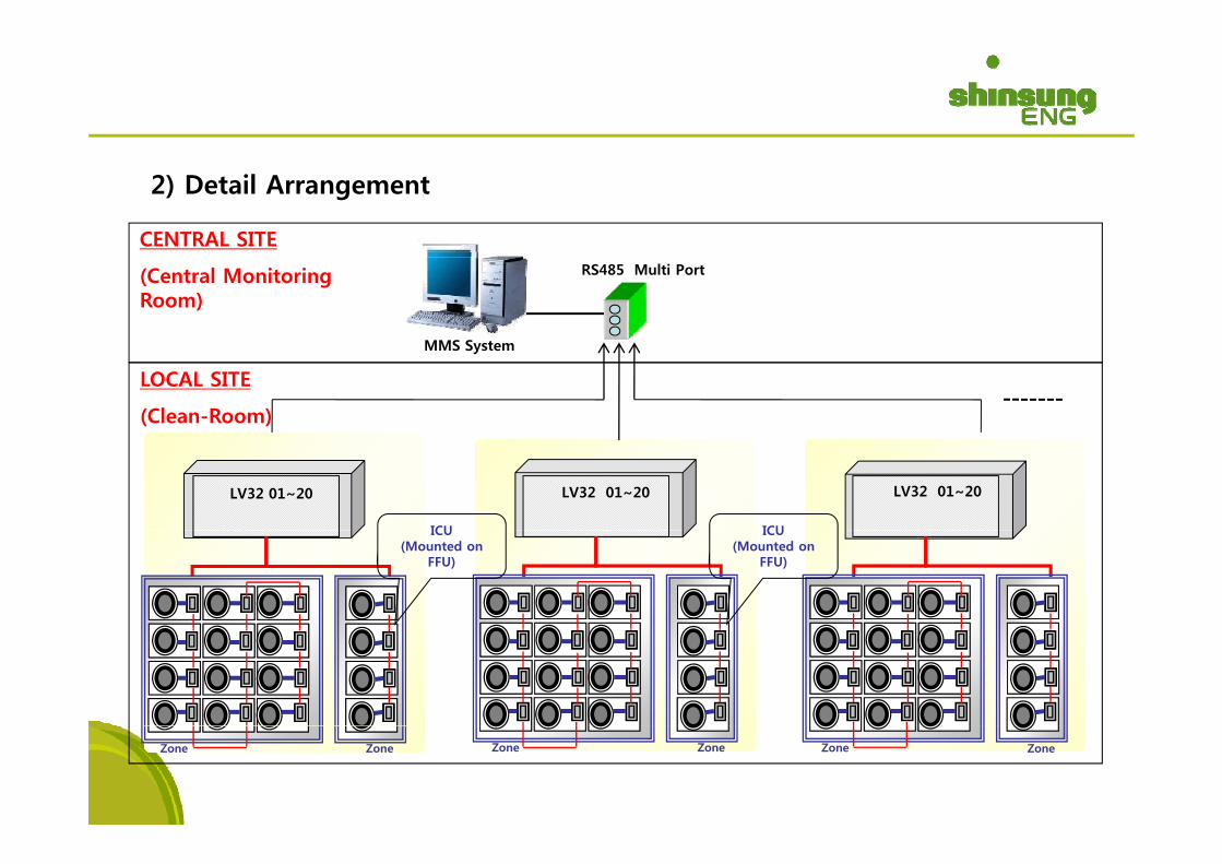
2) Detail Arrangement
CENTRAL SITECENTRAL SITE
(Central Monitoring Room)
RS485 Multi Port
MMS System
LOCAL SITE
(Clean-Room)
LV32 01~20 LV32 01~20 LV32 01~20
ICUICU ICU(Mounted on
FFU)
ICU(Mounted on
FFU)
Zone Zone Zone Zone Zone Zone
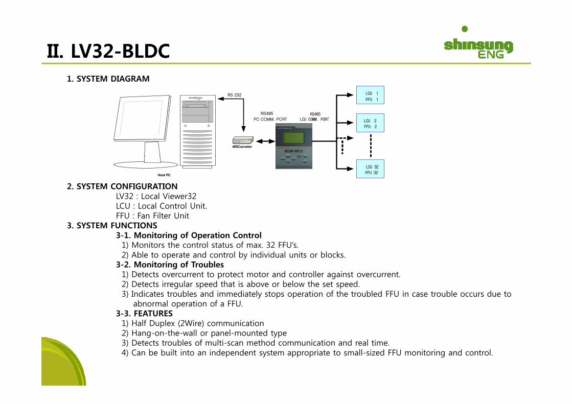
II. LV32II. LV32--BLDCBLDC1. SYSTEM DIAGRAM
RS 232 LCU 1
FFU 1
RS485LCU COMM. PORT
RS485
PC COMM. PORT
485Conveter
LCU 2
FFU 2
2. SYSTEM CONFIGURATIONLV32 : Local Viewer32
Host PC
LCU 32
FFU 32
LCU : Local Control Unit.FFU : Fan Filter Unit
3. SYSTEM FUNCTIONS 3-1. Monitoring of Operation Control
1) Monitors the control status of max. 32 FFU’s. )2) Able to operate and control by individual units or blocks.
3-2. Monitoring of Troubles1) Detects overcurrent to protect motor and controller against overcurrent. 2) Detects irregular speed that is above or below the set speed. 3) Indicates troubles and immediately stops operation of the troubled FFU in case trouble occurs due to3) Indicates troubles and immediately stops operation of the troubled FFU in case trouble occurs due to
abnormal operation of a FFU.3-3. FEATURES
1) Half Duplex (2Wire) communication 2) Hang-on-the-wall or panel-mounted type
bl f l i h d i i d l i3) Detects troubles of multi-scan method communication and real time. 4) Can be built into an independent system appropriate to small-sized FFU monitoring and control.
LV32-BLDC
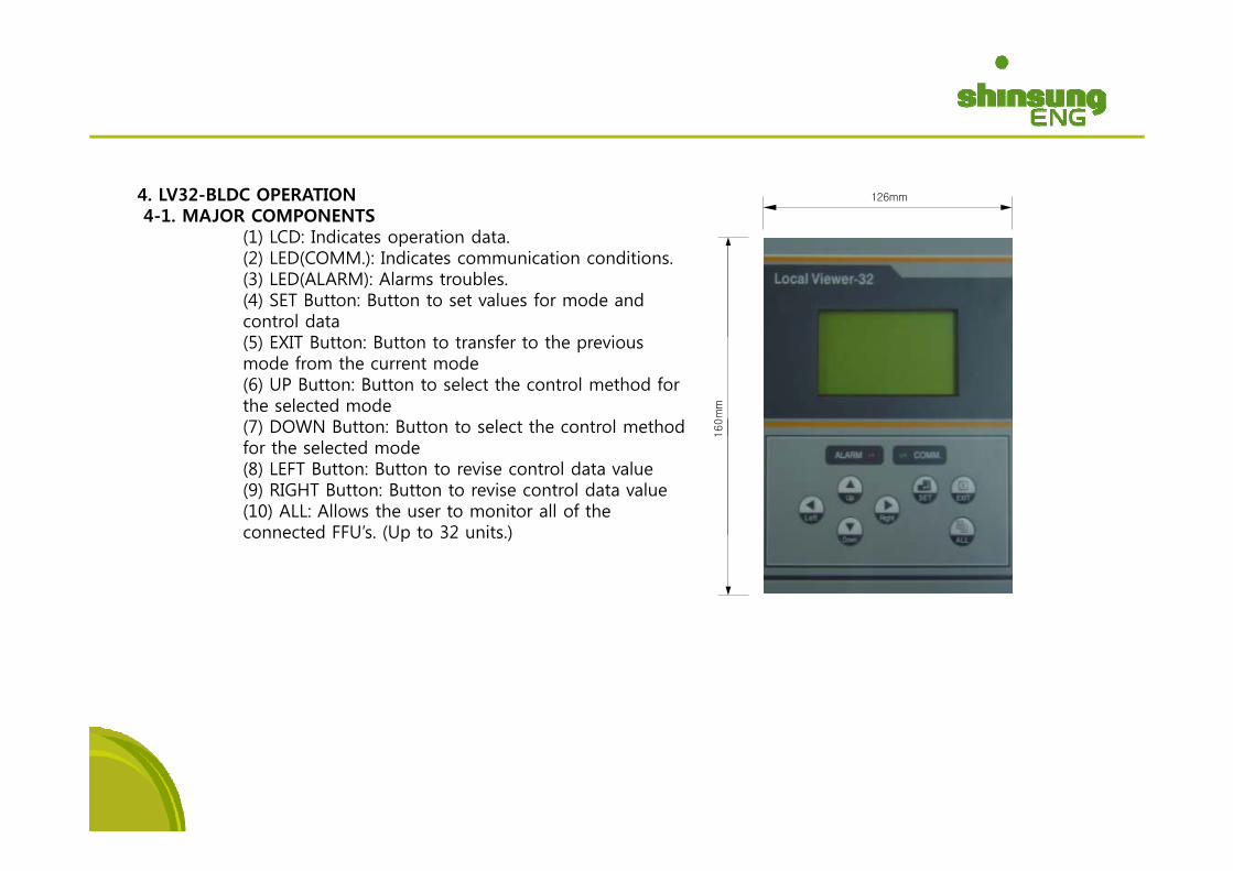
4. LV32-BLDC OPERATION4-1. MAJOR COMPONENTS
(1) LCD: Indicates operation data
126mm
(1) LCD: Indicates operation data. (2) LED(COMM.): Indicates communication conditions. (3) LED(ALARM): Alarms troubles. (4) SET Button: Button to set values for mode and control data (5) EXIT B tt B tt t t f t th i(5) EXIT Button: Button to transfer to the previous mode from the current mode(6) UP Button: Button to select the control method for the selected mode (7) DOWN Button: Button to select the control method 1
60m
m
for the selected mode(8) LEFT Button: Button to revise control data value (9) RIGHT Button: Button to revise control data value (10) ALL: Allows the user to monitor all of the connected FFU’s (Up to 32 units )
1
connected FFU s. (Up to 32 units.)
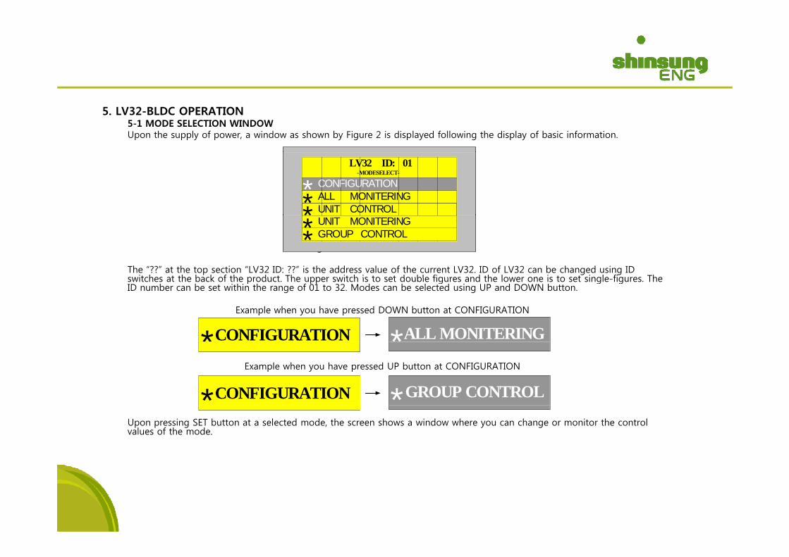
5. LV32-BLDC OPERATION5-1 MODE SELECTION WINDOW Upon the supply of power, a window as shown by Figure 2 is displayed following the display of basic information.
NC01
NC03
NC02
NC06
NC05
NC04
NC07
NC08
LV32 ID: 01-MODESELECT-
UNIT CONTROL ALL MONITERING CONFIGURATION***Figure 2. Mode Selection Window
The “??” at the top section “LV32 ID: ??” is the address value of the current LV32. ID of LV32 can be changed using ID switches at the back of the product The upper switch is to set double figures and the lower one is to set single figures The
NC27
CON GROUP CONTROL UNIT MONITERING**
CONFIGURATION* *ALL MONITERING
switches at the back of the product. The upper switch is to set double figures and the lower one is to set single-figures. The ID number can be set within the range of 01 to 32. Modes can be selected using UP and DOWN button.
Example when you have pressed DOWN button at CONFIGURATION
Example when you have pressed UP button at CONFIGURATION
CONFIGURATION* *GROUP CONTROL
Upon pressing SET button at a selected mode, the screen shows a window where you can change or monitor the control values of the mode.
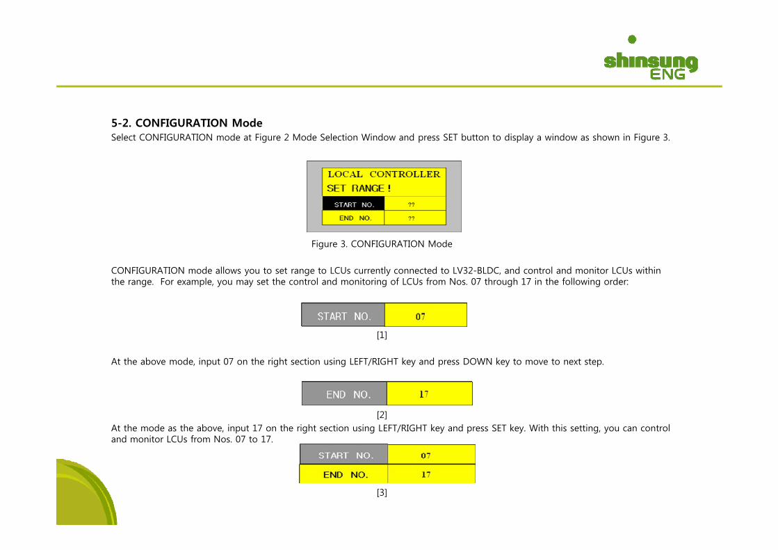
5-2. CONFIGURATION ModeSelect CONFIGURATION mode at Figure 2 Mode Selection Window and press SET button to display a window as shown in Figure 3.
Figure 3. CONFIGURATION Mode
CONFIGURATION mode allows you to set range to LCUs currently connected to LV32-BLDC, and control and monitor LCUs within y g ythe range. For example, you may set the control and monitoring of LCUs from Nos. 07 through 17 in the following order:
[1][1]
At the above mode, input 07 on the right section using LEFT/RIGHT key and press DOWN key to move to next step.
[2]At the mode as the above, input 17 on the right section using LEFT/RIGHT key and press SET key. With this setting, you can control and monitor LCUs from Nos. 07 to 17.
[3]
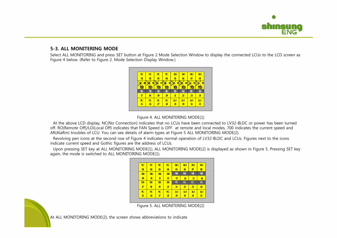
5-3. ALL MONITERING MODESelect ALL MONITORING and press SET button at Figure 2 Mode Selection Window to display the connected LCUs to the LCD screen as Figure 4 below. (Refer to Figure 2. Mode Selection Display Window.)
NC01
AR
NC03
NC02
RO06
RO05
NC04
RO07
RO08
AR AR AR ARAR ARAR
09
70010 11 12 13 14 15 16
700 700700 700700700 700
Figure 4. ALL MONITERING MODE(1)
AR19
NC27
NC26
AR17
AR18
NC25
NC28
AR20
LO30
LO29
LO31
LO32
AR22
AR21
AR24
AR23
g ( )At the above LCD display, NC(No Connection) indicates that no LCUs have been connected to LV32-BLDC or power has been turned
off. RO(Remote Off)/LO(Local Off) indicates that FAN Speed is OFF at remote and local modes, 700 indicates the current speed and AR(AlaRm) troubles of LCU. You can see details of alarm types at Figure 5 ALL MONITORING MODE(2). Revolving pen icons at the second row of Figure 4 indicates normal operation of LV32-BLDC and LCUs. Figures next to the icons
indicate current speed and Gothic figures are the address of LCUs. Upon pressing SET key at ALL MONITORING MODE(1), ALL MONITORING MODE(2) is displayed as shown in Figure 5. Pressing SET key
again, the mode is switched to ALL MONITORING MODE(1).
NC01
NC03
NC02
RO06
RO05
NC04
RO07
RO08
RR RRRR RR MEMEMEME
LR19
NC27
NC26
LR17
LR18
NC25
NC28
LR20
LO30
LO29
LO31
LO32
2221 2423
RR09
RR11
RR10
RR12 1513 1614
MEMEMEME
CLCLCL CL
Figure 5. ALL MONITERING MODE(2)
At ALL MONITORING MODE(2), the screen shows abbreviations to indicate
operating status of each FFU connected to LV32-BLDC. NC stands for No Connection, RO for Remote Off, RR for Remote Run, ME forMotor Error, LO for Local Off, LR for Local Run, CL for Current Limit. Figures are the address of LCUs. In case of an ERROR with an LCU, LED(ALARM) is lighted. Upon pressing EXIT button at ALL MON mode, the window is changed to
Mode Selection Window (Fig. 2).
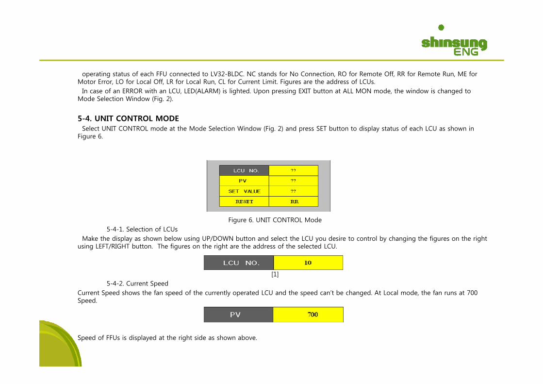
5-4. UNIT CONTROL MODESelect UNIT CONTROL mode at the Mode Selection Window (Fig. 2) and press SET button to display status of each LCU as shown in
Figure 6.
Figure 6. UNIT CONTROL Mode5-4-1. Selection of LCUs
Make the display as shown below using UP/DOWN button and select the LCU you desire to control by changing the figures on the right using LEFT/RIGHT button. The figures on the right are the address of the selected LCU.
[1]5-4-2. Current Speed
Current Speed shows the fan speed of the currently operated LCU and the speed can’t be changed. At Local mode, the fan runs at 700 Speed.
Speed of FFUs is displayed at the right side as shown above.
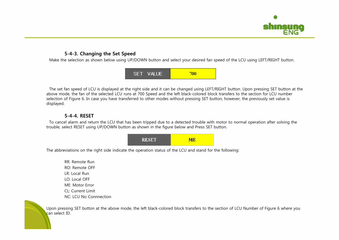
5-4-3. Changing the Set Speed Make the selection as shown below using UP/DOWN button and select your desired fan speed of the LCU using LEFT/RIGHT button.
The set fan speed of LCU is displayed at the right side and it can be changed using LEFT/RIGHT button. Upon pressing SET button at the b d th f f th l t d LCU t 700 S d d th l ft bl k l d bl k t f t th ti f LCU babove mode, the fan of the selected LCU runs at 700 Speed and the left black-colored block transfers to the section for LCU number
selection of Figure 6. In case you have transferred to other modes without pressing SET button, however, the previously set value is displayed.
5-4-4. RESETTo cancel alarm and return the LCU that has been tripped due to a detected trouble with motor to normal operation after solving the
trouble, select RESET using UP/DOWN button as shown in the figure below and Press SET button.
The abbreviations on the right side indicate the operation status of the LCU and stand for the following:
RR: Remote RunRO: Remote OFFLR: Local RunLR: Local RunLO: Local OFFME: Motor ErrorCL: Current LimitNC: LCU No Connnection
Upon pressing SET button at the above mode, the left black-colored block transfers to the section of LCU Number of Figure 6 where you can select ID.
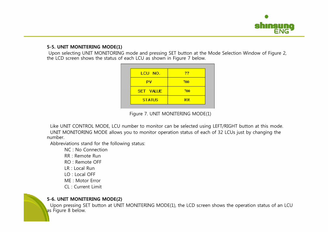
5-5. UNIT MONITERING MODE(1)Upon selecting UNIT MONITORING mode and pressing SET button at the Mode Selection Window of Figure 2, the LCD screen shows the status of each LCU as shown in Figure 7 below.
Figure 7. UNIT MONITERING MODE(1)g ( )
Like UNIT CONTROL MODE, LCU number to monitor can be selected using LEFT/RIGHT button at this mode. UNIT MONITORING MODE allows you to monitor operation status of each of 32 LCUs just by changing the
number. Abb i ti t d f th f ll i t tAbbreviations stand for the following status:
NC : No ConnectionRR : Remote RunRO : Remote OFFLR : Local RunLR : Local RunLO : Local OFFME : Motor ErrorCL : Current Limit
5-6. UNIT MONITERING MODE(2)Upon pressing SET button at UNIT MONITERING MODE(1), the LCD screen shows the operation status of an LCU
as Figure 8 below.
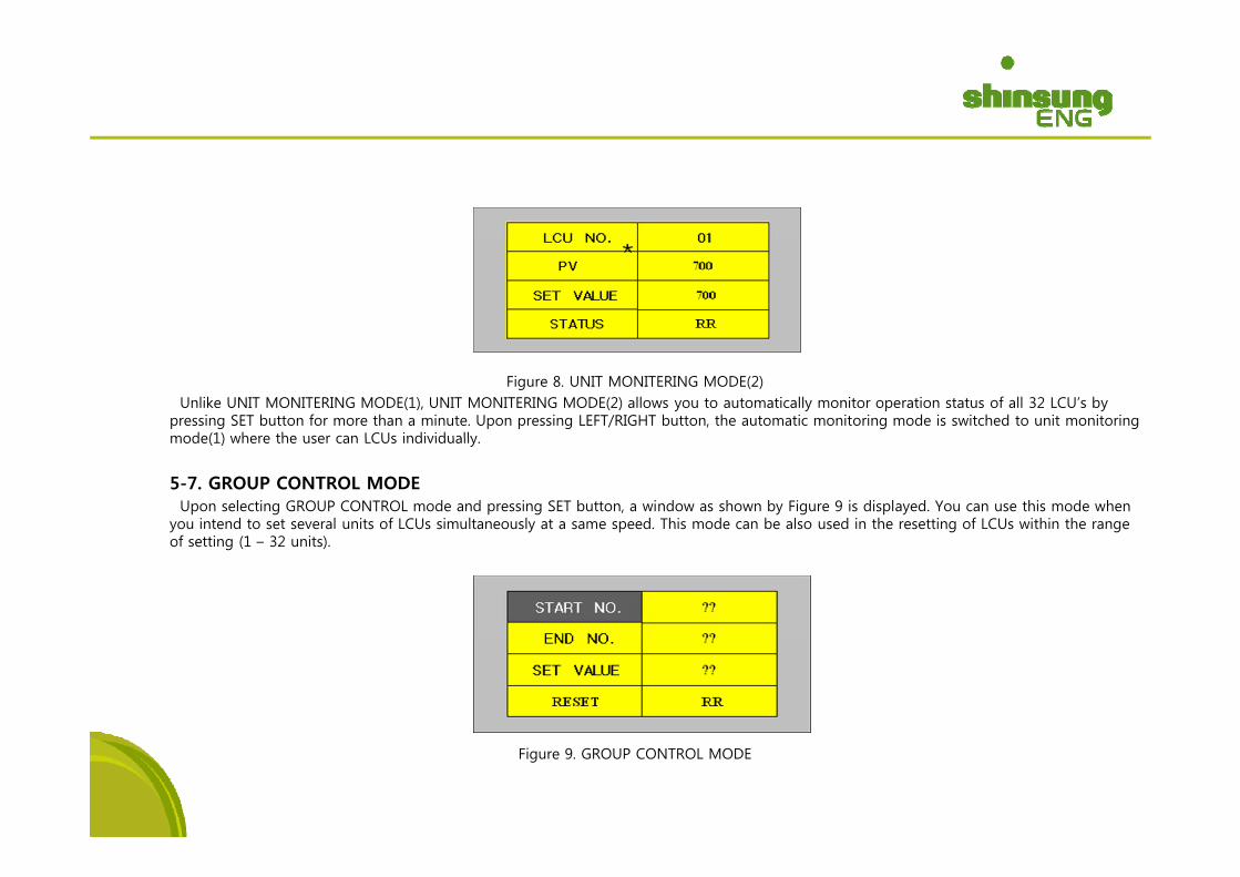
Figure 8. UNIT MONITERING MODE(2)Unlike UNIT MONITERING MODE(1), UNIT MONITERING MODE(2) allows you to automatically monitor operation status of all 32 LCU’s by
pressing SET button for more than a minute. Upon pressing LEFT/RIGHT button, the automatic monitoring mode is switched to unit monitoring mode(1) where the user can LCUs individuallymode(1) where the user can LCUs individually.
5-7. GROUP CONTROL MODEUpon selecting GROUP CONTROL mode and pressing SET button, a window as shown by Figure 9 is displayed. You can use this mode when
you intend to set several units of LCUs simultaneously at a same speed. This mode can be also used in the resetting of LCUs within the range f tti (1 32 it )of setting (1 – 32 units).
Figure 9. GROUP CONTROL MODE
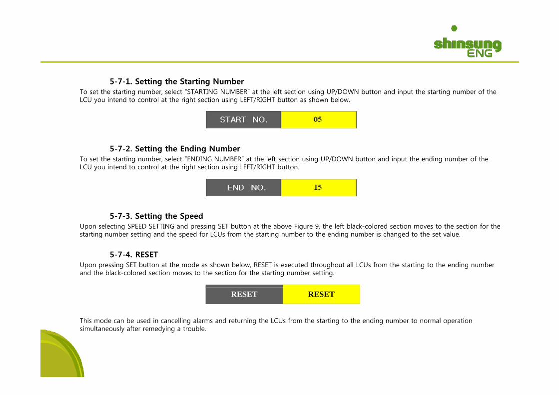
5-7-1. Setting the Starting Number To set the starting number, select “STARTING NUMBER” at the left section using UP/DOWN button and input the starting number of the LCU you intend to control at the right section using LEFT/RIGHT button as shown below.
5-7-2. Setting the Ending Number g gTo set the starting number, select “ENDING NUMBER” at the left section using UP/DOWN button and input the ending number of the LCU you intend to control at the right section using LEFT/RIGHT button.
5-7-3. Setting the Speed Upon selecting SPEED SETTING and pressing SET button at the above Figure 9, the left black-colored section moves to the section for the starting number setting and the speed for LCUs from the starting number to the ending number is changed to the set value.
5-7-4. RESETUpon pressing SET button at the mode as shown below, RESET is executed throughout all LCUs from the starting to the ending number and the black-colored section moves to the section for the starting number setting.
This mode can be used in cancelling alarms and returning the LCUs from the starting to the ending number to normal operation simultaneously after remedying a trouble.
RESET RESET
y y g
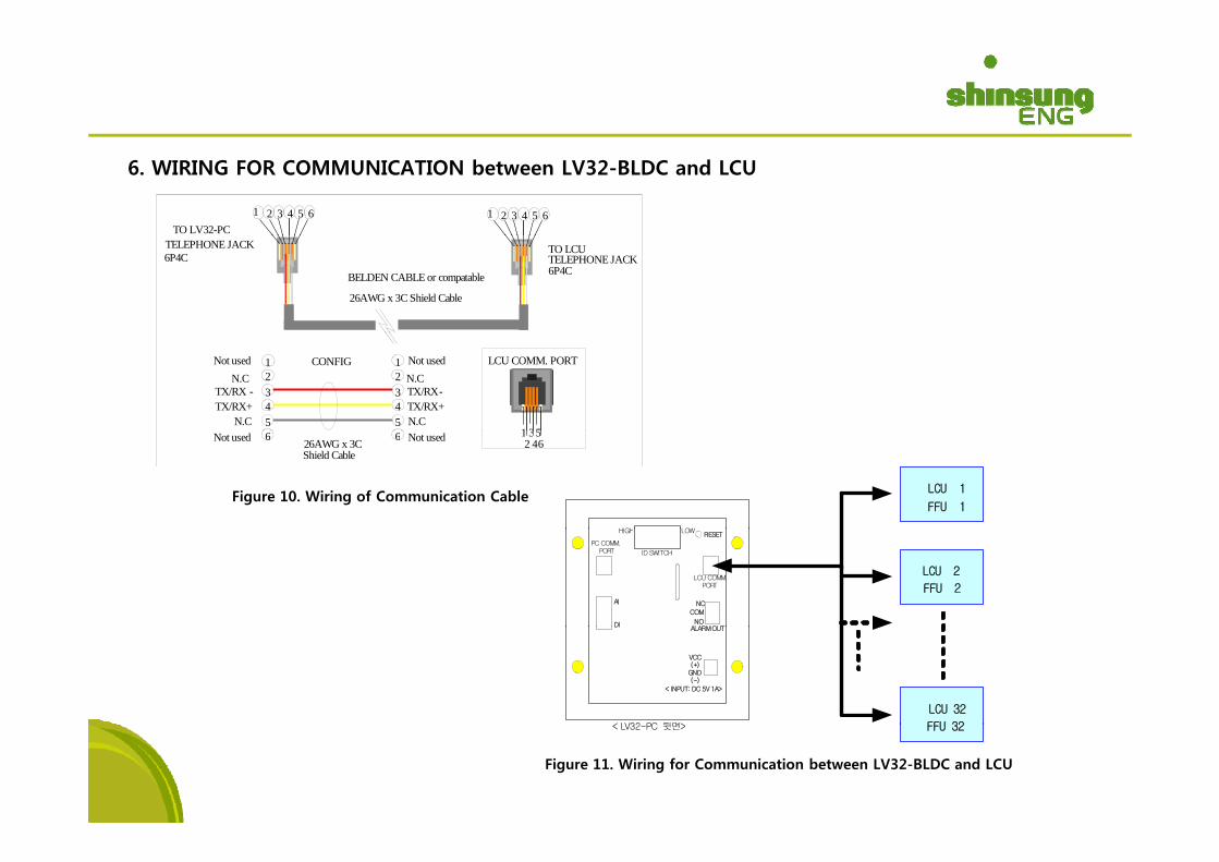
6. WIRING FOR COMMUNICATION between LV32-BLDC and LCU
TO LV32-PC1 32 4 651 32 4 65
BELDEN CABLE or compatable
26AWG x 3C Shield Cable
TELEPHONE JACK6P4C
TO LCUTELEPHONE JACK6P4C
1 35
LCU COMM. PORT
4
123
5
N.CNot used
4
123
5
N.CNot used
TX/RX -TX/RX+
N.C
TX/RX-TX/RX+N.C
CONFIG
Figure 10. Wiring of Communication Cable
1 32 46
56 Not used6Not used 26AWG x 3CShield Cable
LCU 1
FFU 1
HIGH LOW
LCU 2
FFU 2 AI
RESET
PC COMM.PORT ID SWITCH
HIGH LOW
LCU COMM.PORT
DI
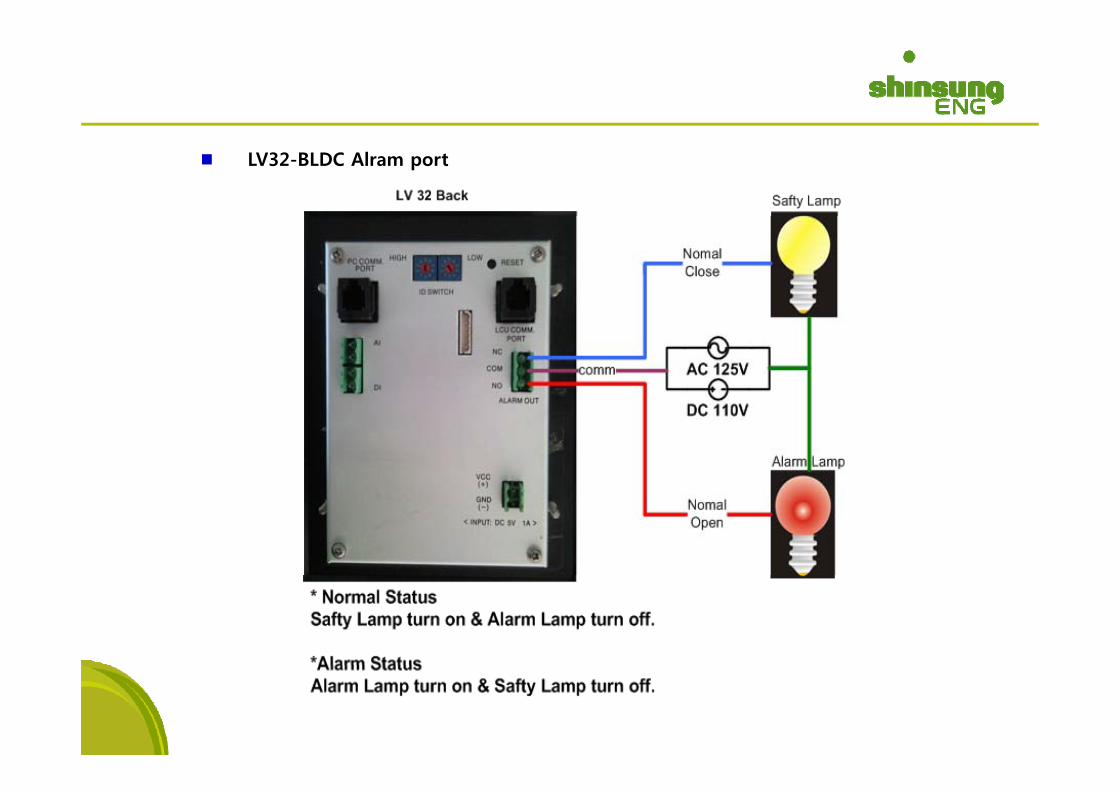
COM
NC
NOALARMOUT
LCU 32
FFU 32< LV32 PC 뒷면>
DIALARM OUT
VCC(+)
< INPUT: DC 5V 1A>
GND(-)
Figure 11. Wiring for Communication between LV32-BLDC and LCU
FFU 32 < LV32-PC 뒷면>
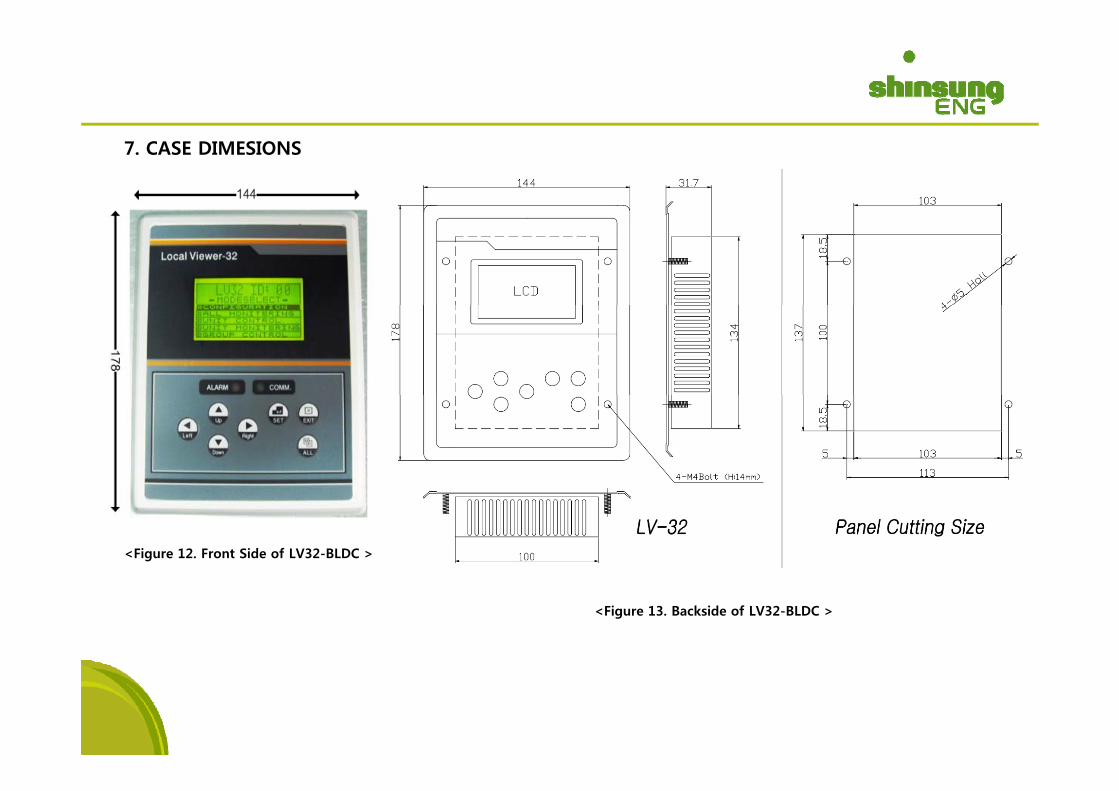
7. CASE DIMESIONS
<Figure 12. Front Side of LV32-BLDC >
<Figure 13. Backside of LV32-BLDC >
LV32-BLDC
LV32-BLDC Alram port
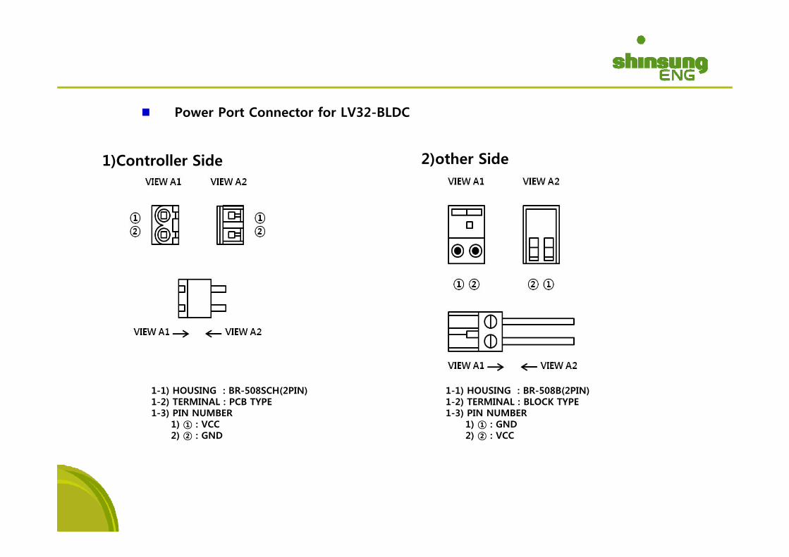
Power Port Connector for LV32-BLDC
1)Controller Side 2)other Side
1-1) HOUSING : BR-508SCH(2PIN)1-2) TERMINAL : PCB TYPE
1-1) HOUSING : BR-508B(2PIN)1-2) TERMINAL : BLOCK TYPE1 2) TERMINAL : PCB TYPE
1-3) PIN NUMBER1) ① : VCC2) ② : GND
1 2) TERMINAL : BLOCK TYPE1-3) PIN NUMBER
1) ① : GND2) ② : VCC
ICU-BL350WS
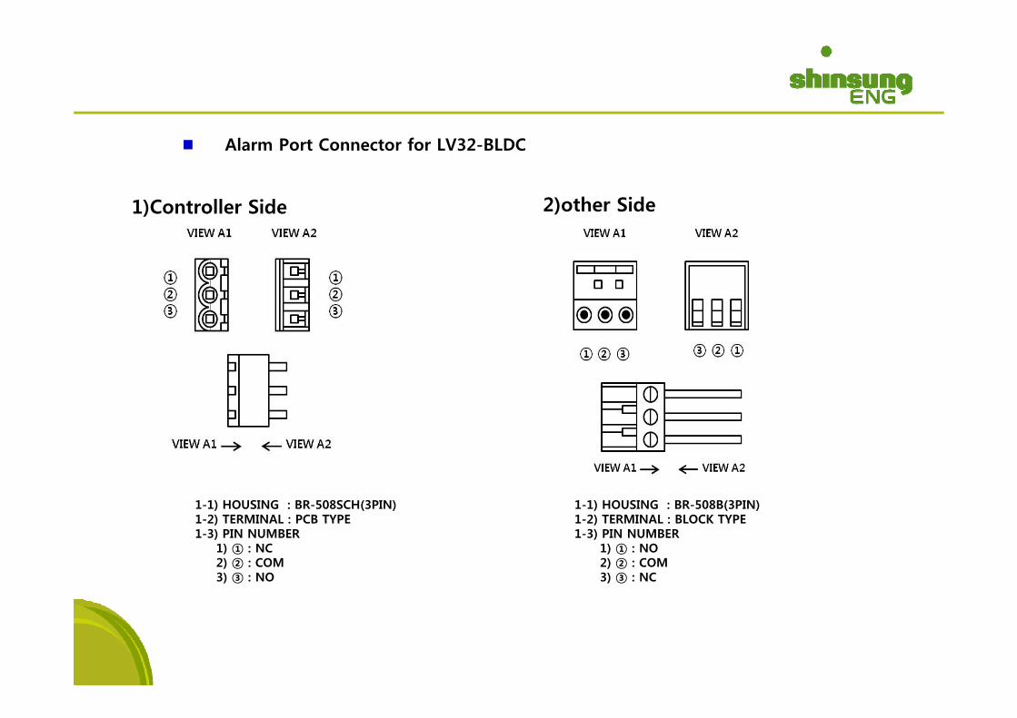
Alarm Port Connector for LV32-BLDC
1)Controller Side 2)other Side
1-1) HOUSING : BR-508B(3PIN)1-2) TERMINAL : BLOCK TYPE
1-1) HOUSING : BR-508SCH(3PIN)1-2) TERMINAL : PCB TYPE 1 2) TERMINAL : BLOCK TYPE
1-3) PIN NUMBER1) ① : NO2) ② : COM3) ③ : NC
1 2) TERMINAL : PCB TYPE1-3) PIN NUMBER
1) ① : NC2) ② : COM3) ③ : NO
ICU-BL350WSIII. ICUIII. ICU--BL350BL3501. Specification
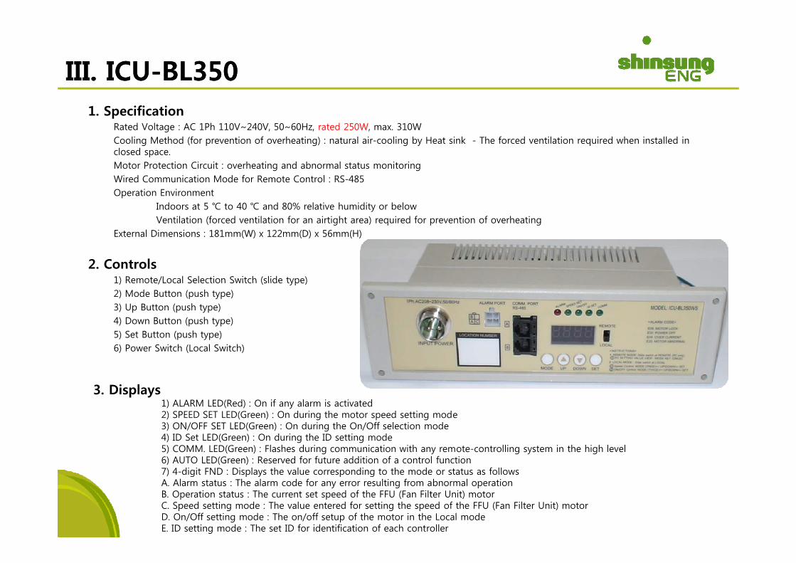
Rated Voltage : AC 1Ph 110V~240V, 50~60Hz, rated 250W, max. 310WCooling Method (for prevention of overheating) : natural air-cooling by Heat sink - The forced ventilation required when installed in closed spaceclosed space.Motor Protection Circuit : overheating and abnormal status monitoringWired Communication Mode for Remote Control : RS-485Operation Environment
Indoors at 5 ℃ to 40 ℃ and 80% relative humidity or belowV til ti (f d til ti f i ti ht ) i d f ti f h tiVentilation (forced ventilation for an airtight area) required for prevention of overheating
External Dimensions : 181mm(W) x 122mm(D) x 56mm(H)
2. Controls1) Remote/Local Selection Switch (slide type)1) Remote/Local Selection Switch (slide type)2) Mode Button (push type)3) Up Button (push type)4) Down Button (push type)5) Set Button (push type)6) P S it h (L l S it h)6) Power Switch (Local Switch)
3. Displays1) ALARM LED(Red) : On if any alarm is activated2) SPEED SET LED(Green) : On during the motor speed setting mode3) ON/OFF SET LED(Green) : On during the On/Off selection mode4) ID Set LED(Green) : On during the ID setting mode5) COMM. LED(Green) : Flashes during communication with any remote-controlling system in the high level6) AUTO LED(Green) : Reserved for future addition of a control function7) 4-digit FND : Displays the value corresponding to the mode or status as follows7) 4 digit FND : Displays the value corresponding to the mode or status as followsA. Alarm status : The alarm code for any error resulting from abnormal operationB. Operation status : The current set speed of the FFU (Fan Filter Unit) motorC. Speed setting mode : The value entered for setting the speed of the FFU (Fan Filter Unit) motorD. On/Off setting mode : The on/off setup of the motor in the Local modeE. ID setting mode : The set ID for identification of each controller
ICU-BL350WS
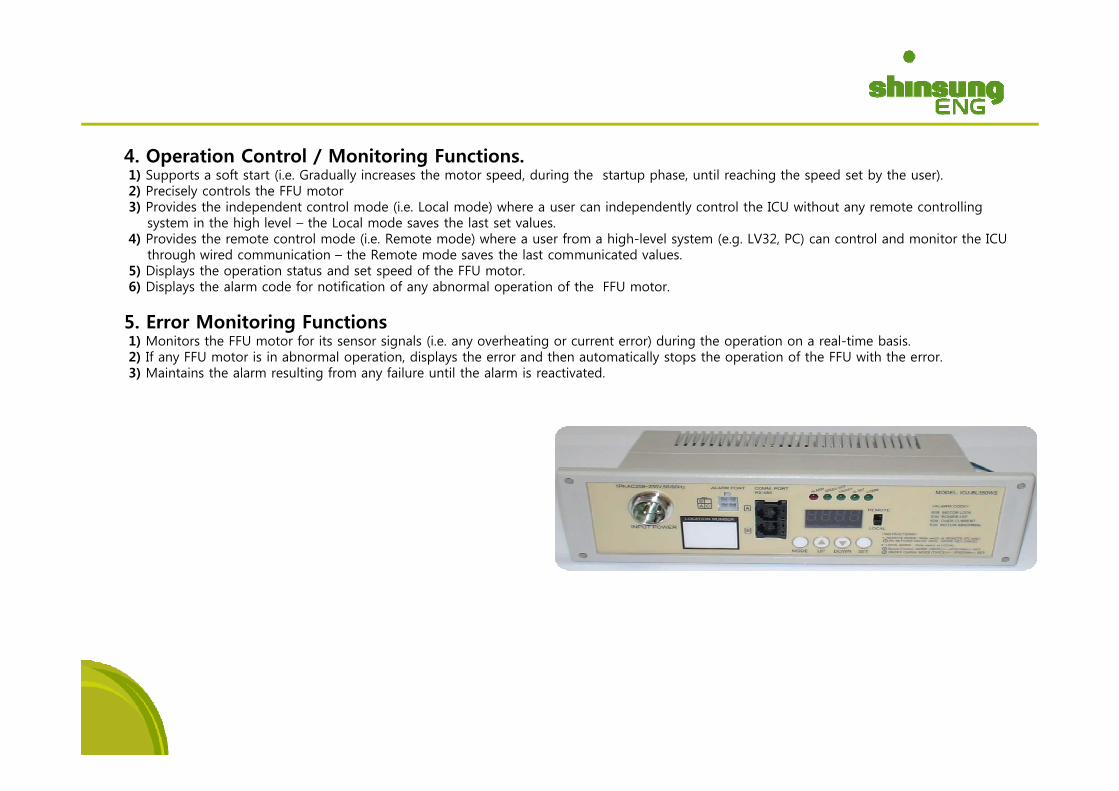
4. Operation Control / Monitoring Functions.1) Supports a soft start (i.e. Gradually increases the motor speed, during the startup phase, until reaching the speed set by the user).2) Precisely controls the FFU motor3) Provides the independent control mode (i.e. Local mode) where a user can independently control the ICU without any remote controlling
system in the high level – the Local mode saves the last set values.4) Provides the remote control mode (i.e. Remote mode) where a user from a high-level system (e.g. LV32, PC) can control and monitor the ICU
through wired communication – the Remote mode saves the last communicated values.5) Displays the operation status and set speed of the FFU motor.6) Displays the alarm code for notification of any abnormal operation of the FFU motor.
5. Error Monitoring Functions1) Monitors the FFU motor for its sensor signals (i.e. any overheating or current error) during the operation on a real-time basis.2) If any FFU motor is in abnormal operation, displays the error and then automatically stops the operation of the FFU with the error. 3) Maintains the alarm resulting from any failure until the alarm is reactivated.
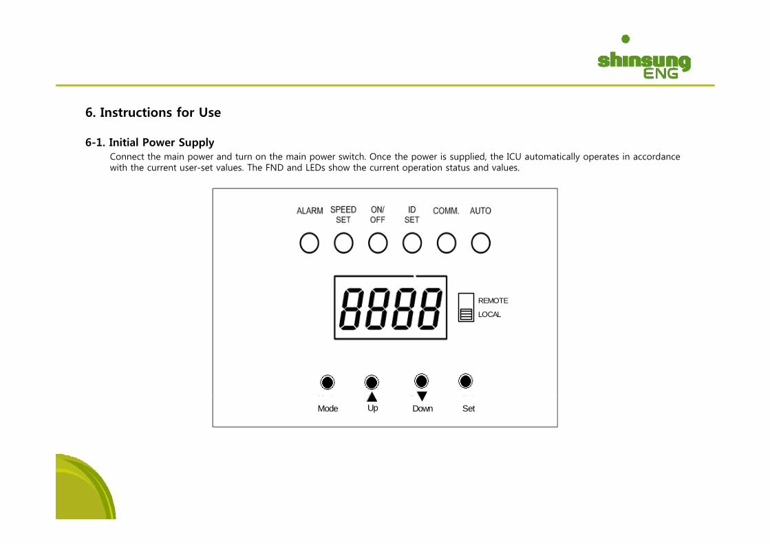
6. Instructions for Use
6-1. Initial Power Supplypp yConnect the main power and turn on the main power switch. Once the power is supplied, the ICU automatically operates in accordance with the current user-set values. The FND and LEDs show the current operation status and values.
REMOTE
LOCAL
Mode Up Down Set
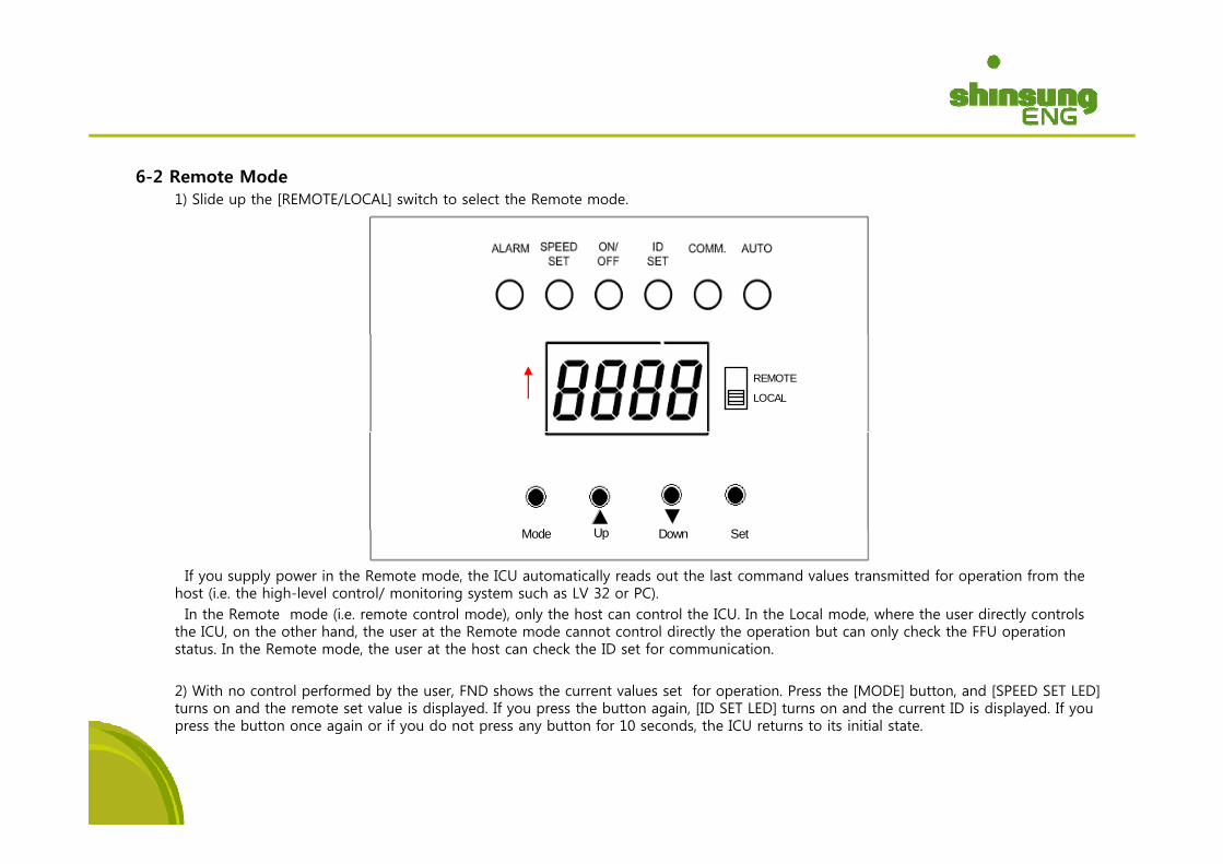
6-2 Remote Mode1) Slide up the [REMOTE/LOCAL] switch to select the Remote mode.
REMOTE
LOCAL
M d U D S t
If you supply power in the Remote mode, the ICU automatically reads out the last command values transmitted for operation from the host (i.e. the high-level control/ monitoring system such as LV 32 or PC). In the Remote mode (i.e. remote control mode), only the host can control the ICU. In the Local mode, where the user directly controls
th ICU th th h d th t th R t d t t l di tl th ti b t l h k th FFU ti
Mode Up Down Set
the ICU, on the other hand, the user at the Remote mode cannot control directly the operation but can only check the FFU operation status. In the Remote mode, the user at the host can check the ID set for communication.
2) With no control performed by the user, FND shows the current values set for operation. Press the [MODE] button, and [SPEED SET LED] turns on and the remote set value is displayed. If you press the button again, [ID SET LED] turns on and the current ID is displayed. If you press the button once again or if you do not press any button for 10 seconds the ICU returns to its initial statepress the button once again or if you do not press any button for 10 seconds, the ICU returns to its initial state.
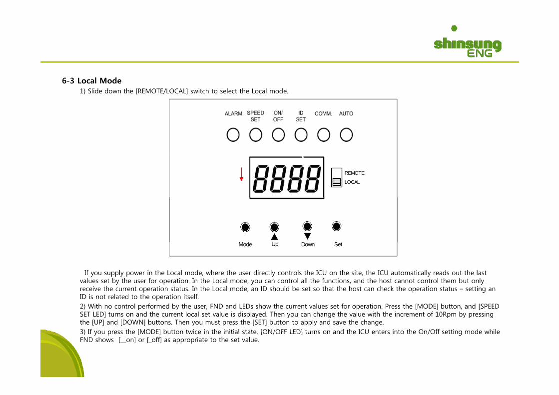
6-3 Local Mode1) Slide down the [REMOTE/LOCAL] switch to select the Local mode.
REMOTE
LOCAL
M d U D S t
If you supply power in the Local mode, where the user directly controls the ICU on the site, the ICU automatically reads out the last values set by the user for operation. In the Local mode, you can control all the functions, and the host cannot control them but only
i th t ti t t I th L l d ID h ld b t th t th h t h k th ti t t tti
Mode Up Down Set
receive the current operation status. In the Local mode, an ID should be set so that the host can check the operation status – setting an ID is not related to the operation itself.2) With no control performed by the user, FND and LEDs show the current values set for operation. Press the [MODE] button, and [SPEED SET LED] turns on and the current local set value is displayed. Then you can change the value with the increment of 10Rpm by pressing the [UP] and [DOWN] buttons. Then you must press the [SET] button to apply and save the change.3) If you press the [MODE] button twice in the initial state [ON/OFF LED] turns on and the ICU enters into the On/Off setting mode while3) If you press the [MODE] button twice in the initial state, [ON/OFF LED] turns on and the ICU enters into the On/Off setting mode while FND shows [__on] or [_off] as appropriate to the set value.
You can change the set value to On and Off by pressing the [UP] and[DOWN] buttons, respectively. If you press the [SET] button, the change is saved and the On/Off setting mode is finished. You can turn on and off the ICU while
maintaining the local set values if you use the On/Off setting mode.4) If you press the [MODE] button three times [ID SET LED] turns on and FND shows the current set ID Then you can change the ID4) If you press the [MODE] button three times, [ID SET LED] turns on and FND shows the current set ID. Then you can change the ID from 1 to 64 by pressing the [UP] and [DOWN] buttons. You must press the [SET] button to save the changed ID.
6-4 Alarm Messages1) Alarm CodesE 04 M lE-04 : Motor overcurrent alarm E-08 : Motor abnormal alarm (Motor bound alarm when motor RPM is lower than low limit for the assigned time.)E-20 : Motor abnormal alarm (when hall breaking of wire, short circuit, power supply noise and surge flow to output switching and occur)2) Terminating an Error (i.e. Deactivating an Alarm)Examine the motor in the Local mode, solve any problem, and press the Mode and Set buttons in order, to initialize and restart the system.
* Note : Alarm messages may vary to the functions and specifications of the motor used.
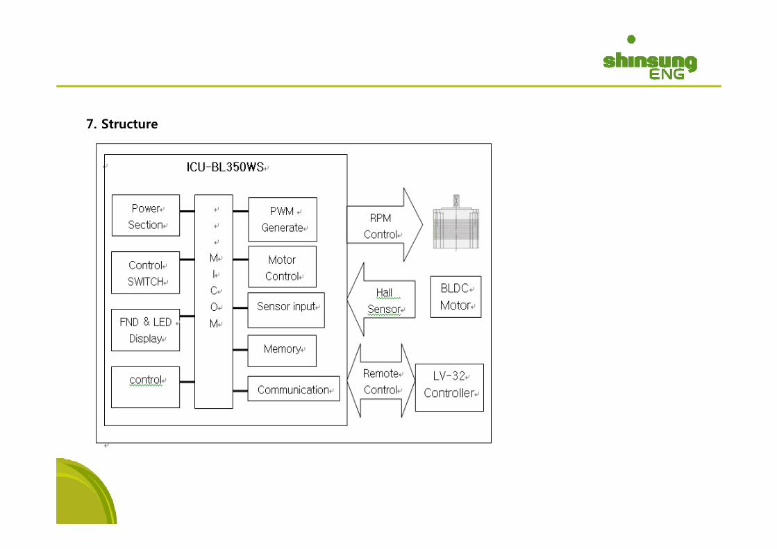
7. Structure
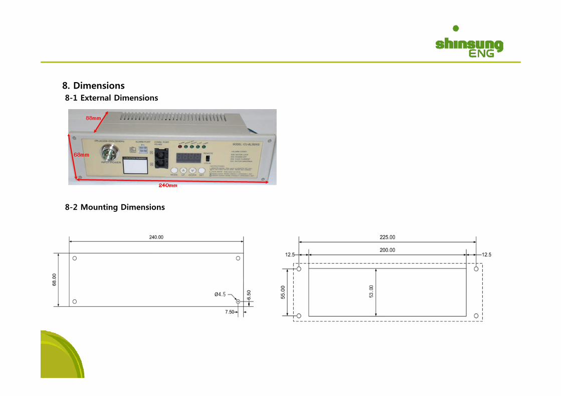
8. Dimensions8-1 External Dimensions
8-2 Mounting Dimensions
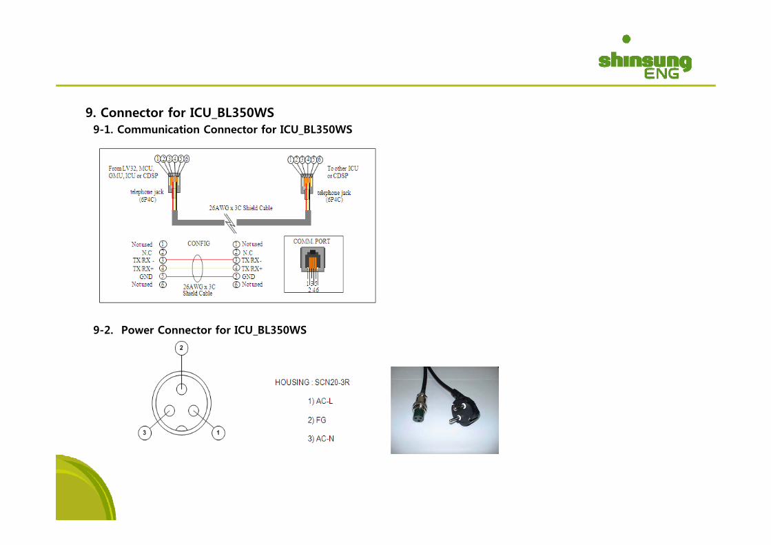
9. Connector for ICU_BL350WS9-1. Communication Connector for ICU_BL350WS
9-2. Power Connector for ICU BL350WS_
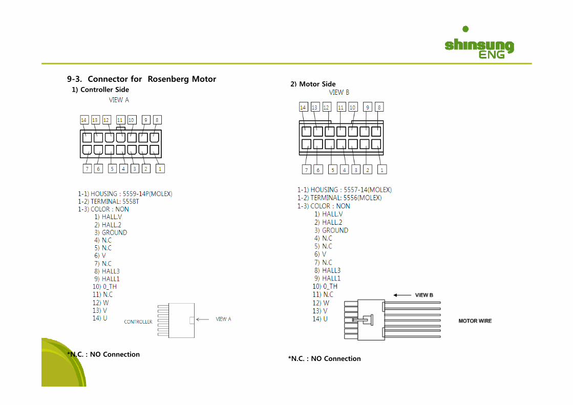
9-3. Connector for Rosenberg Motor1) Controller Side
2) Motor Side
*N.C. : NO Connection*N.C. : NO Connection
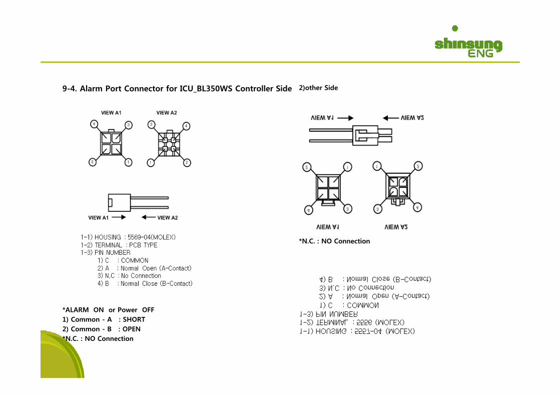
9-4. Alarm Port Connector for ICU_BL350WS Controller Side 2)other Side
*N.C. : NO ConnectionN.C. : NO Connection
*ALARM ON or Power OFF1) Common - A : SHORT2) Common - B : OPEN*N.C. : NO Connection