Embed Size (px)
Citation preview
Shining a Light on Human Pose:
On Shadows, Shading and the Estimation of Pose and Shape
Alexandru O. Balan∗ Michael J. Black∗ Horst Haussecker† Leonid Sigal∗
∗Department of Computer Science, Brown University, Providence, RI 02912, USA†Intel Corporation, Santa Clara, CA 95054, USA
{alb, black, ls}@cs.brown.edu; [email protected]
Abstract
Strong lighting is common in natural scenes yet is often
viewed as a nuisance for object pose estimation and track-
ing. In human shape and pose estimation, cast shadows can
be confused with foreground structure while self shadowing
and shading variation on the body cause the appearance
of the person to change with pose. Rather than attempt to
minimize the effects of lighting and shadows, we show that
strong lighting in a scene actually makes pose and shape
estimation more robust. Additionally, by recovering multi-
ple body poses we are able to automatically estimate the
lighting in the scene and the albedo of the body. Our ap-
proach makes use of a detailed 3D body model, the param-
eters of which are directly recovered from image data. We
provide a thorough exploration of human pose estimation
under strong lighting conditions and show: 1. the estima-
tion of the light source from cast shadows; 2. the estimation
of the light source and the albedo of the body from multiple
body poses; 3. that a point light and cast shadows on the
ground plane can be treated as an additional “shadow cam-
era” that improves pose and shape recovery, particularly in
monocular scenes. Additionally we introduce the notion of
albedo constancy which employs lighting normalized image
data for matching. Our experiments with multiple subjects
show that rather than causing problems, strong lighting im-
proves human pose and shape estimation.
1. Introduction
Strong illumination is often seen as a problem for pose
estimation and tracking; this is particularly true for human
pose estimation. In contrast, we show that, rather than
hinder human pose and shape estimation, strong illumina-
tion can actually make it more robust. With a known light
source, shadows and shading provide additional constraints
for pose estimation and tracking. Conversely, if one has ac-
curate pose estimates, we can estimate the light source lo-
Figure 1. The Shadow Camera. Shadows cast on the ground may
reveal structure not directly observed on an object such as the right
arm or the left leg of the person in the image. The light together
with the ground plane act like another camera view providing an
additional silhouette of the object.
cation and reflectance properties of the body. Putting both
of these observations together results in a complete frame-
work for incorporating strong illumination in human pose
estimation. These ideas, however, are applicable to object
detection and tracking in general.
Consider the situation in which the scene is illuminated
by a single, known, point light source and is viewed through
one, or more, calibrated cameras. Here we focus on indoor
scenes where the light source distance is finite. The ap-
proach, however, easily generalizes to distant light sources,
the most common being the sun in outdoor scenes. Our
first observation is that a point light source and the ground
plane form what we call a shadow camera. The point light
acts like the focal point of a pinhole camera with the ground
plane acting like the image plane. The image formed on the
ground is the shadow cast by the body (Figure 1). This can
be generalized to multiple light sources (which effectively
produce a “camera” with multiple focal points). The cast
shadow image acts like a foreground silhouette mask in the
image plane of a regular camera. Note, moreover, the “im-
age plane” of the shadow camera need not be planar but can
1
be any calibrated surface (or surfaces) in the scene. This
shadow image provides additional constraints on body pose
which make it possible to estimate 3D pose from monocular
camera views.
Making use of shadows requires the accurate segmenta-
tion of shadow regions in images. To that end we propose
a novel approach that uses background subtraction data and
checks whether putative shadow pixels are consistent with
being on the calibrated ground plane. For a complete frame-
work, we must also estimate the lighting in the scene auto-
matically. We propose two approaches that exploit 3D body
pose and shape represented using the SCAPE model [1],
the parameters of which are estimated directly from image
foreground silhouettes (without knowledge of scene illumi-
nation) [3].
The first approach recovers a point light position (or di-
rection) from cast shadows. Using the known body pose in
multiple frames and the detected shadow regions, we opti-
mize for the light position that best explains the cast shad-
ows. The second approach goes a step further and recovers
both the light position, relative illumination strength, and
albedo of the body. The key idea is the following: If we
see the body in many different poses, then points on the
body are seen at different orientations with respect to the
unknown lighting. We assume that the albedo of the body
does not change with pose and that any change in the ap-
pearance of a point on the body is due solely to its change
in orientation with respect to the light. Combining many
poses gives strong constraints on the location of the light,
the albedo of the body and the background illumination in
the scene. Hence by tracking an object with fixed lighting
we can actually infer the lighting; in this way the human
body becomes a light probe [4].
Finally we show that knowing the illumination allows us
to remove the effects of lighting from images of the body.
Given an estimated light position, light intensity, and back-
ground illumination, we solve for the albedo of points on the
body in a given view. Then, rather than formulate the body
tracking problem in terms of brightness constancy, we do so
using albedo constancy and show that albedo constancy is
less sensitive to changes in body pose.
We present results on multiple sequences with three light
configurations and two subjects. A quantitative evaluation
of pose estimation under different numbers of cameras and
different numbers of point light sources is also provided.
1.1. Related Work
There is a long history of recovering lighting and using
it to infer 3D structure. This work includes shape-from-
shading, photometric stereo, shadow carving, inverse light-
ing, and reflectance modeling. A thorough survey is beyond
the scope of this paper and the reader is referred to [7] for
an overview.
Our work is quite different from to the majority of work
in shape, shading and lighting. Most approaches assume a
fixed object which is viewed under different lighting con-
ditions. The most common approaches attempt to estimate
object shape from multiple images of a static object illumi-
nated from different light locations (for example [5, 14]);
in many cases these light locations are known. We turn this
standard problem around and use multiple known poses (i.e.
estimated from data) of the object to estimate the unknown
lighting.
The most closely related work is that of [7] which esti-
mates light sources and albedos using multiple views of an
object. They assume a rigid object but move the camera to
track it. This is similar to our case where the camera is static
but the object moves. We go beyond their work to deal with
an articulated non-rigid object which casts shadows on it-
self and the ground plane. They also only restrict attention
to infinitely distant light sources and assume the depth vari-
ation of the object is small. In our case the light is a finite
distance from the object (e.g. ceiling hight) and the depth
variation of the human body relative to the lighting distance
is not negligible.
There are also many shape-from-shading and structured
light methods that are related but beyond the scope of this
paper (see [6, 15]). The most related method is that of
Mercier et al. [8] which assumes unknown shape, re-
flectance and lighting. Like us they use silhouettes to re-
construct shape but unlike us use a voxel representation.
They go beyond work here to recover more general re-
flectance models but have a much more limited capture en-
vironment and do not cope with the complexities of non-
rigid and articulated objects. Our work could be extended
to include their more general reflectance model. In related
work Savarese et al. [10] use known light sources and es-
timate an unknown shape. In our case, we know the object
shape in multiple frames and estimate the lighting.
There has been little work on articulated pose estimation
from cast shadows. Segen and Kumar [11] describe a sys-
tem to recognize basic hand gestures by tracking the 3D po-
sition and orientation of two fingers using the hand shadow
captured with a single camera. More relevant is the work
of Bruckstein et al. [2] in which they geometrically recover
the pose of an articulated human stick figure and the light
position from shadows. The approach requires the skeletal
joints, and their corresponding locations on the shadow, to
be manually marked in the image.
We apply a different strategy and define an objective
function over the parametric pose and shape of the subject
and the point light source position such that the projection
of the shape onto the image silhouette and the shadow best
overlap the observed body regions. We believe this to be
the first automatic procedure to estimate articulated human
pose and shape by taking advantage of cast shadows.
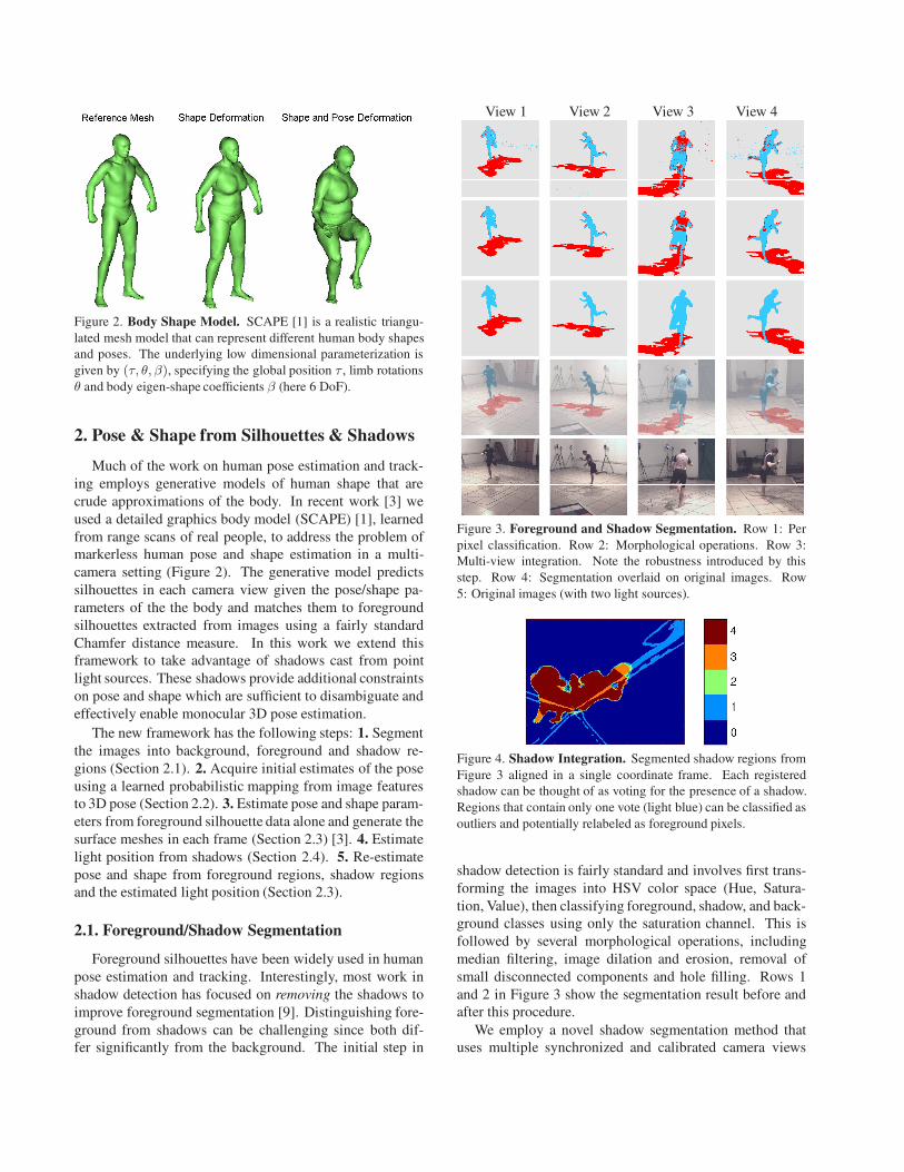
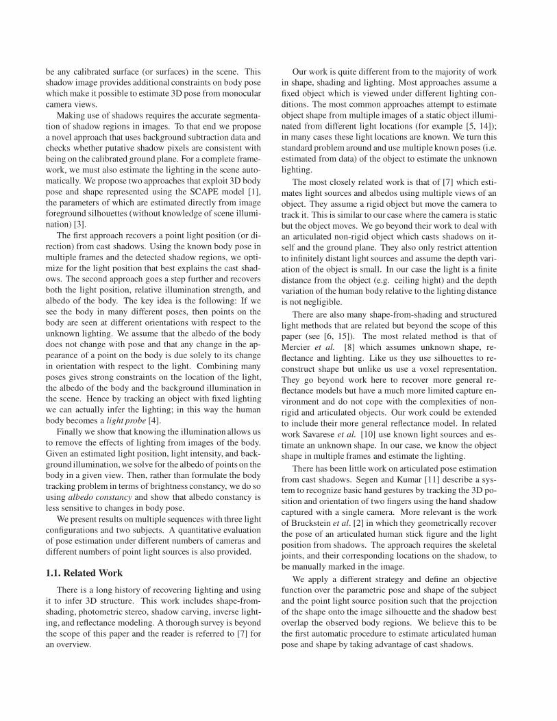
Figure 2. Body Shape Model. SCAPE [1] is a realistic triangu-
lated mesh model that can represent different human body shapes
and poses. The underlying low dimensional parameterization is
given by (τ, θ, β), specifying the global position τ , limb rotations
θ and body eigen-shape coefficients β (here 6 DoF).
2. Pose & Shape from Silhouettes & Shadows
Much of the work on human pose estimation and track-
ing employs generative models of human shape that are
crude approximations of the body. In recent work [3] we
used a detailed graphics body model (SCAPE) [1], learned
from range scans of real people, to address the problem of
markerless human pose and shape estimation in a multi-
camera setting (Figure 2). The generative model predicts
silhouettes in each camera view given the pose/shape pa-
rameters of the the body and matches them to foreground
silhouettes extracted from images using a fairly standard
Chamfer distance measure. In this work we extend this
framework to take advantage of shadows cast from point
light sources. These shadows provide additional constraints
on pose and shape which are sufficient to disambiguate and
effectively enable monocular 3D pose estimation.
The new framework has the following steps: 1. Segment
the images into background, foreground and shadow re-
gions (Section 2.1). 2. Acquire initial estimates of the pose
using a learned probabilistic mapping from image features
to 3D pose (Section 2.2). 3. Estimate pose and shape param-
eters from foreground silhouette data alone and generate the
surface meshes in each frame (Section 2.3) [3]. 4. Estimate
light position from shadows (Section 2.4). 5. Re-estimate
pose and shape from foreground regions, shadow regions
and the estimated light position (Section 2.3).
2.1. Foreground/Shadow Segmentation
Foreground silhouettes have been widely used in human
pose estimation and tracking. Interestingly, most work in
shadow detection has focused on removing the shadows to
improve foreground segmentation [9]. Distinguishing fore-
ground from shadows can be challenging since both dif-
fer significantly from the background. The initial step in
View 1 View 2 View 3 View 4
Figure 3. Foreground and Shadow Segmentation. Row 1: Per
pixel classification. Row 2: Morphological operations. Row 3:
Multi-view integration. Note the robustness introduced by this
step. Row 4: Segmentation overlaid on original images. Row
5: Original images (with two light sources).
Figure 4. Shadow Integration. Segmented shadow regions from
Figure 3 aligned in a single coordinate frame. Each registered
shadow can be thought of as voting for the presence of a shadow.
Regions that contain only one vote (light blue) can be classified as
outliers and potentially relabeled as foreground pixels.
shadow detection is fairly standard and involves first trans-
forming the images into HSV color space (Hue, Satura-
tion, Value), then classifying foreground, shadow, and back-
ground classes using only the saturation channel. This is
followed by several morphological operations, including
median filtering, image dilation and erosion, removal of
small disconnected components and hole filling. Rows 1
and 2 in Figure 3 show the segmentation result before and
after this procedure.
We employ a novel shadow segmentation method that
uses multiple synchronized and calibrated camera views
of the scene and a calibrated ground plane on which the
shadow is cast. It is based on the observation that each
shadow pixel corresponds to a 3D ray which can be in-
tersected with the ground plane with known coordinates.
Therefore each camera view yields a 3D reconstruction of
the shadow.
Ideally, the 3D image of the shadow is the same in all
views. In practice, the segmented shadow regions differ due
to noise in the segmentation and the fact that the body may
occlude the shadow from some camera views. We think of
the recovered shadow in each view as voting for the true 3D
shadow as illustrated in Figure 4. Inconsistent 3D shadow
reconstructions result, in part, from mislabeling foreground
as shadow. For example, in Figure 3, View 3, most of the
torso is detected as shadow, yet it is not consistent with the
shadow reconstructions in the other views.
We adopt a conservative approach and attempt to relabel
inconsistent shadow regions only when it leads to a spatially
consistent foreground segmentation. More precisely, we re-
label shadow pixels as foreground when they not explained
by the other shadow views and are adjacent to foreground
pixels in the current view. This step may alter the shadow
vote outcome. Consequently, the procedure is repeated until
convergence (typically 3 to 5 iterations), resulting in robust
and clean segmentations (see Figure 3).
2.2. Initialization of Pose
Our optimization strategy requires an initial estimate of
the pose that is relatively close to the true configuration. In
[3] we relied on a cylindrical body model to perform hu-
man tracking and initialize the SCAPE optimization. This
was shown to work well in a multi-camera setup, but still re-
quired initialization at the first frame. Here we adopt a fully
automatic strategy that is able to cope with pose ambigui-
ties in monocular sequences. We use a Bayesian Mixture of
Experts (BME) framework [13] to learn a direct non-linear
probabilistic mapping from image features to the 3D pose.
The image (shape context) features are computed from fore-
ground silhouettes in one or more views. While we can
sample multiple initial poses from this model, we choose
only the most likely here and assume the body shape is the
mean shape in the SCAPE model.
2.3. Optimization
Our goal is to estimate the shape and pose of the body
along with the the light position(s) from one or more im-
ages; we do so within a framework of synthesis and evalua-
tion. Given a a predicted body shape and pose described by
the state vector s = (τ, θ, β) (see Figure 1), we project the
3D surface mesh into the image plane of camera i to pro-
duce an estimated foreground Fei (s). This is then compared
with the observed foreground Foi . Given a light position
c, ground plane g, and a canonical view i, the estimated
shadow, Se(s, c, g), of the surface mesh on the ground is
rendered in view i and compared with the observed shadow
So (where So is the shadow derived from multiple views and
transformed into the canonical view (e.g. Fig. 4)).
To estimate the model and light parameters, we formu-
late an objective function in terms of a silhouette dissim-
ilarity measure, D(·e,·o), which is implemented as a bi-
directional Chamfer distance between estimated and ob-
served silhouettes [3]. In [3] we rely on foreground silhou-
ettes alone to estimate pose and shape; here we add a term
to measure the shadow difference. To optimize pose and
shape from silhouettes and shadows we minimize
E(s) = D(
Se(s, c, g), So)
+
K∑
i=1
D(
Fei (s), Fo
i
)
(1)
where K one or four camera views in our experiments. In
all cases, the optimization is performed using a stochastic
search technique related to annealed particle filtering as de-
scribed in [3].
2.4. Estimating the Light Position
To estimate light position, we first compute the pose and
shape, st , for some number of time instants t = 1 . . .N in a
sequence. Keeping pose and shape fixed, we then optimize
for the light positionc by minimizing the silhouette distance
E(c) =∑
t
D(
Se (st, c, g) , Sot
)
(2)
where the difference is computed between the shadow pre-
dicted by the model, Se(st, c, g), and the one computed
from the image(s) at time t, Sot .
To initialize the search we parameterize the light loca-
tion by its height from the floor and its azimuth and eleva-
tion angles. We discretize the space in a reasonable range
above the person and compute the value of (2) for a total
of 288 light positions. We then select the best location,
re-discretize around it using a 7 × 7 × 7 grid with a finer
sampling, and repeat down to a 5mm discretization.
2.5. Results
The experiments here use three sequences, (R1, R2 and
R1,2), the first two with different individual light sources,
and the third having both lights turned on. Each sequence
was captured by four synchronized and calibrated color
cameras. Sequences R1 and R1,2 are of subject AB while
R2 contains subject MB. In all cases we fit the parameters of
a SCAPE body model, independently in each frame, as de-
scribed in [3]. Ground truth light positions were computed
using a commerical motion capture system.
Light estimation results: We first show how the light
position can be estimated from the body model and ex-
tracted shadows. In each sequence the shape and pose of
1 2 3 4 5 60
20
40
60
80
100
120
140
160
180
200
Configuration
Mean J
oin
t E
rror
(mm
)
Pose Estimation Comparison
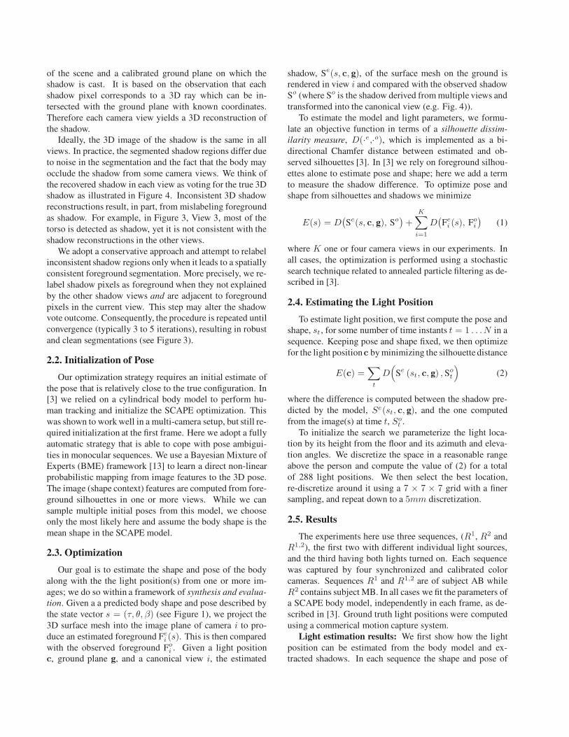
1. monocular, no shadows − 128 ± 54 mm
2. monocular, one shadow − 64 ± 14 mm
3. monocular, two shadows − 82 ± 12 mm
4. four views, no shadows − 54 ± 8 mm
5. four views, one shadow − 53 ± 6 mm
6. four views, two shadows − 66 ± 8 mm
Figure 5. Effect of shadows on pose and shape estimation. Left (R1, AB) and Middle (R2, MB): Monocular shape and pose estimation.
Row 1 shows the automatic initialization (Section 2.2). Row 2 shows estimated pose and shape based on monocular silhouette optimization.
Row 3 shows the improvement obtained by adding shadows to the optimization. Color key: amber = F e; mid-blue = F o; red = agreement
between F o and F e; light green = Se ; light blue = So; orange = agreement between So and Se . The estimation uses only the left-most
view of each frame, with the other view presented for visual inspection. The right two images in the panes show the recovered 3D shape
projected into the image and rendered in green along with its shadow. Right: Quantitative evaluation of the pose reconstruction using
different numbers of lights and camera views for optimization. Shadows prove most useful for monocular sequences when generated by a
single point light source. (See http://www.cs.brown.edu/research/vision/scape for videos and additional results.)
Placement Relative Distance Direction
Error Error Error
Light 1 140mm 4.64% 0.87◦
Light 2 218mm 7.40% 1.83◦
Table 1. Estimated light position and distance accuracy. Light 1
was estimated with subject AB (sequence R1, 10 poses) and Light
2 with subject MB (sequence R2, 10 poses).
the subject was estimated at several time instants using only
the foreground silhouettes as image observations. Given the
estimated shape and pose, we optimize (2) as described in
Section 2.4. Each pose results in a different shadow and
provides different constraints on the light position. We eval-
uate the estimated light positions in terms of both direction
and position error. In particular, we report the relative dis-
tance error as a ratio of the placement error and the distance
from the light source to the average location of the subject
on the floor (Table 1).
The results suggest that the cast shadows were very good
for recovering the light direction, but not the precise loca-
tion. This is due to the fact that small changes in the di-
rection of incoming light induce large changes in the cast
shadow while, at the distances found here, variation in dis-
tance produces smaller changes.
Pose and shape fit: Here we use the estimated light po-
sitions from above along with the cast shadows to constrain
the estimation of the SCAPE parameters (1). We evaluate
how effectively a shadow camera can replace a video cam-
era (in some applications an additional light source may be
more practical than an additional camera).
First, consider the monocular pose and shape estimation
problem. Figure 5 shows examples of the initialization (top
row), estimated pose and shape based on monocular fore-
ground silhouettes alone (middle row), and using both fore-
ground and shadows (bottom). The example to the left illus-
trates why monocular views are inherently ambiguous and
the optimization is under-constrained. While the fit of the
foreground in the optimized view is almost perfect, an al-
ternate camera view reveals that the recovered pose is far
from the truth; note also that the projected shadow (light
green) does not match the observed shadow (light blue).
The shadow in this case is sufficient to fully constrain the
pose and shape estimation (bottom). This demonstrates that
shadows can provide powerful constraints for human pose
and shape estimation from monocular images.
We quantitatively evaluate pose recovery accuracy us-
ing joint placement error. Our video capture was synchro-
nized with a marker-based motion capture system which
was used to acquire ground truth joint locations for each
frame. We compute the root mean squared joint location
error in mm for the hips, knees, ankles, shoulders, elbows
and wrists. Figure 5 (right) shows the mean and standard
deviation of the errors over all the joints. The results sug-
gest that a single shadow offers a significant improvement
in monocular pose estimation. The addition of a second
point light source actually reduced accuracy, but additional
experiments are needed before we can make any conclu-
sive statements about the effects of multiple light sources
on pose accuracy. Once four camera views are available,
shadows appear to offer no clear benefit.
The spatial configuration of the camera, light source and
the subject affect the performance of the system. Intuitively,
a cast shadow is most informative when the camera view-
ing direction is orthogonal to the plane containing the light
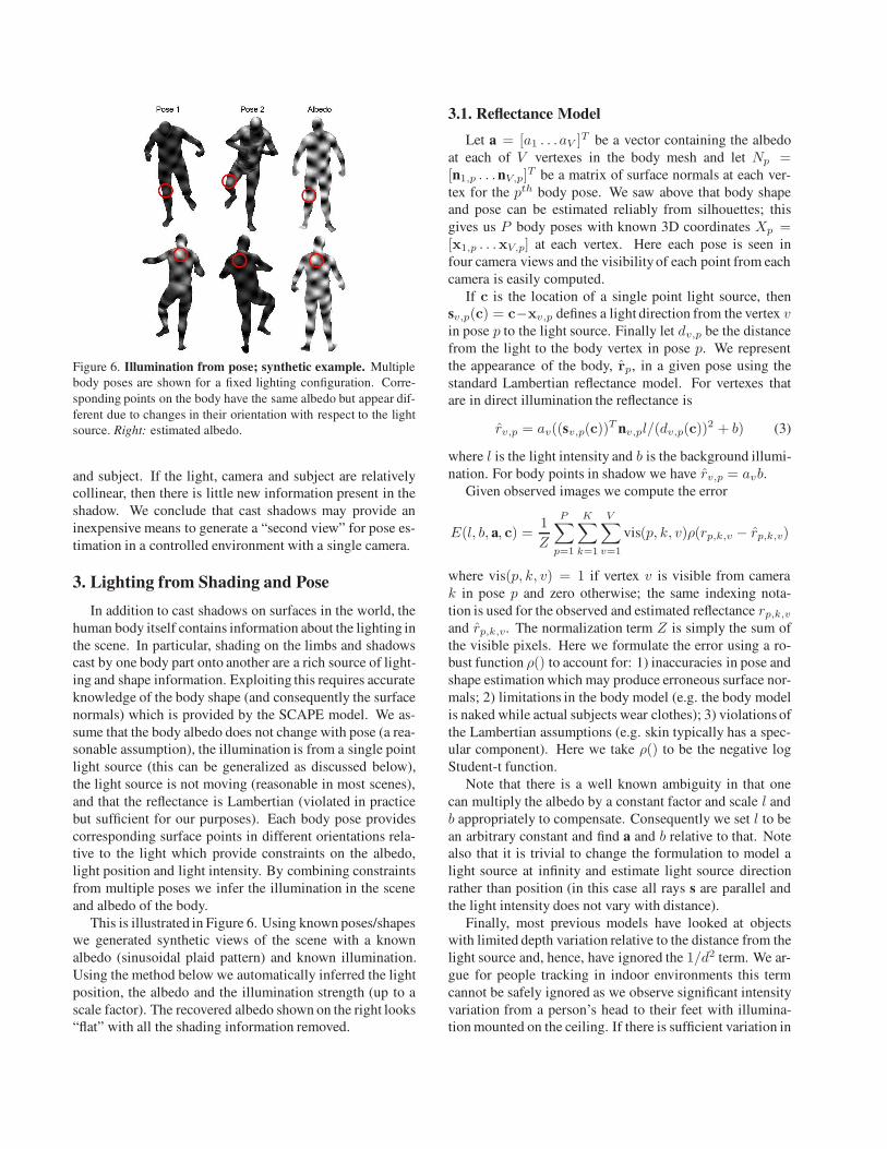
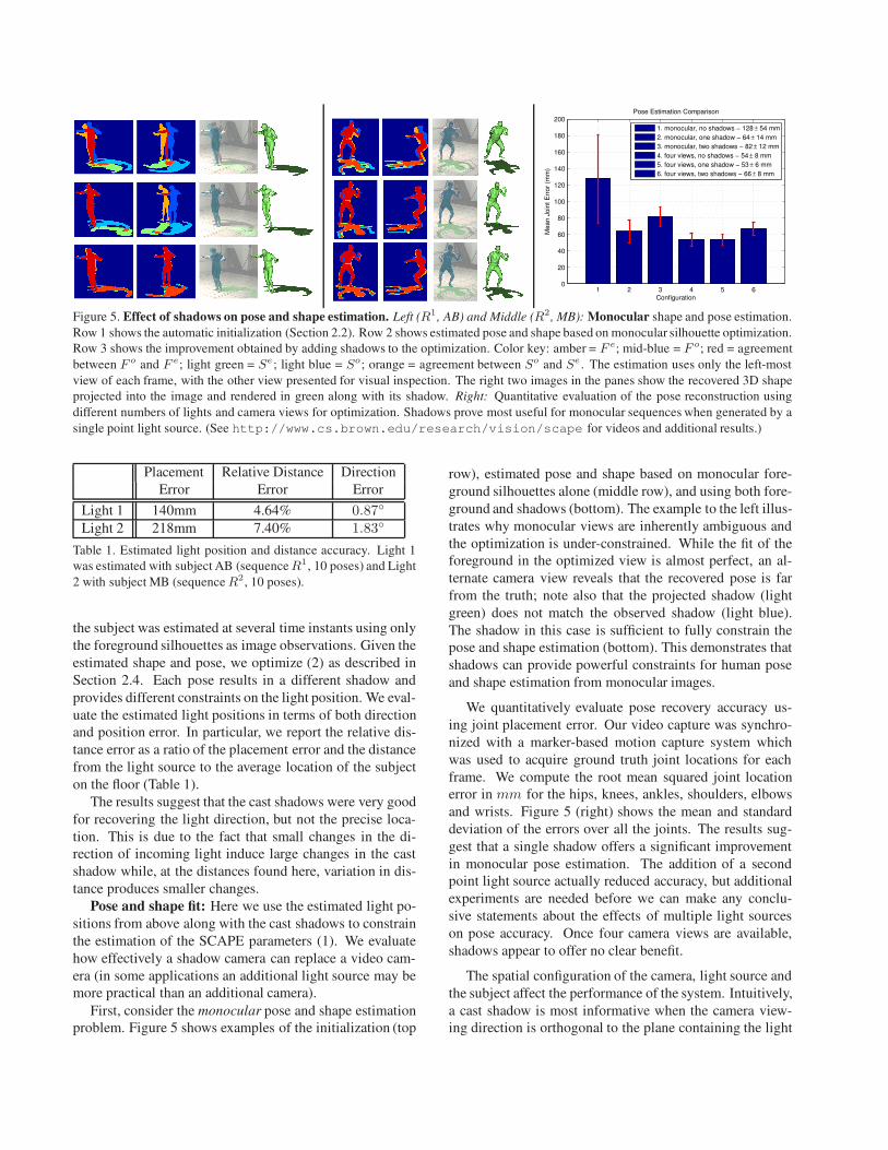
Figure 6. Illumination from pose; synthetic example. Multiple
body poses are shown for a fixed lighting configuration. Corre-
sponding points on the body have the same albedo but appear dif-
ferent due to changes in their orientation with respect to the light
source. Right: estimated albedo.
and subject. If the light, camera and subject are relatively
collinear, then there is little new information present in the
shadow. We conclude that cast shadows may provide an
inexpensive means to generate a “second view” for pose es-
timation in a controlled environment with a single camera.
3. Lighting from Shading and Pose
In addition to cast shadows on surfaces in the world, the
human body itself contains information about the lighting in
the scene. In particular, shading on the limbs and shadows
cast by one body part onto another are a rich source of light-
ing and shape information. Exploiting this requires accurate
knowledge of the body shape (and consequently the surface
normals) which is provided by the SCAPE model. We as-
sume that the body albedo does not change with pose (a rea-
sonable assumption), the illumination is from a single point
light source (this can be generalized as discussed below),
the light source is not moving (reasonable in most scenes),
and that the reflectance is Lambertian (violated in practice
but sufficient for our purposes). Each body pose provides
corresponding surface points in different orientations rela-
tive to the light which provide constraints on the albedo,
light position and light intensity. By combining constraints
from multiple poses we infer the illumination in the scene
and albedo of the body.
This is illustrated in Figure 6. Using known poses/shapes
we generated synthetic views of the scene with a known
albedo (sinusoidal plaid pattern) and known illumination.
Using the method below we automatically inferred the light
position, the albedo and the illumination strength (up to a
scale factor). The recovered albedo shown on the right looks
“flat” with all the shading information removed.
3.1. Reflectance Model
Let a = [a1 . . . aV ]T be a vector containing the albedo
at each of V vertexes in the body mesh and let Np =[n1,p . . .nV,p]
T be a matrix of surface normals at each ver-
tex for the pth body pose. We saw above that body shape
and pose can be estimated reliably from silhouettes; this
gives us P body poses with known 3D coordinates Xp =[x1,p . . .xV,p] at each vertex. Here each pose is seen in
four camera views and the visibility of each point from each
camera is easily computed.
If c is the location of a single point light source, then
sv,p(c) = c−xv,p defines a light direction from the vertex vin pose p to the light source. Finally let dv,p be the distance
from the light to the body vertex in pose p. We represent
the appearance of the body, rp, in a given pose using the
standard Lambertian reflectance model. For vertexes that
are in direct illumination the reflectance is
rv,p = av((sv,p(c))T nv,pl/(dv,p(c))
2 + b) (3)
where l is the light intensity and b is the background illumi-
nation. For body points in shadow we have rv,p = avb.
Given observed images we compute the error
E(l, b, a, c) =1
Z
P∑
p=1
K∑
k=1
V∑
v=1
vis(p, k, v)ρ(rp,k,v − rp,k,v)
where vis(p, k, v) = 1 if vertex v is visible from camera
k in pose p and zero otherwise; the same indexing nota-
tion is used for the observed and estimated reflectance rp,k,v
and rp,k,v. The normalization term Z is simply the sum of
the visible pixels. Here we formulate the error using a ro-
bust function ρ() to account for: 1) inaccuracies in pose and
shape estimation which may produce erroneous surface nor-
mals; 2) limitations in the body model (e.g. the body model
is naked while actual subjects wear clothes); 3) violations of
the Lambertian assumptions (e.g. skin typically has a spec-
ular component). Here we take ρ() to be the negative log
Student-t function.
Note that there is a well known ambiguity in that one
can multiply the albedo by a constant factor and scale l and
b appropriately to compensate. Consequently we set l to be
an arbitrary constant and find a and b relative to that. Note
also that it is trivial to change the formulation to model a
light source at infinity and estimate light source direction
rather than position (in this case all rays s are parallel and
the light intensity does not vary with distance).
Finally, most previous models have looked at objects
with limited depth variation relative to the distance from the
light source and, hence, have ignored the 1/d2 term. We ar-
gue for people tracking in indoor environments this term
cannot be safely ignored as we observe significant intensity
variation from a person’s head to their feet with illumina-
tion mounted on the ceiling. If there is sufficient variation in
Figure 7. Estimated light position; synthetic example. Black
dots represent the course initializations of the light. Red stars are
the initial locations with lowest error. Green are the the result of
optimization starting with the red stars. Blue is the ground truth.
depth of points across poses, this quadratic fall-off of light
intensity helps constrain the distance of the light source.
3.2. Optimization
Minimizing E(l, b, a, c) takes place in two stages. First a
coarse initialization search is performed. Assuming a single
point light source we discretize the space as in Section 2.4
(see Figure 7). Given each hypothesized light position we
solve for a and b (recall l is fixed) using coordinate descent.
The background illumination is initialized to b = 0 and the
albedo to a constant value over the entire body. The five
light positions with the lowest residual error are selected as
initial starting locations.
The algorithm then optimizes over the all the param-
eters including the light source location, c, using coordi-
nate descent; note we enforce positivity constraints on the
albedo and background illumination during optimization.
Convergence is determined when the change in the resid-
ual E(l, b, a, c) is less than a threshold for five iterations.
The gradients with respect to the parameters are all straight-
forward except for those related to light position. Changes
in light position change which vertexes are directly illumi-
nated; computing the gradient with respect to these changes
cannot be done in closed form and approximating it is too
computationally costly since it involves multiple visibility
computations. Consequently, we approximate the gradient
with respect to c by simply ignoring these changes in illu-
minated vertexes. Still, at each iteration of the descent, the
visibility with respect to the light must be computed and
this is the most computationally expensive part of the al-
gorithm. Current visibility computations are performed in
Matlab and take about one second per view; this could be
reduced with graphics hardware.
3.3. Albedo and Lighting Results
We evaluate the method using a synthetic sequence (S1)
where all parameters are known and two real sequences
(R1, 83 poses and R2, 23 poses). S1 was constructed using
Figure 8. Estimated albedos for two different subjects and light
positions.
Figure 9. Albedo constancy. Given known lighting, we undo its
effect in images. Several views of the body are shown viewed
from different cameras in different poses. In each pair, the left
shows the visible pixel luminance values while the right shows
these values “corrected” to remove lighting. Note that the effects
of illumination are greatly reduced.
the same body shapes and lighting as R1 but the observa-
tions were generated using the model (3) and a synthetic
albedo. To recover the albedo in the real sequences, we first
converted the input images to a single luminance channel
(sum of RGB values) and excluded pixels that were satu-
rated (pixels values in the top 10% for a given frame).
Figure 7 shows the recovered light position for S1. De-
spite having a unique minimum, we found the distance of
the light source was weakly constrained in practice (lying
along a line). The position was fairly accurately recov-
ered with the best estimate being 56.3mm (1.86%) from
the truth. The estimated albedo accounted for for 98% of
the variance in the true albedo.
For the real sequences the camera positions were consis-
tently biased below the true position. The error in position
was 506.2mm (16.7%) for R1 and 412.7mm (12.67%) for
R2. Here we posit that a non-linear camera response near
saturated regions caused the bias. The recovered albedos
for the two sequences are shown in Figure 8. In both cases,
the estimated albedo appropriately lacks most of the shad-
ing information present in the input data.
3.4. Albedo Constancy
Changes in orientation with respect to the light source
cause changes in luminance; these violate the common as-
sumption of brightness constancy used in many tracking
frameworks. In human tracking, these illumination ef-
fects can be significant [12]. Given estimated light posi-
tion (or direction), light intensity, and background illumina-
Brightness deviation Albedo deviation
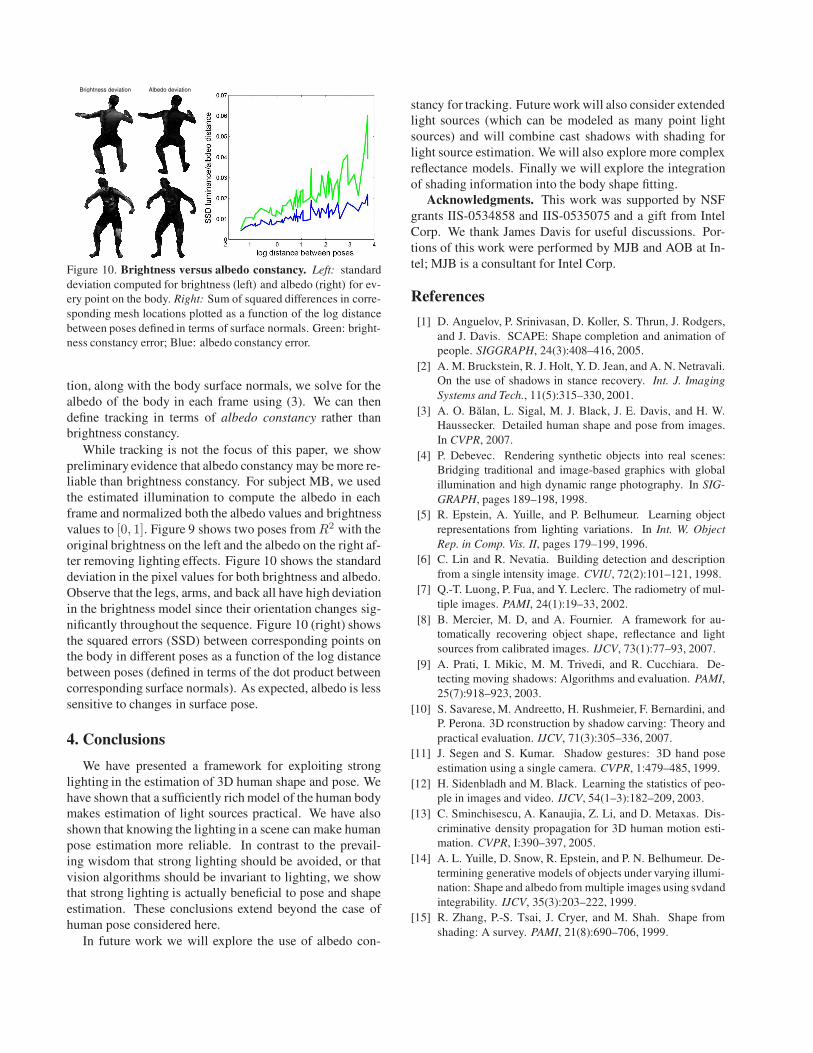
Figure 10. Brightness versus albedo constancy. Left: standard
deviation computed for brightness (left) and albedo (right) for ev-
ery point on the body. Right: Sum of squared differences in corre-
sponding mesh locations plotted as a function of the log distance
between poses defined in terms of surface normals. Green: bright-
ness constancy error; Blue: albedo constancy error.
tion, along with the body surface normals, we solve for the
albedo of the body in each frame using (3). We can then
define tracking in terms of albedo constancy rather than
brightness constancy.
While tracking is not the focus of this paper, we show
preliminary evidence that albedo constancy may be more re-
liable than brightness constancy. For subject MB, we used
the estimated illumination to compute the albedo in each
frame and normalized both the albedo values and brightness
values to [0, 1]. Figure 9 shows two poses from R2 with the
original brightness on the left and the albedo on the right af-
ter removing lighting effects. Figure 10 shows the standard
deviation in the pixel values for both brightness and albedo.
Observe that the legs, arms, and back all have high deviation
in the brightness model since their orientation changes sig-
nificantly throughout the sequence. Figure 10 (right) shows
the squared errors (SSD) between corresponding points on
the body in different poses as a function of the log distance
between poses (defined in terms of the dot product between
corresponding surface normals). As expected, albedo is less
sensitive to changes in surface pose.
4. Conclusions
We have presented a framework for exploiting strong
lighting in the estimation of 3D human shape and pose. We
have shown that a sufficiently rich model of the human body
makes estimation of light sources practical. We have also
shown that knowing the lighting in a scene can make human
pose estimation more reliable. In contrast to the prevail-
ing wisdom that strong lighting should be avoided, or that
vision algorithms should be invariant to lighting, we show
that strong lighting is actually beneficial to pose and shape
estimation. These conclusions extend beyond the case of
human pose considered here.
In future work we will explore the use of albedo con-
stancy for tracking. Future work will also consider extended
light sources (which can be modeled as many point light
sources) and will combine cast shadows with shading for
light source estimation. We will also explore more complex
reflectance models. Finally we will explore the integration
of shading information into the body shape fitting.
Acknowledgments. This work was supported by NSF
grants IIS-0534858 and IIS-0535075 and a gift from Intel
Corp. We thank James Davis for useful discussions. Por-
tions of this work were performed by MJB and AOB at In-
tel; MJB is a consultant for Intel Corp.
References
[1] D. Anguelov, P. Srinivasan, D. Koller, S. Thrun, J. Rodgers,
and J. Davis. SCAPE: Shape completion and animation of
people. SIGGRAPH, 24(3):408–416, 2005.
[2] A. M. Bruckstein, R. J. Holt, Y. D. Jean, and A. N. Netravali.
On the use of shadows in stance recovery. Int. J. Imaging
Systems and Tech., 11(5):315–330, 2001.
[3] A. O. Balan, L. Sigal, M. J. Black, J. E. Davis, and H. W.
Haussecker. Detailed human shape and pose from images.
In CVPR, 2007.
[4] P. Debevec. Rendering synthetic objects into real scenes:
Bridging traditional and image-based graphics with global
illumination and high dynamic range photography. In SIG-
GRAPH, pages 189–198, 1998.
[5] R. Epstein, A. Yuille, and P. Belhumeur. Learning object
representations from lighting variations. In Int. W. Object
Rep. in Comp. Vis. II, pages 179–199, 1996.
[6] C. Lin and R. Nevatia. Building detection and description
from a single intensity image. CVIU, 72(2):101–121, 1998.
[7] Q.-T. Luong, P. Fua, and Y. Leclerc. The radiometry of mul-
tiple images. PAMI, 24(1):19–33, 2002.
[8] B. Mercier, M. D, and A. Fournier. A framework for au-
tomatically recovering object shape, reflectance and light
sources from calibrated images. IJCV, 73(1):77–93, 2007.
[9] A. Prati, I. Mikic, M. M. Trivedi, and R. Cucchiara. De-
tecting moving shadows: Algorithms and evaluation. PAMI,
25(7):918–923, 2003.
[10] S. Savarese, M. Andreetto, H. Rushmeier, F. Bernardini, and
P. Perona. 3D rconstruction by shadow carving: Theory and
practical evaluation. IJCV, 71(3):305–336, 2007.
[11] J. Segen and S. Kumar. Shadow gestures: 3D hand pose
estimation using a single camera. CVPR, 1:479–485, 1999.
[12] H. Sidenbladh and M. Black. Learning the statistics of peo-
ple in images and video. IJCV, 54(1–3):182–209, 2003.
[13] C. Sminchisescu, A. Kanaujia, Z. Li, and D. Metaxas. Dis-
criminative density propagation for 3D human motion esti-
mation. CVPR, I:390–397, 2005.
[14] A. L. Yuille, D. Snow, R. Epstein, and P. N. Belhumeur. De-
termining generative models of objects under varying illumi-
nation: Shape and albedo from multiple images using svdand
integrability. IJCV, 35(3):203–222, 1999.
[15] R. Zhang, P.-S. Tsai, J. Cryer, and M. Shah. Shape from
shading: A survey. PAMI, 21(8):690–706, 1999.