Embed Size (px)
Citation preview
(English) DM-ST0001-05
Dealer's Manual
Shifting lever
MTB
RAPIDFIRE PlusST-M4000ST-M4050ST-T4000ST-T3000ST-M370
EZ-FIRE PlusST-EF65ST-EF51ST-EF51-AST-TX800ST-EF41ST-EF40
ROAD
TiagraST-4600ST-4603
SORAST-3500ST-3503
SHIMANO ClarisST-2400ST-2403
SHIMANO 2300ST-2300ST-2303
TourneyST-A070ST-A073
Non-SeriesST-R460ST-R350ST-R353ST-R240ST-R243
2
IMPORTANT NOTICE
• This dealer's manual is intended primarily for use by professional bicycle mechanics.Users who are not professionally trained for bicycle assembly should not attempt to install the components themselves using the dealer's manuals.If any part of the information on the manual is unclear to you, do not proceed with the installation. Instead, contact your place of purchase or a local bicycle dealer for their assistance.
• Make sure to read all instruction manuals included with the product.
• Do not disassemble or modify the product other than as stated in the information contained in this dealer's manual.
• All dealer's manuals and instruction manuals can be viewed on-line on our website (http://si.shimano.com).
• Please observe the appropriate rules and regulations of the country, state or region in which you conduct your business as a dealer.
For safety, be sure to read this dealer's manual thoroughly before use, and follow it for correct use.
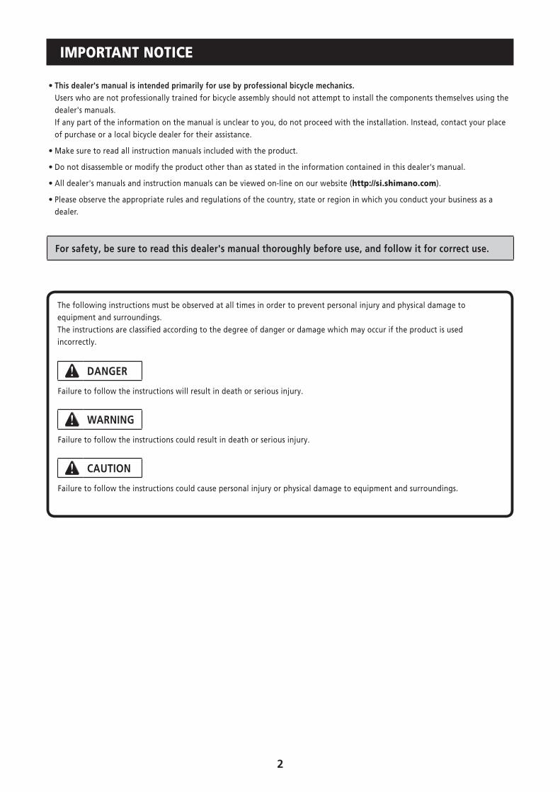
The following instructions must be observed at all times in order to prevent personal injury and physical damage to equipment and surroundings.The instructions are classified according to the degree of danger or damage which may occur if the product is used incorrectly.
DANGER
Failure to follow the instructions will result in death or serious injury.
WARNING
Failure to follow the instructions could result in death or serious injury.
CAUTION
Failure to follow the instructions could cause personal injury or physical damage to equipment and surroundings.

3
TO ENSURE SAFETY
WARNING
• When installing components, be sure to follow the instructions that are given in the instruction manuals. It is recommended to use genuine Shimano parts only. If parts such as bolts and nuts become loose or damaged, the bicycle may suddenly fall over, which may cause serious injury. In addition, if adjustments are not carried out correctly, problems may occur, and the bicycle may suddenly fall over, which may cause serious injury.
• Be sure to wear safety glasses or goggles to protect your eyes while performing maintenance tasks such as replacing parts.
• After reading the dealer's manual thoroughly, keep it in a safe place for later reference.
Be sure to also inform users of the following:
• The ST-EF65/ST-EF51/ST-EF51-A (4-finger brake levers) brake levers are equipped with a mechanism to make them compatible with V-BRAKE brakes, which contain a power modulator, cantilever and roller brakes.
If the incorrect mode is selected it may cause either excessive or insufficient braking force to occur, which could result in dangerous accidents. Be sure to select the mode in accordance with the instructions given in the table below.
Mode position Applicable brake
C R
V
V
C R
V
V
C R
C/R position
C : Mode position for compatibility with cantilever brakes
R : Mode position for compatibility with roller brakes
• Cantilever brakes
• Roller brakes
C R
V
V
C R
V
V position
V : Mode position for compatibility with V-BRAKE brakes
with power modulator
• V-BRAKE brakes (BR-M422) with SM-PM40 power modulator attached
Use the brake levers with mode switching mechanism in the combinations given above.
4
• Each bicycle may handle differently depending on the product. Therefore, it is important to completely understand and get used to the operation of your bicycle's brake system (including brake lever pressure and bicycle control characteristics). Improper use of your bicycle's brake system may result in a loss of control or a fall, which could lead to severe injury. For proper operation please consult a professional bicycle dealer, or read the owner’s manual. It is important to ride your bicycle and practice braking operation and other basic features, etc.
• If the front brake is applied too strongly, the wheel may lock and the bicycle may fall forward, and serious injury may result.
• Always make sure that the front and rear brakes are working correctly before riding the bicycle.
• The required braking distance will be longer during wet weather. Reduce your speed and apply the brakes early and gently.
• If the road surface is wet, the tires will skid more easily. If the tires skid, you may fall off the bicycle. To avoid this, reduce your speed and apply the brakes early and gently.
NOTE
Be sure to also inform users of the following:
• Be sure to keep turning the crank during gear shifting.
• Read the dealer's manuals for the front derailleur, rear derailleur, and brake.
• Products are not guaranteed against natural wear and deterioration from normal use and aging.
• For maximum performance we highly recommend Shimano lubricants and maintenance products.
For Installation to the Bicycle, and Maintenance:
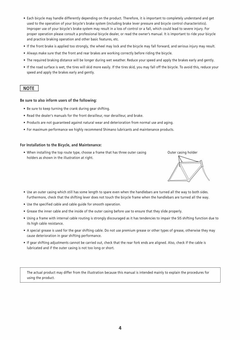
• When installing the top route type, choose a frame that has three outer casing holders as shown in the illustration at right.
Outer casing holder
• Use an outer casing which still has some length to spare even when the handlebars are turned all the way to both sides. Furthermore, check that the shifting lever does not touch the bicycle frame when the handlebars are turned all the way.
• Use the specified cable and cable guide for smooth operation.
• Grease the inner cable and the inside of the outer casing before use to ensure that they slide properly.
• Using a frame with internal cable routing is strongly discouraged as it has tendencies to impair the SIS shifting function due to its high cable resistance.
• A special grease is used for the gear shifting cable. Do not use premium grease or other types of grease, otherwise they may cause deterioration in gear shifting performance.
• If gear shifting adjustments cannot be carried out, check that the rear fork ends are aligned. Also, check if the cable is lubricated and if the outer casing is not too long or short.
The actual product may differ from the illustration because this manual is intended mainly to explain the procedures for using the product.

5
INSTALLATION
MTB
� Installation to the handlebarThe tools and tightening torque vary depending on the product. Tighten with a tightening torque that matches the tool size.
* Use a handlebar grip with a maximum outer diameter of ɸ 32 mm.
5 mm Allen key
Tightening torque: 6 - 8 N·m {53 - 69 in. lbs.}
3 mm Allen key
Tightening torque: 4 N·m {35 in. lbs.}
< ST-TX800, ST-EF41 >3 mm Allen key
Tightening torque: 3.5 - 4.5 N·m {31 - 39 in. lbs.}
� Installation of the brake cable* Install it as shown in the figure.
1
2
3

6
ROAD
� Installation to the handlebar
Drop handlebar type
Secure the assembly with the clamp bolt on the outside of the bracket.Pull the bracket cover back and use a 5 mm Allen key to tighten the bolt.
Tightening torque: 6 - 8 N·m {53 - 69 in. lbs.}
Bracket cover
Clamp bolt
5 mm Allen key
Flat handlebar type
Use a handlebar grip with a maximum outer diameter of ɸ 32 mm.
Tightening torque: 6 - 8 N·m {53 - 69 in. lbs.}
4 mm Allen key

7
� Installation of the brake cable
ROAD
Cable used
Inner cable SLR outer casing
ɸ 1.6 mm ɸ 5 mm
* Use a cable which still has some length to spare even when the handlebars are turned all the way to both sides.* For information on how to install the brake cable, refer to brake dealer's manual.
1. Tilt the lever in (as when shifting) to make it easier to pass the cable through the cable hook.
Pull
Tilt
Note: After lever (B) is pushed once or twice, the front lever can be tilted inwards.
Lever (B) Lever (B)
2. Pass the inner cable through.
Cable hook
Inner cable
Make sure that the inner end is firmly set in the cable hook.
Cable hook
Inner end
Note: Do not wipe off the grease on the inner cable.Do not let dust adhere on the inner cable.
3. Finally, wrap the handlebar with the handlebar tape.

8
MTB
* Install it as shown in the figure.
1
2
3
� Installing the shifting cable
Cable used
(2)
(1)
Wire lead
Inner cable
(Stainless steel)
ST-4600 / ST-4603 / ST-3500 / ST-3503 ST-2400 / ST-2403 / ST-R460 / ST-R350 / ST-R353
SP41 sealed outer casing (1) SP41 outer casing (2)
ɸ 1.2 mm
SEALEDSP41
ɸ 4 mm
SP41
ɸ 4 mm
ST-M4050 / ST-2300 / ST-2303
SP40 sealed outer casing (1) SP40 outer casing (2)
SEALEDSP40
ɸ 4 mm
SP40
ɸ 4 mm
ST-A070 / ST-A073
SIS40 outer casing (1)(2)
SIS40
ɸ 4 mm
9
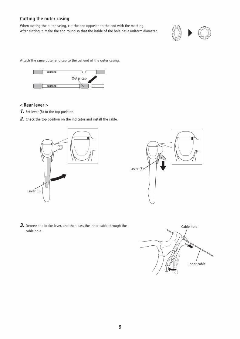
Cutting the outer casingWhen cutting the outer casing, cut the end opposite to the end with the marking.After cutting it, make the end round so that the inside of the hole has a uniform diameter.
Attach the same outer end cap to the cut end of the outer casing.
Outer cap
< Rear lever >1. Set lever (B) to the top position.
2. Check the top position on the indicator and install the cable.
Lever (B)
Lever (B)
3. Depress the brake lever, and then pass the inner cable through the cable hole.
Cable hole
Inner cable

10
4. Run the inner cable through the outer casing.
2
Cable hole
Inner cable
Outer casing
If the cable hook does not align with the shifting cable hole, press lever (B) again until it does, and then install the cable.
Cable hook
Confirm: Make sure that the inner end is firmly set in the cable hook.
Inner end
Cable hook
11
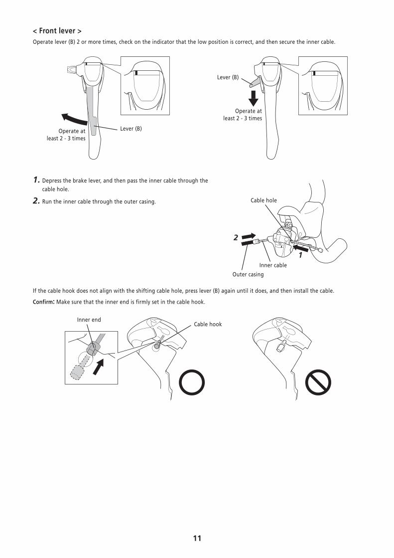
< Front lever >Operate lever (B) 2 or more times, check on the indicator that the low position is correct, and then secure the inner cable.
Lever (B)
Operate at least 2 - 3 times
Lever (B)Operate at least 2 - 3 times
1. Depress the brake lever, and then pass the inner cable through the cable hole.
2. Run the inner cable through the outer casing.
1
2
Cable hole
Inner cable
Outer casing
If the cable hook does not align with the shifting cable hole, press lever (B) again until it does, and then install the cable.
Confirm: Make sure that the inner end is firmly set in the cable hook.
Cable hookInner end
12
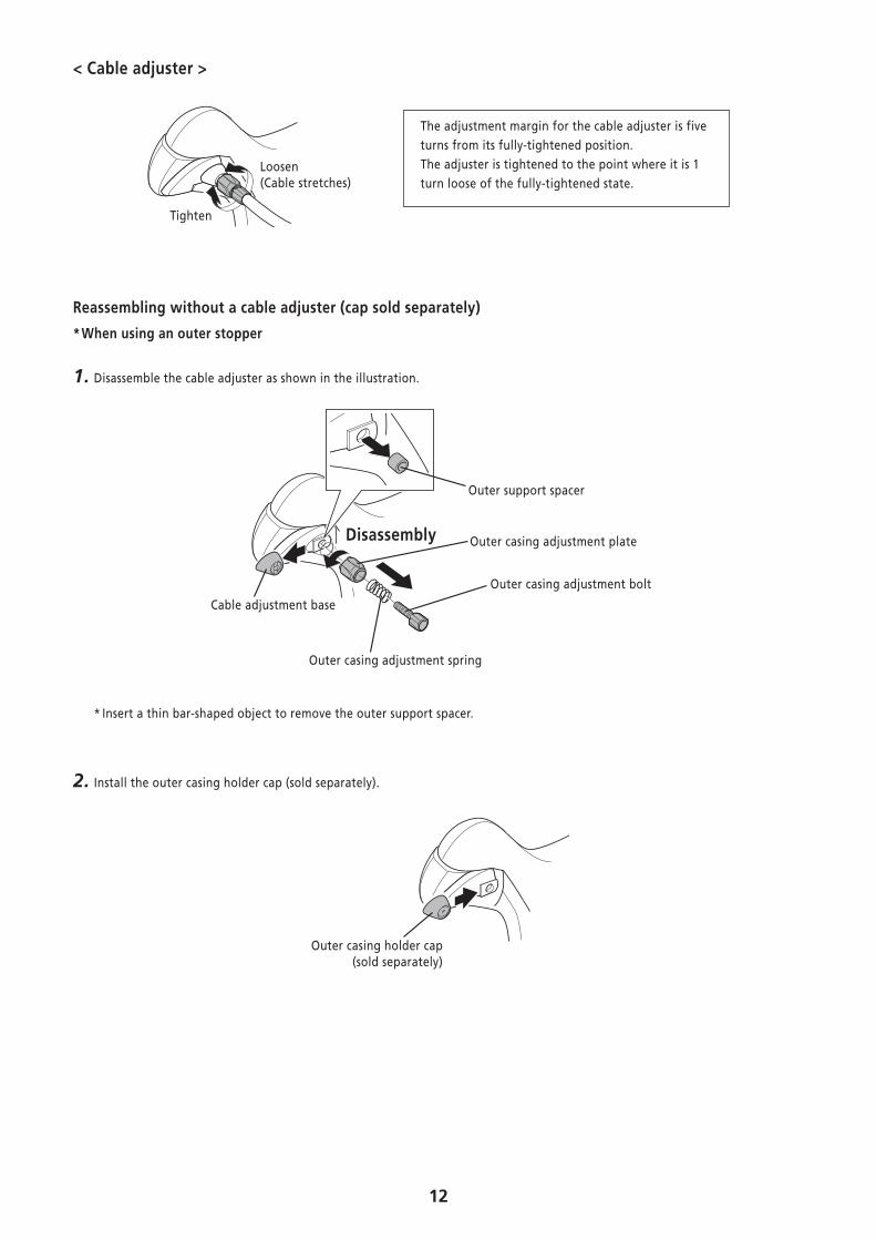
< Cable adjuster >
Loosen(Cable stretches)
Tighten
The adjustment margin for the cable adjuster is five turns from its fully-tightened position.The adjuster is tightened to the point where it is 1 turn loose of the fully-tightened state.
Reassembling without a cable adjuster (cap sold separately)
* When using an outer stopper
1. Disassemble the cable adjuster as shown in the illustration.
Outer support spacer
Outer casing adjustment plate
Outer casing adjustment bolt
Outer casing adjustment spring
Disassembly
Cable adjustment base
* Insert a thin bar-shaped object to remove the outer support spacer.
2. Install the outer casing holder cap (sold separately).
Outer casing holder cap (sold separately)

13
� Installing the outer stopper* Install an outer stopper as needed. (Not included with the product)
1. Install the outer stopper to the down tube.
Outer stopper
Fixing bolt
Installation bolt
3 mm Allen key
Brazed-on boss (M5)
Tightening torque: 1.5 - 2 N·m {14 - 17 in. lbs.}
Note: Install after the adjustment bolt is tightened. The adjustment range for the adjustment bolt is six full turns.
2. Pass the inner cable through, and set the outer casing.* Use an outer casing which still has some length to spare even
when the handlebars are turned all the way to both sides.
Confirm: Make sure the outer casing is firmly set in the outer stopper. Outer stopper
Inner cable
Outer casing
14
ADJUSTMENT
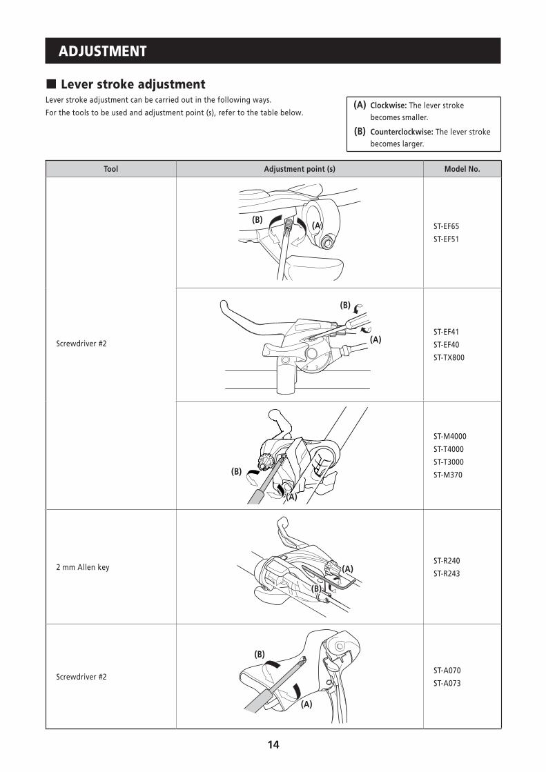
� Lever stroke adjustmentLever stroke adjustment can be carried out in the following ways.
For the tools to be used and adjustment point (s), refer to the table below.(A) Clockwise: The lever stroke
becomes smaller.
(B) Counterclockwise: The lever stroke becomes larger.
Tool Adjustment point (s) Model No.
Screwdriver #2
(A)(B)
ST-EF65
ST-EF51
(A)
(B)
ST-EF41
ST-EF40
ST-TX800
(A)
(B)
ST-M4000
ST-T4000
ST-T3000
ST-M370
2 mm Allen key (A)
(B)
ST-R240
ST-R243
Screwdriver #2
(A)
(B)
ST-A070
ST-A073

15
When using the reach adjustment block (Pad spacer)
Note:When installing the 8-degree reach adjustment block, use an anatomic-type handlebar. If a round-type handlebar is used, the cable stroke may become too short and this can result in insufficient braking force.
Anatomic type Round type
< ST-4600 / ST-4603 / ST-3500 / ST-3503 / ST-2400 / ST-2403 / ST-R460 / ST-R350 / ST-R353 >
Pad spacers (A)
7.5 mm
4°
Initial condition: 4˚
Bump rubber
Pad spacers (A)
Pad spacers (A) + (B)
14 mm
8°
Pad spacers (B)
Pad spacers (A)
To increase the lever stroke
Remove the pad spacer (A) and install the bump rubber.
To decrease the lever stroke
Insert pad spacer (B) as far as it will go and so that the protrusions fit into the holes in pad spacer (A).
* Apply a small amount of grease to the protrusions when installing the pad spacer and the bump rubber.

16
< ST-2300 / ST-2303 >
To reduce the reach, remove the bump rubber and replace it with the accessory pad spacer (two available types: 4° and 8°).
14 mm7.5 mm
8°
Pad spacer
4°
Replacement method
1. Remove the bump rubber.
2. Apply a thin layer of grease to the two protrusions on the pad spacer.
3. Press-fit the pad spacer so that the protrusion go as far in as possible.
Bump rubber Pad spacer
� Adjusting the inner cable
When the cable adjuster is provided The adjustment margin for the cable adjuster is five turns from its fully-tightened position.The adjuster is tightened to the point where it is 1 turn loose of the fully-tightened state. Loosen
(Cable stretches)
Tighten
17
MAINTENANCE
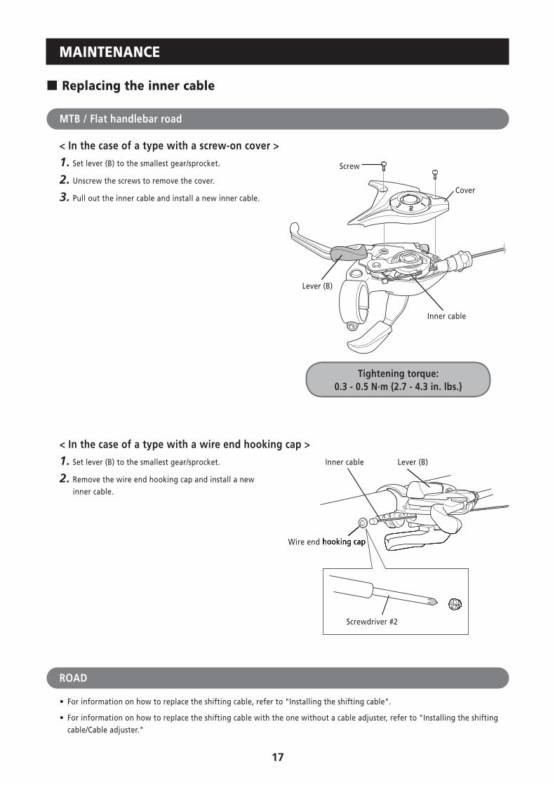
� Replacing the inner cable
MTB / Flat handlebar road
< In the case of a type with a screw-on cover >
1. Set lever (B) to the smallest gear/sprocket.
2. Unscrew the screws to remove the cover.
3. Pull out the inner cable and install a new inner cable.
Tightening torque:0.3 - 0.5 N·m {2.7 - 4.3 in. lbs.}
Screw
Cover
Inner cable
Lever (B)
< In the case of a type with a wire end hooking cap >
1. Set lever (B) to the smallest gear/sprocket.
2. Remove the wire end hooking cap and install a new inner cable.
Wire end hooking cap
Inner cable Lever (B)
Wire end hooking cap
Screwdriver #2
ROAD
• For information on how to replace the shifting cable, refer to "Installing the shifting cable".
• For information on how to replace the shifting cable with the one without a cable adjuster, refer to "Installing the shifting cable/Cable adjuster."

18
� Bracket and lever disassembly* The illustration shows the right-hand lever.
< ST-4600 / ST-4603 / ST-3500 / ST-3503 / ST-2400 / ST-2403 / ST-R460 / ST-R350 / ST-R353 >
1. First use the Shimano original tool (sold separately) to remove the E-ring. Use part (B) of the Shimano original tool (2) to align the E-ring with the direction of removal. Next, set part (A) against the E-ring and remove the E-ring.* Tourney is not equipped with an E-ring.
E-ring removal direction
Y6RT66000 Y6RT68000
(2)(1)
(A)
(B)
Shimano original E-ring removal tool
CAUTION
When removing the E-ring, it may suddenly spring out, make sure there are no persons or objects around before removing it.
E-ring
2. Insert an Allen key or similar tool into the lever axle hole, tap it gently with a plastic hammer to push out the lever axle, which disassembles it into the bracket body and the lever body.
Bracket body
Lever axle
Lever body
Note: Always be sure to remove the lever axle in this direction. If it is removed in the opposite direction, it may damage the bracket body.
19
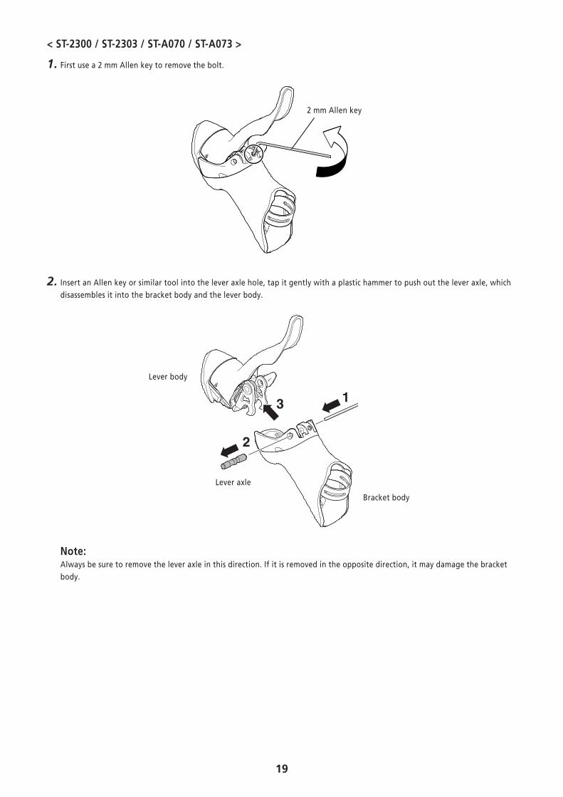
< ST-2300 / ST-2303 / ST-A070 / ST-A073 >
1. First use a 2 mm Allen key to remove the bolt.
2 mm Allen key
2. Insert an Allen key or similar tool into the lever axle hole, tap it gently with a plastic hammer to push out the lever axle, which disassembles it into the bracket body and the lever body.
Bracket body
Lever axle
Lever body
Note: Always be sure to remove the lever axle in this direction. If it is removed in the opposite direction, it may damage the bracket body.

20
� Replacing the return spring
< ST-3500 / ST-3503 / ST-2400 / ST-2403 / ST-R350 / ST-R353 >
1. With the spacer fitted in the return spring, push the tip of the return spring into the hole in the bearing member, and press in the shaft bushing.* Note that the left and right return springs are different.
Return spring
Bearing member
Shaft bushing
Set the end of the spring in the hole in the bearing member.
Hole
Spacer
< ST-2300 / ST-2303 >
1. Set the return spring on the hole in the bearing member of the lever body.* Note that the left and right return springs are different.
Return spring
Bearing member
Set the end of the spring in the hole in the bearing member.
Hole

21
� Assembling the bracket body and lever body
< ST-4600 / ST-4603 / ST-R460 >
1.
Return spring
Notch
2. Align the stud holes, and then set the Shimano original tool (1) in the position shown in the illustration to press-fit the lever axle.
• The correct direction for the lever axle is for the E-ring groove to face up.
• Check that the surface of the bracket body is flat so the E-ring of the lever axle can fit into the groove properly.
E-ring groove
Shimano original E-ring removal tool (1):Y6RT66000
3. Remove the Shimano original tool (1), and then use the Shimano original tool (2) to install the E-ring.
Shimano original E-ring removal tool (2):Y6RT68000

22
< ST-3500 / ST-3503 / ST-2400 / ST-2403 / ST-R350 / ST-R353 >
1. Set the Shimano original installation tool for the return spring.
Shimano original installation tool for the return spring (TL-ST03)
2. Align the stud holes, and then set the Shimano original tool (1) in the position shown in the illustration to press-fit the lever axle.
• The correct direction for the lever axle is for the E-ring groove to face up.
• Check that the surface of the bracket body is flat so the E-ring of the lever axle can fit into the groove properly.
E-ring groove
Shimano original E-ring removal tool (1):Y6RT66000
3. Remove the Shimano original tool (1), and then use the Shimano original tool (2) to install the E-ring.
Shimano original E-ring removal tool (2):Y6RT68000
4. Remove the Shimano original installation tool for the return spring with pliers.
5. Finally, check that brake operation is normal and the return spring functions properly.
Shimano original installation tool for
the return spring

23
< ST-2300 / ST-2303 / ST-A070 / ST-A073 >
1. Set the Shimano original installation tool for the return spring.
Shimano original installation tool for the return spring (TL-ST03)
2. Align the stud holes, and then press-fit the lever axle in the position shown in the illustration.
Lever axle
The correct position is for the round hollow on the lever axle to be aligned with the lever fixing screw.
1 Press-fit
2 Fixed by a lever fixing screw
2 mm Allen key
Lever fixingscrew
Tightening torque: 1 - 2 N·m {9 - 17 in. lbs.}
3. Remove the Shimano original installation tool for the return spring with pliers.
4. Finally, check that brake operation is normal and the return spring functions properly. Shimano original
installation tool for the return spring

24
� Replacing the bracket cover
The tabs on the bracket cover each fit to a matching slot on the bracket.
• Wipe a little rubbing alcohol inside the bracket cover to make installation easier.
Note the markings:
R: for right L: for left

Please note: specifications are subject to change for improvement without notice. (English) © Feb. 2015 by Shimano Inc. HTR


![No Model VIN 1 (DM) SANTAFE [DM] KMHSU81BSCU000212 2 … Engine YF and D… · 37 (dm) santafe [dm] kmhst81bsdu023920 38 (dm) santafe [dm] kmhst81bsdu023926 39 (dm) santafe [dm] kmhst81bsdu023930](https://img.pdfslide.us/doc/110x75/6017564e29e54a6dde7ebe6b/no-model-vin-1-dm-santafe-dm-kmhsu81bscu000212-2-engine-yf-and-d-37-dm-santafe.jpg)