Embed Size (px)
DESCRIPTION
Studio Air
Citation preview
STUDIO AIR
2015, SEMESTER 1, Sonya Jia Jia Shen636970
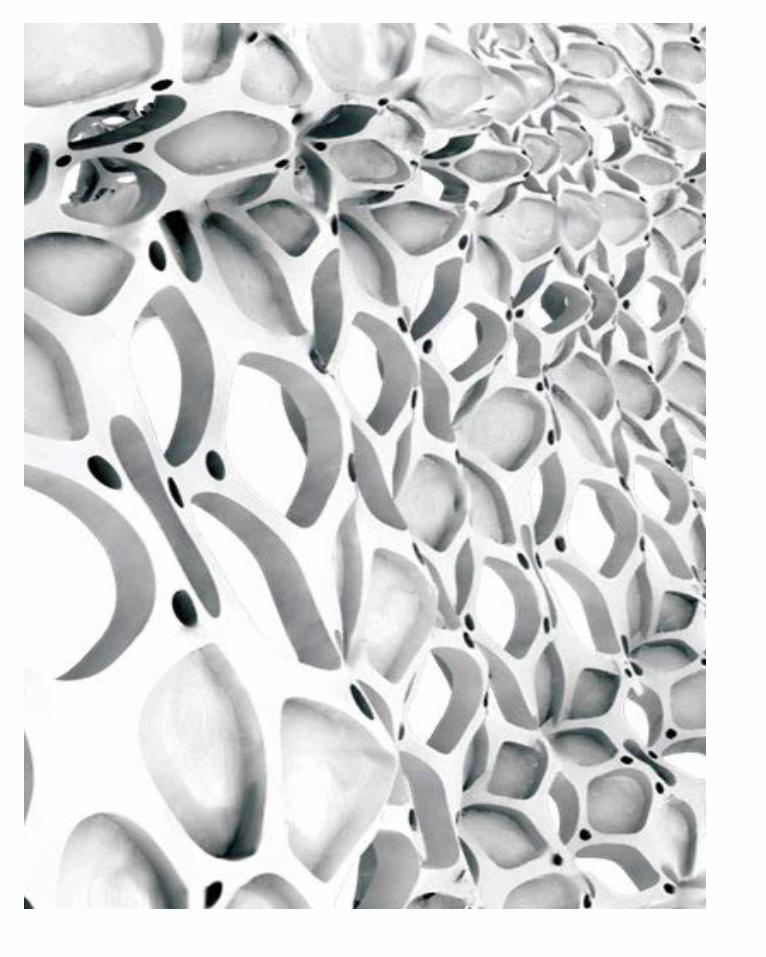
ContentsIntroduction...............................................................1
Part A Conceptulisation...........................................2 A.1. Design Futuring.......................................................3 A.2. Design Computation.................................................7 A.3. Composition/Generation...........................................9 A.4. Conclusion.............................................................11 A.5. Learning Outcomes.................................................12 A.6. Appendix - Algorithmic Sketches...............................14
Part B Criteria Design..............................................15 B.1. Research Field........................................................16 B.2. Case Study 1.0........................................................18 B.3. Case Study 2.0........................................................30 B.4. Technique: Development..........................................35 B.5. Technique: Prototypes..............................................51 B.6. Technique: Proposal.................................................53 B.7. Learning Objectives and Outcomes.............................58 B.8. Appendix - Algorithmic Sketches................................59
Part C Detailed Design..............................................65 C.1. Design Concept........................................................66 C.2. Tectonic Elements & Prototypes.................................77 C.3. Final Detail Model....................................................85 C.4. Learning Objectives and Outcomes.............................93
1 CONCEPTUALISATION
About me
My name is Jia Jia Shen. I am a 3rd year architecture student currently studying in The University of Melbourne. I was born in Australia and grew up in China. For me, Majoring in architecture is kind of an inevitable but struggling choice. To be honest, I was kind of lost with my future at that time and the only thing I know was that I wanted to do something with physics and aesthetic as they were respectively my strength and interest. Architecture happened to be the combination of them. At that time, the only basic drawing skill I had was only chinese painting and it actually made me afraid to major in architecture as I felt very behind. However, I was fascinated by the beauty of handmaking as well as historical architecture and the culture involved.
It is actually a surprise for me that now I had overcome two years in architecture major. I had to say that architecture is really not an easy job. The past two years I had explored the various aspects of architecture and the beauty of architecture for me now is not only the architecture itself but also the process of designing in terms of how various ideas can be translated into architecture and how things can be constructed. Architecture, now in my opinion, creates experience for people and the designers try to communicate with people through architecture which is the medium. Arhitecture is also shaping the society so it is a really important component in our life.
communicate with people through architecture which is the medium. Arhitecture is also shaping the society so it is a really important component in our life.
The skill I have developed through the course is the hand drawing skill and the model making skill. Photoshop is the only software I have touched on and have a basic skill for. I think that the lack of software skill is the main reason that I spent more time on how to draw a clear and neat floor plan instead of thinking of how to explore the concept of the design. In this studio, I really want to gain the basic skill of Rhino and Grashopper to assist my design in the future.
The idea of parametric is a vague idea in my mind at the moment. I am interested in the parametric product since it has a very modern sense and is a really interesting kind of designing way depending on software. I believe that parametric design has a big future in the architecture field so I am really looking forward to learn both parametric theory and using Rhino in this studio.
Introduction
CONCEPTUALISATION 2
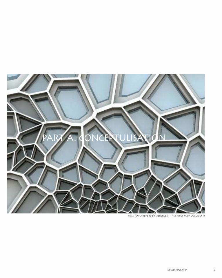
FIg.1: (explaIn here & reFerence at the end oF your document)
PART A. CONCEPTULISATION
the idea of speculative design which asks designers to consider various possibility of future instead of trying to pin down the future was suggested by Anthony Dunne and Fiona Raby [1]. With the development of technology, architecture has become a design practice that architects throw in their ideas that contribute to the culture and ongoing disciplinary discourse. This is also the idea of design futuring.
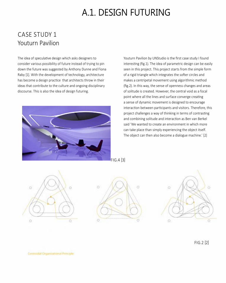
youturn pavilion by unStudio is the first case study I found interesting (fig.1). the idea of parametric design can be easily seen in this project. This project starts from the simple form of a rigid triangle which integrates the softer circles and makes a centripetal movement using algorithmic method (fig.2). In this way, the sense of openness changes and areas of solitude is created. However, the central void as a focal point where all the lines and surface converge creating a sense of dynamic movement is designed to encourage interaction between participants and visitors. therefore, this project challenges a way of thinking in terms of contrasting and combining solitude and interaction as Ben van Berkel said ‘We wanted to create an environment in which more can take place than simply experiencing the object itself. The object can then also become a dialogue machine.’ [2]
caSe Study 1youturn pavilion
FIg.2 [2]
FIg.4 [3]
A.1. deSign Futuring
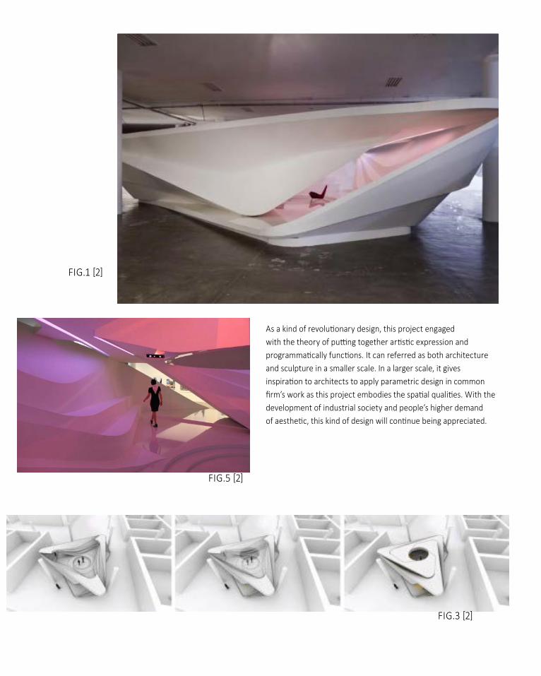
as a kind of revolutionary design, this project engaged with the theory of putting together artistic expression and programmatically functions. It can referred as both architecture and sculpture in a smaller scale. In a larger scale, it gives inspiration to architects to apply parametric design in common firm’s work as this project embodies the spatial qualities. With the development of industrial society and people’s higher demand of aesthetic, this kind of design will continue being appreciated.
FIg.1 [2]
FIg.3 [2]
FIg.5 [2]
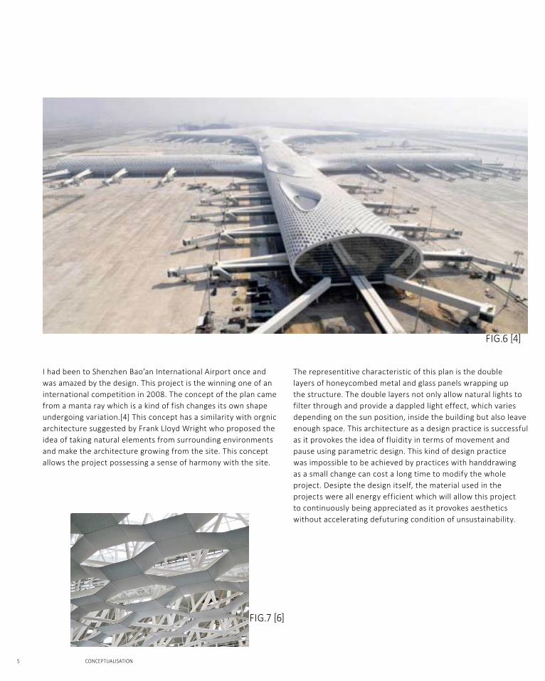
FIg.6 [4]
FIg.7 [6]
5 CONCEPTUALISATION
The representitive characteristic of this plan is the double layers of honeycombed metal and glass panels wrapping up the structure. The double layers not only allow natural lights to filter through and provide a dappled light effect, which varies depending on the sun position, inside the building but also leave enough space. This architecture as a design practice is successful as it provokes the idea of fluidity in terms of movement and pause using parametric design. This kind of design practice was impossible to be achieved by practices with handdrawing as a small change can cost a long time to modify the whole project. Desipte the design itself, the material used in the projects were all energy efficient which will allow this project to continuously being appreciated as it provokes aesthetics without accelerating defuturing condition of unsustainability.
I had been to Shenzhen Bao’an International Airport once and was amazed by the design. This project is the winning one of an international competition in 2008. The concept of the plan came from a manta ray which is a kind of fish changes its own shape undergoing variation.[4] This concept has a similarity with orgnic architecture suggested by Frank Lloyd Wright who proposed the idea of taking natural elements from surrounding environments and make the architecture growing from the site. This concept allows the project possessing a sense of harmony with the site.
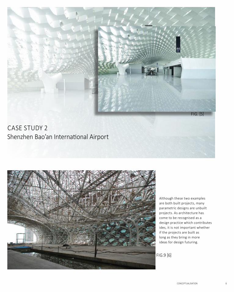
caSe Study 2Shenzhen Bao’an International airport
FIg. [5]
FIg.9 [6]
CONCEPTUALISATION 6
Although these two examples are both built projects, many parametric designs are unbuilt projects. As architecture has come to be recognised as a design practice which contributes ides, it is not important whether if the projects are built as long as they bring in more ideas for design futuring.
caSe Study 1Heydar Aliyev Center
FIG.10
FIG.12
FIG.11
7 CONCEPTUALISATION
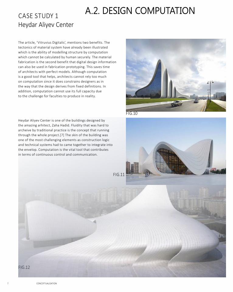
The article, ‘Vitruvius Digitalis’, mentions two benefits. The tectonics of material system have already been illustrated which is the ability of modelling structure by computation which cannot be calculated by human securely. The material fabrication is the second benefit that digital design information can also be used in fabrication prototyping. This saves time of architects with perfect models. Although computation is a good tool that helps, architects cannot rely too much on computation since it does constrains designers as in the way that the design derives from fixed definitions. In addition, computation cannot use its full capacity due to the challenge for faculties to produce in reality.
Heydar Aliyev Center is one of the buildings designed by the amazing arhitect, Zaha Hadid. Fluidity that was hard to archeive by traditional practice is the concept that running through the whole project.[7] The skin of the building was one of the most challenging elements as construction logic and technical systems had to came together to integrate into the envelop. Computation is the vital tool that contributes in terms of continuous control and communication.
A.2. deSign COMPutAtiOn
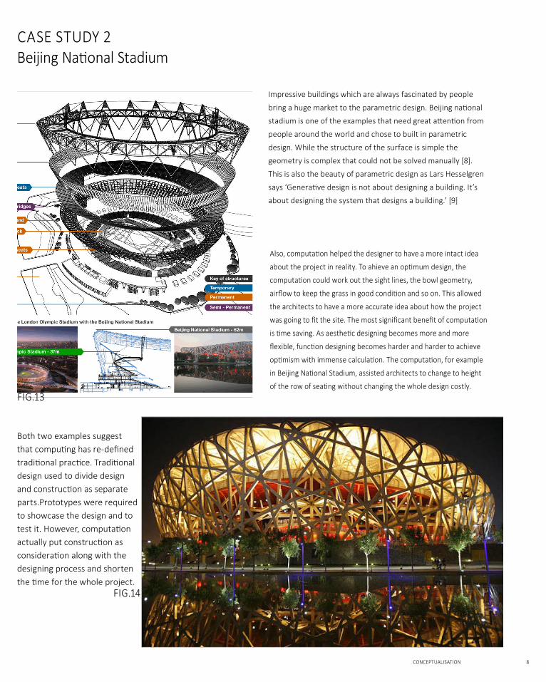
Impressive buildings which are always fascinated by people
bring a huge market to the parametric design. Beijing national
stadium is one of the examples that need great attention from
people around the world and chose to built in parametric
design. While the structure of the surface is simple the
geometry is complex that could not be solved manually [8].
This is also the beauty of parametric design as Lars Hesselgren
says ‘generative design is not about designing a building. It’s
about designing the system that designs a building.’ [9]
also, computation helped the designer to have a more intact idea
about the project in reality. to ahieve an optimum design, the
computation could work out the sight lines, the bowl geometry,
airflow to keep the grass in good condition and so on. this allowed
the architects to have a more accurate idea about how the project
was going to fit the site. the most significant benefit of computation
is time saving. as aesthetic designing becomes more and more
flexible, function designing becomes harder and harder to achieve
optimism with immense calculation. the computation, for example
in Beijing national Stadium, assisted architects to change to height
of the row of seating without changing the whole design costly.
Both two examples suggest that computing has re-defined traditional practice. traditional design used to divide design and construction as separate parts.Prototypes were required to showcase the design and to test it. however, computation actually put construction as consideration along with the designing process and shorten the time for the whole project.
FIG.14
caSe Study 2Beijing national Stadium
FIG.13
CONCEPTUALISATION 8
A.2. deSign COMPutAtiOn
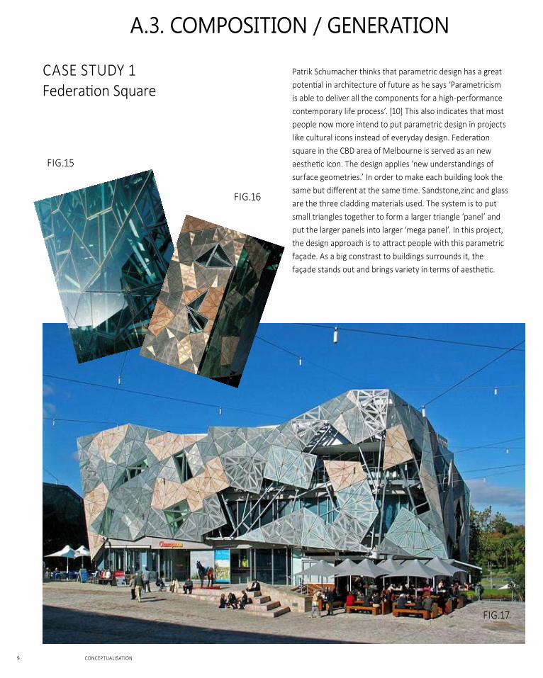
Patrik Schumacher thinks that parametric design has a great potential in architecture of future as he says ‘parametricism is able to deliver all the components for a high-performance contemporary life process’. [10] This also indicates that most people now more intend to put parametric design in projects like cultural icons instead of everyday design. Federation square in the CBD area of Melbourne is served as an new aesthetic icon. the design applies ‘new understandings of surface geometries.’ In order to make each building look the same but different at the same time. Sandstone,zinc and glass are the three cladding materials used. The system is to put small triangles together to form a larger triangle ‘panel’ and put the larger panels into larger ‘mega panel’. In this project, the design approach is to attract people with this parametric façade. As a big constrast to buildings surrounds it, the façade stands out and brings variety in terms of aesthetic.
caSe Study 1Federation Square
A.3. COMPOSitiOn / generAtiOn
FIG.17
FIG.16
FIG.15
9 CONCEPTUALISATION
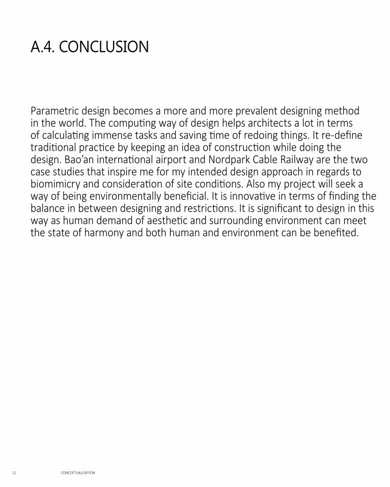
‘each station has its own unique context, topography, altitude and circulation. We studied natural phenomena such as glacial moraines and ice movements – as we wanted each station to use the fluid language of natural ice formations, like a frozen stream on the mountainside.’ -------------Zaha Hadid
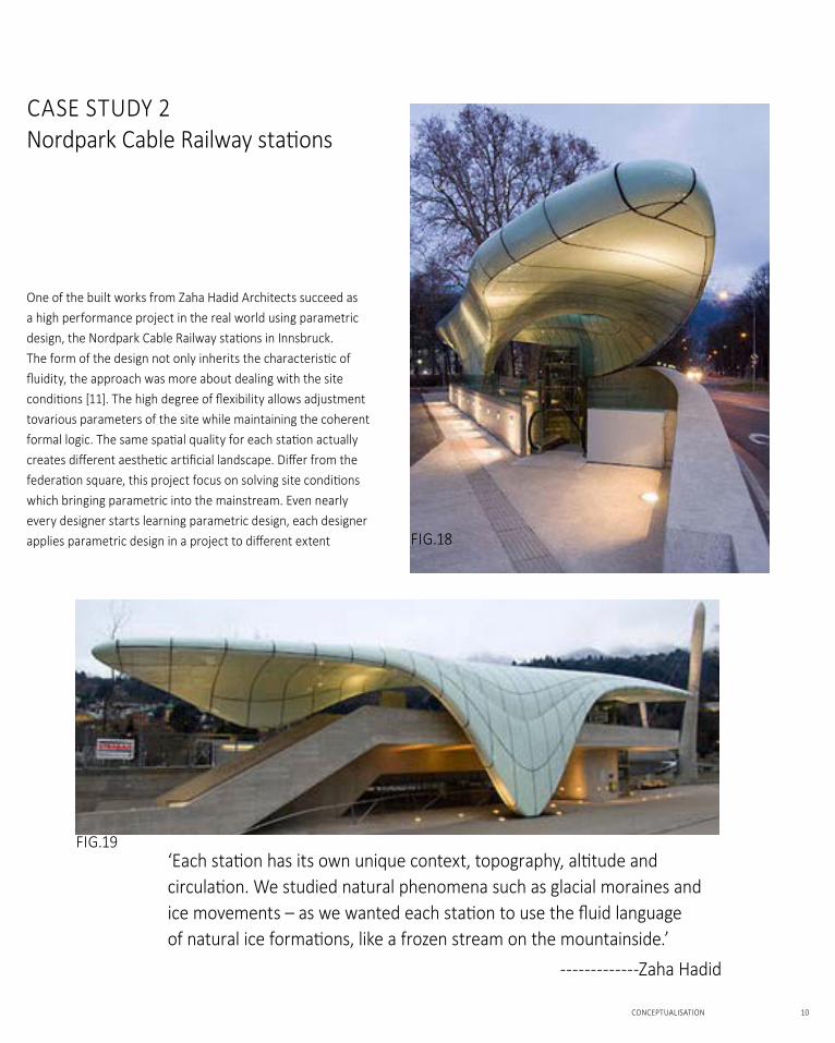
One of the built works from Zaha Hadid Architects succeed as a high performance project in the real world using parametric design, the nordpark cable railway stations in Innsbruck. the form of the design not only inherits the characteristic of fluidity, the approach was more about dealing with the site conditions [11]. the high degree of flexibility allows adjustment tovarious parameters of the site while maintaining the coherent formal logic. the same spatial quality for each station actually creates different aesthetic artificial landscape. differ from the federation square, this project focus on solving site conditions which bringing parametric into the mainstream. Even nearly every designer starts learning parametric design, each designer applies parametric design in a project to different extent
caSe Study 2nordpark cable railway stations
FIG.19
FIG.18
CONCEPTUALISATION 10
Parametric design becomes a more and more prevalent designing method in the world. the computing way of design helps architects a lot in terms of calculating immense tasks and saving time of redoing things. It re-define traditional practice by keeping an idea of construction while doing the design. Bao’an international airport and nordpark cable railway are the two case studies that inspire me for my intended design approach in regards to biomimicry and consideration of site conditions. also my project will seek a way of being environmentally beneficial. It is innovative in terms of finding the balance in between designing and restrictions. It is significant to design in this way as human demand of aesthetic and surrounding environment can meet the state of harmony and both human and environment can be benefited.
A.4. COnCluSiOn
11 CONCEPTUALISATION

A.5. leArning OutCOMeS
CONCEPTUALISATION 12
Parametric design was only a professional term to me at the beginning of the semester. By learning the Grasshopper I gain an understanding about how parametric design works. The experience of learning this parametric theory has open up a new world of architecture that I’ve never touched on. The beauty of architecture for me was more about historical architecture and the way people constructed architecture with poor conditions of technology. however, parametric design explores the beauty of technology and, for me, has a strong sense of connection with the contemporary world. also learning the software improves my skills as an architecture student. If I’ve learnt software skills in an early stage I would had more intact idea of my own project in the early design stage and would be able to spend more time on designing process.
[1] anthony dunne & Fiona raby, Speculative everything (mIt press, 2013), pp. 1-9
[2] Karen cilento, ‘youturn pavilion/unStudio’, archdaily
<http://www.archdaily.com/79421/youturn-pavilion-unstudio/> [ accessed 20 march 2015]
[3] danya, ‘youturn pavilion/unStudio’, arch20
<http://www.arch2o.com/youturn-pavilion-unstudios/> [ accessed 20 march 2015]
[4] Studio Fuksas, ‘Shenzhen Bao’an International airport/Studio Fuksas’, archdaily
<http://www.archdaily.com/472197/shenzhen-bao-an-international-airport-studio-fuksas/> [ accessed 20 march 2015]
[5] Phyllis Richardson, ‘New airport terminal puts Shenzhen on the global architecture map’, gizmag <http://www.gizmag.com/fuksas-shenzhen-airport/30060/> [ accessed 20 march 2015]
[6] Fuksas <http://twwhlspls.com/fuksas/>
[7] Zaha Hadid Architects, ‘Heydar Aliyev Center/Zaha Hadid Architects’, archdaily
<http://www.archdaily.com/448774/heydar-aliyev-center-zaha-hadid-architects/> [ accessed 20 march 2015]
[8]designbuild, ’Beijing national Stadium, ‘the Bird’s nest’,china’
<http://www.designbuild-network.com/projects/national_stadium/> [ accessed 20 march2015]
[9] nicolai ouroussoff, ‘olympic Stadium With a desiign to remember’, the new york times,
<http://www.nytimes.com/2008/08/05/sports/olympics/05nest.html?pagewanted=all&_r=1& > [ accessed 20 march 2015]
[10] John macarthur, ‘Federation Square’, architectureau,
<http://architectureau.com/articles/federation-square/> [ accessed 20 march 2015]
[11] Zaha Hadid Architects, ‘Nordpark Cable Railway’, arcspace.com,
<http://www.arcspace.com/features/zaha-hadid-architects/nordpark-cable-railway/> [accessed 20 march 2015]
REFERENCE
13 CONCEPTUALISATION
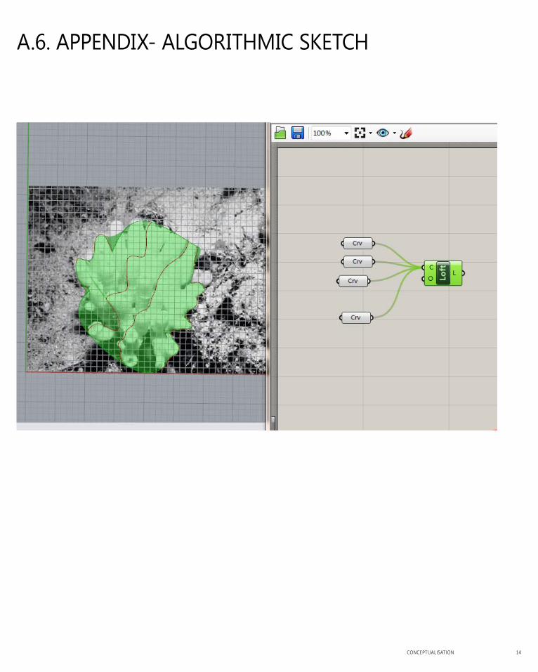
A.6. APPendix- AlgOrithMiC SketCh
CONCEPTUALISATION 14
15
Part B.Criteria Design
COnCePtUaLisatiOn 16
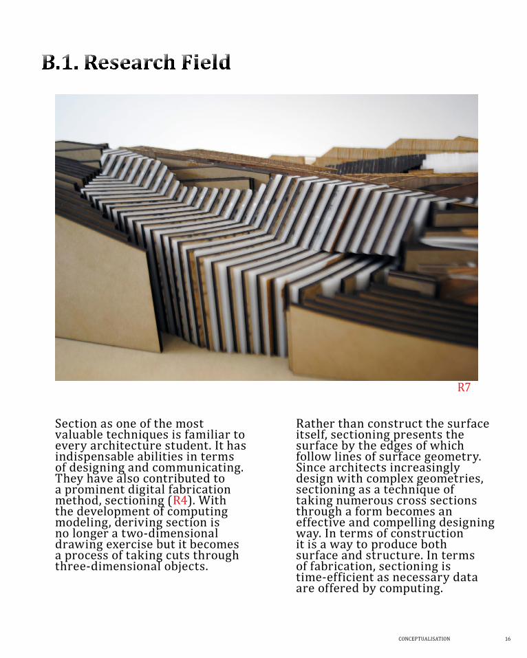
rather than construct the surface itself, sectioning presents the surface by the edges of which follow lines of surface geometry. since architects increasingly design with complex geometries, sectioning as a technique of taking numerous cross sections through a form becomes an effective and compelling designing way. in terms of construction it is a way to produce both surface and structure. in terms of fabrication, sectioning is time-efficient as necessary data are offered by computing.
section as one of the most valuable techniques is familiar to every architecture student. it has indispensable abilities in terms of designing and communicating. they have also contributed to a prominent digital fabrication method, sectioning (r4). With the development of computing modeling, deriving section is no longer a two-dimensional drawing exercise but it becomes a process of taking cuts through three-dimensional objects.
r7
17
PRECEDENT 1 - BaNq REsNTauRaNT
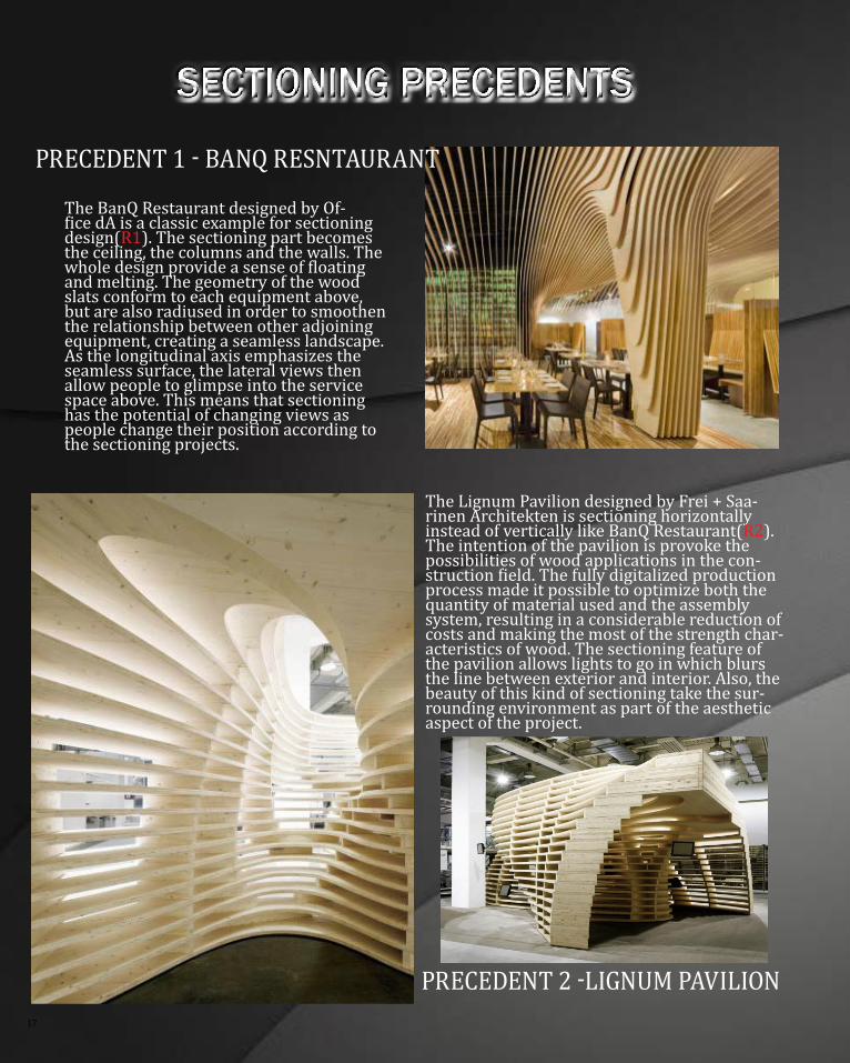
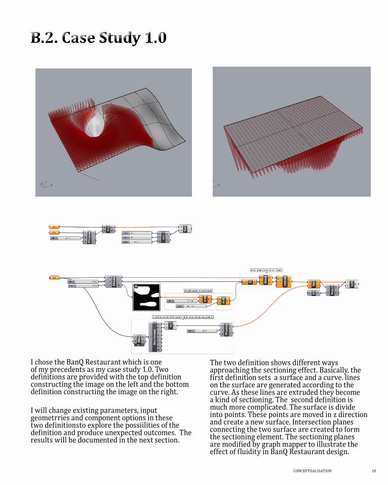
The Banq Restaurant designed by Of-fice da is a classic example for sectioning design(r1). the sectioning part becomes the ceiling, the columns and the walls. the whole design provide a sense of floating and melting. the geometry of the wood slats conform to each equipment above, but are also radiused in order to smoothen the relationship between other adjoining equipment, creating a seamless landscape. as the longitudinal axis emphasizes the seamless surface, the lateral views then allow people to glimpse into the service space above. this means that sectioning has the potential of changing views as people change their position according to the sectioning projects.
the Lignum Pavilion designed by Frei + saa-rinen architekten is sectioning horizontally instead of vertically like Banq Restaurant(r2). the intention of the pavilion is provoke the possibilities of wood applications in the con-struction field. The fully digitalized production process made it possible to optimize both the quantity of material used and the assembly system, resulting in a considerable reduction of costs and making the most of the strength char-acteristics of wood. the sectioning feature of the pavilion allows lights to go in which blurs the line between exterior and interior. also, the beauty of this kind of sectioning take the sur-rounding environment as part of the aesthetic aspect of the project.
PRECEDENT 2 -LigNum PaviLiON
Sectioning PrecedentS
COnCePtUaLisatiOn 18
i chose the Banq Restaurant which is one of my precedents as my case study 1.0. two definitions are provided with the top definition constructing the image on the left and the bottom definition constructing the image on the right.
i will change existing parameters, input geometrries and component options in these two definitionsto explore the possiilities of the definition and produce unexpected outcomes. The results will be documented in the next section.
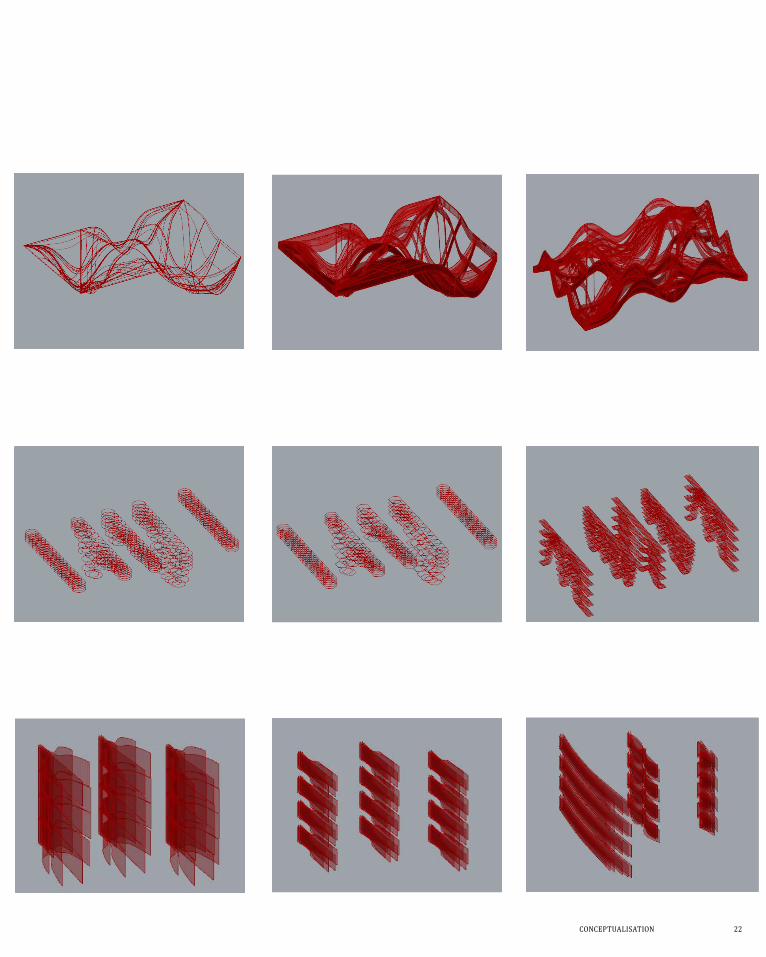
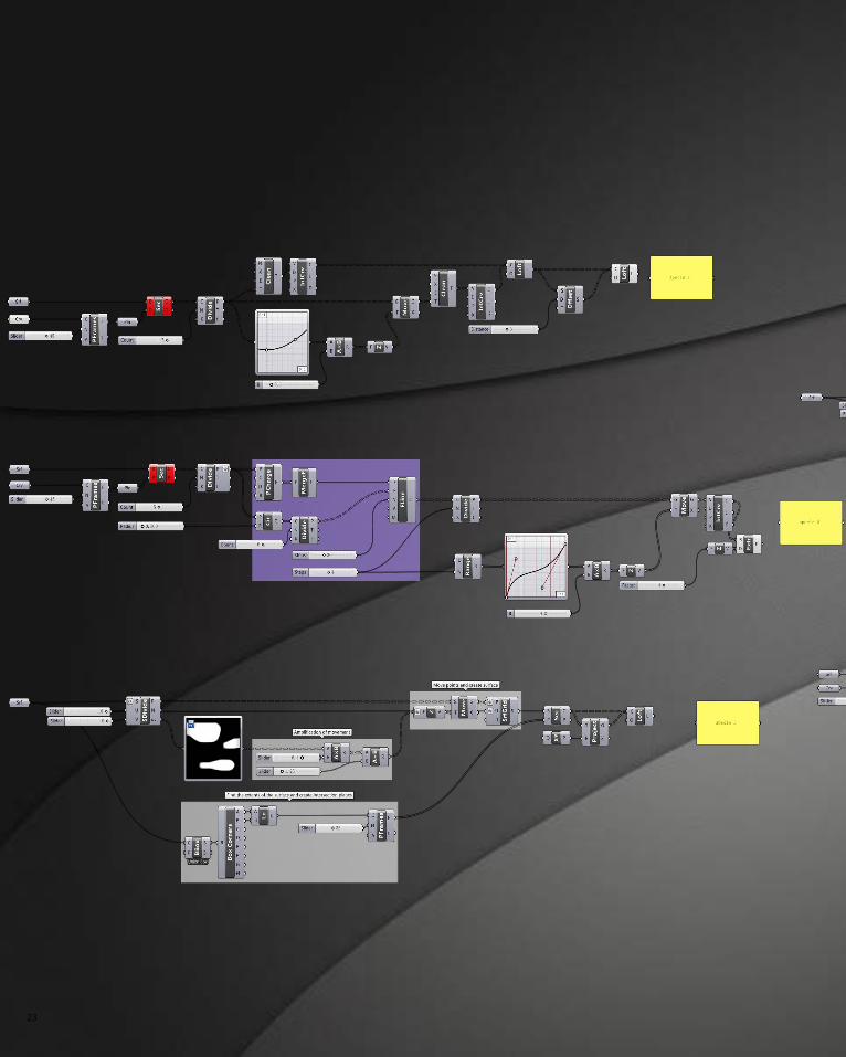
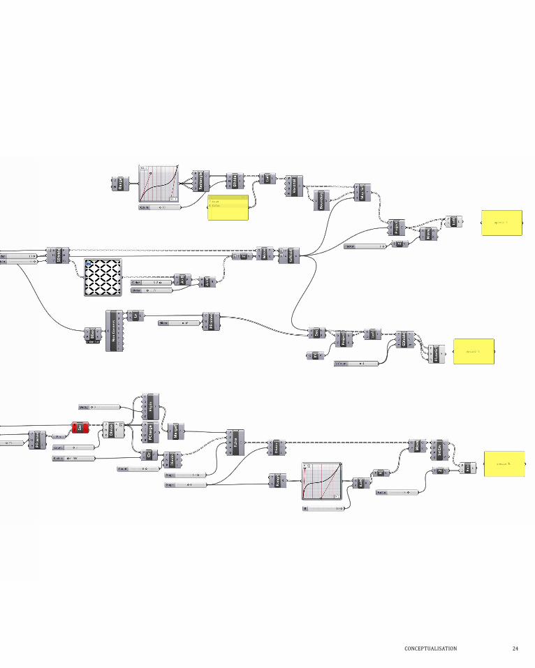
The two definition shows different ways approaching the sectioning effect. Basically, the first definition sets a surface and a curve. lines on the surface are generated according to the curve. as these lines are extruded they become a kind of sectioning. The second definition is much more complicated. the surface is divide into points. these points are moved in z direction and create a new surface. intersection planes connecting the two surface are created to form the sectioning element. the sectioning planes are modified by graph mapper to illustrate the effect of fluidity in Banq Restaurant design.
19
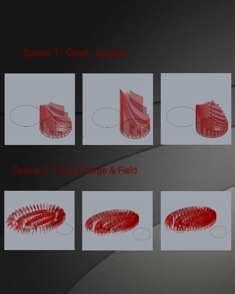
Specie 1 - Graph Mapper
Specie 2 - Point Charge & Field
COnCePtUaLisatiOn 20
Specie 1 - Graph Mapper
21
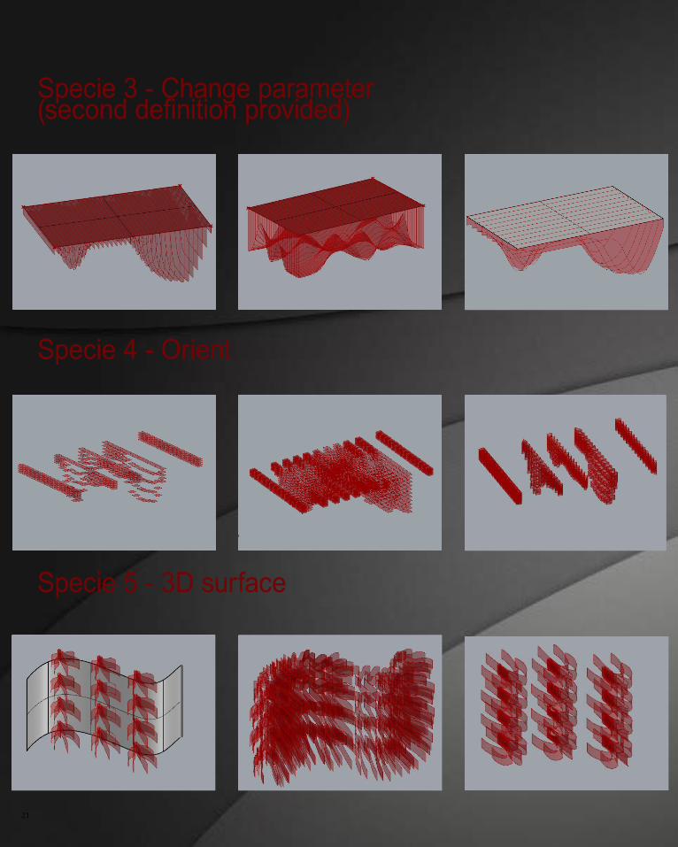
Specie 3 - Change parameter (second definition provided)
Specie 4 - Orient
Specie 5 - 3D surface
COnCePtUaLisatiOn 22
23
COnCePtUaLisatiOn 24
25
seLeCtiOn Criteria
The brief of the project is to design forms that fill up the gaps
between trees and vegetation to block or somehow eliminate
the view of the built environment. In order to achieve this
approach. There are few things need to be considered:
- the design should have both solid part that ‘block’ the view and void part that allows trees and vegetation to fill in
- the design should somehow include the idea of sectioning as it is the research field of the project’s technique.
- Biomimicry should be intended to show in the project
- there should be variation in the sectioning. as the design is for a particular site, variation will allow adjustment in specific loaction for the design.
COnCePtUaLisatiOn 26
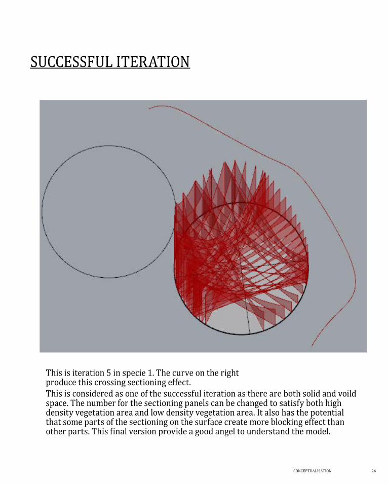
sUCCessFUL iteratiOn
this is iteration 5 in specie 1. the curve on the right produce this crossing sectioning effect.this is considered as one of the successful iteration as there are both solid and voild space. the number for the sectioning panels can be changed to satisfy both high density vegetation area and low density vegetation area. it also has the potential that some parts of the sectioning on the surface create more blocking effect than other parts. This final version provide a good angel to understand the model.
27
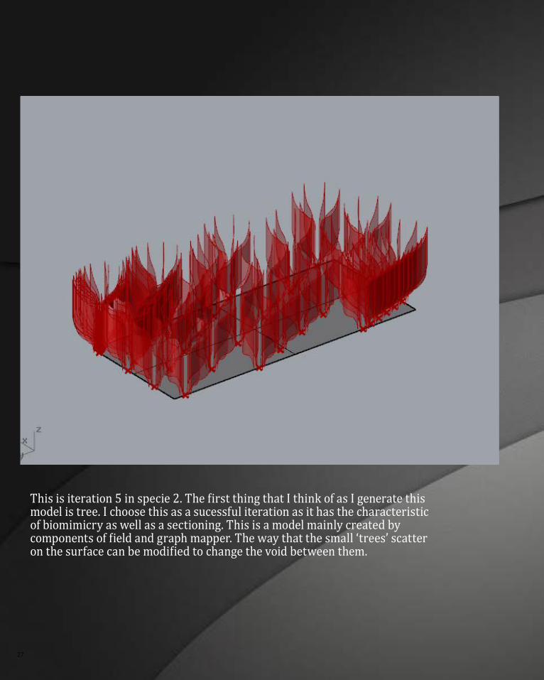
This is iteration 5 in specie 2. The first thing that i think of as i generate this model is tree. i choose this as a sucessful iteration as it has the characteristic of biomimicry as well as a sectioning. this is a model mainly created by components of field and graph mapper. The way that the small ‘trees’ scatter on the surface can be modified to change the void between them.
COnCePtUaLisatiOn 28
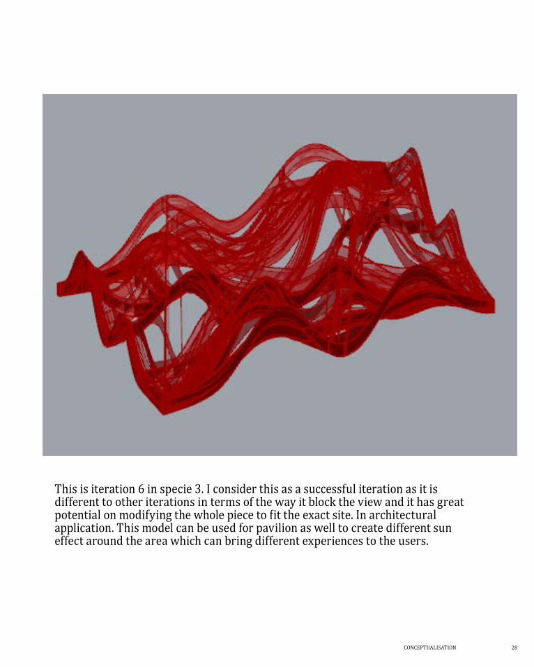
this is iteration 6 in specie 3. i consider this as a successful iteration as it is different to other iterations in terms of the way it block the view and it has great potential on modifying the whole piece to fit the exact site. in architectural application. this model can be used for pavilion as well to create different sun effect around the area which can bring different experiences to the users.
29
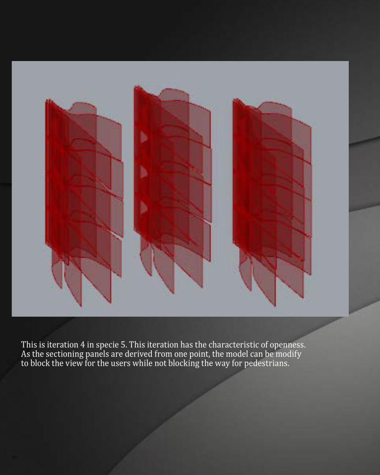
this is iteration 4 in specie 5. this iteration has the characteristic of openness. as the sectioning panels are derived from one point, the model can be modify to block the view for the users while not blocking the way for pedestrians.
COnCePtUaLisatiOn 30
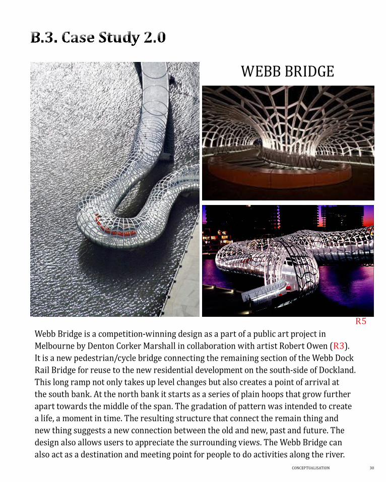
WeBB BriDge
Webb Bridge is a competition-winning design as a part of a public art project in melbourne by Denton Corker marshall in collaboration with artist Robert Owen (r3). it is a new pedestrian/cycle bridge connecting the remaining section of the Webb Dock rail Bridge for reuse to the new residential development on the south-side of Dockland. this long ramp not only takes up level changes but also creates a point of arrival at the south bank. at the north bank it starts as a series of plain hoops that grow further apart towards the middle of the span. the gradation of pattern was intended to create a life, a moment in time. the resulting structure that connect the remain thing and new thing suggests a new connection between the old and new, past and future. the design also allows users to appreciate the surrounding views. the Webb Bridge can also act as a destination and meeting point for people to do activities along the river.
r5
31
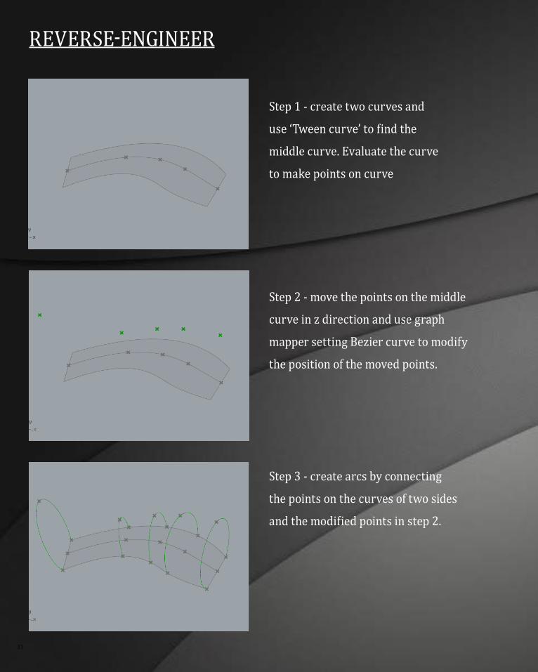
REvERsE-ENgiNEER
step 1 - create two curves and
use ‘Tween curve’ to find the
middle curve. evaluate the curve
to make points on curve
step 2 - move the points on the middle
curve in z direction and use graph
mapper setting Bezier curve to modify
the position of the moved points.
step 3 - create arcs by connecting
the points on the curves of two sides
and the modified points in step 2.
COnCePtUaLisatiOn 32
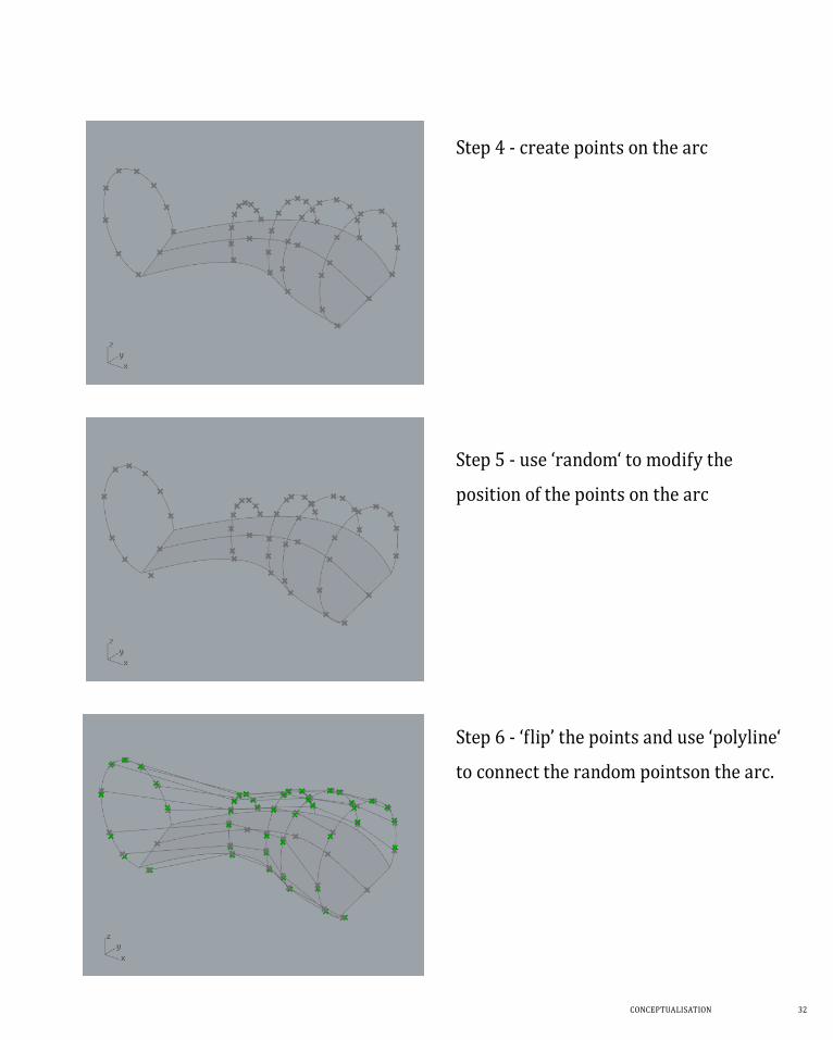
step 4 - create points on the arc
step 5 - use ‘random‘ to modify the
position of the points on the arc
step 6 - ‘flip’ the points and use ‘polyline‘
to connect the random pointson the arc.
33
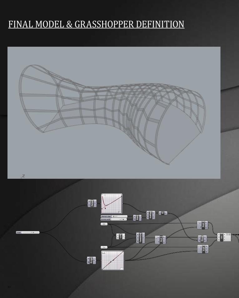
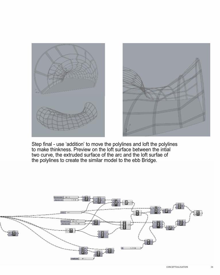
FiNaL mODEL & gRasshOPPER DEFiNiTiON
COnCePtUaLisatiOn 34
Step final - use ‘addition’ to move the polylines and loft the polylines to make thinkness. Preview on the loft surface between the intial two curve, the extruded surface of the arc and the loft surfae of the polylines to create the similar model to the ebb Bridge.
35
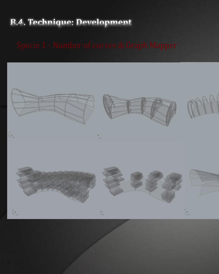
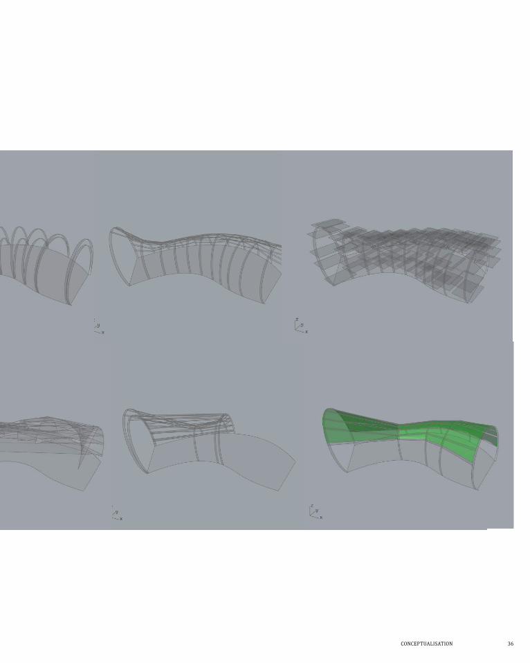
B.4. Technique: Development
specie 1 - Number of curves & graph mapper
COnCePtUaLisatiOn 36
37
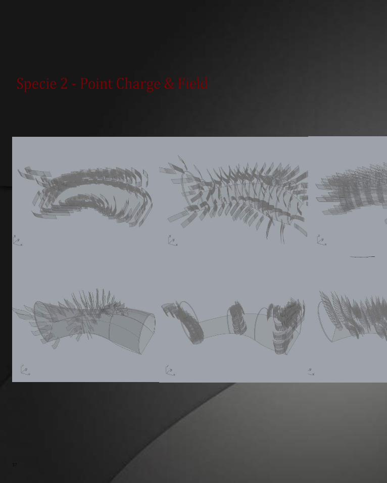
specie 2 - Point Charge & Field
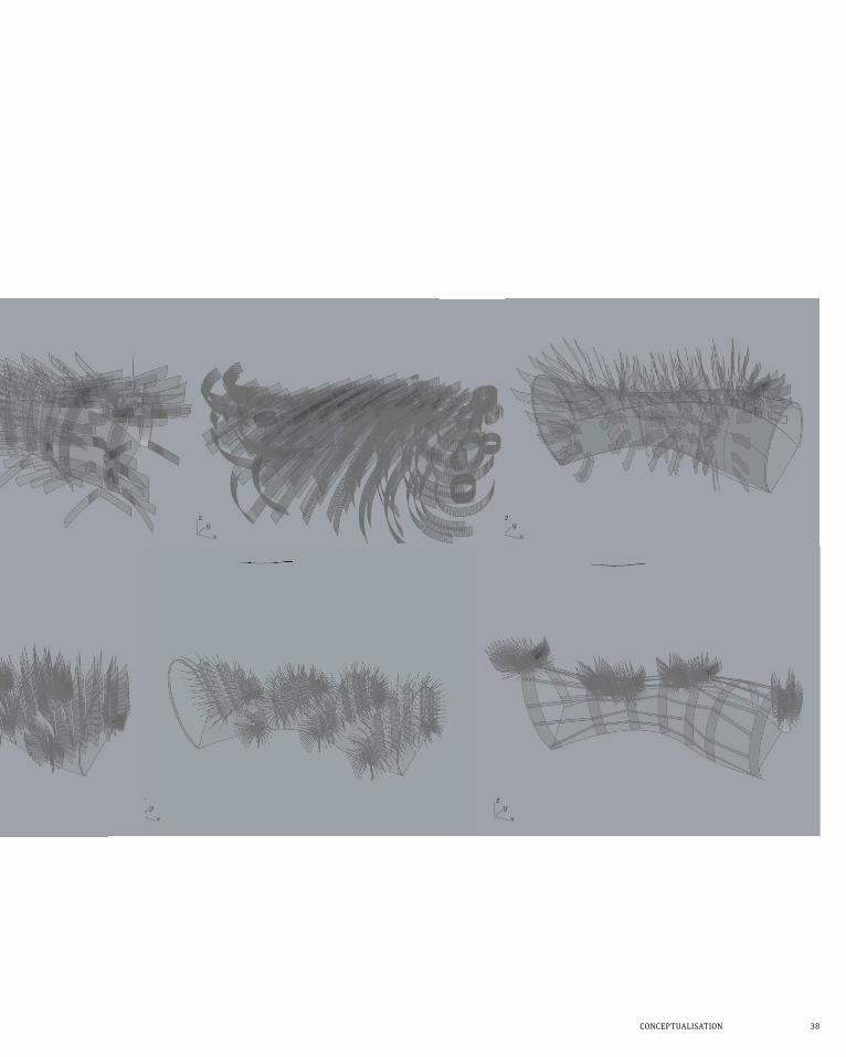
COnCePtUaLisatiOn 38
39
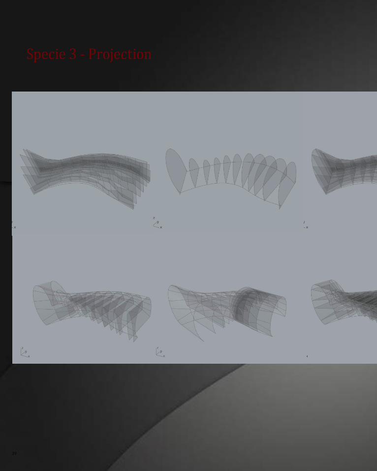
specie 3 - Projection
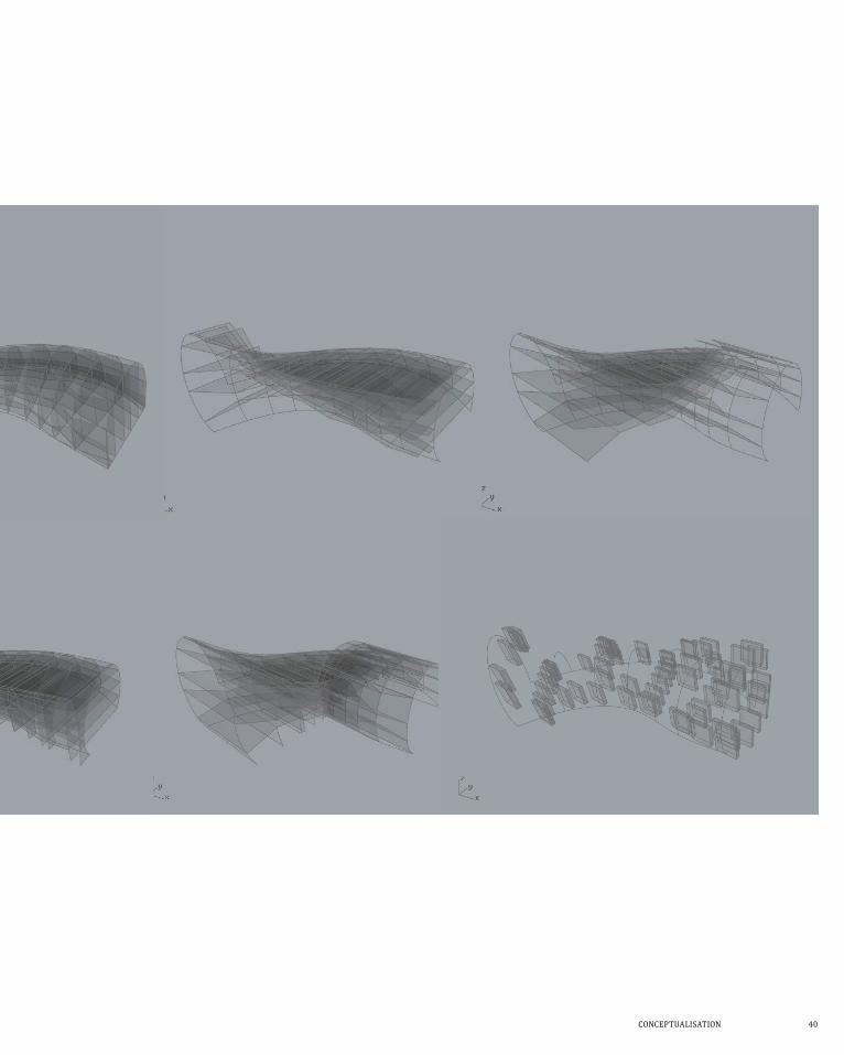
COnCePtUaLisatiOn 40
41
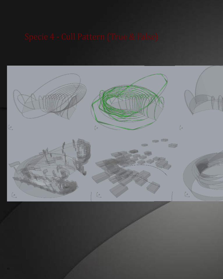
specie 4 - Cull Pattern (True & False)
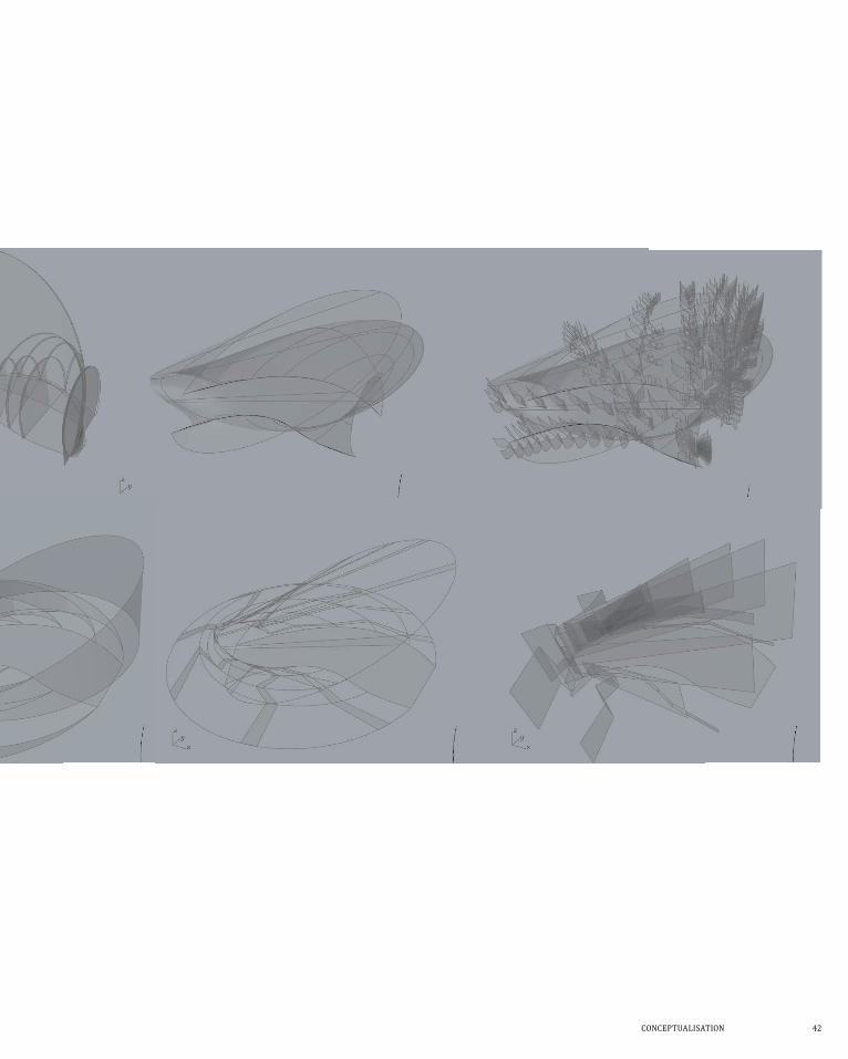
COnCePtUaLisatiOn 42
43
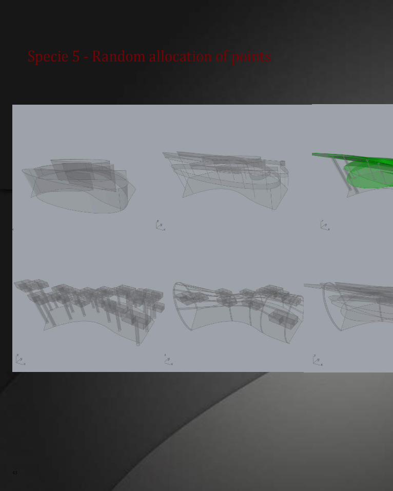
specie 5 - random allocation of points
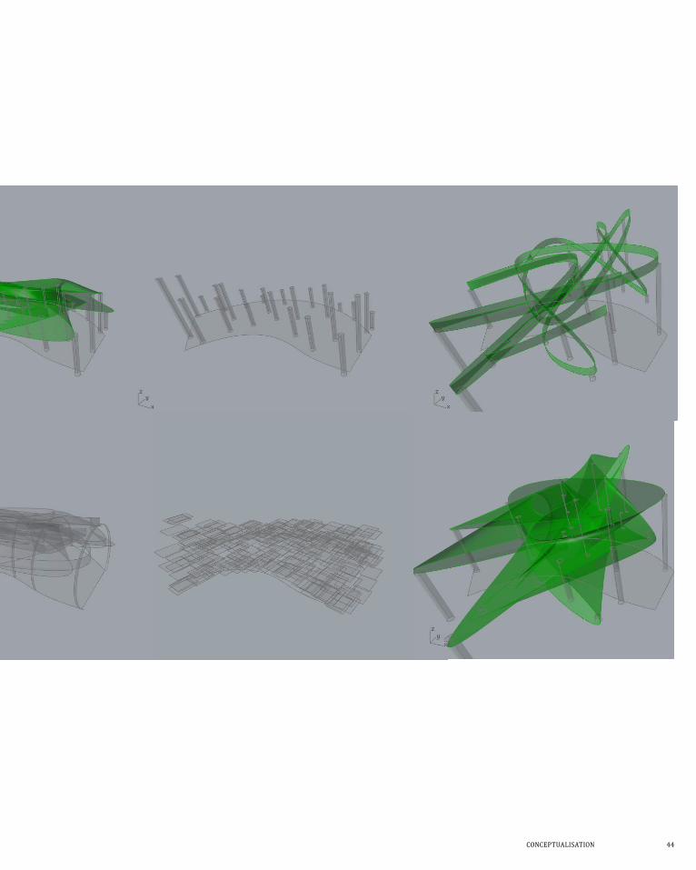
COnCePtUaLisatiOn 44
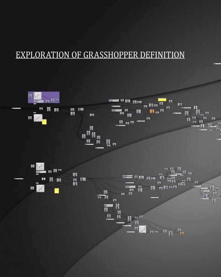
45
ExPLORaTiON OF gRasshOPPER DEFiNiTiON
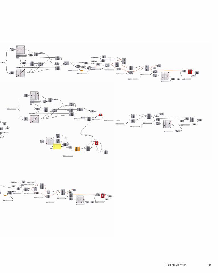
COnCePtUaLisatiOn 46
47
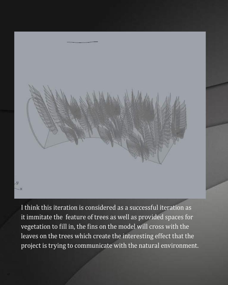
i think this iteration is considered as a successful iteration as it immitate the feature of trees as well as provided spaces for vegetation to fill in, the fins on the model will cross with the leaves on the trees which create the interesting effect that the project is trying to communicate with the natural environment.
COnCePtUaLisatiOn 48
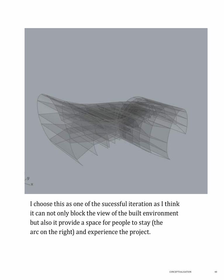
i choose this as one of the sucessful iteration as i think it can not only block the view of the built environment but also it provide a space for people to stay (the arc on the right) and experience the project.
49
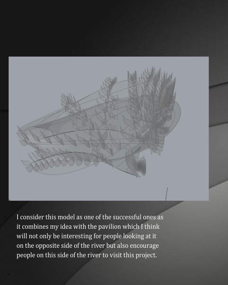
i consider this model as one of the successful ones as it combines my idea with the pavilion which i think will not only be interesting for people looking at it on the opposite side of the river but also encourage people on this side of the river to visit this project.
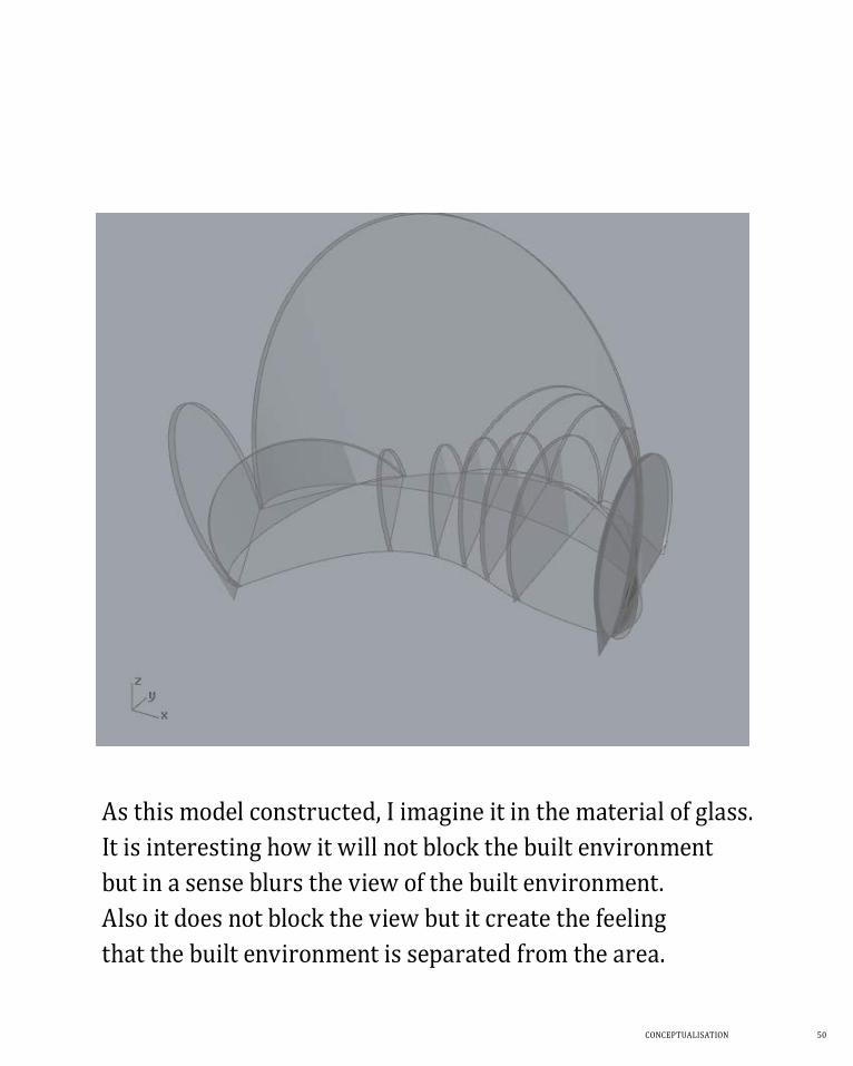
COnCePtUaLisatiOn 50
as this model constructed, i imagine it in the material of glass. it is interesting how it will not block the built environment but in a sense blurs the view of the built environment. also it does not block the view but it create the feeling that the built environment is separated from the area.
51
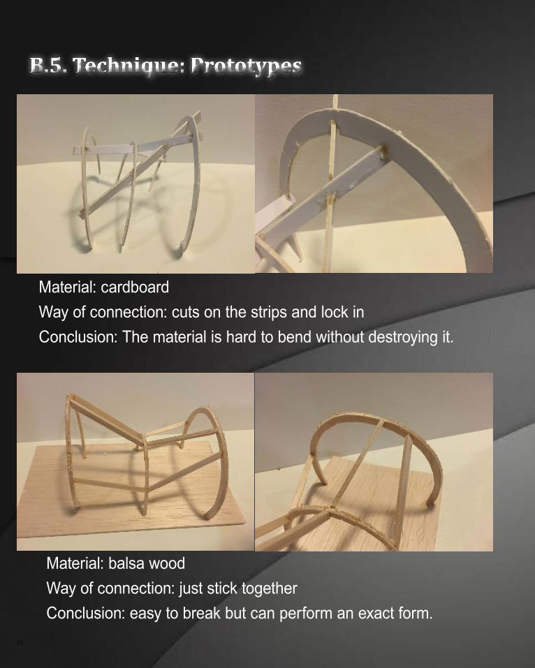
B.5. Technique: Prototypes
Material: cardboardWay of connection: cuts on the strips and lock in Conclusion: The material is hard to bend without destroying it.
Material: balsa woodWay of connection: just stick togetherConclusion: easy to break but can perform an exact form.
COnCePtUaLisatiOn 52
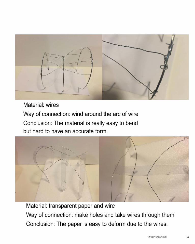
Material: wiresWay of connection: wind around the arc of wire Conclusion: The material is really easy to bend but hard to have an accurate form.
Material: transparent paper and wireWay of connection: make holes and take wires through themConclusion: The paper is easy to deform due to the wires.
53
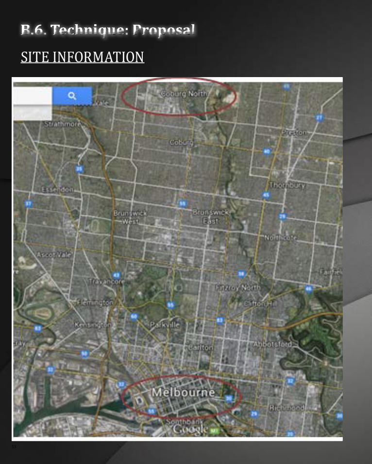
B.6. Technique: Proposal
siTE iNFORmaTiON
COnCePtUaLisatiOn 54
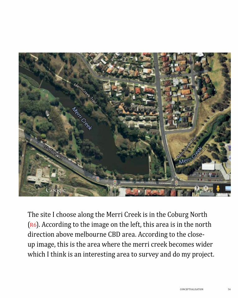
The site i choose along the merri Creek is in the Coburg North (r6). according to the image on the left, this area is in the north direction above melbourne CBD area. according to the close-up image, this is the area where the merri creek becomes wider which i think is an interesting area to survey and do my project.
55
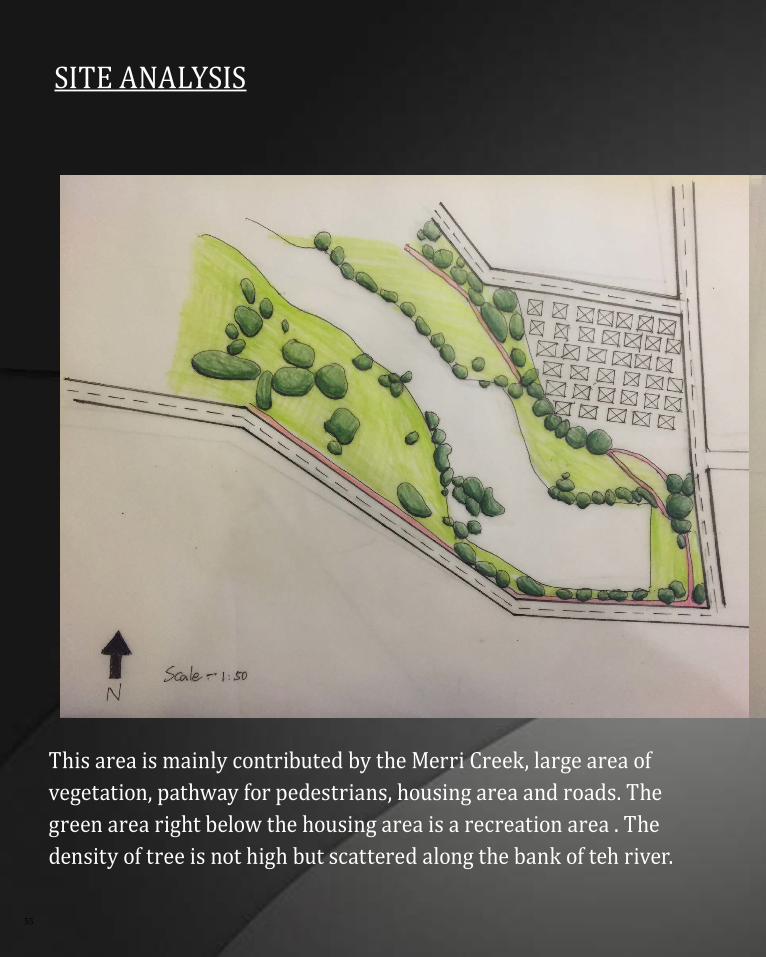
site anaLysis
This area is mainly contributed by the merri Creek, large area of vegetation, pathway for pedestrians, housing area and roads. the green area right below the housing area is a recreation area . the density of tree is not high but scattered along the bank of teh river.
COnCePtUaLisatiOn 56
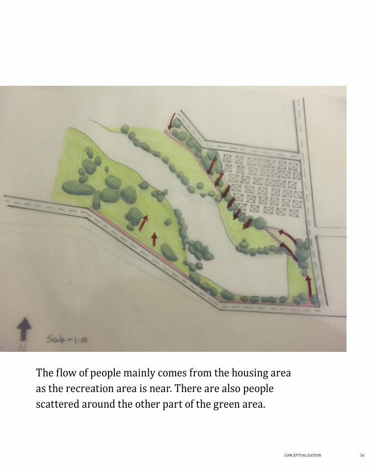
The flow of people mainly comes from the housing area as the recreation area is near. there are also people scattered around the other part of the green area.
57
PrOPOsaL
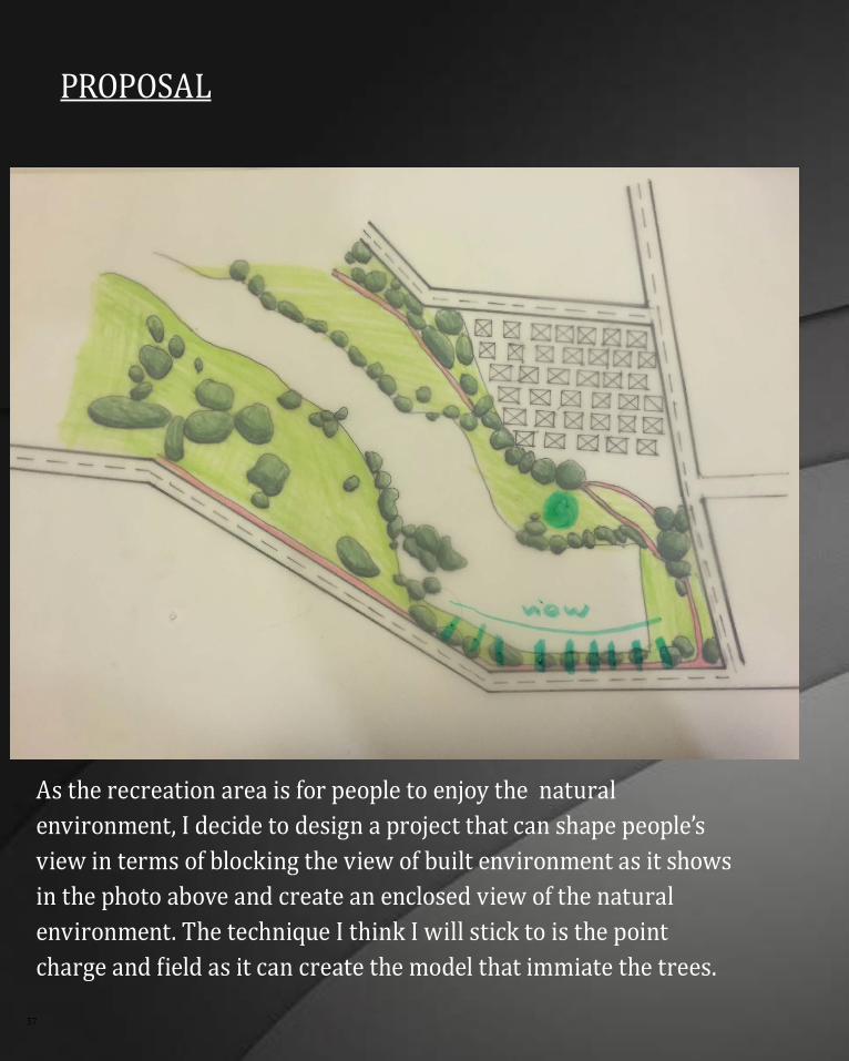
as the recreation area is for people to enjoy the natural environment, i decide to design a project that can shape people’s view in terms of blocking the view of built environment as it shows in the photo above and create an enclosed view of the natural environment. the technique i think i will stick to is the point charge and field as it can create the model that immiate the trees.
COnCePtUaLisatiOn 58
Exploring the definition to seek for different possibilities is a really time-consuming
task as i always got the components in red and don’t know where i actually get wrong
for the whole definition. also, when i get further and further in the definition which
makes the definition longer and longer, it always messes up my mind and takes ages
for me to go back and put previews on. however, during the part B section of training
for grasshopper i gradually get some kinds of logic and know how should i think in a
grasshopper logical way. and now when i sometimes get null components i know how
to think backwards to seek for answers or how to come out with the question that i can
type in google to search for answers. the other thing i get to learn is to post the question
on the discussion forum of grasshoper’s website. People there are always helpful.
The exploring definition exercise and decision of the selection criteria annoys me at
the early stage. however, when i get to explore more possibilities in the definition i
gradually understand how computation works in design process with developing a
brief. the more possibility, the more it helps the designers to think of the problem of the
project. as in my brief, i was initially want to design an architecture that can block the
view of the built environmen. however when i explores more possibilities of definition
i started to think about whether it will be better if i can intergate the architecture
with the existing natural elements. i also think about making a project that not only
for people looking at it but also for people who can actually walk in and experience it.
Computation design is not only a tool that help designer to design with parameters but
also a tool that can help the designers to think about more possibility of the project.
59
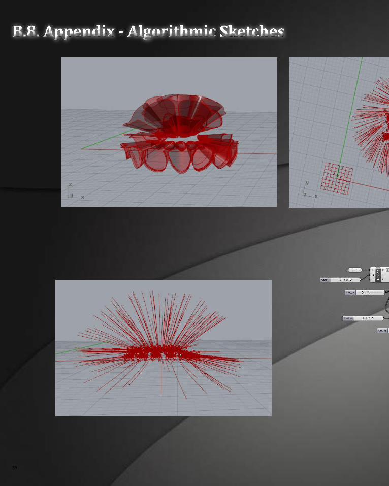
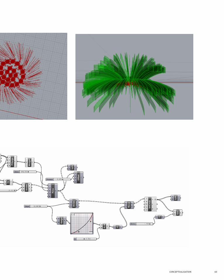
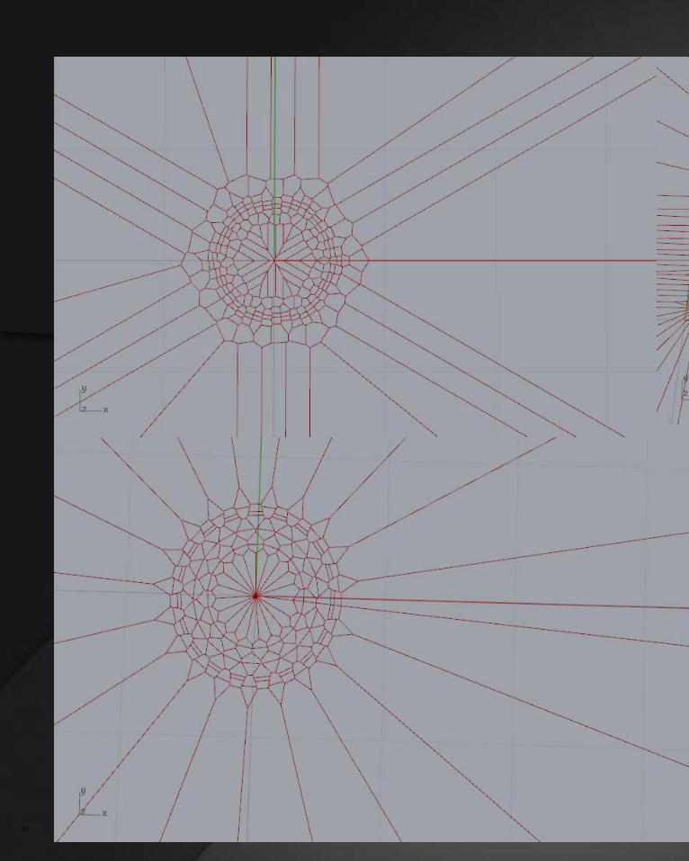
B.8. Appendix - Algorithmic Sketches
COnCePtUaLisatiOn 60
61
COnCePtUaLisatiOn 62
63
reFerenCe
Reference
1. ArchDaily, ‘BanQ/Office dA’ in ArchDaily <http://www.archdaily.com/42581/
banq-office-da/> [accessed 1 May 2015]
2. ArchDaily, ‘Lignum Pavilion/Frei + Saarinen Architekten’ in ArchDaily
<http://www.archdaily.com/274331/lignum-pavilion-frei-saarinen-architekten/> [ac-
cessed 1 May 2015]
3. Denton Corker Marshall in collaboration with artist Robert Owen, ‘Webb
Bridge’, in Australian Institute of Architects
<http://dynamic.architecture.com.au/awards_search?option=showaward&entry
no=20053006> [accessed 1 May 2015]
4. Lisa Iwamoto, ‘Sectioning’, in Digital Fabrications: Architectural and Material
Techniques (New York: Princeton Architectural Press), pp. 10-27
5. Ms Shannon McGrath, Australian Institute of Architects, digital image, 2005
<http://dynamic.architecture.com.au/awards_search?option=showaward&entry
no=20053006> [accessed 1 May 2015]
6. Sinclair Knight Merz & Fugro, Google maps, 2015
<https://www.google.com.au/maps/place/Merri+Creek,+Melbourne+VIC/@-
37.7338341,144.9693908,497m/data=!3m1!1e3!4m2!3m1!1s0x6ad645405fe293
1b:0x2a0456754b38dc50> [accessed 1 May 2015]
7. Tommy Heng, Designito, < https://designito.wordpress.com/architecture-de-
sign-studio-air/> [accessed 1 May 2015]
COnCePtUaLisatiOn 64
65
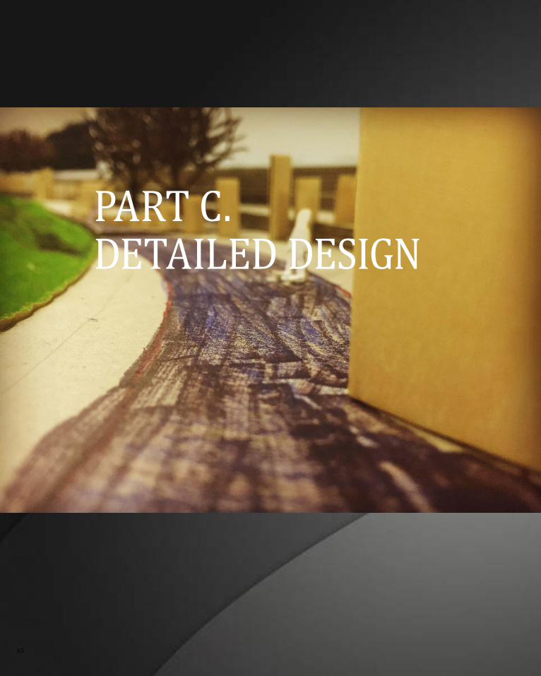
Part C.DetaiLeD Design
COnCePtUaLisatiOn 66
Address feedback from interim presentation
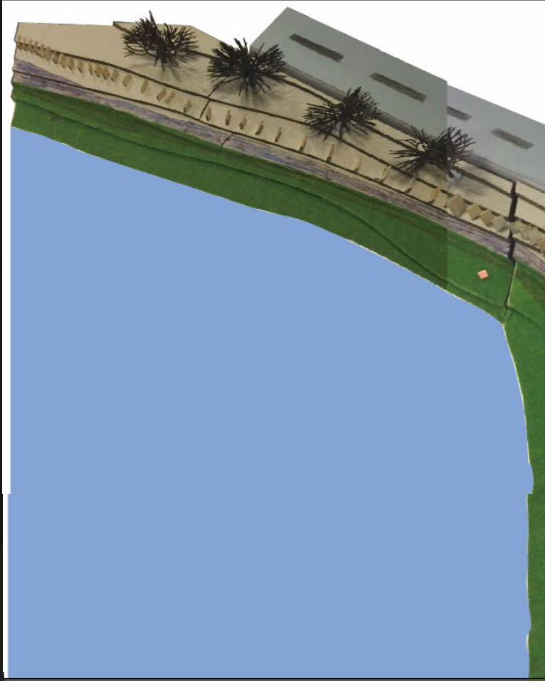
as stated in Part B, my concept was to design a project that can shape people’s view from the recreation area on one side of the river by blocking the view of the built environment on the opposite side of the river using panels between trees to create an enclosed natural environment for people to enjoy. the overall feedback from the interim presentation is that my idea of the concept is too vague in terms of the lack of site information, cell study and layers of meaning. the presentation was not supported by photos of the site. the panels that shaping people’s view are also not supported by any research study of human field of view and cell study of orientation of panels in rhino.
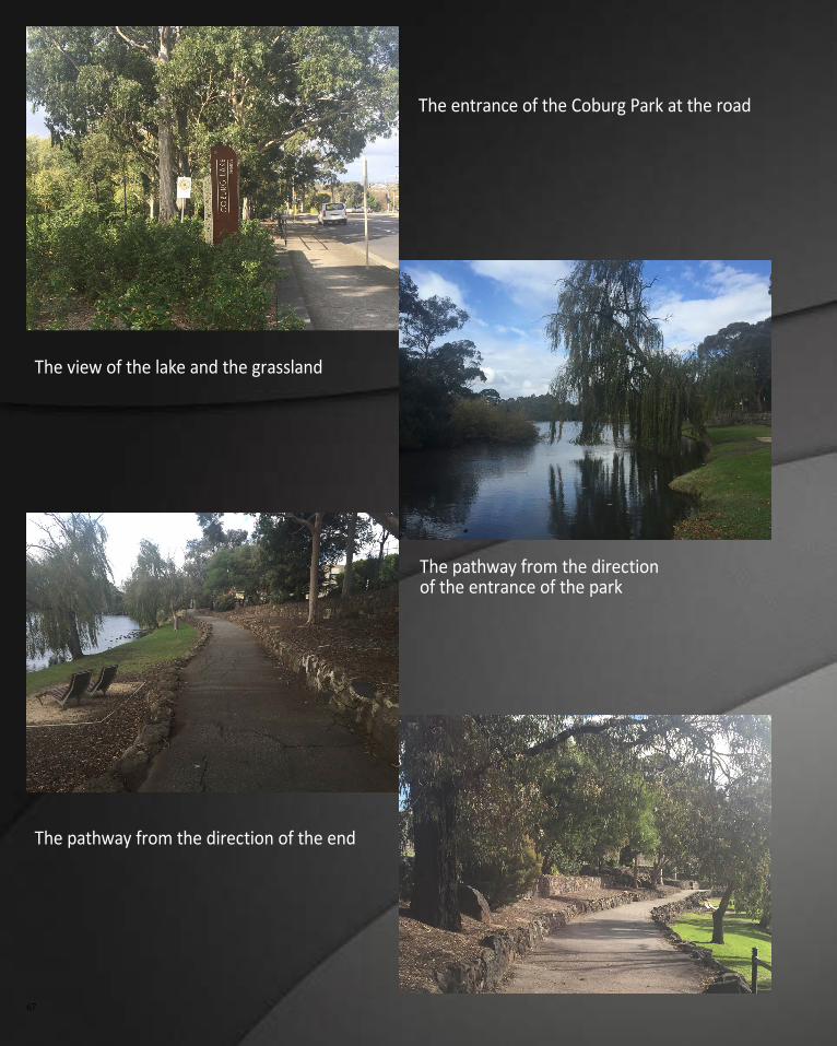
as tutors suggested, i went to the site to investigate and take photos.i found that visiting the site was much more helpful than scanning information on google earth. Before i went to the site i thought that the Coburg Lake reserve was near the housing area. however, the Coburg Lake Reserve is on the side of the road which is much nearer for people to see the built environment. the recreation facilities for children was also on this site which indicated that this is the area where visitors mostly stay. near the reacreation facility, there was a long pathway with various distribution of trees along the greatest lake area of the site. there were two spots with benches for visitors to sit and enjoy the view. the green area between the pathway and the lake is narrow. the study of the site help me to adjust my concept. as the long pathway is quieter compare to the area of the recreation facilities, i want to make this area a recreation for people who just want to rest and chat as well as enjoy the natural environment.
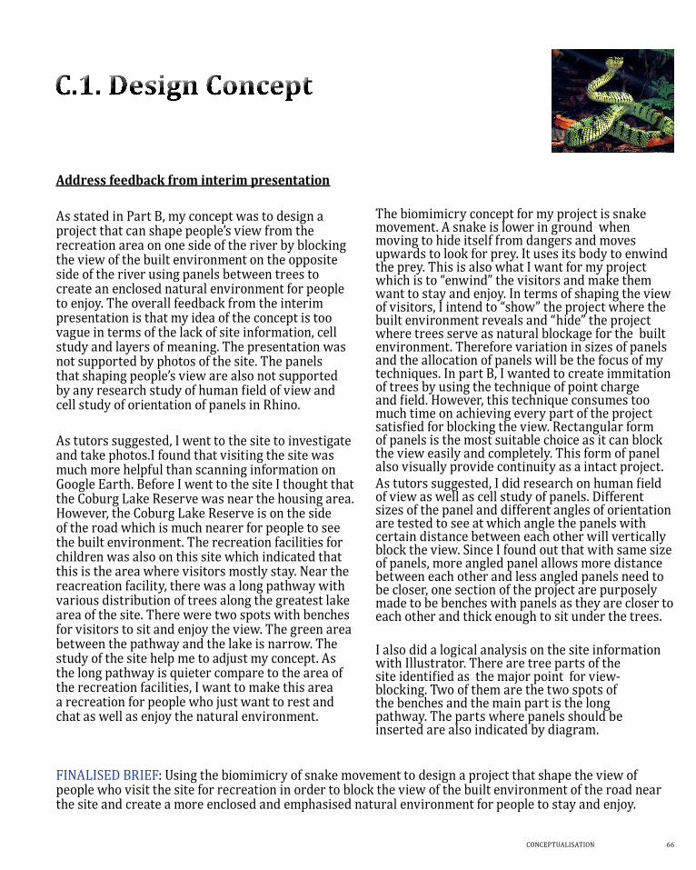
the biomimicry concept for my project is snake movement. a snake is lower in ground when moving to hide itself from dangers and moves upwards to look for prey. it uses its body to enwind the prey. this is also what i want for my project which is to “enwind” the visitors and make them want to stay and enjoy. in terms of shaping the view of visitors, i intend to “show” the project where the built environment reveals and “hide” the project where trees serve as natural blockage for the built environment. therefore variation in sizes of panels and the allocation of panels will be the focus of my techniques. in part B, i wanted to create immitation of trees by using the technique of point charge and field. however, this technique consumes too much time on achieving every part of the project satisfied for blocking the view. Rectangular form of panels is the most suitable choice as it can block the view easily and completely. this form of panel also visually provide continuity as a intact project.as tutors suggested, i did research on human field of view as well as cell study of panels. Different sizes of the panel and different angles of orientation are tested to see at which angle the panels with certain distance between each other will vertically block the view. since i found out that with same size of panels, more angled panel allows more distance between each other and less angled panels need to be closer, one section of the project are purposely made to be benches with panels as they are closer to each other and thick enough to sit under the trees.
i also did a logical analysis on the site information with illustrator. there are tree parts of the site identified as the major point for view-blocking. two of them are the two spots of the benches and the main part is the long pathway. the parts where panels should be inserted are also indicated by diagram.
FinaLiseD BrieF: Using the biomimicry of snake movement to design a project that shape the view of people who visit the site for recreation in order to block the view of the built environment of the road near the site and create a more enclosed and emphasised natural environment for people to stay and enjoy.
67
The entrance of the Coburg Park at the road
The view of the lake and the grassland
The pathway from the direction of the entrance of the park
The pathway from the direction of the end
COnCePtUaLisatiOn 68
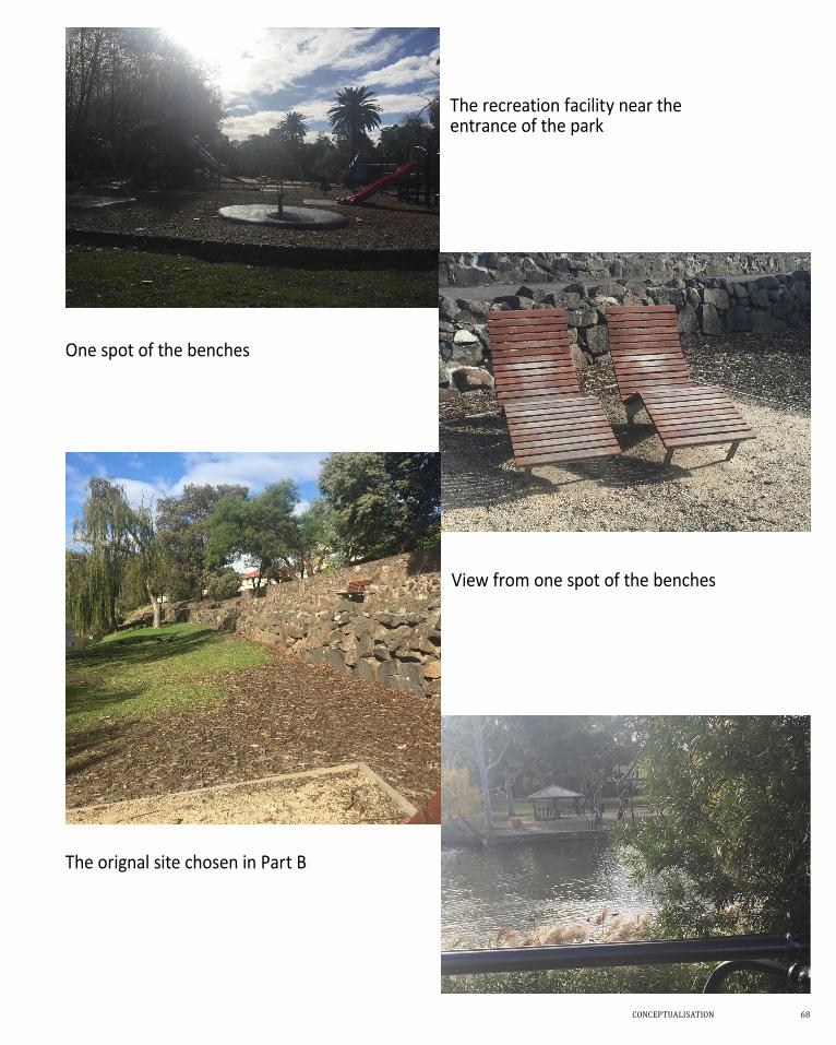
The recreation facility near the entrance of the park
One spot of the benches
View from one spot of the benches
The orignal site chosen in Part B
69
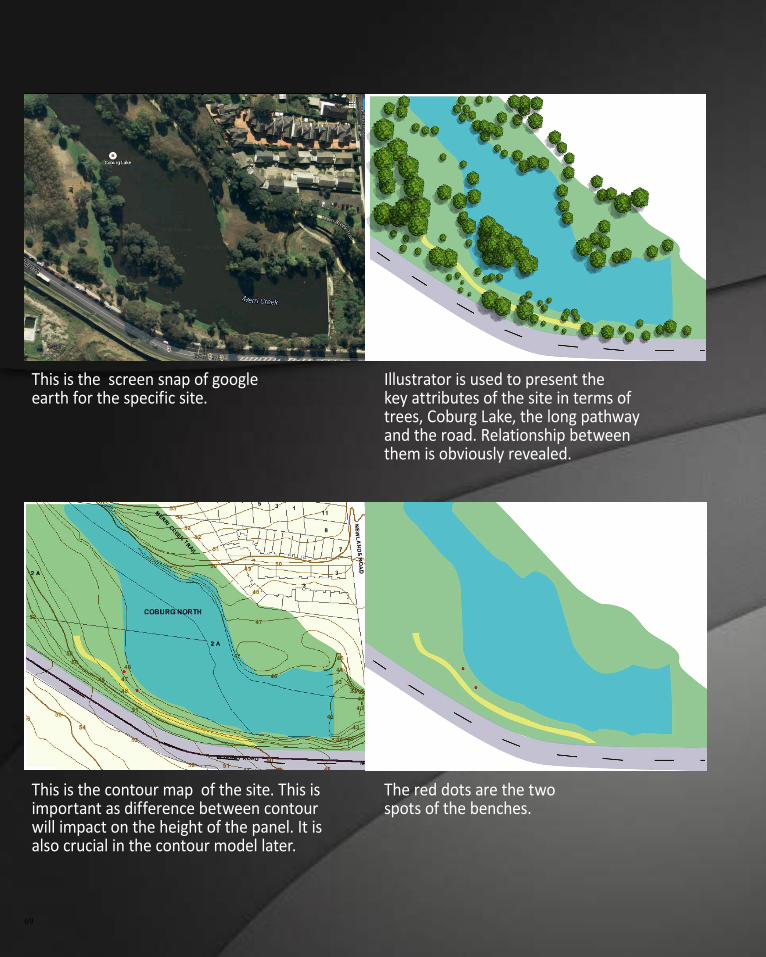
This is the screen snap of google earth for the specific site.
Illustrator is used to present the key attributes of the site in terms of trees, Coburg Lake, the long pathway and the road. Relationship between them is obviously revealed.
This is the contour map of the site. This is important as difference between contour will impact on the height of the panel. It is also crucial in the contour model later.
The red dots are the two spots of the benches.
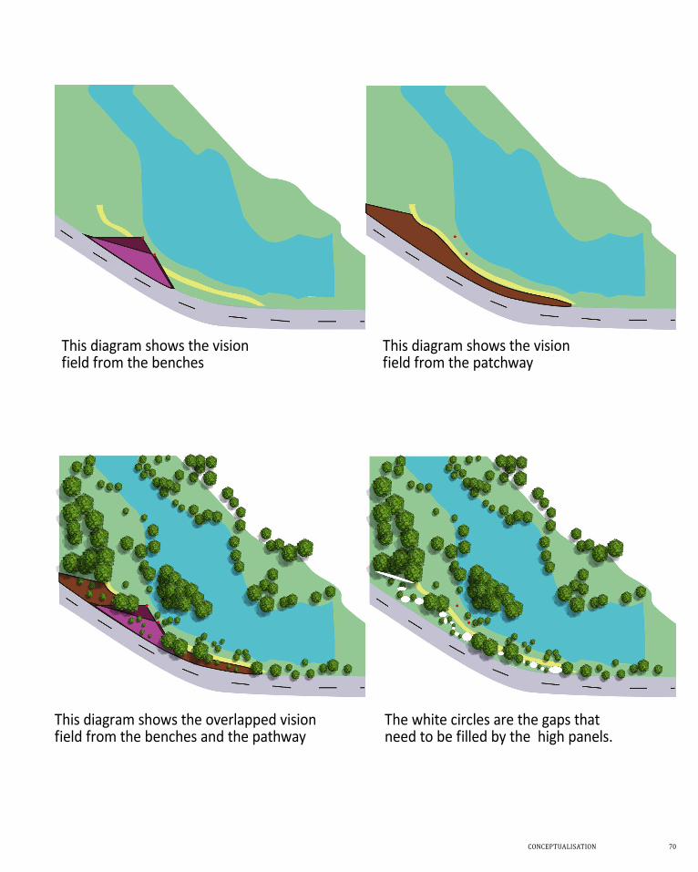
COnCePtUaLisatiOn 70
This diagram shows the vision field from the benches
This diagram shows the vision field from the patchway
This diagram shows the overlapped vision field from the benches and the pathway
The white circles are the gaps that need to be filled by the high panels.
71
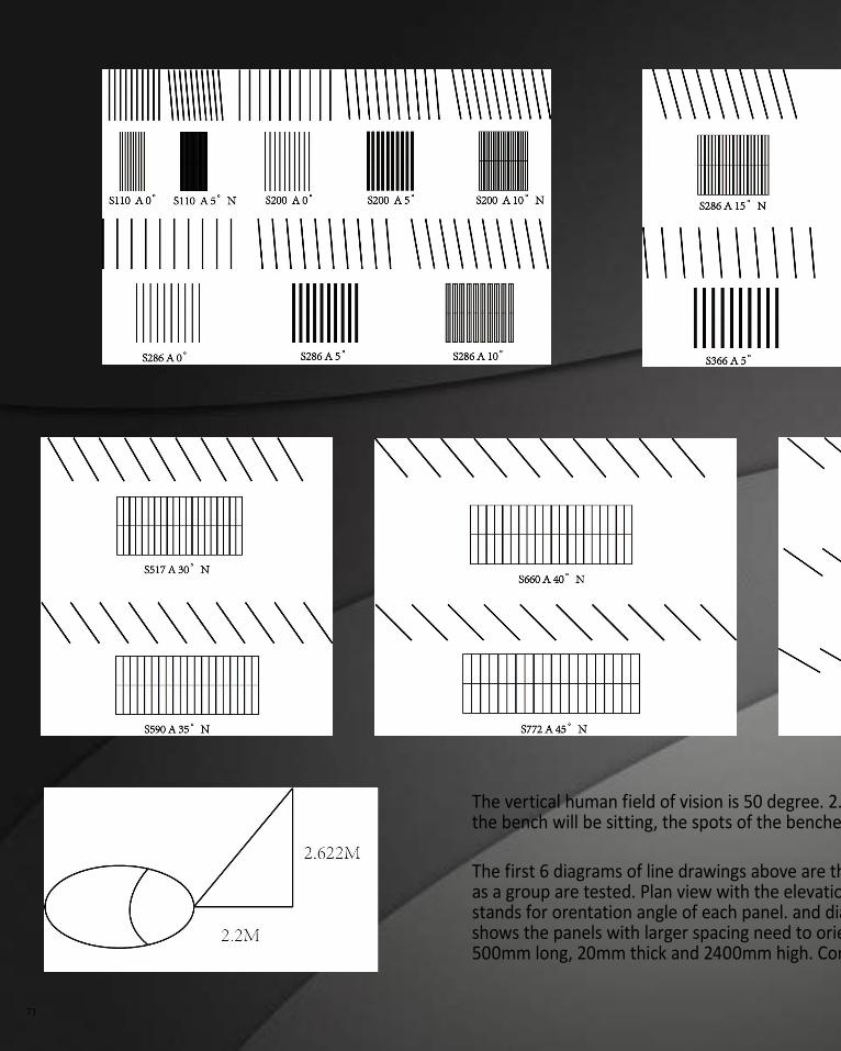
The vertical human field of vision is 50 degree. 2.2 meters is the longest distance between the pathway and the panels. As the people on the bench will be sitting, the spots of the benches are not taken into consideration for the decision of the height of the panels.
The first 6 diagrams of line drawings above are the cell study of the panels with 1000mm long, 20mm thick and 2400mm high. 10 panels as a group are tested. Plan view with the elevation view underneath are shown in process. "S" stands for spacing between panels. "A" stands for orentation angle of each panel. and diagram with "N" indicates that the view in elevation of the panels are totally blocked. It shows the panels with larger spacing need to orient more angle to block the view. The last diagram is the cell study of the panels with 500mm long, 20mm thick and 2400mm high. Compare to longer panel, shorter panel allows less spacing distance to block the view.
COnCePtUaLisatiOn 72
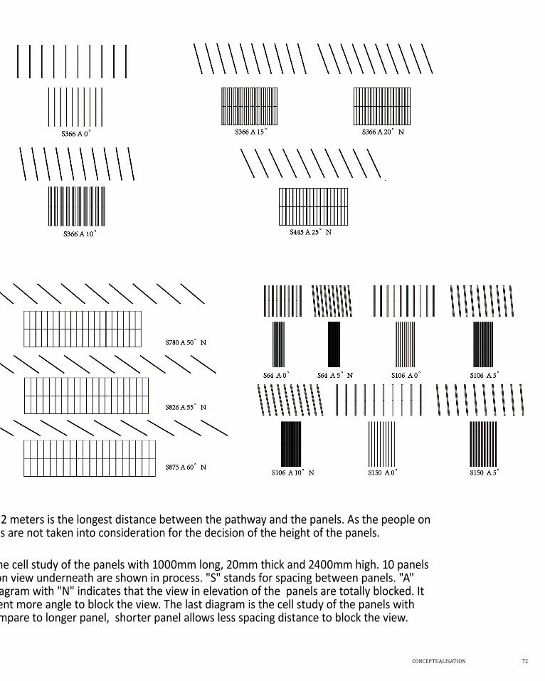
The vertical human field of vision is 50 degree. 2.2 meters is the longest distance between the pathway and the panels. As the people on the bench will be sitting, the spots of the benches are not taken into consideration for the decision of the height of the panels.
The first 6 diagrams of line drawings above are the cell study of the panels with 1000mm long, 20mm thick and 2400mm high. 10 panels as a group are tested. Plan view with the elevation view underneath are shown in process. "S" stands for spacing between panels. "A" stands for orentation angle of each panel. and diagram with "N" indicates that the view in elevation of the panels are totally blocked. It shows the panels with larger spacing need to orient more angle to block the view. The last diagram is the cell study of the panels with 500mm long, 20mm thick and 2400mm high. Compare to longer panel, shorter panel allows less spacing distance to block the view.
73
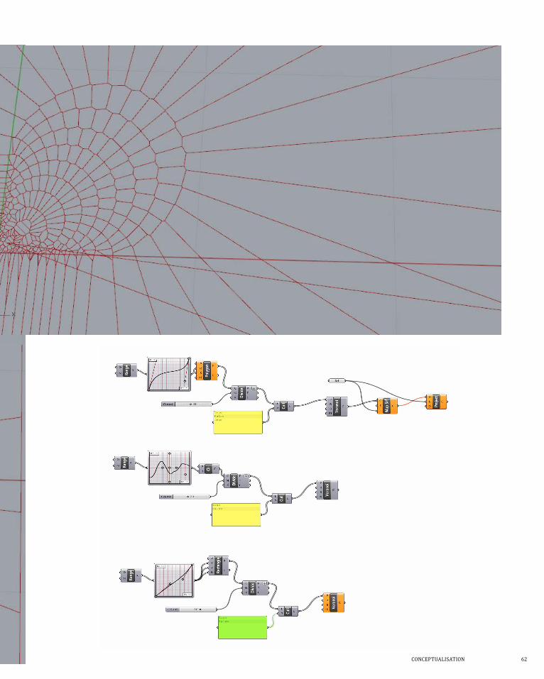
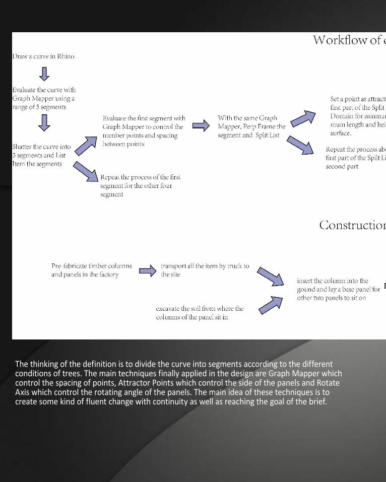
The thinking of the definition is to divide the curve into segments according to the different conditions of trees. The main techniques finally applied in the design are Graph Mapper which control the spacing of points, Attractor Points which control the side of the panels and Rotate Axis which control the rotating angle of the panels. The main idea of these techniques is to create some kind of fluent change with continuity as well as reaching the goal of the brief.
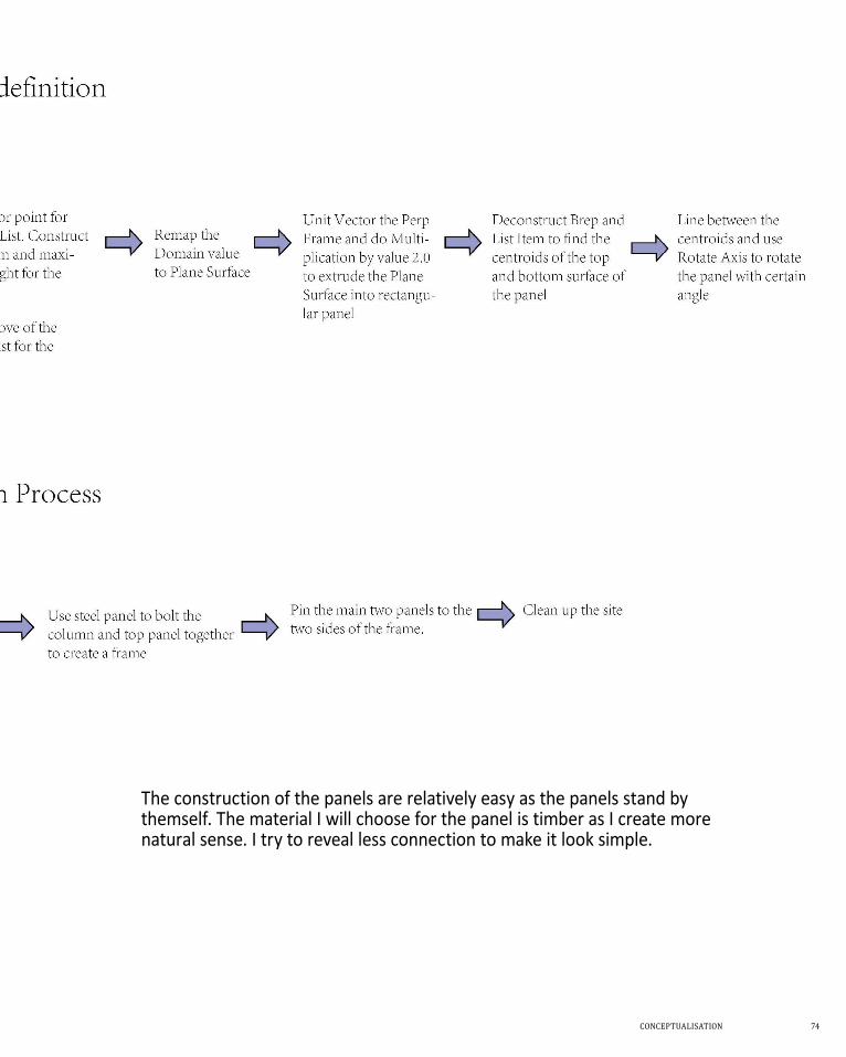
COnCePtUaLisatiOn 74
The construction of the panels are relatively easy as the panels stand by themself. The material I will choose for the panel is timber as I create more natural sense. I try to reveal less connection to make it look simple.
75
COnCePtUaLisatiOn 76
77
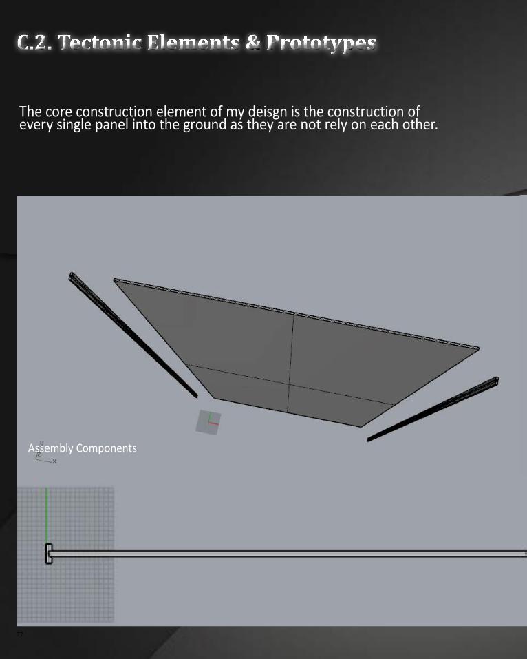
C.2. Tectonic Elements & Prototypes
The core construction element of my deisgn is the construction of every single panel into the ground as they are not rely on each other.
Assembly Components
COnCePtUaLisatiOn 78
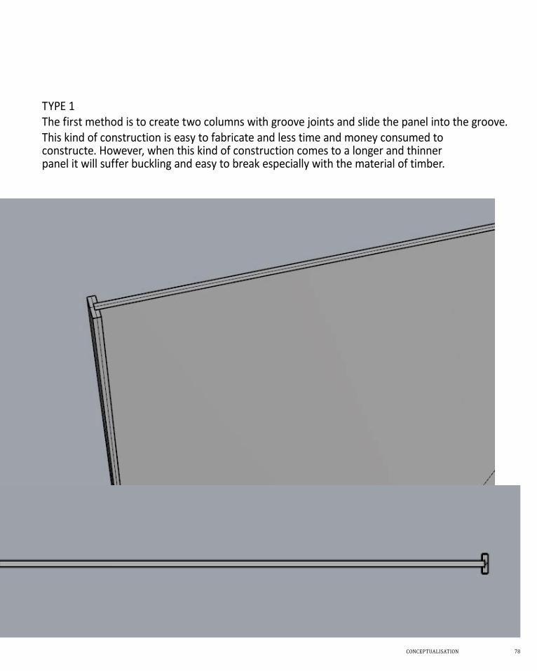
TYPE 1The first method is to create two columns with groove joints and slide the panel into the groove.This kind of construction is easy to fabricate and less time and money consumed to constructe. However, when this kind of construction comes to a longer and thinner panel it will suffer buckling and easy to break especially with the material of timber.
79
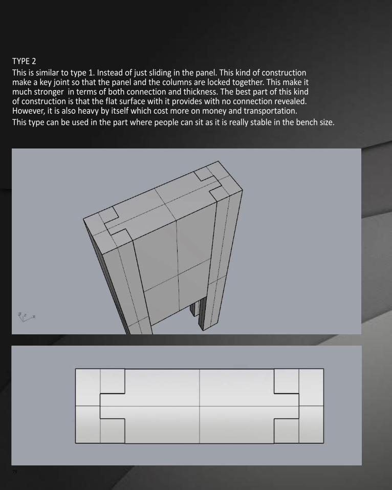
TYPE 2This is similar to type 1. Instead of just sliding in the panel. This kind of construction make a key joint so that the panel and the columns are locked together. This make it much stronger in terms of both connection and thickness. The best part of this kind of construction is that the flat surface with it provides with no connection revealed. However, it is also heavy by itself which cost more on money and transportation.This type can be used in the part where people can sit as it is really stable in the bench size.
COnCePtUaLisatiOn 80
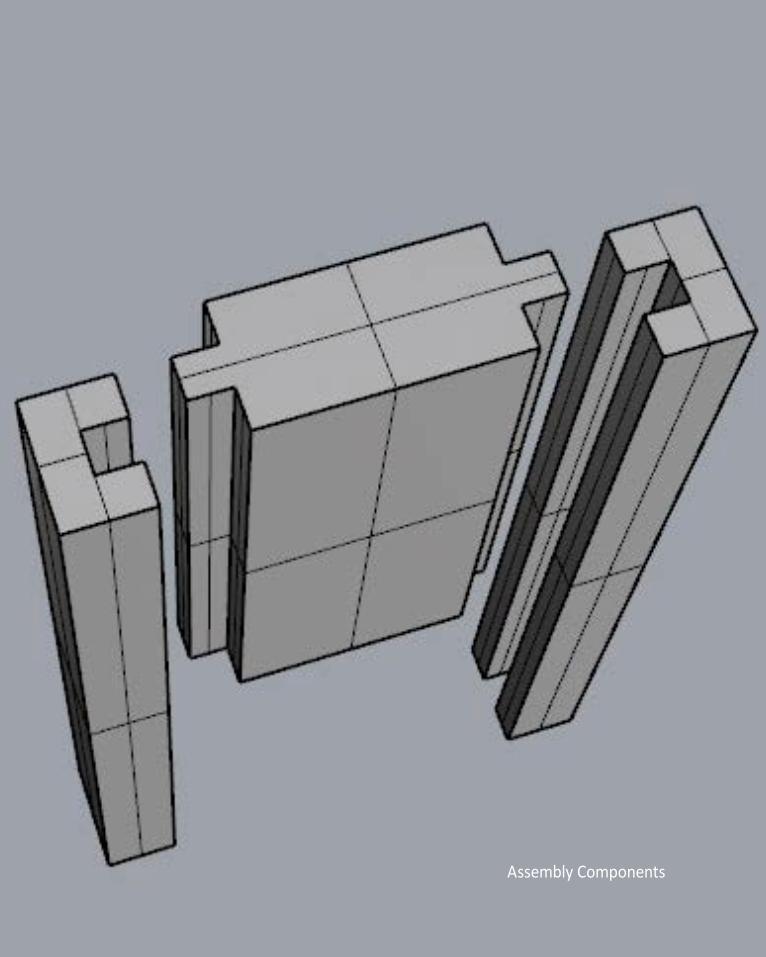
Assembly Components
81
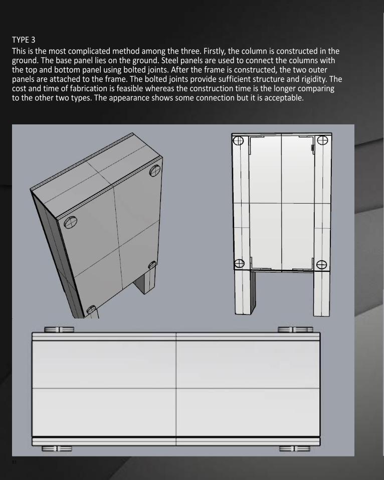
TYPE 3This is the most complicated method among the three. Firstly, the column is constructed in the ground. The base panel lies on the ground. Steel panels are used to connect the columns with the top and bottom panel using bolted joints. After the frame is constructed, the two outer panels are attached to the frame. The bolted joints provide sufficient structure and rigidity. The cost and time of fabrication is feasible whereas the construction time is the longer comparing to the other two types. The appearance shows some connection but it is acceptable.
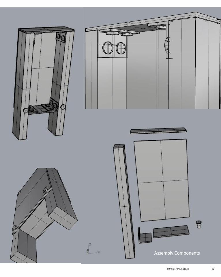
COnCePtUaLisatiOn 82
Assembly Components
83
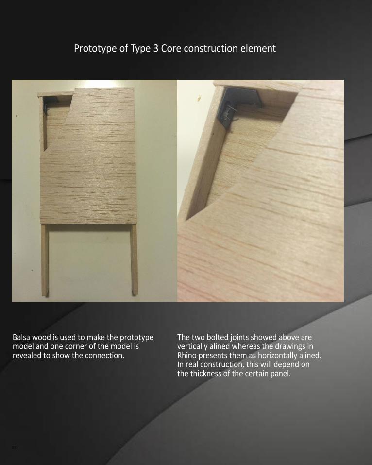
Balsa wood is used to make the prototype model and one corner of the model is revealed to show the connection.
Prototype of Type 3 Core construction element
The two bolted joints showed above are vertically alined whereas the drawings in Rhino presents them as horizontally alined. In real construction, this will depend on the thickness of the certain panel.
COnCePtUaLisatiOn 84
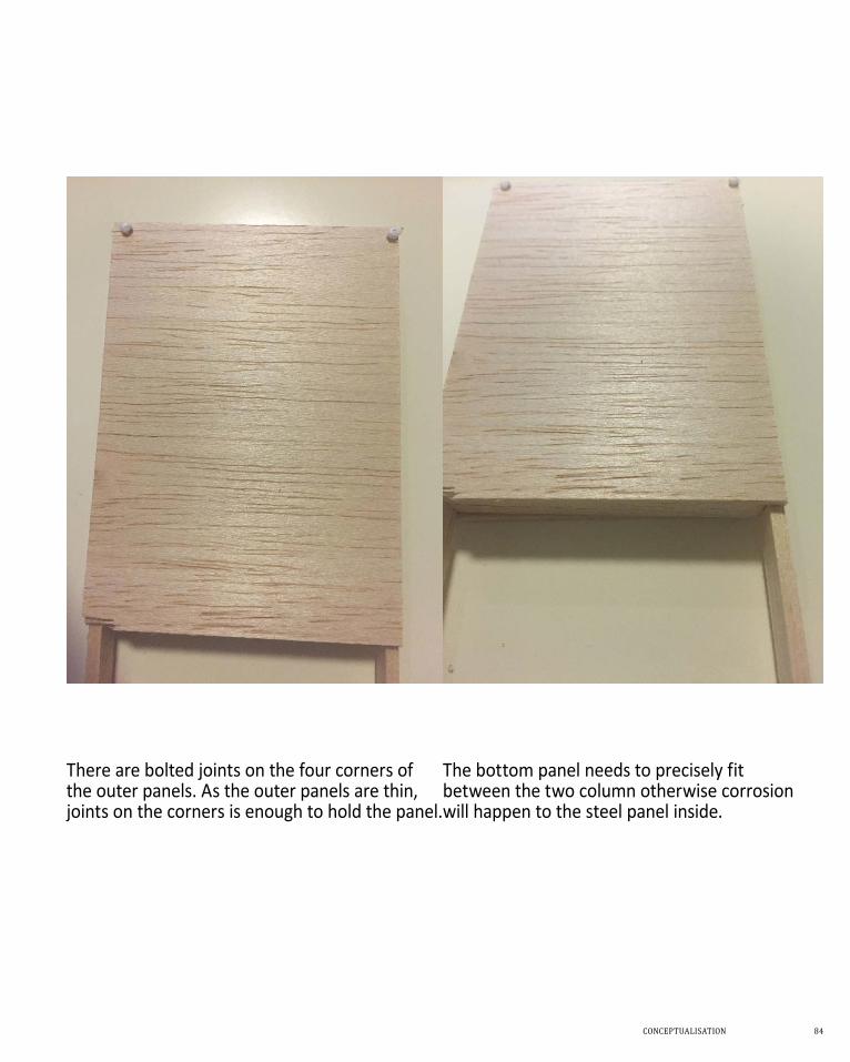
There are bolted joints on the four corners of the outer panels. As the outer panels are thin, joints on the corners is enough to hold the panel.
The bottom panel needs to precisely fit between the two column otherwise corrosion will happen to the steel panel inside.
85
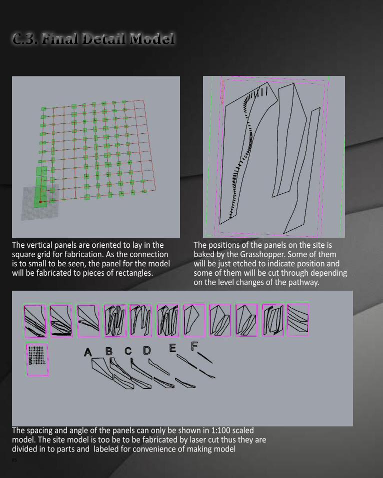
The vertical panels are oriented to lay in the square grid for fabrication. As the connection is to small to be seen, the panel for the model will be fabricated to pieces of rectangles.
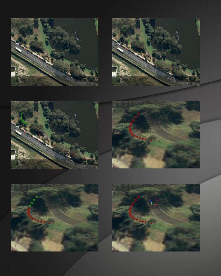
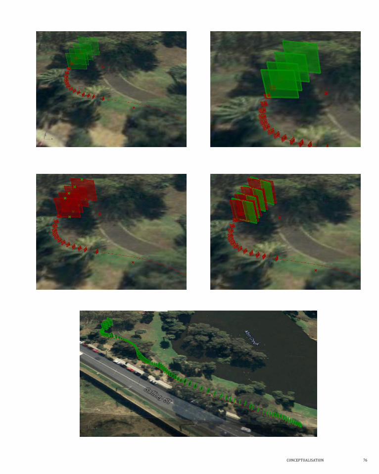
The positions of the panels on the site is baked by the Grasshopper. Some of them will be just etched to indicate position and some of them will be cut through depending on the level changes of the pathway.
The spacing and angle of the panels can only be shown in 1:100 scaled model. The site model is too be to be fabricated by laser cut thus they are divided in to parts and labeled for convenience of making model
COnCePtUaLisatiOn 86
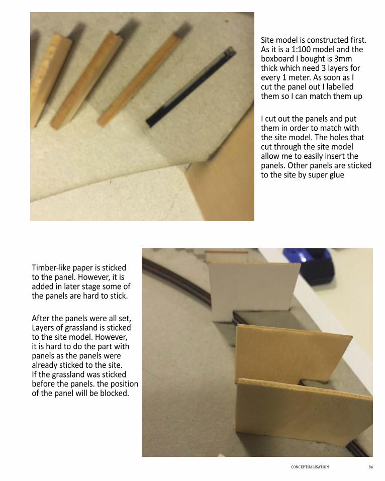
Site model is constructed first. As it is a 1:100 model and the boxboard I bought is 3mm thick which need 3 layers for every 1 meter. As soon as I cut the panel out I labelled them so I can match them up
I cut out the panels and put them in order to match with the site model. The holes that cut through the site model allow me to easily insert the panels. Other panels are sticked to the site by super glue
Timber-like paper is sticked to the panel. However, it is added in later stage some of the panels are hard to stick.
After the panels were all set, Layers of grassland is sticked to the site model. However, it is hard to do the part with panels as the panels were already sticked to the site. If the grassland was sticked before the panels. the position of the panel will be blocked.
87
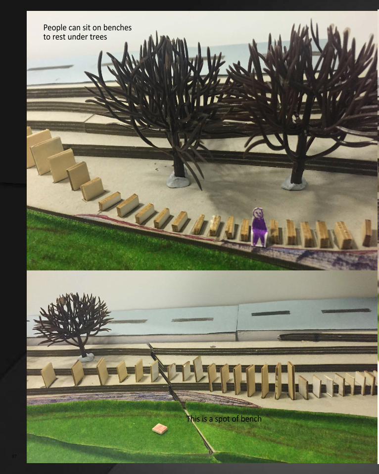
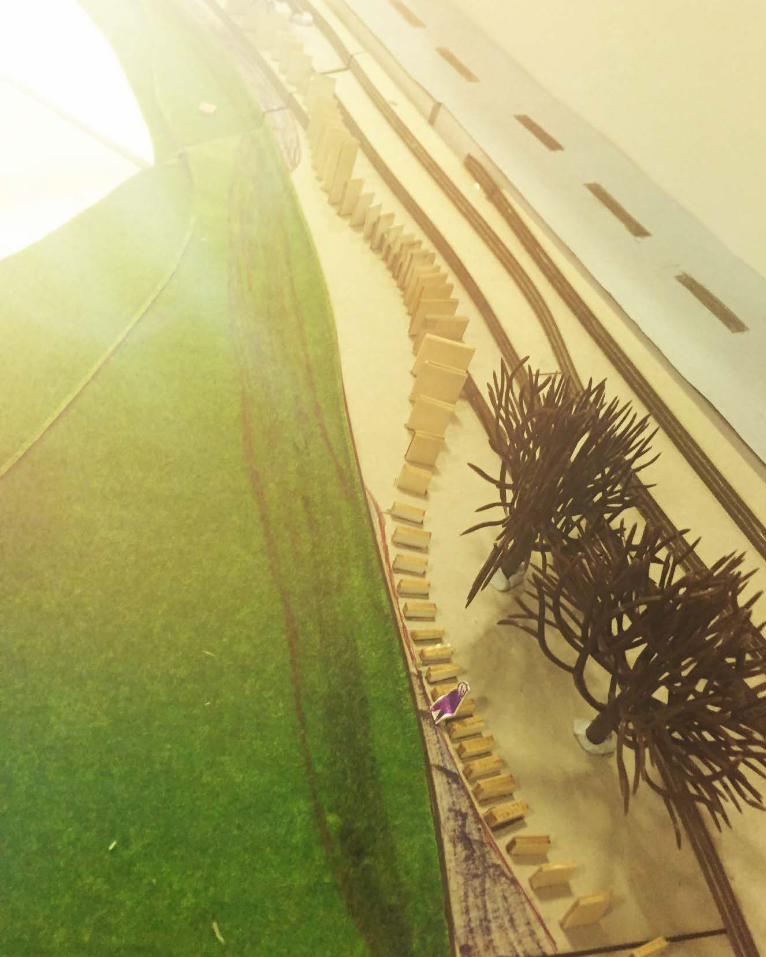
People can sit on benches to rest under trees
This is a spot of bench
COnCePtUaLisatiOn 88
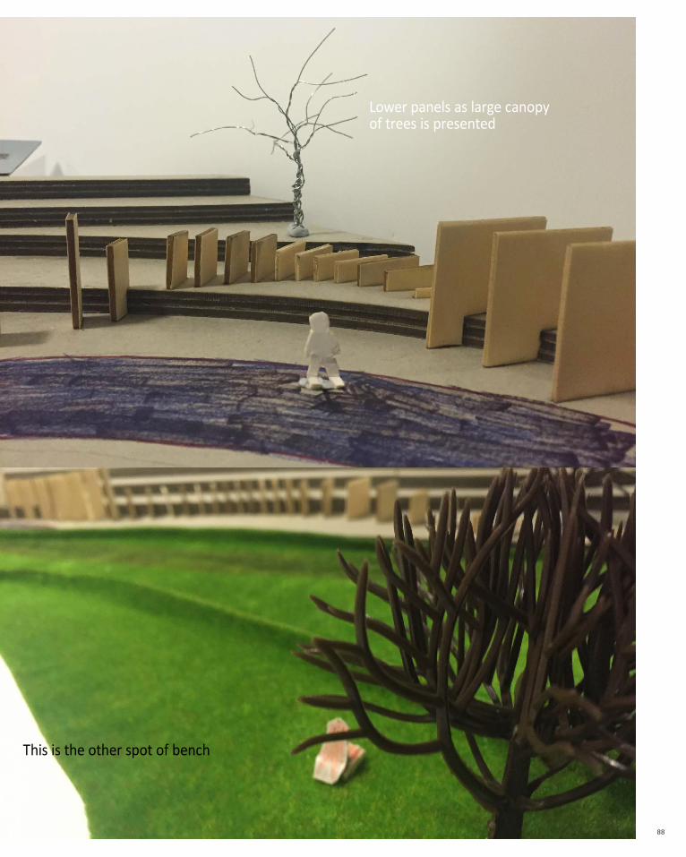
Lower panels as large canopy of trees is presented
This is the other spot of bench
89
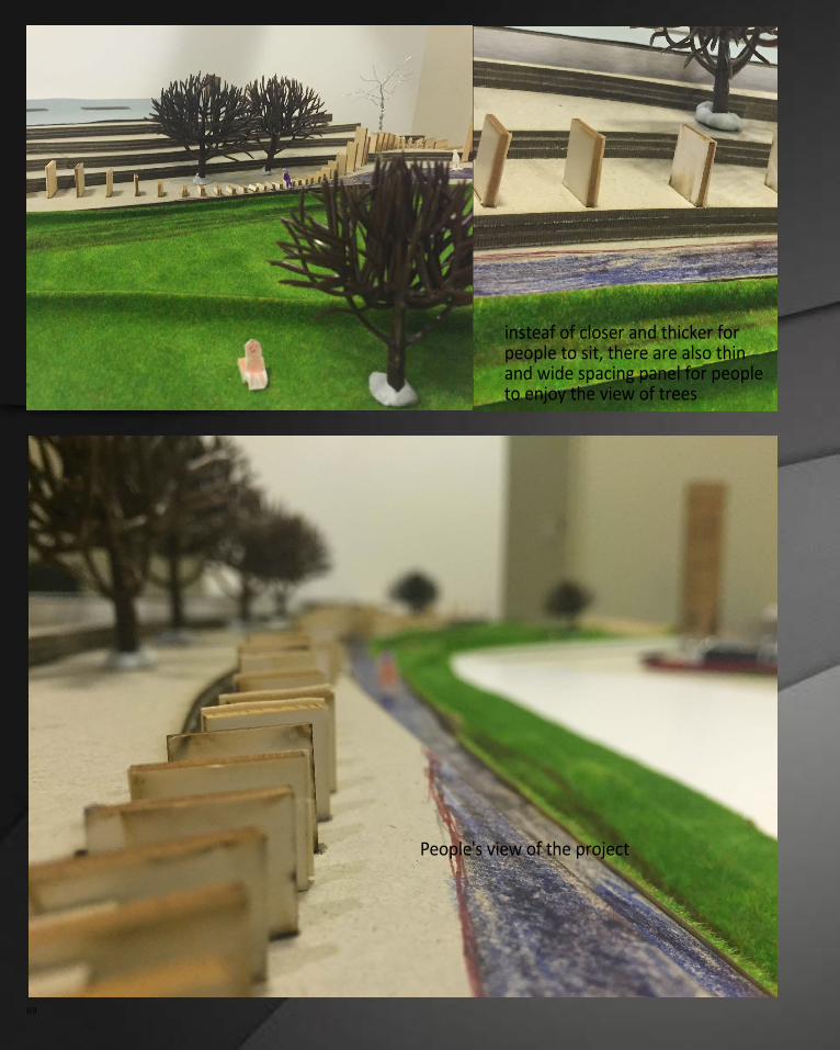
insteaf of closer and thicker for people to sit, there are also thin and wide spacing panel for people to enjoy the view of trees
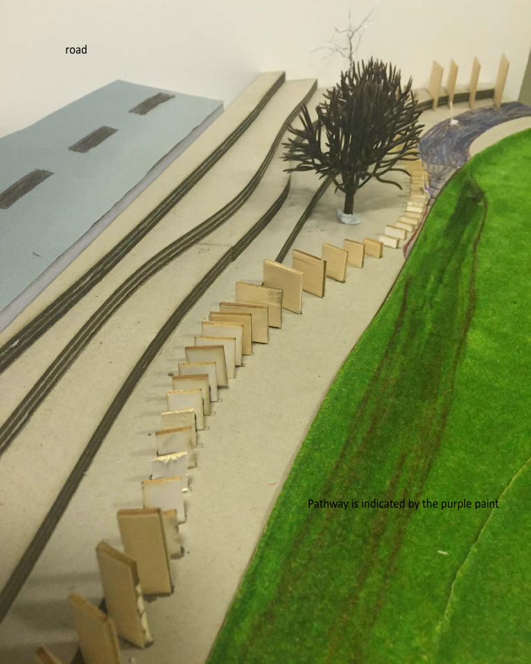
People's view of the project
COnCePtUaLisatiOn 90
Pathway is indicated by the purple paint
road
91
COnCePtUaLisatiOn 92
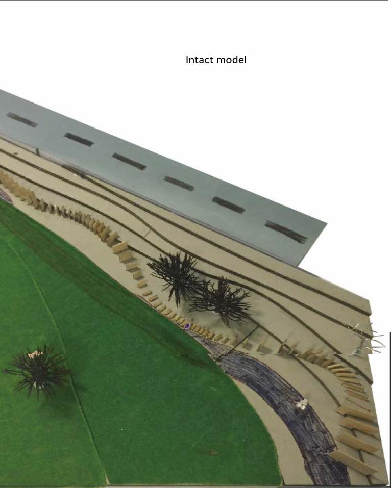
Intact model
93
C.4. Learning Obectives and Outcomes
I had learnt a lot from doing and presenting this project. The feedback from the presentation is that I did not show the pathway, the road and a scaled person in the final model which I tried to modify after the presentation and show in the journal. It is really important to clearly present the idea and kay factors of the project. The lack of these important components induce the lack of understanding for the audience. This is a really crucial thing when doing any assignments which I aware and will improve in study. There was also doubt that whether the panels actually block the view as in some area the contour is even higher than the panel. This is a thing that I did not realise since I did not spend enough time looking at my model. Prototype may be a good choice to make sure that I won't miss this kind of detail. For my design, blocking view is my key concept and I was trying to find a balance between built environment and natural environment. If the panels are too high and visitor are kind of boxed up in the natural environment. The panels are also "built" environment so I thought I should not make them too high. Overall, the project is to shape the view when people walk pass the panels.
For Part C, I had spent a lot of time to work out how I was going to achieve my design concept. One thing I realise is that Grasshopper always tried to "change" and "manipulate" my idea. It was really challenging. However, after I worked out the basic workflow of my definition, I found it interesting to add small components and see how the whole form change. Also I was still struggling with controlling the the form sophistcatedly, but this is how the software teach us to engage and study. For the continuity of the whole project, some panels are not angled to shape the view but to make it look comfortable in the project. It surprised me after I finished the definition of Grasshopper. Even the model looks very simple like putting random size of panels in random angels, it needs to be designed with consideration of site attributes, concept and research field. For this semester's task, I had great improvement in softwares as Rhino, Grasshoper, Indesign and Illustrator which I never learnt before this semester were frequently used. I was usually confused about how to integrate various information of the site, requirement for design and design concept into a design brief but this semester I kind of gradually find a way to think in an architectural way.
It is also challenging and exciting for me as this is my first time doing a laser-cut model. Comparing to the handmade model I had done before, it consumes less time in cutting and is very neat. However, the queue of laser cutting is really long which make me understands that I need to arrange time really well. This subject was really intensive for the whole semester and I had experience from having no idea about parametric design to being able to do parametric design by myself. It was suffering but everything is worthwhile.
COnCePtUaLisatiOn 94