Embed Size (px)
Citation preview

Steel guardrail post W 6 x 8.5 may be substituted for W 6 x 9.3.
compliant.
guardrail transition, and cable terminal anchor are MASH TL-3
2. MGS w-beam guardrail, omitted post, long-span, structure top-mount,
length for MGS w-beam guardrail shall be 6 ft, unless noted otherwise.
guardrail semi-rigid longitudinal barrier system. The standard post
The Midwest Guardrail System (MGS) is a steel or timber post w-beam 1.
GENERAL NOTES:
SHEET NO.
Midwest Guardrail System Assembly, Omitted Post
10
11
12
16
23
2 - 5
6 - 7
Midwest Guardrail System Assembly, Long-Span8 - 9
Midwest Guardrail System Assembly, Structure Top-Mounted Post
Midwest Guardrail System Assembly, Guardrail Transition with Curb
Midwest Guardrail System Assembly, Guardrail Transition without Curb
Midwest Guardrail System Assembly, Guardrail Transition13 - 15
Midwest Guardrail System Assembly, Cable Terminal Anchor System17 - 22
Midwest Guardrail System Assembly, Working Width
SUBJECT
Midwest Guardrail System Assembly Index and General Notes
Midwest Guardrail System Assembly
Midwest Guardrail System Assembly, Height Transition
INDEX
E 601-MGSA-01
INDIANA DEPARTMENT OF TRANSPORTATION
STANDARD DRAWING NO.
DATECHIEF ENGINEER
DATEDESIGN STANDARDS ENGINEER
SEPTEMBER 2018
ASSEMBLY INDEX AND GENERAL NOTES
MIDWEST GUARDRAIL SYSTEM
1
EISGER
DTE
PR
I N
E
S
OF
No.
A
STATE OF
IN AD G
E
E
I
E
R
NR
SNOI A
NL
ELIZ
AB
ETH W. PHIL
LIPS
10200124
/s/ Elizabeth W. Phillips 03/20/18
04/25/18/s/ John Leckie

Shoulder Slope
W-Beam
1'-5" 2'-3 3/4"
Edge of Paved Shoulder
Shoulder Slope
W-Beam
1
Edge of Paved Shoulder
3
Head Nail
16D Double
1
2
(typ.)
Blockout
Composite
Timber or
6" x 8" x 1'-2"
2 Timber or Composite Blockouts
5
5
4
or Timber Post 6" x 8"
Steel Post W 6 x 9
or Timber Post 6" x 8"
Steel Post W 6 x 9
at Face of
Rail
2'-7"
± 1"
at Face of
Rail
2'-7"
± 1"
at Face of
Rail
2'-7"
± 1"
DETAIL FOR ALTERNATE BLOCKOUT DEPTH
Break
Slope
Shoulder
Break
Slope
Shoulder
3'-4"
3'-4"
5
3'-4"
Shoulder Slope
Edge of Paved Shoulder
2
Guardrail
W-Beam
Face of MGS
Guardrail
W-Beam
Face of MGS
Steel Post W 6 x 9
TYPICAL MGS W-BEAM INSTALLATION TYPICAL DOUBLE-FACED MGS W-BEAM INSTALLATION
Guardrail (typ.)
W-Beam
Face of MGS
Blockout
Composite
Timber or
6" x 8" x 1'-2"
T (min.) = 4" (Timber Post)
L = 18", Thread Length
T (min.) = 4" (Steel Post)
L = 10", Thread Length
Depth Recess Both Sides.
Heavy Hex Nut 1"Ø x 1/16"
Guardrail Bolt with
5/8" Ø Button Head
10:1 Max. or Flatter
Slope 20:1 Desirable
2'-0" (min.)
2:1 (m
ax.)
or Flatter
10:1 (max.)
Desirable
Slope 20:1
2'-0" (min.)
2'-0" (min.) 16" (max.)
2:1 (m
ax.)
10:1 (max.) or Flatter
Slope 20:1 Desirable
The post shall not be encased with asphalt, concrete, or riprap.5
the adjacent blockout to limit rotation.
head nail shall be centered at the back of the blockout and driven into
Where two timber blockouts are installed, one 16D galvanized double 4
additional blockouts up to a 16 in. depth.
offset. There is no limit to the number of posts that can have
Blockouts of 12 in. or 16 in. depth may be utilized to increase the post 3
E 601-MGSA-04 for post details.
2 Timber and steel posts shall not be intermixed. See Standard Drawing
E 601-MGSA-23.
than 2 ft, the working width shall be adjusted. See Standard Drawing
Where the distance from back of post to shoulder slope break is less 1
NOTES:
E 601-MGSA-02
INDIANA DEPARTMENT OF TRANSPORTATION
STANDARD DRAWING NO.
DATECHIEF ENGINEER
DATEDESIGN STANDARDS ENGINEER
SEPTEMBER 2018
ASSEMBLY
MIDWEST GUARDRAIL SYSTEM
EISGER
DTE
PR
I N
E
S
OF
No.
A
STATE OF
IN AD G
E
E
I
E
R
NR
SNOI A
NL
ELIZ
AB
ETH W. PHIL
LIPS
10200124
/s/ Elizabeth W. Phillips 03/20/18
/s/ John Leckie 04/25/18
1"
1"
1" (typ.)
W-Beam (Typ.)
Slope 10:1 (
max.)
5/8" Ø Button Head
Guardrail Bolt with
Heavy Hex Nut 1" Ø x 1/16"
Depth Recess Both Sides,
L = 18", Thread Length
T (Min.) = 4"

4 3/8"
6"8"
7 1/2
"
8"
6"
7"
1'-2"
TIMBER OR COMPOSITE
BLOCKOUT WITH STEEL POST
TIMBER BLOCKOUT
WITH TIMBER POST
1'-2"
7"
13/16" Ø Hole
1 1/8" (typ.)
Ø Hole
13/16"
Shoulder Slope
W-Beam
1'-5"
3'-4"
2
1
4
Face of curb
or Timber Post 6"x 8"
Steel Post W 6 x 9
Break
Slope
Shoulder
(typ.)
Blockout
Composite
Timber or
6" x 8" x 1'-2"
at Face of
Rail
2'-7"
± 1"
TYPICAL MGS W-BEAM INSTALLATION AT CURB
Guardrail
W-Beam
Face of MGS
2
Sloping Curb
T (min.) = 4" (Timber Post)
L = 18", Thread Length
T (Min.) = 4" (Steel Post)
L = 10", Thread Length
Depth Recess Both Sides.
Heavy Hex Nut 1"Ø x 1/16"
Guardrail Bolt with
5/8" Ø Button Head
2'-0" (min.)
or Flatter
10:1 (max.)
Slope 20:1 Desirable
2:1 (m
ax.)
The post shall not be encased with asphalt, concrete, or riprap.4
additional blockouts up to a 16 in. depth.
offset. There is no limit to the number of posts that can have
Blockouts of 12 in. or 16 in. depth may be utilized to increase the post 3.
E 601-MGSA-04 for post details.
2 Timber and steel posts shall not be intermixed. See Standard Drawing
E 601-MGSA-23.
than 2 ft, the working width shall be adjusted. See Standard Drawing
Where the distance from back of post to shoulder slope break is less 1
NOTES:
E 601-MGSA-03
INDIANA DEPARTMENT OF TRANSPORTATION
STANDARD DRAWING NO.
DATECHIEF ENGINEER
DATEDESIGN STANDARDS ENGINEER
SEPTEMBER 2018
ASSEMBLY
MIDWEST GUARDRAIL SYSTEM
EISGER
DTE
PR
I N
E
S
OF
No.
A
STATE OF
IN AD G
E
E
I
E
R
NR
SNOI A
NL
ELIZ
AB
ETH W. PHIL
LIPS
10200124
/s/ Elizabeth W. Phillips 03/20/18
/s/ John Leckie 04/25/18
4" (max.)
1"

1"
1"
FRONT VIEW (TIMBER POST)
FRONT VIEW (STEEL POST)
Steel Post
3"3"
6"8"
7"
of Post
of Post
Nail
1-16D Galvanized
Direction of Adjacent Traffic
Direction of Adjacent TrafficDirection of Adjacent Traffic
Direction of Adjacent Traffic
4
STEEL POST &
HOLE PUNCHING DETAIL
(W 6 X 9)
PLAN VIEW (STEEL POST)
PLAN VIEW (TIMBER POST)
Post Bolt Slotted Hole
3/4" x 2 1/2"
Post Bolt Slotted Hole
Face of W-Beam Rail
(typ.)
Post Bolt
Blockout (typ.)
Timber or Composite
(typ.)
W-Beam Rail
(typ.)
Post Bolt
3
TIMBER POST
(6" X 8") NOMINAL
6 x 8 Timber Post
Rail
W-Beam
Face of
No Bolt
(typ.)
Post Bolt
(typ.)
W-Beam Rail
(One permitted)
handling during galvanizing
Optional 1/4" Ø hole for
7"
1 1/8"
1 1/8"
13/16" Ø Holes
1 1/8"
2
Timber Blockout (typ.)
Blockout (typ.)
Timber or Composite
Blockout (typ.)
Timber
blockout
Head embedded in
Hole pattern for posts may be drilled in back flange.6.
additional blockouts up to a 16 in. depth.
offset. There is no limit to the number of posts that can have
Blockouts of 12 in. or 16 in. depth may be utilized to increase the post 5.
blockout and driven into the adjacent post to limit rotation.
galvanized double head nail shall be centered at the back of the
Where a timber post and a timber blockout are installed, one 16D 4
side.
Steel posts shall be installed with bolt holes on approaching traffic 3
Steel guardrail post W 6 x 8.5 may be substituted for W 6 x 9. 2
intermixed.
Timber or steel posts may be used. Timber and steel posts shall not be 1.
NOTES:
E 601-MGSA-04
INDIANA DEPARTMENT OF TRANSPORTATION
STANDARD DRAWING NO.
DATECHIEF ENGINEER
DATEDESIGN STANDARDS ENGINEER
SEPTEMBER 2018
ASSEMBLY
MIDWEST GUARDRAIL SYSTEM
EISGER
DTE
PR
I N
E
S
OF
No.
A
STATE OF
IN AD G
E
E
I
E
R
NR
SNOI A
NL
ELIZ
AB
ETH W. PHIL
LIPS
10200124
/s/ Elizabeth W. Phillips 03/20/18
/s/ John Leckie 04/25/18

ELEVATION VIEW
ELEVATION VIEW
2 22'-7"
2'-7"
2'-7"
at Face of
Rail
at Face of
Rail
at Face of
Rail
12'-6"
Post Spacing
ELEVATION VIEW
Post Spacing
3'-1 1/2"
Post Spacing
3'-1 1/2"
MGS W-BEAM QUARTER POST SPACING, 1'-6 3/4"
MGS W-BEAM HALF POST SPACING, 3'-1 1/2"
MGS W-BEAM STANDARD POST SPACING, 6'-3"
Post Spacing Post Spacing Post Spacing
6'-3"3'-1 1/2"6'-3"
Half Post Spacing
As Needed
MGS Standard Post Spacing MGS Standard Post Spacing
1'-6 3/4"
Quarter Post Spacing
As Needed
Rail Elements
LAPPING PROCEDURE
Direction of Adjacent Traffic
2" 2"
2" 2"8 1/2"
Direction of Adjacent Traffic
12 1/2" Lap
4 1/4"4 1/4"
POST SPLICE DETAIL MID-SPAN SPLICE DETAIL
Blockout (typ.)
Timber or Composite
Button Head Bolt (8 Required)
29/32" x 1 1/8" Slot for 5/8" Ø
Head Bolt
for 5/8" Ø Button
3/4" x 2 1/2" Slot
Bolt (8 Required)
Button Head
Slots for 5/8" Ø
29/32" x 1 1/8"
12 1/2" Lap
on the approach and departure ends of the quarter post spacing.
A minimum of 25 ft of MGS w-beam half post spacing shall be installed 2
Splice locations shall be as shown.1.
NOTES:
E 601-MGSA-05
INDIANA DEPARTMENT OF TRANSPORTATION
STANDARD DRAWING NO.
DATECHIEF ENGINEER
DATEDESIGN STANDARDS ENGINEER
SEPTEMBER 2018
ASSEMBLY
MIDWEST GUARDRAIL SYSTEM
EISGER
DTE
PR
I N
E
S
OF
No.
A
STATE OF
IN AD G
E
E
I
E
R
NR
SNOI A
NL
ELIZ
AB
ETH W. PHIL
LIPS
10200124
/s/ Elizabeth W. Phillips 03/20/18
/s/ John Leckie 04/25/18
Post Spacing
6'-3"
Post Spacing
6'-3"
Post Spacing
6'-3"

ELEVATION VIEW
at Face of
Rail
2'-7"
MGS W-BEAM OMITTED POST
2
Post Spacing (typ.)
12'-6"
Post Spacing
MGS Standard
Post Spacing
MGS Standard
Omitted Post Span
Omitted Post
2
Thrie Beam
MINIMUM DISTANCE BETWEEN OMITTED POST AND MGS GUARDRAIL TRANSITION
PLAN VIEW
Standard Post Spacing
˃ 28'-1 1/2" of MGSı
ı
Asymmetrical W-Beam to Thrie Beam Transition
2 8765431
CRT Posts CRT Posts
Omitted Post Span
MGS Long-Span Out-Out CRT Posts
≥ 37'-6" of MGS Standard Post Spacing
≥ 43'-9"
PLAN VIEW
25'-0" Maximum
MINIMUM DISTANCE BETWEEN OMITTED POST AND MGS LONG-SPAN OUTER CRT POST
10987654321
MINIMUM DISTANCE BETWEEN OMITTED POSTS
≥ 43'-9" of MGS Standard Post Spacing
PLAN VIEW
Omitted Post SpanOmitted Post Span
0
installed adjacent to curb.
An MGS w-beam guardrail run containing an omitted post shall not be 3.
spacing guardrail shall be installed as shown.
Where a post is omitted, a minimum length of MGS standard post 2
A single post may be omitted within an MGS w-beam guardrail run.1.
NOTES:
E 601-MGSA-06
INDIANA DEPARTMENT OF TRANSPORTATION
STANDARD DRAWING NO.
DATECHIEF ENGINEER
DATEDESIGN STANDARDS ENGINEER
SEPTEMBER 2018
ASSEMBLY, OMITTED POST
MIDWEST GUARDRAIL SYSTEM
EISGER
DTE
PR
I N
E
S
OF
No.
A
STATE OF
IN AD G
E
E
I
E
R
NR
SNOI A
NL
ELIZ
AB
ETH W. PHIL
LIPS
10200124
/s/ Elizabeth W. Phillips 03/20/18
/s/ John Leckie 04/25/18
Omitted Post Span
≥ 56'-3"
˃ 34'-4 1/2"
MGS Guardrail Transition

131211102 3 4 5 6 7 8 91
2 3 4 5 6 7 81
14
2 3 4 5 61
≥ 25'-0" of MGS Standard Post Spacing
MINIMUM DISTANCE BETWEEN OMITTED POST AND GUARDRAIL END TREATMENT
MINIMUM DISTANCE BETWEEN OMITTED POST AND MGS CABLE TERMINAL ANCHOR SYSTEM
Omitted Post Span
MINIMUM DISTANCE BETWEEN OMITTED POST AND FLARED MGS W-BEAM
Start of Tangent MGS
Omitted Post Span
56'-3"
Final Post of Cable Terminal Anchor System
installed adjacent to curb.
An MGS w-beam guardrail run containing an omitted post shall not be 3.
spacing guardrail shall be installed as shown.
Where a post is omitted, a minimum length of MGS standard post 2.
See Standard Drawing E 601-MGSA-06
A single post may be omitted within an MGS w-beam guardrail run. 1.
NOTES:
E 601-MGSA-07
INDIANA DEPARTMENT OF TRANSPORTATION
STANDARD DRAWING NO.
DATECHIEF ENGINEER
DATEDESIGN STANDARDS ENGINEER
ASSEMBLY, OMITTED POST
MIDWEST GUARDRAIL SYSTEM
SEPTEMBER 2018
EISGER
DTE
PR
I N
E
S
OF
No.
A
STATE OF
IN AD G
E
E
I
E
R
NR
SNOI A
NL
ELIZ
AB
ETH W. PHIL
LIPS
10200124
/s/ Elizabeth W. Phillips 03/20/18
/s/ John Leckie 04/25/18
Omitted Post Span
PLAN VIEW
PLAN VIEW
PLAN VIEW
≥ 12'-6" of MGS Standard Post SpacingGuardrail End Treatment
≥ 62'-6"
≥ 31'-3"Flared MGS W-Beam

Rail Elements
LAPPING PROCEDURE
Direction of Adjacent Traffic
(3-CRT posts @ 6'-3" spacing)
12'-6"
Span Length, 18'-9"
(3-CRT posts @ 6'-3" spacing)
12'-6"
(3-CRT posts @ 6'-3" spacing)
12'-6"
Span Length, 25'-0"
(3-CRT posts @ 6'-3" spacing)
12'-6"
2'-7"
INSTALLATION TYPE 2
(3 POSTS OMITTED)
INSTALLATION TYPE 1
(2 POSTS OMITTED)
ELEVATION VIEW
ELEVATION VIEW
Out to Out Structure Width
Out to Out Structure Width
2'-7"
MGS Long-Span, Type 2 = 50'-0"
MGS Long-Span, Type 1 = 43'-9"
Minimum Length of MGS Long-Span, Type 1 and MGS W-Beam Guardrail Outside of CRT Posts = 131'-3"
Minimum Length of MGS Long-Span, Type 2 and MGS W-Beam Guardrail Outside of CRT Posts = 150'-0"
W-Beam Guardrail
Minimum MGS
W-Beam Guardrail
Minimum MGS
W-Beam Guardrail
Minimum MGS
W-Beam Guardrail
Minimum MGS
43'-9"
50'-0"
50'-0"
43'-9"
at Face of
Rail
at Face of
Rail
1 2
1 2 1 2
1 2
16'-3" (max.)
22'-6" (max.)
length 12 ft 6 in.
See Standard Drawing E 601-MGSA-06 for one omitted post, span 4.
installed adjacent to curb.
An MGS w-beam guardrail run containing MGS Long-Span shall not be 3.
flared guardrail section.
installed between the outermost CRT post and the beginning of any
A minimum of 62 ft 6 in. of tangent MGS w-beam guardrail shall be 2
anchor, or transition.
may include the length of a guardrail end treatment, cable terminal
approach and departure ends of the outermost CRT posts. This length
A minimum length of MGS w-beam guardrail shall be installed on the 1
NOTES:
E 601-MGSA-08
INDIANA DEPARTMENT OF TRANSPORTATION
STANDARD DRAWING NO.
DATECHIEF ENGINEER
DATEDESIGN STANDARDS ENGINEER
SEPTEMBER 2018
ASSEMBLY, LONG-SPAN
MIDWEST GUARDRAIL SYSTEM
EISGER
DTE
PR
I N
E
S
OF
No.
A
STATE OF
IN AD G
E
E
I
E
R
NR
SNOI A
NL
ELIZ
AB
ETH W. PHIL
LIPS
10200124
/s/ Elizabeth W. Phillips 03/20/18
/s/ John Leckie 04/25/18
12" (min.) 12" (min.)
12" (min.) 12" (min.)
Structure Headwall
Inside Face of 1
STRUCTURE HEADWALL PROJECTION > 2"
Shoulder Slope Break
3'-5" (max.)0" (min.)
at Face of
Rail
2'-7"± 1"
Face of MGS Long-Span
(0" Preferred)Projection > 2"Structure Headwall
Ø Hole
13/16"
TIMBER BLOCKOUT
WITH CRT POST
1'-0"
7"
1'-2"
2'-0" (min.)
8'-0" (min.)
3:1 (max.)
6'-0"
3 1/2" Ø Breakaway Holes
Inside Face of
Structure Headwall
2
STRUCTURE HEADWALL PROJECTION ≤ 2"
Shoulder Slope Break
3'-5" (max.)0" (min.)
10:1 Max. or Flatter
Slope 20:1 Desirable
3:1 Slope
at Face of
Rail
2'-7"± 1"
at Face of
Rail
2'-7"± 1"
Face of MGS Long-Span
Face of MGS Long-Span
(0" Preferred)Projection ≤ 2"Structure Headwall
TYPICAL SECTION AT CRT POST
2'-0" (min.)
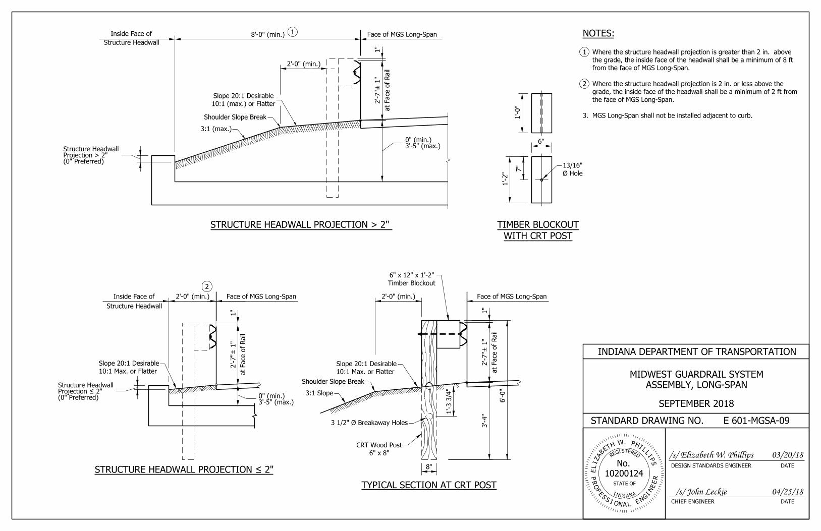
MGS Long-Span shall not be installed adjacent to curb.3.
the face of MGS Long-Span.
grade, the inside face of the headwall shall be a minimum of 2 ft from
Where the structure headwall projection is 2 in. or less above the 2
from the face of MGS Long-Span.
the grade, the inside face of the headwall shall be a minimum of 8 ft
Where the structure headwall projection is greater than 2 in. above 1
NOTES:
E 601-MGSA-09
INDIANA DEPARTMENT OF TRANSPORTATION
STANDARD DRAWING NO.
DATECHIEF ENGINEER
DATEDESIGN STANDARDS ENGINEER
SEPTEMBER 2018
ASSEMBLY, LONG-SPAN
MIDWEST GUARDRAIL SYSTEM
EISGER
DTE
PR
I N
E
S
OF
No.
A
STATE OF
IN AD G
E
E
I
E
R
NR
SNOI A
NL
ELIZ
AB
ETH W. PHIL
LIPS
10200124
/s/ Elizabeth W. Phillips 03/20/18
/s/ John Leckie 04/25/18
1"
6"
10:1 (max.) or Flatter
Slope 20:1 Desirable
10:1 Max. or Flatter
Slope 20:1 Desirable
1'-3 3/4
"
3'-4"
6" x 8"
CRT Wood Post
8"
Timber Blockout
6" x 12" x 1'-2"
2'-0" (min.)
1"
1"

SECTION A-A
Anchor Bolt Base Plate
Outer Structure Edge
4"
1 1/2
"4 1/2
"4 1/2
"1 1/2
"
12"
12"
1 1/2"9"1 1/2"
BASE PLATE AND POST
7/8" Steel Plate, A36
3/16"
1" Ø (typ.)
Outer Structure Edge
4
A
A4" (min.)
8" Blockout
3
3'-5" (max.)9" (min.)
Structure Headwall
Base Plate
Face of MGS W-Beam
Guardrail
6
(0" Preferred)Projection ≤ 2"Structure Headwall
5
TYPICAL SECTION
Spacing
Standard Post
MGS W-Beam
(W 6 x9)
Steel Post
1'-6" (min.)
6" (min.)
10:1 (max.) or Flatter
Slope 20:1 Desirable
E 601-MGSA-10
INDIANA DEPARTMENT OF TRANSPORTATION
STANDARD DRAWING NO.
DATECHIEF ENGINEER
DATEDESIGN STANDARDS ENGINEER
The post shall not be encased with asphalt, concrete, or riprap.6
surfaces shall receive a galvanized coating.
post is field cut, drill holes at appropriate locations. All cut and hole
The top of the post may be field cut to adjust the length. Where the 5
from the outer structure edge.
The center of the anchor bolt shall be installed a minimum of 4 in. 4
Anchoring System.
6 in. The anchor bolt shall be installed using Hilti RE500 Epoxy
with washer and nut, galvanized. The minimum embedment shall be
The anchor bolt shall be 7/8 in. dia. rod, cut off to 8 1/2 in. length, 3
E 601-MGSA-05.
w-beam guardrail post spacing. See Standard Drawing
Top-mounted post shall be spaced in accordance with standard MGS 2.
true-arch structure.
A top-mounted post shall not be installed on an arch-topped or 1.
NOTES:
POST
ASSEMBLY, STRUCTURE TOP-MOUNTED
MIDWEST GUARDRAIL SYSTEM
SEPTEMBER 2018
EISGER
DTE
PR
I N
E
S
OF
No.
A
STATE OF
IN AD G
E
E
I
E
R
NR
SNOI A
NL
ELIZ
AB
ETH W. PHIL
LIPS
10200124
/s/ John Leckie
/s/ Elizabeth W. Phillips 03/20/18
04/25/18
2'-7"
± 1"

1 171615141312111098765432
1'-10 3/4"
17161514131211109871 65432
2'-0"
2'-0"
2
CBA
D
3
5
2'-0"
2'-7"
1
4
C DA B
From 2'-7 3/4" to 2'-7
Top Rail Height Transition
Shoulder Slope Break
MGS GUARDRAIL TRANSITION
ELEVATION VIEW
6'-3"
2 Spa. @ 3'-1 1/2"
6'-3"
4 Spaces @ 3'-1 1/2"
12'-6"
10 Spaces @ 1'-6 3/4"
15'-7 1/2"
1
PLAN VIEW
MGS Guardrail Transition = 40'-7 1/2"
MGS Guardrail Transition = 40'-7 1/2"
MGS Standard Post Spacing, or
Guardrail End Treatment Type OS
MGS Standard Post Spacing, or
Guardrail End Treatment Type OS
E 601-MGSA-11
INDIANA DEPARTMENT OF TRANSPORTATION
STANDARD DRAWING NO.
DATECHIEF ENGINEER
DATEDESIGN STANDARDS ENGINEER
GUARDRAIL TRANSITION WITH CURB
MIDWEST GUARDRAUL SYSTEM ASSEMBLY,
SEPTEMBER 2018
details.
8. See Standard Drawing E 706-CBRT-04 for bridge railing attachment
blockout details and section views.
See Standard Drawing E 601-MGSA-14 through -15 for post and 7.
Components.
See Standard Drawing Series E 601-TBGC for Thrie-Beam Guardrail 6.
See Standard Drawing E 601-MGSA-13 for lap detail.5
of any flared guardrail section.
installed beyond the MGS guardrail transition limits and the beginning
A minimum of 12 ft 6 in. of tangent MGS w-beam guardrail shall be 4
3/4 in. Transition guardrail mounting height down to 2 ft 7 in.
Guardrail mounting height at bridge railing transition shall be 2 ft 7 3
for guardrail transition without curb.
instead of a nested section. See Standard Drawing E 601-MGSA-12
Where curb is not present, a single w-beam section may be installed 2
project beyond the face of w-beam or thrie-beam guardrail.
the length of the transition to post 17. The face of curb shall not
605-CCCG-01 or 605-CCIN-01. Where curb is present it shall extend
Optional 4 in. sloping curb only. See Standard Drawing E 1
NOTES:
EISGER
DTE
PR
I N
E
S
OF
No.
A
STATE OF
IN AD G
E
E
I
E
R
NR
SNOI A
NL
ELIZ
AB
ETH W. PHIL
LIPS
10200124
/s/ Elizabeth W. Phillips
/s/ John Leckie
03/20/18
04/25/18
7 1/4"
12'-6" Two Nested Thrie Beam
Sections (12-Gage)
6'-3" Thrie Beam Section
(12-Gage)
6'-3" Asymmetrical 10-Gage
W-Beam to Thrie-Beam Transition
12'-6" Two Nested W-Beam Sections
(12 Gage) (12-Gage)
W-Beam Sections
11 1/2"

1 171615141312111098765432
1'-10 3/4"
17161514131211109871 65432
2'-0"
2'-0"
CBA
D
2
2'-0"
2'-7"
3
C DA B
Shoulder Slope Break
MGS GUARDRAIL TRANSITION
4
6'-3"
2 Spa. @ 3'-1 1/2"
6'-3"
4 Spaces @ 3'-1 1/2"
12'-6"
10 Spaces @ 1'-6 3/4"
15'-7 1/2"
ELEVATION VIEW
PLAN VIEW
MGS Guardrail Transition = 40'-7 1/2"
MGS Guardrail Transition = 40'-7 1/2"
MGS Standard Post Spacing, or
MGS Standard Post Spacing, or
Guardrail End Treatment Type OS
Guardrail End Treatment Type OS
12'-6" W-Beam Section
E 601-MGSA-12
INDIANA DEPARTMENT OF TRANSPORTATION
STANDARD DRAWING NO.
DATECHIEF ENGINEER
DATEDESIGN STANDARDS ENGINEER
GUARDRAIL TRANSITION WITHOUT CURB
MIDWEST GUARDRAIL SYSTEM ASSEMBLY,
SEPTEMBER 2018
details.
See Standard Drawing E 706-CBRT-04 for bridge railing attachment 7.
blockout details and section views.
See Standard Drawing E 601-MGSA-14 through -15 for post and 6.
Components.
See Standard Drawing Series E 601-TBGC for Thrie-Beam Guardrail 5.
See Standard Drawing E 601-MGSA-13 for lap detail.4
of any flared guardrail section.
installed beyond the MGS guardrail transition limits and the beginning
A minimum of 12 ft 6 in. of tangent MGS w-beam guardrail shall be 3
Transition guardrail mounting height down to 2 ft 7 in.
Guardrail mounting height at bridge railing transition is 2 ft 7 3/4 in. 2
guardrail transition with curb shall apply.
Where a curb is present, details on Standard Drawing E 601-MGSA-11 1.
NOTES:
EISGER
DTE
PR
I N
E
S
OF
No.
A
STATE OF
IN AD G
E
E
I
E
R
NR
SNOI A
NL
ELIZ
AB
ETH W. PHIL
LIPS
10200124
/s/ Elizabeth W. Phillips
/s/ John Leckie
03/20/18
04/25/18
7 1/4"
12'-6" Two Nested Thrie Beam
Sections (12-Gage)
6'-3" Thrie Beam Section
(12-Gage)
6'-3" Asymmetrical 10-Gage
W-Beam to Thrie Beam Transition Top Rail Height Transition
From 2'-7 3/4" to 2'-7
(12-Gage)(12-Gage)
W-Beam Sections
11 1/2"

DETAIL B
Direction of Adjacent Traffic
(Outgoing)
DETAIL A
Direction of Adjacent Traffic
(Incoming)
Terminal Connector
Thrie Beam Rail
Nested Thrie Beam Rail Section
Terminal Connector
Thrie Beam RailNested Thrie Beam Rail Section
Thrie Beam Rail SectionBeam Rail Transition
W-Beam Rail to ThrieRail Section
Nested W-Beam
Bridge
Detail A
Detail B Detail A
Detail B
Transition (typ.)
Concrete Bridge Railing
GUARDRAIL TRANSITION PLAN VIEW
LAP DETAILS AT BRIDGE RAILING TRANSITION PLAN VIEW
Thrie Beam Rail Section
Beam Rail Transition
W-Beam Rail to Thrie
Concrete Bridge Rail (typ.)
Railing Transition
Concrete Bridge
Rail Section
Nested W-Beam
Railing Transition
Concrete Bridge
E 601-MGSA-13
INDIANA DEPARTMENT OF TRANSPORTATION
STANDARD DRAWING NO.
DATECHIEF ENGINEER
DATEDESIGN STANDARDS ENGINEER
ASSEMBLY, GUARDRAIL TRANSITION
MIDWEST GUARDRAIL SYSTEM
SEPTEMBER 2018
EISGER
DTE
PR
I N
E
S
OF
No.
A
STATE OF
IN AD G
E
E
I
E
R
NR
SNOI A
NL
ELIZ
AB
ETH W. PHIL
LIPS
10200124
/s/ Elizabeth W. Phillips
/s/ John Leckie
03/20/18
04/25/18

1'-7"
6"
7 1/8
"7 5/8
"
4 1/4
"
1'-0"
7 1/8
"7 5/8
"
1"
3 15/16"
1"
5 7/8"
4 3/8"
2
11 1/2
"
6"
7'-0"
Posts 1-6
6'-0"
Posts 7-1
2
(typ.)
13/16" Ø 1 7/8"
(typ.)
13/16" Ø
1 1/8"
Galvanizing)
(Optional for
1/4" Ø
1'-0"
BreakShoulder Slope
2'-7 3/4
"
2'-0" (min.)
or Flatter10:1 (max.)
Slope 20:1 Desirable
4'- 4" (min.)
1'-0"
3'- 4"
Min.
BreakShoulder Slope
2'-7 3/4
"
2'-0" (min.)
or Flatter10:1 (max.)
Slope 20:1 Desirable
1'-0"
BreakShoulder Slope
2'-7 3/4
"
or Flatter10:1 (max.)
Slope 20:1 Desirable
3'- 4" (min.)
2'-0" (min.)
INDIANA DEPARTMENT OF TRANSPORTATION
STANDARD DRAWING NO.
DATECHIEF ENGINEER
DATEDESIGN STANDARDS ENGINEER
sections.
See Standard Drawing E 601-MGSA-11 or -12 for post numbers and 4.
flange.
Hole pattern for post numbers 1 through 12 may be drilled in back 3.
transition.
Timber posts shall not be used within the limits of the MGS guardrail 2
All holes drilled or punched to 13/16 in. dia.1.
NOTES:
ASSEMBLY, GUARDRAIL TRANSITION
MIDWEST GUARDRAIL SYSTEM
SEPTEMBER 2018
E601-MGSA-14
/s/ Elizabeth W. Phillips
/s/ John Leckie 04/25/18
03/20/18EISGER
DTE
PR
I N
E
S
OF
No.
A
STATE OF
IN AD G
E
E
I
E
R
NR
SNOI A
NL
ELIZ
AB
ETH W. PHIL
LIPS
10200124
1"
1"
1"
FRONT VIEWTOP VIEW
TOP VIEW
SIDE VIEW FRONT VIEW
W 6 x 9 POST DETAILS
BLOCKOUT POSTS 1-12
(TIMBER)
(typ.)
Post Bolts
W 6 x 9 Post
Shoulder
Thrie-Beam
Face of
Rail
POSTS 1-6
SECTION A-A
2:1 (m
ax.)
Slope
(typ.)
Post Bolts
W 6 x 9 Post
Shoulder
Thrie-Beam
Face of
Rail
POSTS 7-11
SECTION B-B
2:1 (m
ax.)
Slope
(typ.)
Post Bolt
W 6 x 9 Post
Shoulder
Face of
Rail
SECTION C-C
TransitionThrie-BeamW-Beam to
POST 12
No Bolt
2:1 (m
ax.)
Slope

1"
3 15/16"
1"
5 7/8"
SIDE VIEW FRONT VIEW
6'-0"
Face of
Rail
W 6 x 9 Post
(typ.)
Post Bolt
TOP VIEW
6"
TOP VIEW FRONT VIEW
POSTS 13-17
2'-7"
2'-0" Min. 1'-0"
2
11 1/2
"
1'-0"
6"
4 3/8"
SECTION D-D
POSTS 13-17
3'- 4"
Min.
W-Beam
BreakShoulder Slope
7"
1'-2"
7"
(typ.)
13/16" Ø
13/16" Ø
1 7/8"
1 1/8"
Galvanizing)
(Optional for
1/4" Ø
BLOCKOUT POSTS 13-17
(TIMBER)
Shoulder
or Flatter10:1 (max.)
Slope 20:1 Desirable
E 601-MGSA-15
INDIANA DEPARTMENT OF TRANSPORTATION
STANDARD DRAWING NO.
DATECHIEF ENGINEER
DATEDESIGN STANDARDS ENGINEER
2
sections.
See Standard Drawing E 601-MGSA-11 or -12 for post numbers and 4.
flange.
Hole pattern for post numbers 13 through 17 may be drilled in back 3.
transition.
Timber posts shall not be used within the limits of the MGS guardrail
All holes drilled or punched to 13/16 in. dia.1.
NOTES:
ASSEMBLY, GUARDRAIL TRANSITION
MIDWEST GUARDRAIL SYSTEM
SEPTEMBER 2018
EISGER
DTE
PR
I N
E
S
OF
No.
A
STATE OF
IN AD G
E
E
I
E
R
NR
SNOI A
NL
ELIZ
AB
ETH W. PHIL
LIPS
10200124
/s/ Elizabeth W. Phillips
/s/ John Leckie
03/20/18
04/25/18
1"
2:1 (m
ax.)
Slope

2'-4 3/4
" to
Top of Post
Top of Post
2'-8"
Top of
Rail
2'-7"
3'-1 1/2"3'-1 1/2"6'-3"
13/1
6"
MGS Standard
1 5/8
"
2 7/1
6"
3 1/4
"
Existing W-Beam
Guardrail
Transition Top of Rail Height 2'-3 3/4" to 2'-7"
2 Panels @ 12'-6" = 25'-0"
2'-7" Height
1 Panel @ 12'-6"
2'-7"
MGS W-Beam Guardrail Height Transition = 37'-6"
2'-3 3/4
" to
Top of
Rail
Post Spacing
E 601-MGSA-16
INDIANA DEPARTMENT OF TRANSPORTATION
STANDARD DRAWING NO.
DATECHIEF ENGINEER
DATEDESIGN STANDARDS ENGINEER
shall be cut and repositioned behind the flange.
Where rub-rail is present on existing w-beam guardrail, the channel 1.
NOTES:
HEIGHT TRANSITION
MIDWEST GUARDRAIL ASSEMBLY,
SEPTEMBER 2018
EISGER
DTE
PR
I N
E
S
OF
No.
A
STATE OF
IN AD G
E
E
I
E
R
NR
SNOI A
NL
ELIZ
AB
ETH W. PHIL
LIPS
10200124
/s/ Elizabeth W. Phillips
/s/ John Leckie
03/20/18
04/25/18
ELEVATION VIEW

6'-3"
2'-7"
W-Beam Rail Element
Strut (Channel Section)
See Detail B
See Detail A
Direction of Adjacent Traffic
Guardrail Anchor Bracket
BCT Anchor Cable
BCT Anchor Cable
Guardrail Anchor BracketBCT Timber Post
BCT Timber Post
Galvanized Steel Foundation TubeGalvanized Steel Foundation Tube
Curved Terminal End
Shoulder Slope Break
2
33
3
22
4
5
5
6
6
7
Post A Post B
See Detail B
3
3'-1 1/2"
ELEVATION VIEW
PLAN VIEW
both sides (typ.)
bolt with heavy nut recessed
5/8"Ø x 1 1/4" button head
bolt with hex nuts (typ.)
5/8"Ø x 1 1/2" hex head
head & nut
w/ round washers under
5/8"Ø x 10" bolt and nut
round washer
1"Ø hex nut with
MGS Cable Terminal Anchor System = 12'-6"
head and round washer under nut. (typ.)
(min.)= 4". Use rectangular washer under
hex nut recessed both sides. L = 10' T
5/8" button head guardrail bolt w/heavy
Slope 20:1
Desirable
10:1 (max.)
or Flatter
2'-0" (min.)
E 601-MGSA-17
INDIANA DEPARTMENT OF TRANSPORTATION
STANDARD DRAWING NO.
DATECHIEF ENGINEER
DATEDESIGN STANDARDS ENGINEER
See Standard Drawing E 601-WBGC-01 for curved terminal end details.7
details.
See Standard Drawing E 601-MGSA-22 for guardrail anchor bracket 6
details.
See Standard Drawing E 601-MGSA-21 for BCT anchor cable assembly 5
See Standard Drawing E 601-MGSA-20 for strut details.4
foundation tube details.
See Standard Drawing E 601-MGSA-19 for BCT timber post and steel 3
See Standard Drawing E 601-MGSA-18 for Details A and B.2
oncoming traffic.
outgoing end of an MGS w-beam guardrail run not exposed to
The MGS cable terminal anchor system shall only be used at the 1.
NOTES:
ASSEMBLY, CABLE TERMINAL ANCHOR SYSTEM
MIDWEST GUARDRAIL SYSTEM
SEPTEMBER 2018
EISGER
DTE
PR
I N
E
S
OF
No.
A
STATE OF
IN AD G
E
E
I
E
R
NR
SNOI A
NL
ELIZ
AB
ETH W. PHIL
LIPS
10200124
/s/ Elizabeth W. Phillips
/s/ John Leckie
03/20/18
04/25/18
6'-3" to next post

Strut (Channel Section)
BCT Bearing Plate BCT Post Sleeve
head & nut
w/ round washer under
7/8"Ø x 8" bolt and nut
head & nut
w/ round washers under
5/8"Ø x 10" bolt and nut
BCT Timber PostBCT Timber Post
BCT Anchor Cable Assembly
Foundation Tube
Galvanized Steel
Foundation Tube
Galvanized Steel
DETAIL A DETAIL B
3"
2
1 1
E 601-MGSA-18
INDIANA DEPARTMENT OF TRANSPORTATION
STANDARD DRAWING NO.
DATECHIEF ENGINEER
DATEDESIGN STANDARDS ENGINEER
details.
See Standard Drawing E 601-MGSA-21 for BCT anchor cable assembly 2
bearing plate details.
See Standard Drawing E 601-MGSA-21 for BCT post sleeve and BCT 1
NOTES:
CABLE TERMINAL ANCHOR SYSTEM
MIDWEST GUARDRAIL SYSTEM ASSEMBLY,
SEPTEMBER 2018
EISGER
DTE
PR
I N
E
S
OF
No.
A
STATE OF
IN AD G
E
E
I
E
R
NR
SNOI A
NL
ELIZ
AB
ETH W. PHIL
LIPS
10200124
/s/ Elizabeth W. Phillips
/s/ John Leckie
03/20/18
04/25/18
2"
No
minal

1"
Attach BCT Post
3/4" Ø Hole to
T 8" x 6" x 3/16"
FRONT SIDE
SIDE FRONT
GALVANIZED STEEL
FOUNDATION TUBE
BCT TIMBER POST
1'-5"
8"2"
3'-10"
7/8
"
2 1/2
"
5 1/2"
2 3/4"
7 1/2
"
3 3/4
"
7 1/8
"1'-11 7/8
"
for Post A Only
2 1/2" Ø Hole
7/8" Hole
6'-0"
Slot
13/16" x 2 3/4"
3"
to Hold BCT Post
7/8" Ø x 8" Bolt
1" Ø Hole to Hold
4"
E 601-MGSA-19
INDIANA DEPARTMENT OF TRANSPORTATION
STANDARD DRAWING NO.
DATECHIEF ENGINEER
DATEDESIGN STANDARDS ENGINEER
CABLE TERMINAL ANCHOR SYSTEM
MIDWEST GUARDRAIL SYSTEM ASSEMBLY,
SEPTEMBER 2018
EISGER
DTE
PR
I N
E
S
OF
No.
A
STATE OF
IN AD G
E
E
I
E
R
NR
SNOI A
NL
ELIZ
AB
ETH W. PHIL
LIPS
10200124
/s/ Elizabeth W. Phillips
/s/ John Leckie
03/20/18
04/25/18
6"
1'-5 1/2
"
6"

5'-7"
3/16"
5 1/2
"
7/8" x 2" Slot
4"
YokeStrut
Yoke
6"
8 1/8"
3/16"
3/16"STRUT AND YOKE ASSEMBLY
STRUT DETAILS
YOKE DETAILS
(2 Required)
1"
2" on C 6 x 8.2
2" on C 6 x 8.2
C 6 x 8.2 or Bent Plate 6" x 3" x 10 Gauge
3" on Bent Plate
3" on Bent Plate
1/2"R(typ.)
(typ.)
E 601-MGSA-20
INDIANA DEPARTMENT OF TRANSPORTATION
STANDARD DRAWING NO.
DATECHIEF ENGINEER
DATEDESIGN STANDARDS ENGINEER
CABLE TERMINAL ANCHOR SYSTEM
MIDWEST GUARDRAIL ASSEMBLY,
SEPTEMBER 2018
EISGER
DTE
PR
I N
E
S
OF
No.
A
STATE OF
IN AD G
E
E
I
E
R
NR
SNOI A
NL
ELIZ
AB
ETH W. PHIL
LIPS
10200124
/s/ Elizabeth W. Phillips
/s/ John Leckie
03/20/18
04/25/18
5/16"R

8"
8"
6"
5"
4"
1 1/8" Ø Hole
2"
7"
3/8"
3/8"
4'-2"5"3"7" 7"3"5"
6'-8"
3/4"Ø (6 x 19) Galvanized Cable
Threads (Both Sides)
1" Ø x 1/8" Pitch
BCT POST SLEEVE BCT BEARING PLATE
BCT ANCHOR CABLE ASSEMBLY
with Round Washer
1" Ø Hex Nut
with Round Washer
1" Ø Hex Nut
Entire Length)
and Stud (Stud Threaded
Standard Swaged Fitting
Cable to be Swage-Connected
1 5/8
"
1 1/4
"
2 3/8
" O.D.
INDIANA DEPARTMENT OF TRANSPORTATION
STANDARD DRAWING NO.
DATECHIEF ENGINEER
DATEDESIGN STANDARDS ENGINEER
CABLE TERMINAL ANCHOR SYSTEM
MIDWEST GUARDRAIL SYSTEM ASSEMBLY,
SEPTEMBER 2018
E601-MGSA-21
EISGER
DTE
PR
I N
E
S
OF
No.
A
STATE OF
IN AD G
E
E
I
E
R
NR
SNOI A
NL
ELIZ
AB
ETH W. PHIL
LIPS
10200124
/s/ Elizabeth W. Phillips
/s/ John Leckie
03/20/18
04/25/18

2"4"4"4"2"
1'-4"
5 1/2"
2 3/4"
3"
3/8" 1 3/8"1 1/2
"
1 3/4
"2"
Bracket
End Plate
3/8"
3 3/8"2 3/8"
3/1
6"
2.5̊
35°
1/4"
3/4" Ø Holes
3/8" R (Typ.)
1" R (Typ.)
1 1/8" Ø Hole
END PLATE
BRACKET
GUARDRAIL ANCHOR BRACKET
Bent Plate 1'-4" x 1'-0 5/8" x 3/16"
Weld End Plate to Bracket
E 601-MGSA-22
INDIANA DEPARTMENT OF TRANSPORTATION
STANDARD DRAWING NO.
DATECHIEF ENGINEER
DATEDESIGN STANDARDS ENGINEER
CABLE TERMINAL ANCHOR SYSTEM
MIDWEST GUARDRAIL SYSTEM ASSEMBLY,
SEPTEMBER 2018
EISGER
DTE
PR
I N
E
S
OF
No.
A
STATE OF
IN AD G
E
E
I
E
R
NR
SNOI A
NL
ELIZ
AB
ETH W. PHIL
LIPS
10200124
/s/ Elizabeth W. Phillips
/s/ John Leckie
03/20/18
04/25/18
2 3/4" 1 5/8"
8" Blockout
Guardrail Type
MGS W-Beam Standard
8" Blockout
MGS W-Beam Standard
Face of MGS W-Beam
Guardrail
Face of MGS W-Beam
Guardrail
2'-7"
± 1"
2'-7"
± 1"
MGS W-Beam Standard
w/Omitted Post
MGS W-Beam Half
Post Spacing
MGS W-Beam Quarter
Post Spacing
MGS Structure
Top-Mount Post
at Face of
Rail
at Face of
Rail
Working Width
Working Width
slope break (D)of post and shoulder Distance between back
guardrail
object behind the
Nearest face of
Headwall
Structure
guardrail
object behind the
Nearest face of
Shoulder Slope Break
MGS Long-Span
D
MGS Structure Top-Mounted Post
Post Spacing Working Width
2 ft
2 ft
6'-3"
6'-3"
6'-3"
3'-1 1/2"
6'-3"
2 ft
2 ft
5.0 ft
5.0 ft
6.5 ft
4.5 ft
4.0 ft
4.2 ft
D
< 2 ft
1.5 ft 3
Varies 8.0 ft4
1'-6 3/4"
3
(0"
Preferred)
Project
> 2"
Structure H
ead
wall
E 601-MGSA-23
INDIANA DEPARTMENT OF TRANSPORTATION
STANDARD DRAWING NO.
DATECHIEF ENGINEER
DATEDESIGN STANDARDS ENGINEER
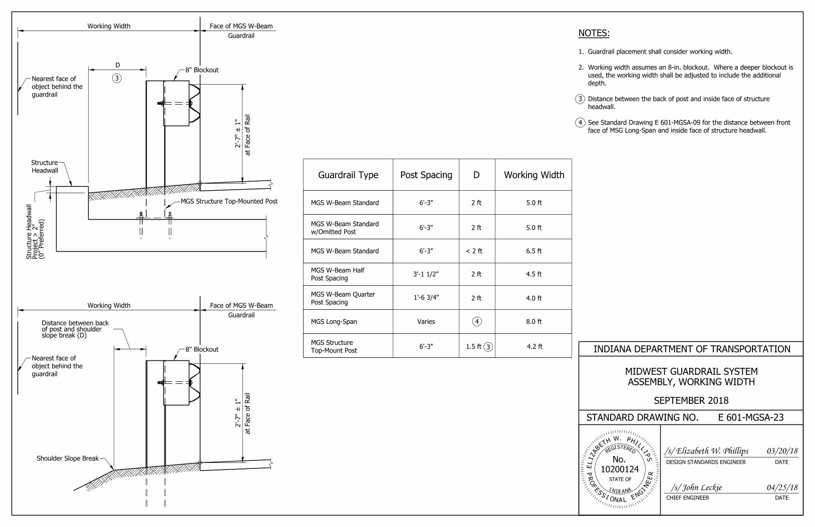
face of MSG Long-Span and inside face of structure headwall.
See Standard Drawing E 601-MGSA-09 for the distance between front 4
headwall.
Distance between the back of post and inside face of structure 3
depth.
used, the working width shall be adjusted to include the additional
Working width assumes an 8-in. blockout. Where a deeper blockout is 2.
Guardrail placement shall consider working width.1.
NOTES:
ASSEMBLY, WORKING WIDTH
MIDWEST GUARDRAIL SYSTEM
SEPTEMBER 2018
EISGER
DTE
PR
I N
E
S
OF
No.
A
STATE OF
IN AD G
E
E
I
E
R
NR
SNOI A
NL
ELIZ
AB
ETH W. PHIL
LIPS
10200124
/s/ Elizabeth W. Phillips
/s/ John Leckie
03/20/18
04/25/18