Embed Size (px)
Citation preview

7/27/2019 Sheet Metal HO
http://slidepdf.com/reader/full/sheet-metal-ho 1/5
1
Sheet Metal Design inSolidworks
CAE Assignment #5
July 26, 2007
Sara-Jane Squires, Meghan Couves, Bethan Martin and Mary Fowler
Summary
Introduction
Solidworks Features
Toolbox
Add it ional Features
Practical Applications
Conclusion
Sheet Metal Introduction
z Could draw part and extrude or revolve like in most of the projects to date.
z Sheet metal application more powerful.
z Parts have constant thickness.
z Do not need to mess with feature order to get part towork right.
z Old way very order dependent
z Easy to change sketch of previously created flange.
z Automatically takes care of bend allowances
K FactorsK Factors
z A si ngl e valu e whi ch c an be u sed t o rep resen t ho wsheet metal bends fold/unfold over a wide range of geometric parameters
z If your model is being used for manufacturing, setK<0.5
z If not it will not unfold correctly for most bendingscenarios.
z Use 0.42 or 0.33
Bend Type Common “K” facto
Large Radius Bend (radius 4
larger than stock) 0.5
Rotary Bender (like “Ready
bender”) 0.43
Vee Bend 0.42
90 Deg. Wipe - No Set Radius 0.38
90 Deg. Wipe Plus Set Radius 0.33
Bend AllowancesBend Allowance
z How much material isneeded between two panelsto accommodate a givenbend.
z Solidworks automaticallytakes this into account whencreating flat drawings from3D.
Solidworks Features
Base Flange – Creates sheet metal part
Edge – Adds a wall to an edge
Miter – Adds a series of flanges to an edge (or edges)
Hem – Curls the edge of a sheet metal piece
Sketched Bend – Adds a bend to a selected sketch
Closed corner – Extends the face of a sheet metal part

7/27/2019 Sheet Metal HO
http://slidepdf.com/reader/full/sheet-metal-ho 2/5
2
Solidworks Features (Cont’d)
Jog – Adds 2 bends from a sketched line
Break corner – cuts material from a face or edge
Unfold – unfolds bends in a sheet metal part
Fold – folds flattened bends in a sheet metal part
Flatten – shows the flattened pattern of a part
Rip – creates a gap between two edges
Sheet Metal Toolbox
Bottom
1) Add Sheet Metal Toolbar (Right
click; add Sheet Metal)2) Choose icon labeled Base
Flange
3) In the base flange window
select Front View
4) Create a rectangle withdimensions 9.89” and 18”
5) Exit sketch and the base flange6) Properties window will appear
on the left hand side of the
screen.
7) Under Sheet metal
parameters set T1 value to 0.1
inches
Bends:
1) Select the Edge Flange
icon
2) Select edge to be bent (18”
long edge)
3) Drag the bend direction up
4) Set D value under flangelength to 1 inch.
Cover
1) Create a “Base Flange”
drawing in the front plane.
2) Exit Sketch
3) Make to desired thickness.
End Pieces
z Create a “Base Flange”drawing in the front plane
z Exit sketch
z Both ends need to be edge
flanged
z Select “Edge Flange” from thetoolbar
z Selecting one edge at a time,
drag each arrow out (all in the
same direction.)
z Pull these edge flanges out 1”
z Repeat until the entire end
piece is flanged.
Sides
z Create a “Base Flange”drawing of the side of 18” X 6”.
z Exit sketch and on the lefthand side ensure that T1 is
again set to 0.1 inches
NOTE: All flange lengths from this
point on will be assumed as 1
inch unless otherwise stated.

7/27/2019 Sheet Metal HO
http://slidepdf.com/reader/full/sheet-metal-ho 3/5
3
Hinges
z Create a “Base Flange” drawing
in the front plane
z Exit sketch and ensure that T1
is set to 0.1 inches
z Create plane on top of rounded
part; draw 2 rectangles
z Cut Extrude rectangles through
all
z Extrude 4 bolt holes
HandleHandle Hinge
zCreate a “Base Flange” drawing inthe front plane
z Exit sketch and ensure that T1 is
set to 0.1 inches
z Extrude 2 bolt holes
Handle
z Circle extruded over path
Final Toolbox Design Hem Feature
z Select Hem icon
z Select edge to hem
z Choose hem outside or
inside
z Choose hem type (closed,
open (shown), teardrop or
rolled
zChoose distance to hem
Jog Bend
z When the feature bends in
one direction and quicklyagain turns in the other
z Create a line on the piece
you want bent
z Choose jog offset (distance
between the two bends),
position and angle
z Can keep original length of
piece being bent or can add
material as it bends.
Miter Flange
z Select Miter Flange icon
z Create sketch plane on
inside horizontal edge
z Draw shape of flange you
want to createz Click Propagate
z In Miter Parameters, under
Flange position, click Bend
Outside icon
7/27/2019 Sheet Metal HO
http://slidepdf.com/reader/full/sheet-metal-ho 4/5
4
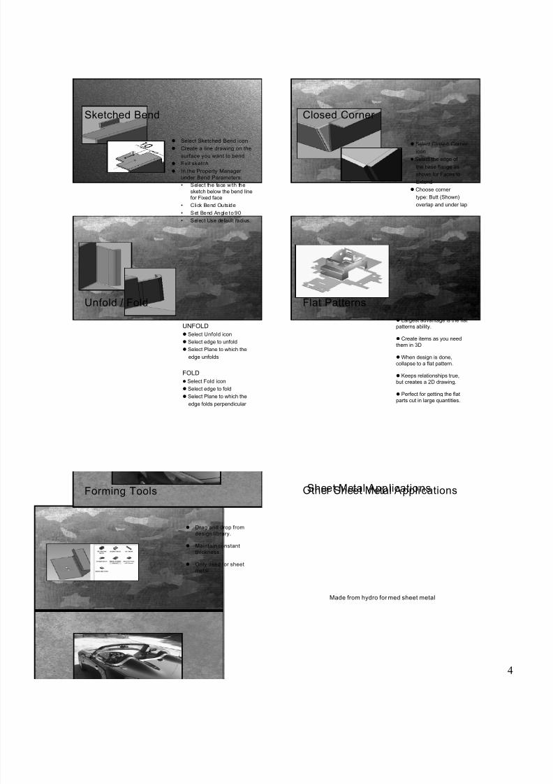
Sketched Bend
z Select Sketched Bend icon
z Create a line drawing on the
surface you want to bend
z Exit sketch
z In the Property Manager
under Bend Parameters:
• Select the face with the
sketch below the bend linefor Fixed face
• Click Bend Outside
• Set Bend Angle to 90
• Select Use default radius.
Closed Corner
z Select Closed Corner
icon
z Select the edge of
the base flange as
shown for Faces to
Extend
z Choose corner
type: Butt (Shown),
overlap and under lap
Unfold / Fold
UNFOLD
z Select Unfold icon
z Select edge to unfold
z Select Plane to which the
edge unfolds
FOLD
z Select Fold icon
z Select edge to fold
z Select Plane to which the
edge folds perpendicular
Flat Patterns
z Largest advantage is the flat
patterns ability.
z Create items as you need
them in 3D
zWhen design is done,
collapse to a flat pattern.
z Keeps relationships true,
but creates a 2D drawing.
z Perfect for getting the flat
parts cut in large quantities.
Forming ToolsForming Tools
z Drag and drop from
design library.
z Maintain constantthickness.
z Only used for sheet
metal
Other Sheet Metal ApplicationsSheet Metal Applications
Made from hydro for med sheet metal

7/27/2019 Sheet Metal HO
http://slidepdf.com/reader/full/sheet-metal-ho 5/5
5
Other sheet Metal Applications
Cont
Custom made Valve Covers
Sheet Metal Applications Other sheet Metal Applications
Cont
Hospital Bench
Sheet Metal Applications
Thank you!
Questions?