Embed Size (px)
Citation preview
© WZL/Fraunhofer IPT
Sheet Metal Forming I
Simulation Techniques in Manufacturing Technology
Lecture 3
Laboratory for Machine Tools and Production Enginee ring
Chair of Manufacturing Technology
Prof. Dr.-Ing. Dr.-Ing. E.h. Dr. h.c. Dr. h.c. F. Klocke
Seite 1© WZL/Fraunhofer IPT
Hydroforming3.6
Spinning Process3.5
Stretch Forming Process3.4
Bending Process3.3
Ironing Process3.2
Deep Drawing Process3.1
Sheet Metal Forming Techniques3
Sheet Material2
Introduction1
Outline
Seite 2© WZL/Fraunhofer IPT
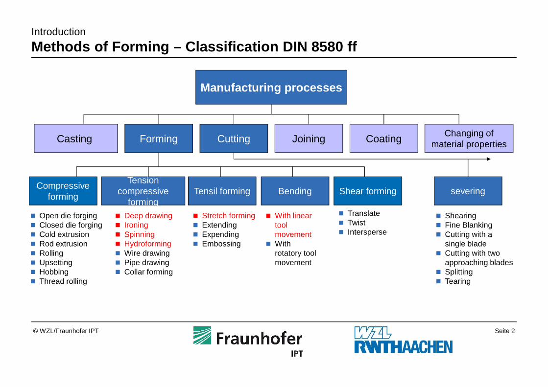
Casting Forming Cutting Joining CoatingChanging of
material properties
Compressive forming
Tension compressive
formingTensil forming Bending Shear forming severing
� Translate� Twist� Intersperse
Manufacturing processes
� Open die forging� Closed die forging� Cold extrusion� Rod extrusion� Rolling� Upsetting� Hobbing� Thread rolling
� Stretch forming� Extending � Expending� Embossing
� Deep drawing� Ironing� Spinning� Hydroforming� Wire drawing� Pipe drawing� Collar forming
� With linear tool movement
� With rotatory tool movement
� Shearing� Fine Blanking� Cutting with a
single blade� Cutting with two
approaching blades� Splitting� Tearing
Introduction
Methods of Forming – Classification DIN 8580 ff
Seite 3© WZL/Fraunhofer IPT
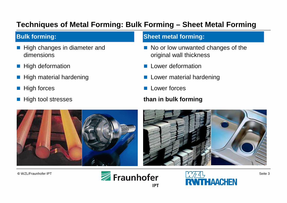
Sheet metal forming:
� No or low unwanted changes of the original wall thickness
� Lower deformation
� Lower material hardening
� Lower forces
than in bulk forming
Techniques of Metal Forming: Bulk Forming – Sheet Me tal Forming
Bulk forming:
� High changes in diameter and dimensions
� High deformation
� High material hardening
� High forces
� High tool stresses
Seite 4© WZL/Fraunhofer IPT
Hydroforming3.6
Spinning Process3.5
Stretch Forming Process3.4
Bending Process3.3
Ironing Process3.2
Deep Drawing Process3.1
Sheet Metal Forming Techniques3
Sheet Material2
Introduction1
Outline
Seite 5© WZL/Fraunhofer IPT
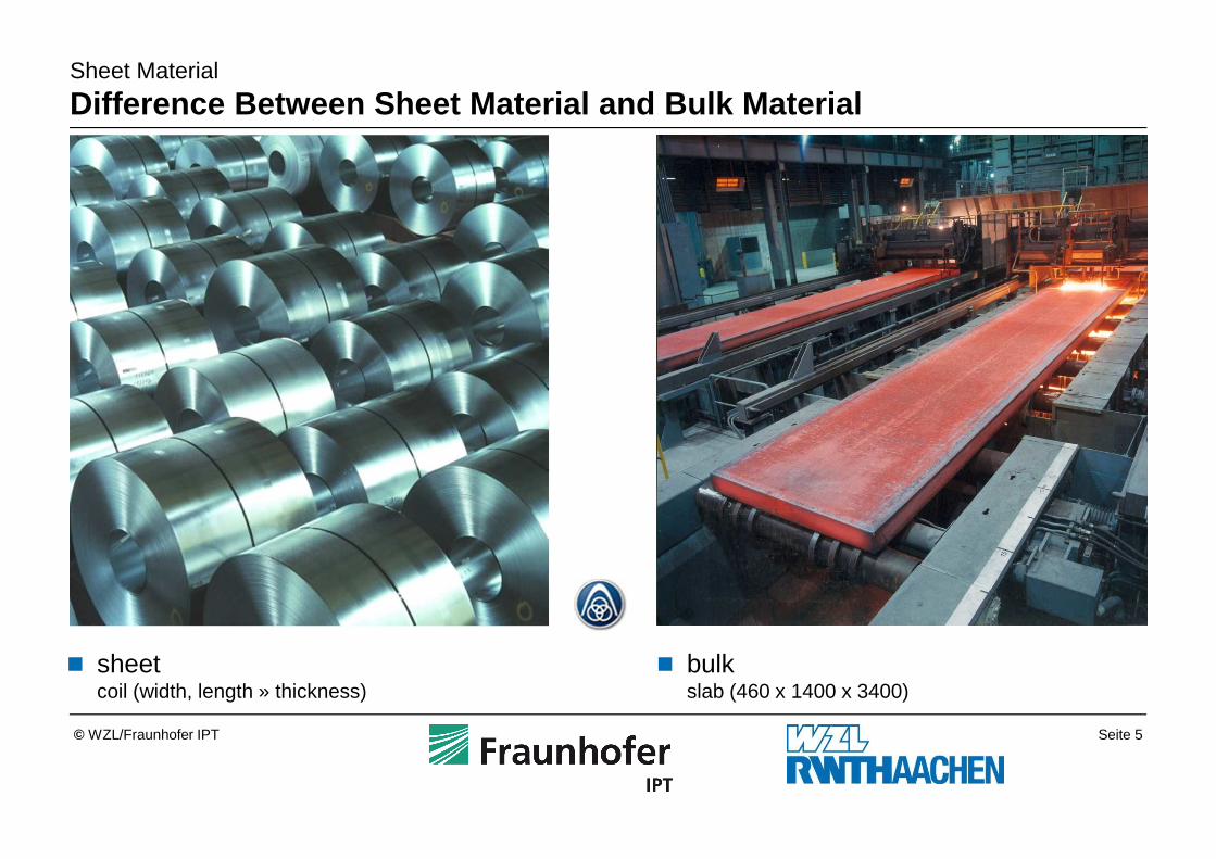
Sheet Material
Difference Between Sheet Material and Bulk Material
� sheetcoil (width, length » thickness)
� bulk slab (460 x 1400 x 3400)
Seite 6© WZL/Fraunhofer IPT
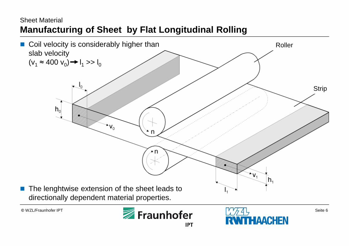
Sheet Material
Manufacturing of Sheet by Flat Longitudinal Rollin g
� Coil velocity is considerably higher than slab velocity(v1 ≈ 400 v0) l1 >> l0
� The lenghtwise extension of the sheet leads to directionally dependent material properties.
Roller
Strip
Seite 7© WZL/Fraunhofer IPT
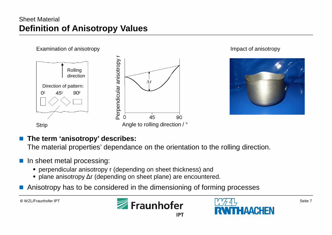
Sheet Material
Definition of Anisotropy Values
� The term ‘anisotropy’ describes:The material properties’ dependance on the orientation to the rolling direction.
� In sheet metal processing:� perpendicular anisotropy r (depending on sheet thickness) and� plane anisotropy ∆r (depending on sheet plane) are encountered.
� Anisotropy has to be considered in the dimensioning of forming processes
Examination of anisotropy Impact of anisotropy
Strip
Rollingdirection
Direction of pattern:
Per
pend
icul
ar a
niso
trop
y r
Angle to rolling direction / °
Seite 8© WZL/Fraunhofer IPT
Sheet Material
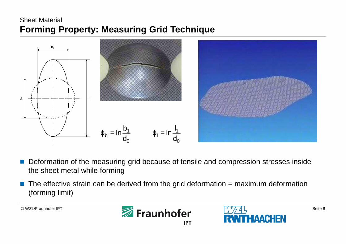
Forming Property: Measuring Grid Technique
� Deformation of the measuring grid because of tensile and compression stresses inside the sheet metal while forming
� The effective strain can be derived from the grid deformation = maximum deformation (forming limit)
0
1b d
bln=ϕ
0
1l d
lln=ϕ
Seite 9© WZL/Fraunhofer IPT
Sheet Material
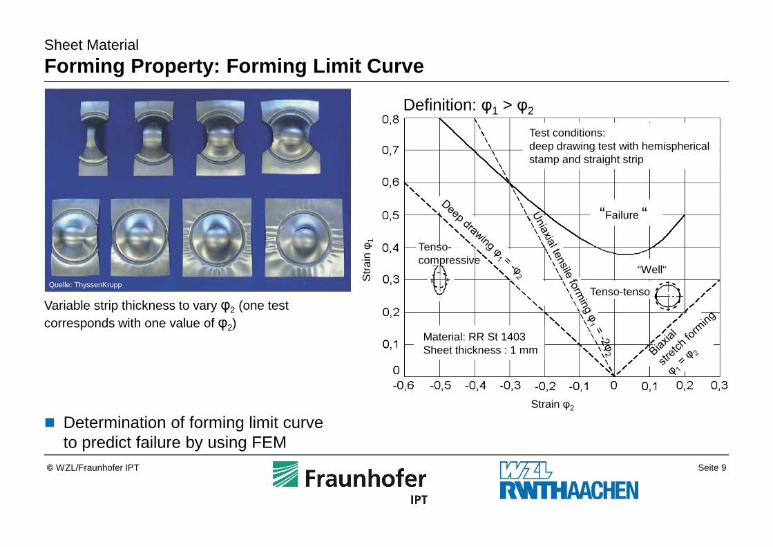
Forming Property: Forming Limit Curve
� Determination of forming limit curveto predict failure by using FEM
Quelle: ThyssenKrupp
Variable strip thickness to vary φ2 (one test corresponds with one value of φ2)
Definition: φ1 > φ2
Strain φ2
Str
ain φ
1
Material: RR St 1403Sheet thickness : 1 mm
“Well“
“Failure “
Test conditions:deep drawing test with hemispherical stamp and straight strip
Tenso-tenso
Tenso-compressive
Seite 10© WZL/Fraunhofer IPT
Sheet Material
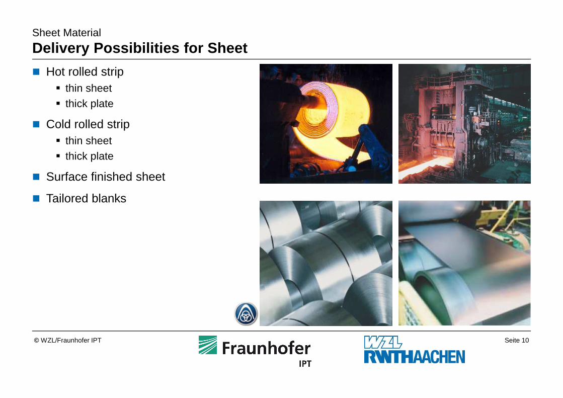
Delivery Possibilities for Sheet
� Hot rolled strip� thin sheet� thick plate
� Cold rolled strip� thin sheet� thick plate
� Surface finished sheet
� Tailored blanks
Seite 11© WZL/Fraunhofer IPT
Sheet Material
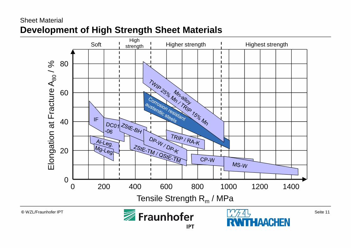
Development of High Strength Sheet MaterialsHigh
strength
0
20
40
60
80
Elo
ngat
ion
at F
ract
ure
A80
/ %
Tensile Strength Rm / MPa0 200 400 600 800 1000 1200 1400
IF
Soft Higher strength Highest strength
Seite 12© WZL/Fraunhofer IPT
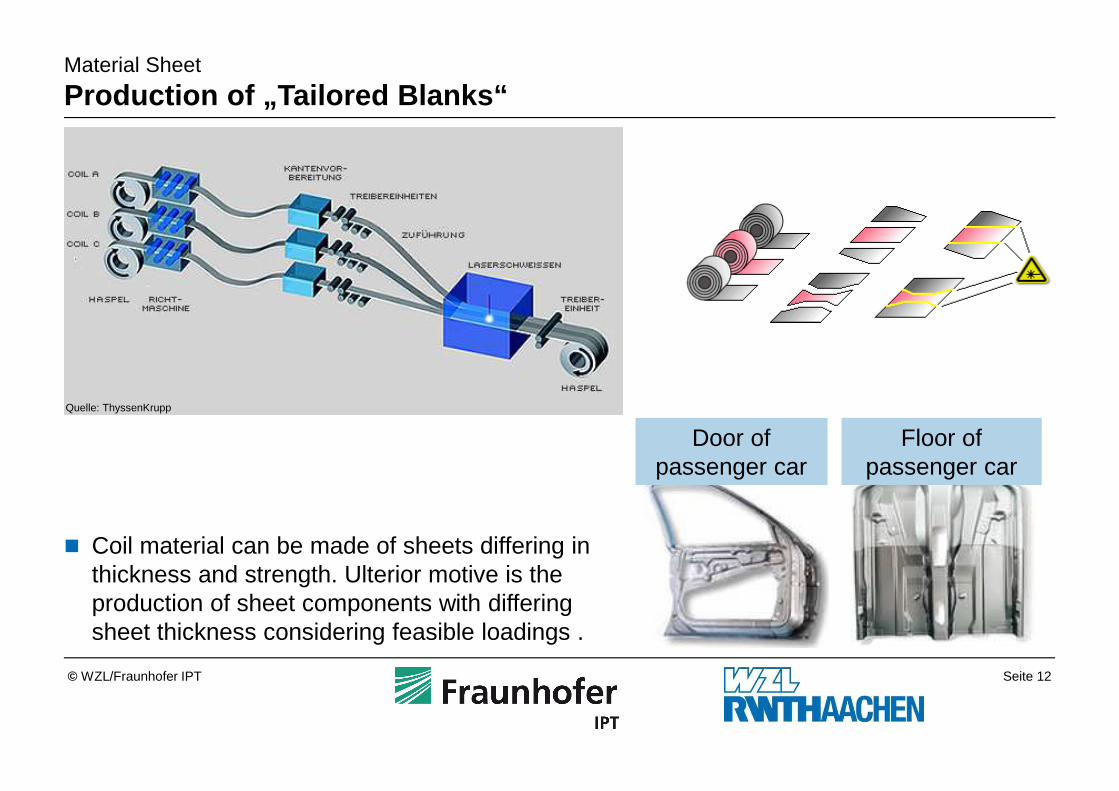
Material Sheet
Production of „Tailored Blanks“
Quelle: ThyssenKrupp
� Coil material can be made of sheets differing in thickness and strength. Ulterior motive is the production of sheet components with differing sheet thickness considering feasible loadings .
Floor of passenger car
Door ofpassenger car
Seite 13© WZL/Fraunhofer IPT
Hydroforming3.6
Spinning Process3.5
Stretch Forming Process3.4
Bending Process3.3
Ironing Process3.2
Deep Drawing Process3.1
Sheet Metal Forming Techniques3
Sheet Material2
Introduction1
Outline
Seite 14© WZL/Fraunhofer IPT
Hydroforming3.6
Spinning Process3.5
Stretch Forming Process3.4
Bending Process3.3
Ironing Process3.2
Deep Drawing Process3.1
Sheet Metal Forming Techniques3
Sheet Material2
Introduction1
Outline
Seite 15© WZL/Fraunhofer IPT
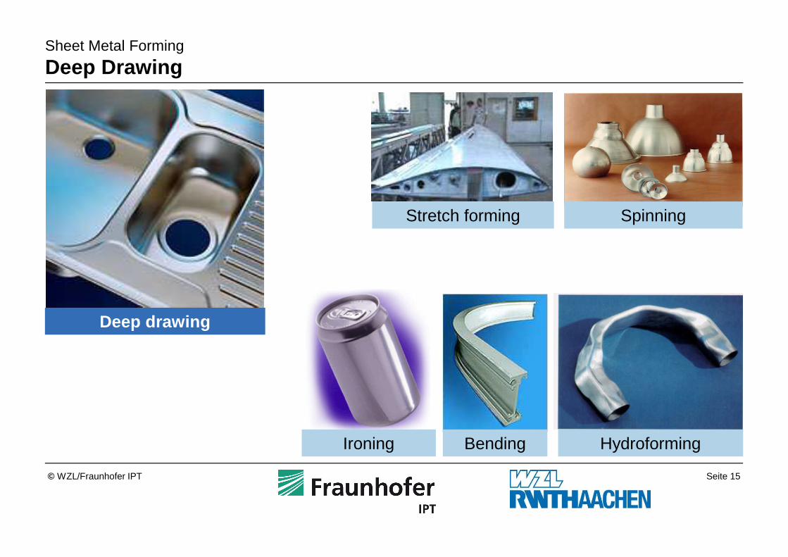
Sheet Metal Forming
Deep Drawing
Ironing Bending
Stretch forming Spinning
Hydroforming
Deep drawing
Seite 16© WZL/Fraunhofer IPT
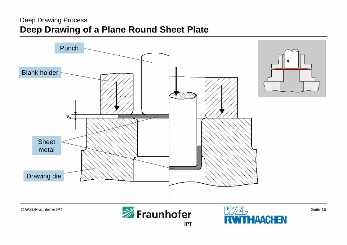
Deep Drawing Process
Deep Drawing of a Plane Round Sheet Plate
Punch
Blank holder
Sheet metal
Drawing die
Seite 17© WZL/Fraunhofer IPT
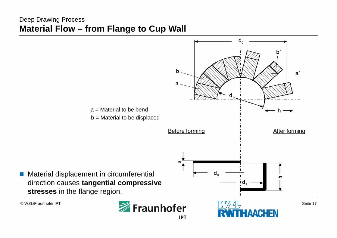
Deep Drawing Process
Material Flow – from Flange to Cup Wall
� Material displacement in circumferential direction causes tangential compressive stresses in the flange region.
a = Material to be bendb = Material to be displaced
Before forming After forming
Seite 18© WZL/Fraunhofer IPT
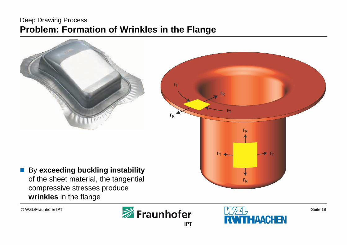
Deep Drawing Process
Problem: Formation of Wrinkles in the Flange
� By exceeding buckling instabilityof the sheet material, the tangential compressive stresses produce wrinkles in the flange
Seite 19© WZL/Fraunhofer IPT
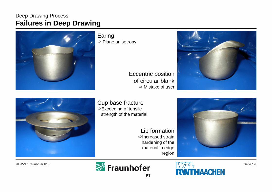
Deep Drawing Process
Failures in Deep Drawing
Earing� Plane anisotropy
Eccentric position of circular blank
� Mistake of user
Cup base fracture�Exceeding of tensile
strength of the material
Lip formation�Increased strain
hardening of the material in edge
region
Seite 20© WZL/Fraunhofer IPT
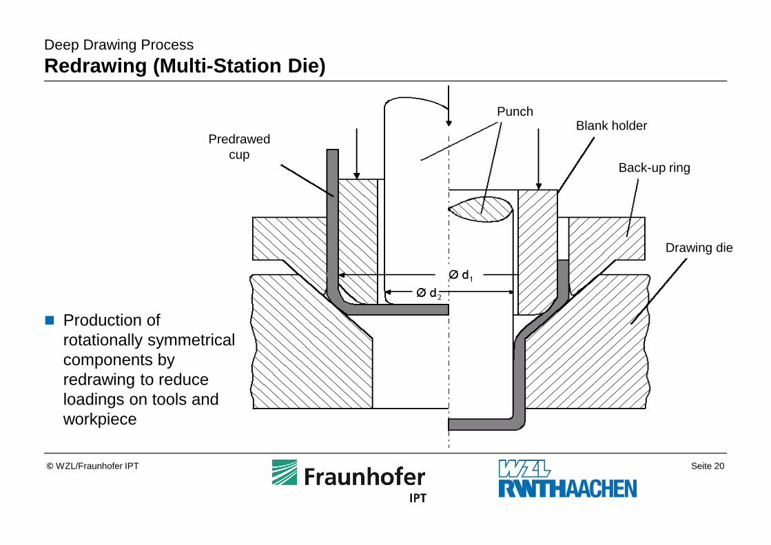
Deep Drawing Process
Redrawing (Multi-Station Die)
� Production of rotationally symmetrical components by redrawing to reduce loadings on tools and workpiece
PunchBlank holder
Drawing die
Predrawedcup
Back-up ring
Seite 21© WZL/Fraunhofer IPT
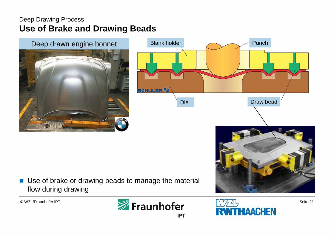
Deep Drawing Process
Use of Brake and Drawing Beads
� Use of brake or drawing beads to manage the material flow during drawing
Blank holder Punch
Die Draw bead
Deep drawn engine bonnet
Seite 22© WZL/Fraunhofer IPT
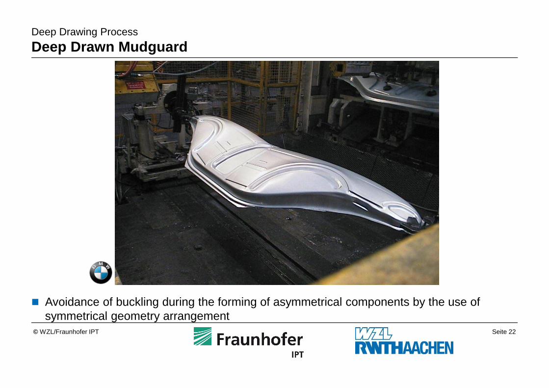
Deep Drawing Process
Deep Drawn Mudguard
� Avoidance of buckling during the forming of asymmetrical components by the use of symmetrical geometry arrangement
Seite 23© WZL/Fraunhofer IPT
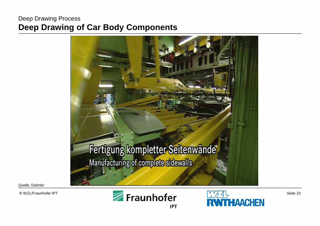
Deep Drawing Process
Deep Drawing of Car Body Components
Quelle: Daimler
Seite 24© WZL/Fraunhofer IPT
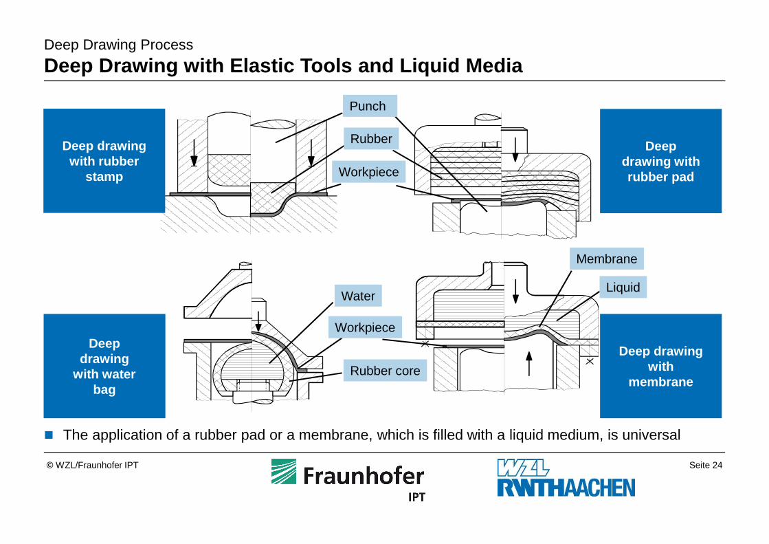
Deep Drawing Process
Deep Drawing with Elastic Tools and Liquid Media
Deep drawing with rubber
stamp
Deep drawing with rubber pad
Deep drawing
with water bag
Deep drawingwith
membrane
Membrane
LiquidWater
Workpiece
Rubber core
Punch
Rubber
Workpiece
� The application of a rubber pad or a membrane, which is filled with a liquid medium, is universal
Seite 25© WZL/Fraunhofer IPT
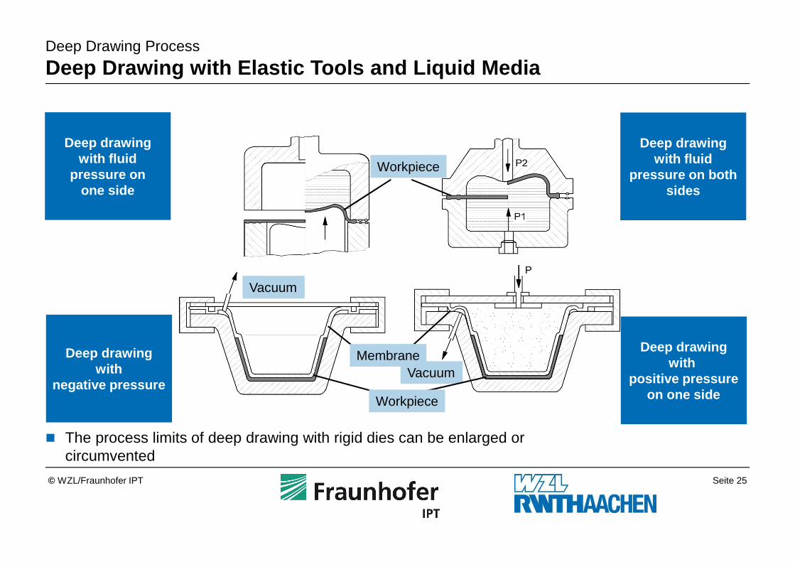
Deep Drawing Process
Deep Drawing with Elastic Tools and Liquid Media
Deep drawing with fluid
pressure on one side
Deep drawing with fluid
pressure on both sides
Deep drawingwith
negative pressure
Deep drawingwith
positive pressureon one side
Workpiece
Vacuum
Vacuum
� The process limits of deep drawing with rigid dies can be enlarged or circumvented
Workpiece
Membrane
Seite 26© WZL/Fraunhofer IPT
Hydroforming3.6
Spinning Process3.5
Stretch Forming Process3.4
Bending Process3.3
Ironing Process3.2
Deep Drawing Process3.1
Sheet Metal Forming Techniques3
Sheet Material2
Introduction1
Outline
Seite 27© WZL/Fraunhofer IPT
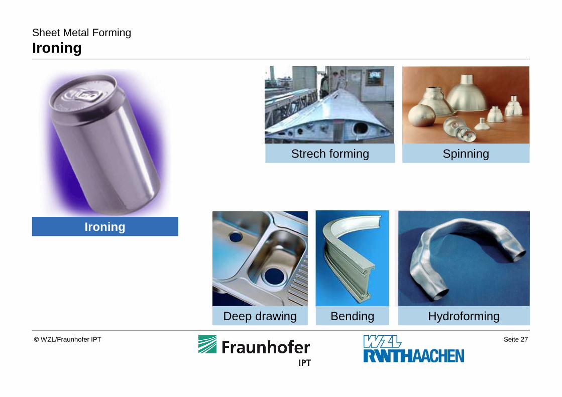
Sheet Metal Forming
Ironing
Ironing
Strech forming Spinning
BendingDeep drawing Hydroforming
Seite 28© WZL/Fraunhofer IPT
Ironing Process
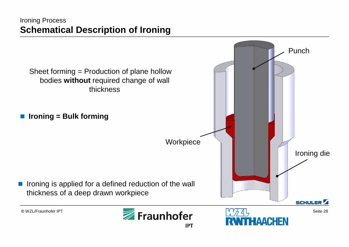
Schematical Description of Ironing
Sheet forming = Production of plane hollow bodies without required change of wall
thickness
� Ironing = Bulk forming
� Ironing is applied for a defined reduction of the wall thickness of a deep drawn workpiece
Punch
Ironing die
Workpiece
Seite 29© WZL/Fraunhofer IPT
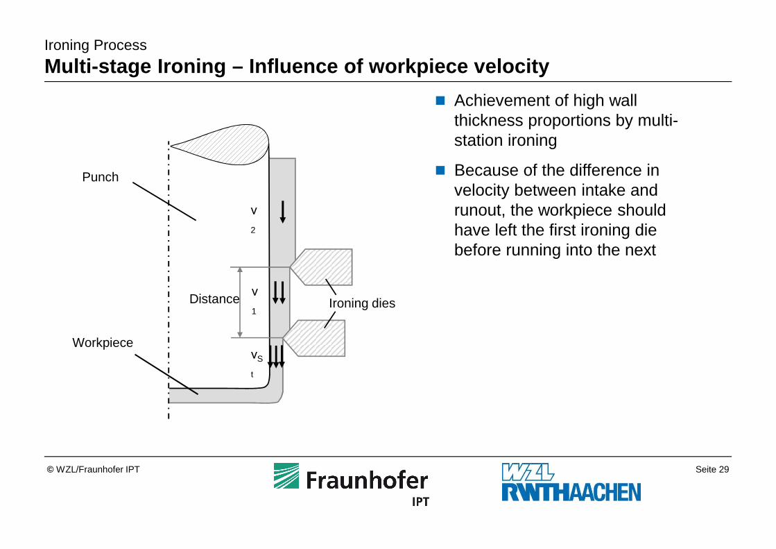
� Achievement of high wall thickness proportions by multi-station ironing
� Because of the difference in velocity between intake and runout, the workpiece should have left the first ironing die before running into the next
Ironing Process
Multi-stage Ironing – Influence of workpiece velocity
Ironing diesν
1
ν
2
νS
t
Distance
Punch
Workpiece
Seite 30© WZL/Fraunhofer IPT
Ironing Process
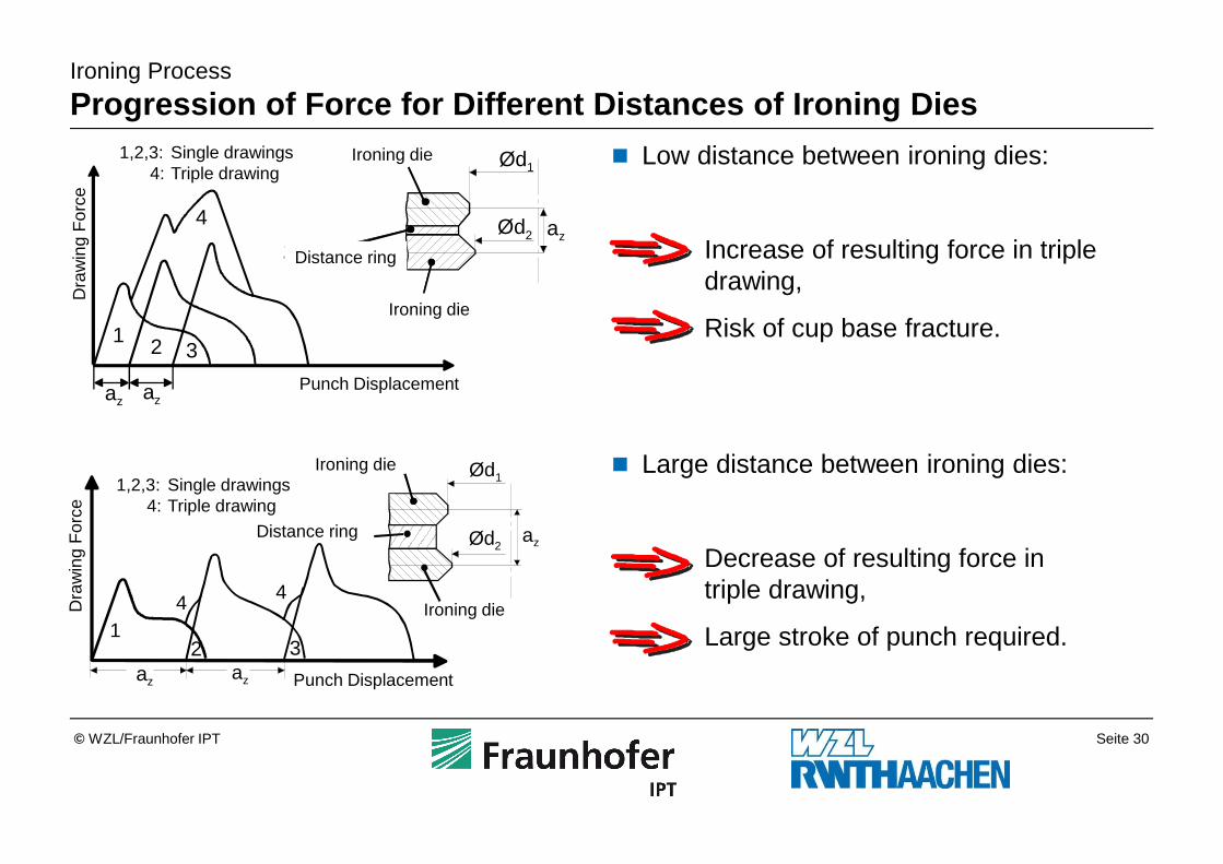
Progression of Force for Different Distances of Iro ning Dies
� Low distance between ironing dies:
Increase of resulting force in triple drawing,
Risk of cup base fracture.
� Large distance between ironing dies:
Decrease of resulting force in triple drawing,
Large stroke of punch required.12 3
44
az az
Ød1
azØd2
Dra
win
g F
orce
Punch Displacement
Ironing die
Ironing die
Distance ring
1,2,3: Single drawings4: Triple drawing
1 2 3
az az
4 azØd2
Ød1
Dra
win
g F
orce
Punch Displacement
Ironing die
Zwischenring
Abstreckring
1,2,3: Single drawings4: Triple drawing
Distance ring
Ironing die
Seite 31© WZL/Fraunhofer IPT
Ironing Process
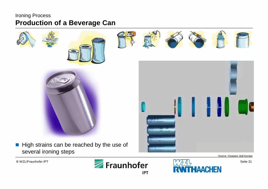
Production of a Beverage Can
Source: Visypack, Ball Europe
� High strains can be reached by the use of several ironing steps
Seite 32© WZL/Fraunhofer IPT
Hydroforming3.6
Spinning Process3.5
Stretch Forming Process3.4
Bending Process3.3
Ironing Process3.2
Deep Drawing Process3.1
Sheet Metal Forming Techniques3
Sheet Material2
Introduction1
Outline
Seite 33© WZL/Fraunhofer IPT
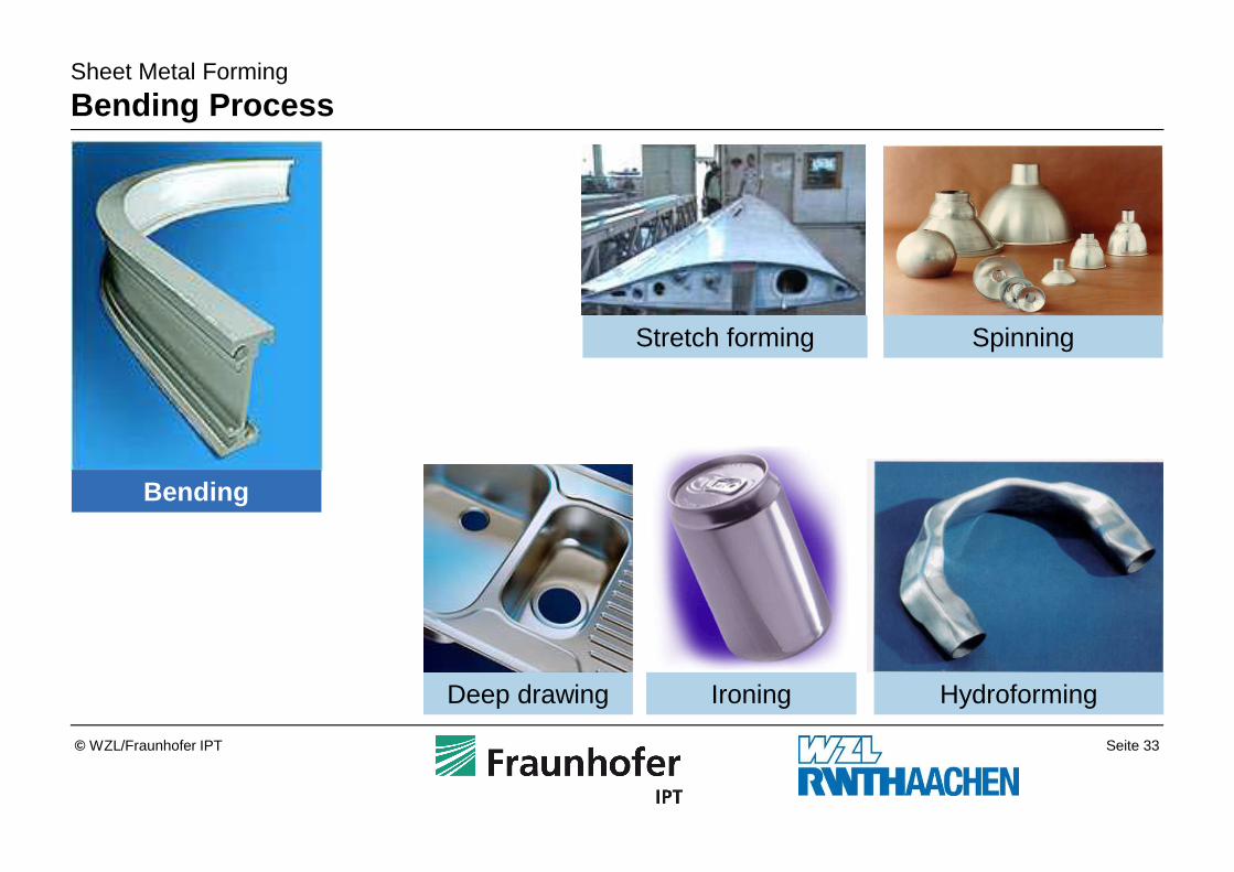
Sheet Metal Forming
Bending Process
Bending
Deep drawing Ironing
Stretch forming Spinning
Hydroforming
Seite 34© WZL/Fraunhofer IPT
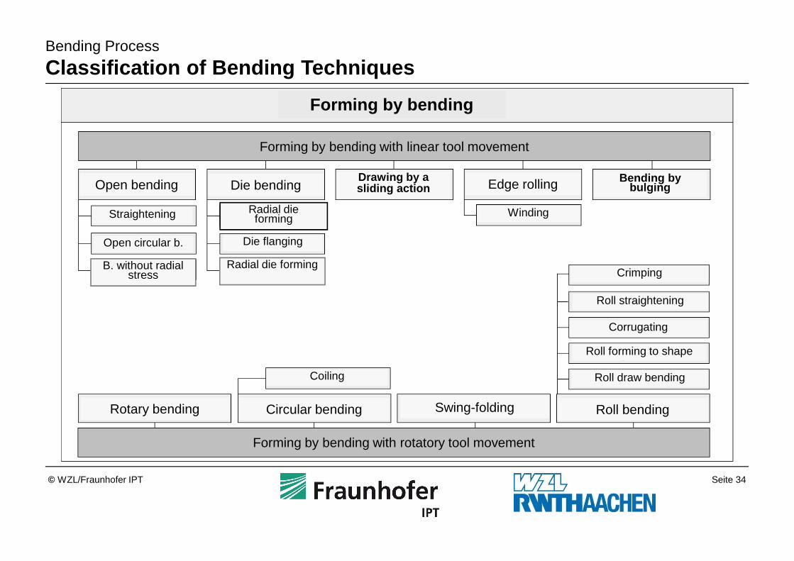
Bending Process
Classification of Bending Techniques
Forming by bending
Forming by bending with linear tool movement
Open bending
Straightening
Open circular b.
B. without radial stress
Drawing by a sliding action Edge rolling
Winding
Bending by bulging
Forming by bending with rotatory tool movement
Rotary bending Circular bending
Coiling
Swing-folding Roll bending
Crimping
Roll straightening
Roll forming to shape
Roll draw bending
Die bending
Radial die forming
Radial die forming
Die flanging
Corrugating
Seite 35© WZL/Fraunhofer IPT
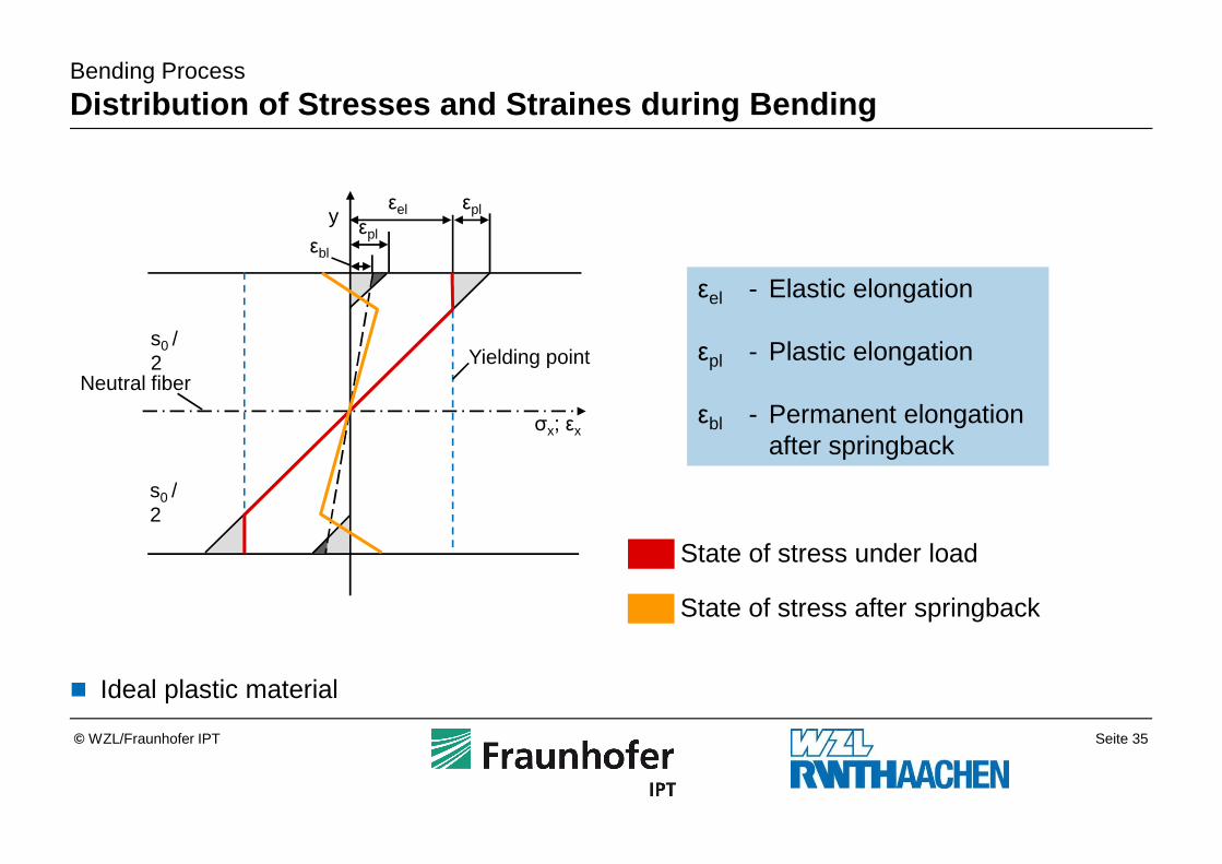
Bending Process
Distribution of Stresses and Straines during Bendin g
� Ideal plastic material
y
σx; εx
s0 / 2
s0 / 2
Neutral fiberYielding point
εplεel
εplεbl
εel - Elastic elongation
εpl - Plastic elongation
εbl - Permanent elongation after springback
State of stress under load
State of stress after springback
Seite 36© WZL/Fraunhofer IPT
Bending Process
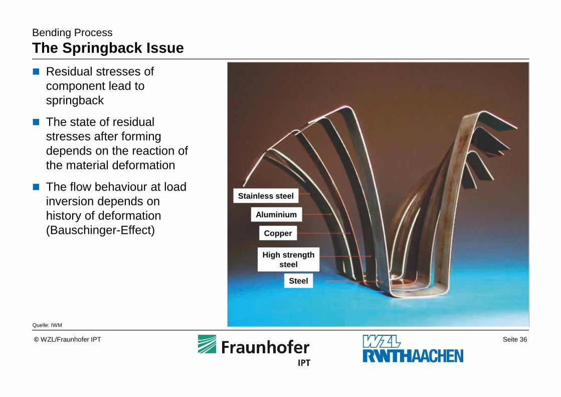
The Springback Issue
Quelle: IWM
� Residual stresses of component lead to springback
� The state of residual stresses after forming depends on the reaction of the material deformation
� The flow behaviour at load inversion depends on history of deformation (Bauschinger-Effect)
Stainless steel
Aluminium
Copper
High strengthsteel
Steel
Seite 37© WZL/Fraunhofer IPT
Bending Process
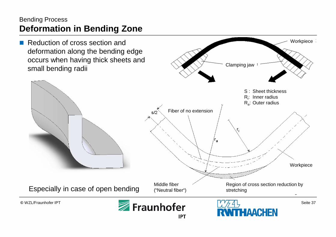
Deformation in Bending Zone
� Reduction of cross section and deformation along the bending edge occurs when having thick sheets and small bending radii
Especially in case of open bending
Workpiece
Workpiece
Clamping jaw
S : Sheet thicknessRi: Inner radiusRa: Outer radius
Middle fiber(“Neutral fiber“)
Fiber of no extension
Region of cross section reduction by stretching
Seite 38© WZL/Fraunhofer IPT
Bending Process
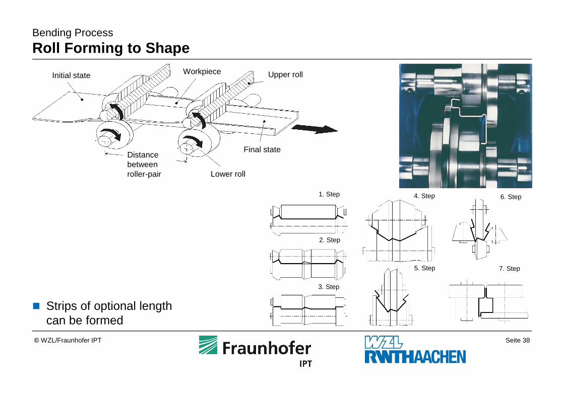
Roll Forming to Shape
� Strips of optional length can be formed
Workpiece
Distance between roller-pair
Initial state
Final state
Upper roll
Lower roll
1. Step
2. Step
3. Step
4. Step
5. Step
6. Step
7. Step
Seite 39© WZL/Fraunhofer IPT
Bending Process
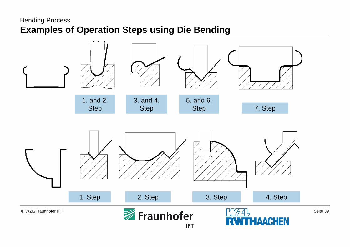
Examples of Operation Steps using Die Bending
1. and 2.Step
3. and 4.Step
5. and 6.Step 7. Step
1. Step 2. Step 3. Step 4. Step
Seite 40© WZL/Fraunhofer IPT
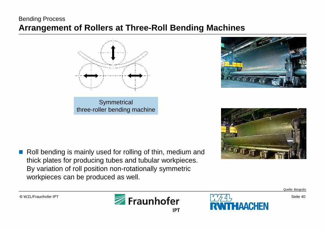
Symmetricalthree-roller bending machine
� Roll bending is mainly used for rolling of thin, medium and thick plates for producing tubes and tubular workpieces. By variation of roll position non-rotationally symmetric workpieces can be produced as well.
Quelle: Bergrohr
Bending Process
Arrangement of Rollers at Three-Roll Bending Machin es
Seite 41© WZL/Fraunhofer IPT
Hydroforming3.6
Spinning Process3.5
Stretch Forming Process3.4
Bending Process3.3
Ironing Process3.2
Deep Drawing Process3.1
Sheet Metal Forming Techniques3
Sheet Material2
Introduction1
Outline
Seite 42© WZL/Fraunhofer IPT
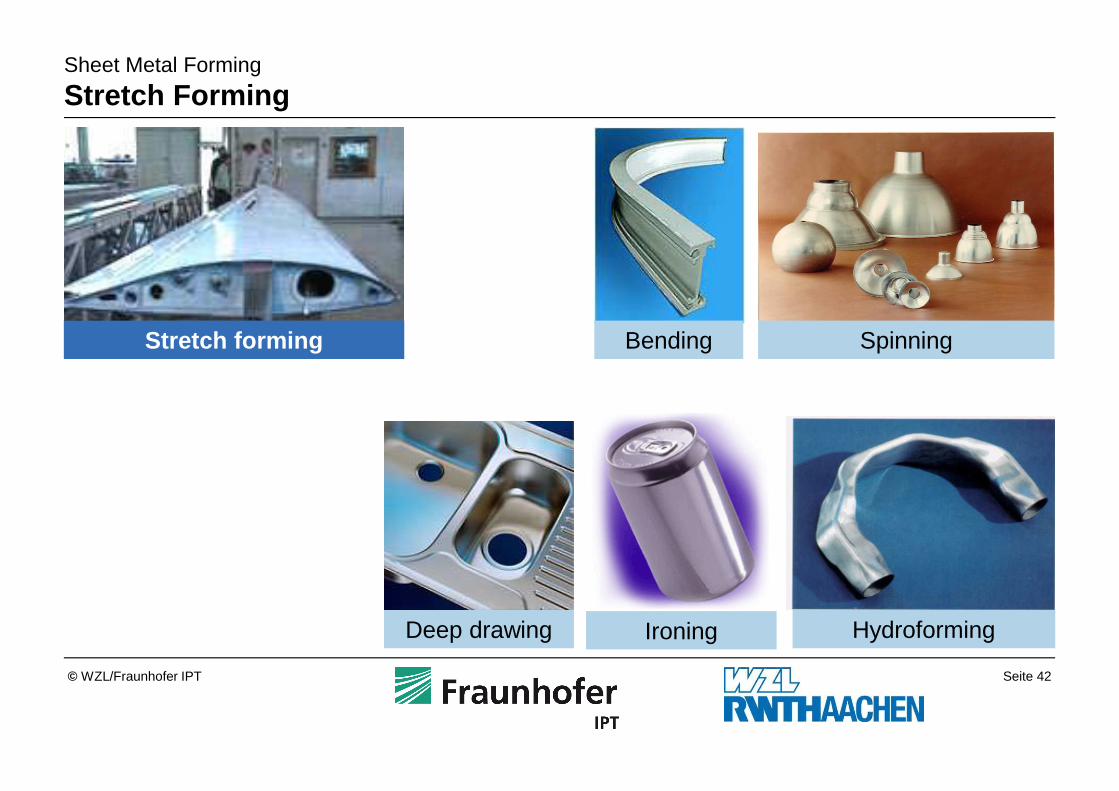
Sheet Metal Forming
Stretch Forming
Stretch forming SpinningBending
Deep drawing Ironing Hydroforming
Seite 43© WZL/Fraunhofer IPT
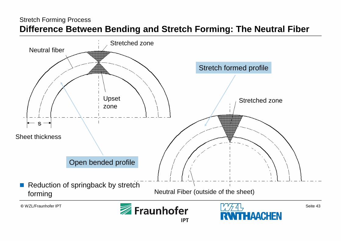
Stretch Forming Process
Difference Between Bending and Stretch Forming: The Neutral Fiber
Open bended profile
Stretch formed profile
� Reduction of springback by stretch forming
Neutral fiberStretched zone
Upset zone
Sheet thickness
Stretched zone
Neutral Fiber (outside of the sheet)
Seite 44© WZL/Fraunhofer IPT
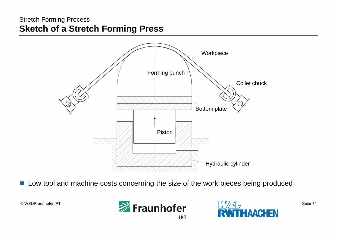
Stretch Forming Process
Sketch of a Stretch Forming Press
� Low tool and machine costs concerning the size of the work pieces being produced
Workpiece
Collet chuck
Forming punch
Bottom plate
Piston
Hydraulic cylinder
Seite 45© WZL/Fraunhofer IPT
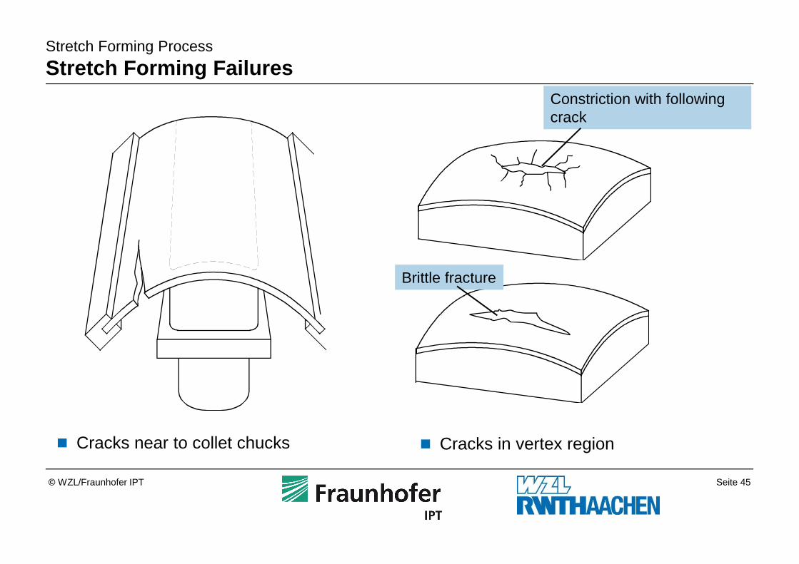
Stretch Forming Process
Stretch Forming Failures
� Cracks near to collet chucks � Cracks in vertex region
Brittle fracture
Constriction with following crack
Seite 46© WZL/Fraunhofer IPT
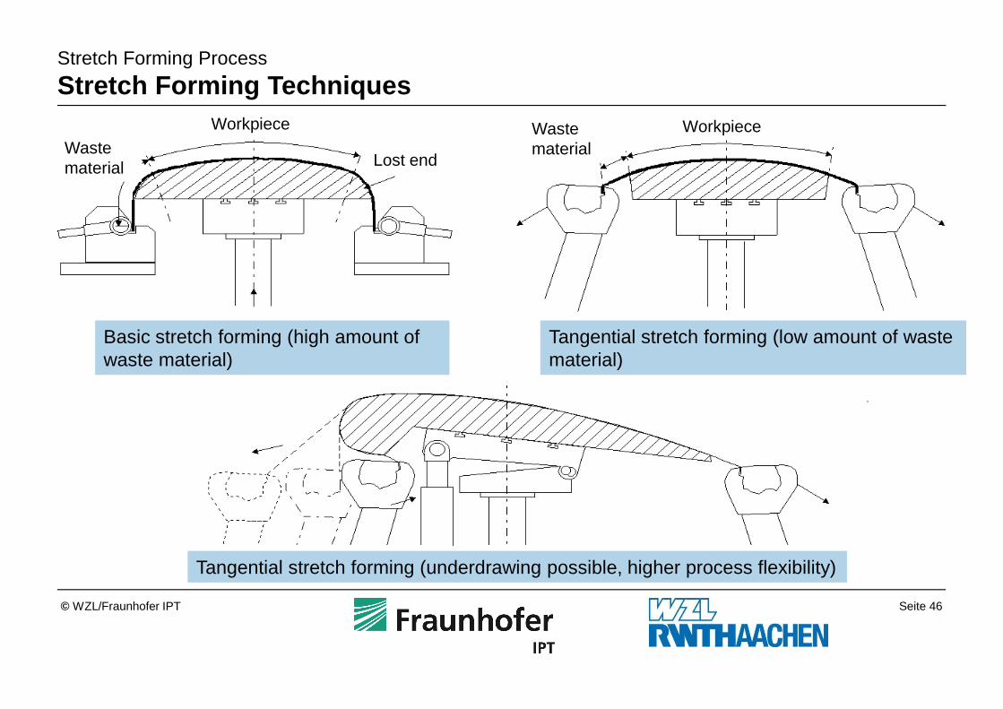
Stretch Forming Process
Stretch Forming Techniques
Basic stretch forming (high amount of waste material)
Tangential stretch forming (low amount of waste material)
Tangential stretch forming (underdrawing possible, higher process flexibility)
Workpiece WorkpieceWaste material Lost end
Waste material
Seite 47© WZL/Fraunhofer IPT
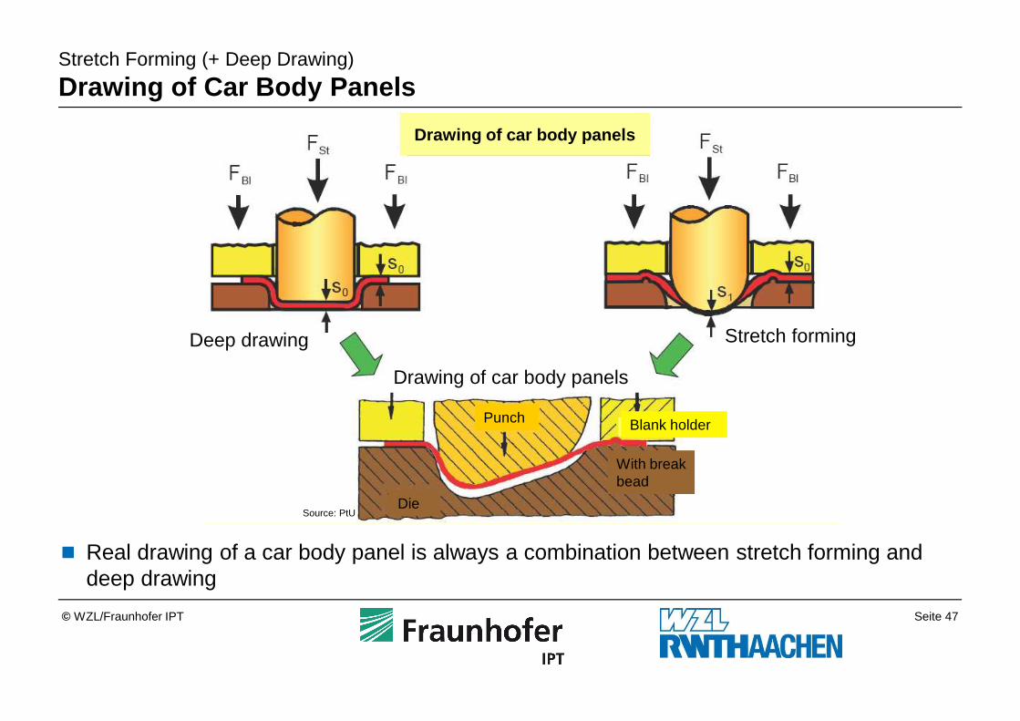
Stretch Forming (+ Deep Drawing)
Drawing of Car Body Panels
Source: PtU
� Real drawing of a car body panel is always a combination between stretch forming and deep drawing
Deep drawing Stretch forming
Die
Punch
Drawing of car body panels
Drawing of car body panels
Blank holder
With breakbead
Seite 48© WZL/Fraunhofer IPT
Hydroforming3.6
Spinning Process3.5
Stretch Forming Process3.4
Bending Process3.3
Ironing Process3.2
Deep Drawing Process3.1
Sheet Metal Forming Techniques3
Sheet Material2
Introduction1
Outline
Seite 49© WZL/Fraunhofer IPT
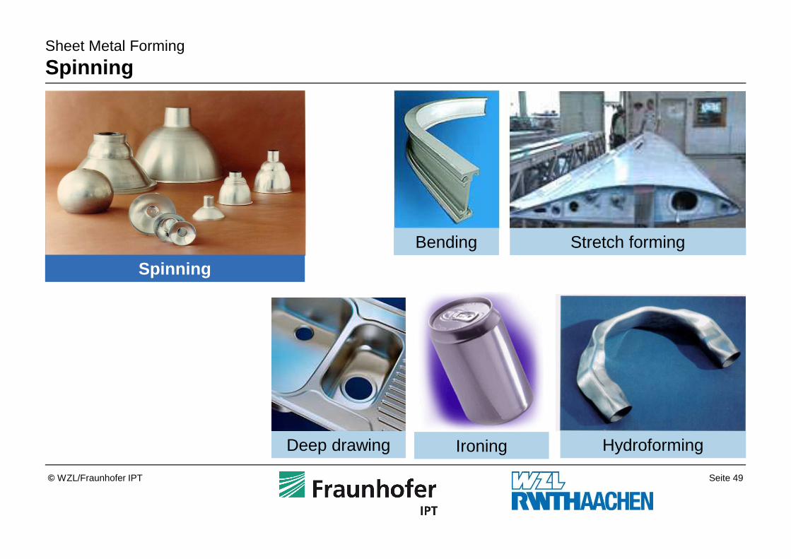
Sheet Metal Forming
Spinning
Spinning
Bending Stretch forming
Deep drawing Ironing Hydroforming
Seite 50© WZL/Fraunhofer IPT
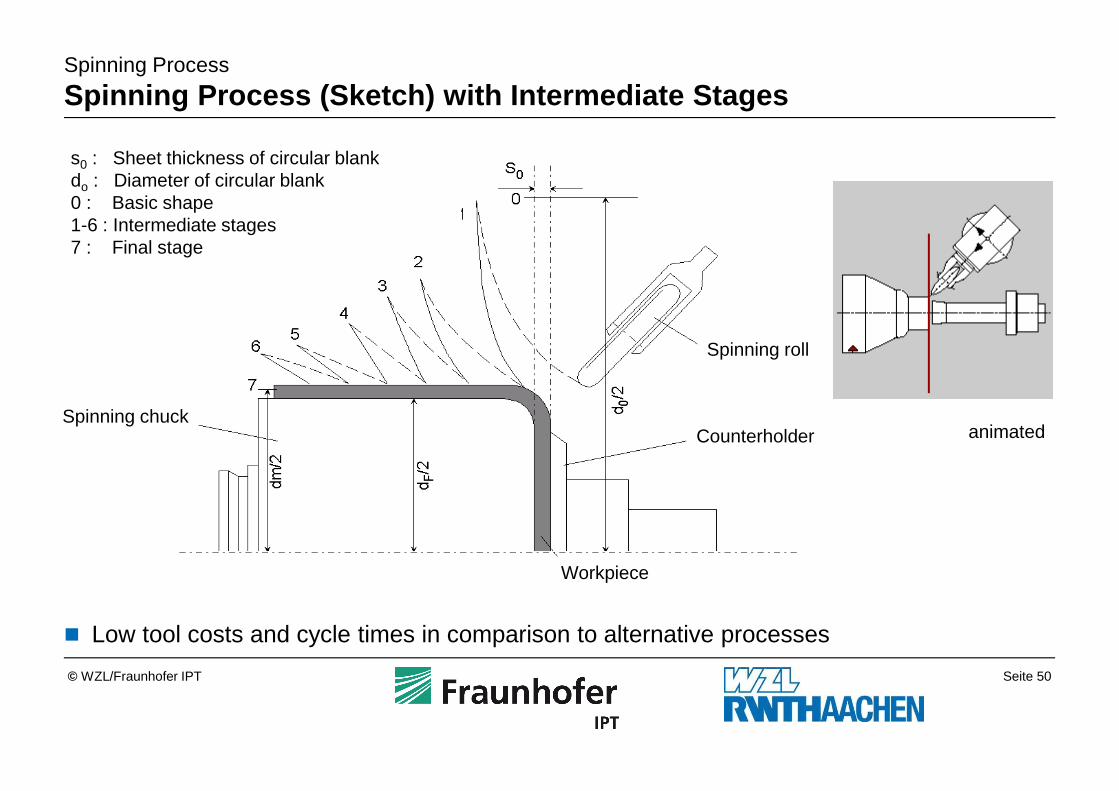
Spinning Process
Spinning Process (Sketch) with Intermediate Stages
Projizierstreckdrücken
� Low tool costs and cycle times in comparison to alternative processes
animiert
s0 : Sheet thickness of circular blankdo : Diameter of circular blank0 : Basic shape1-6 : Intermediate stages7 : Final stage
Spinning chuck
Spinning roll
Workpiece
Counterholder animated
Seite 51© WZL/Fraunhofer IPT
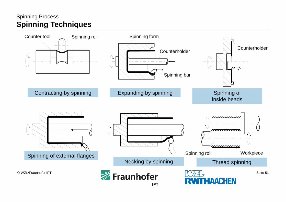
Spinning Process
Spinning Techniques
DrückwalzeGegenwerkzeug
Engen durch Drücken
Drückform
Gegenhalter
Drückstab
Aufweiten durch Drücken
Gegenhalter
Erzeugen von Innenbordendurch Drücken
Erzeugen von Außenbordendurch Drücken
WerkstückDrückwalze
Einhalsen durch Drücken Gewindedrücken
Contracting by spinning Expanding by spinning Spinning of inside beads
Spinning of external flangesThread spinning
Counter tool Spinning roll Spinning form
CounterholderCounterholder
Spinning roll Workpiece
Spinning bar
Necking by spinning
Seite 52© WZL/Fraunhofer IPT
Spinning Process
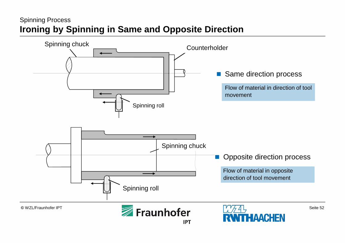
Ironing by Spinning in Same and Opposite Direction
� Same direction process
Flow of material in direction of tool movement
� Opposite direction process
Flow of material in opposite direction of tool movement
Drückfutter
Drückrolle
Gegenhalter
Drückfutter
Drückrolle
Spinning chuck Counterholder
Spinning roll
Spinning chuck
Spinning roll
Seite 53© WZL/Fraunhofer IPT
Spinning Process
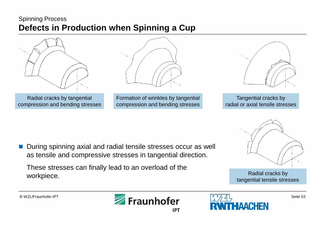
Defects in Production when Spinning a Cup
Formation of wrinkles by tangentialcompression and bending stresses
Tangential cracks byradial or axial tensile stresses
Radial cracks bytangential tensile stresses
� During spinning axial and radial tensile stresses occur as well as tensile and compressive stresses in tangential direction.
These stresses can finally lead to an overload of the workpiece.
Radial cracks by tangentialcompression and bending stresses
Seite 54© WZL/Fraunhofer IPT
Spinning Process
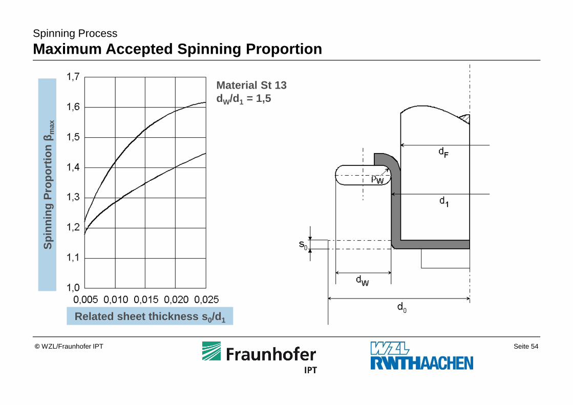
Maximum Accepted Spinning Proportion
Related sheet thickness s 0/d1
Spi
nnin
g P
ropo
rtio
n β
max
Material St 13dW/d1 = 1,5
Seite 55© WZL/Fraunhofer IPT
Spinning Process
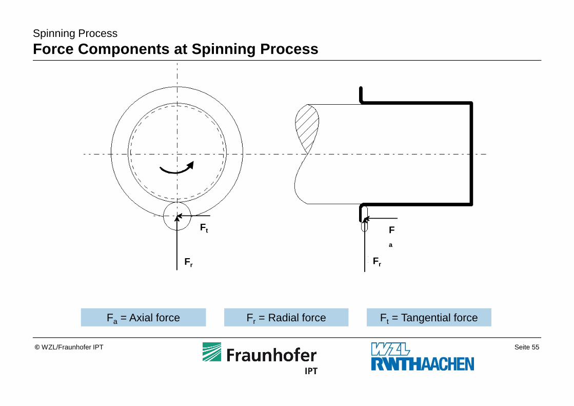
Force Components at Spinning Process
Fa = Axial force Fr = Radial force Ft = Tangential force
Fa
FrFr
Ft
Seite 56© WZL/Fraunhofer IPT
Spinning Process
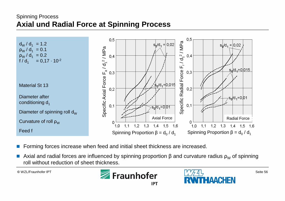
Axial und Radial Force at Spinning Process
Material St 13
Diameter after conditioning d1
Diameter of spinning roll dW
Curvature of roll ρW
Feed f
dW / d1 = 1.2ρW / d1 = 0.1ρW / d1 = 0.2f / d1 = 0,17 · 10-2
� Forming forces increase when feed and initial sheet thickness are increased.
� Axial and radial forces are influenced by spinning proportion β and curvature radius ρW of spinning roll without reduction of sheet thickness.
Spinning Proportion β = d0 / d1 Spinning Proportion β = d0 / d1
Spe
cific
Axi
al F
orce
Fa
/ d12
/ MP
a
Spe
cific
Rad
ial F
orce
Fr/ d
12/ M
Pa
Axial Force Radial Force
Seite 57© WZL/Fraunhofer IPT
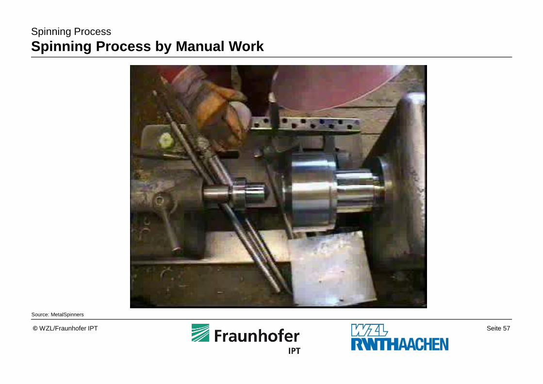
Spinning Process
Spinning Process by Manual Work
Source: MetalSpinners
Seite 58© WZL/Fraunhofer IPT
Spinning Process
Roll Spinning Pulley
Source: Leico
Seite 59© WZL/Fraunhofer IPT
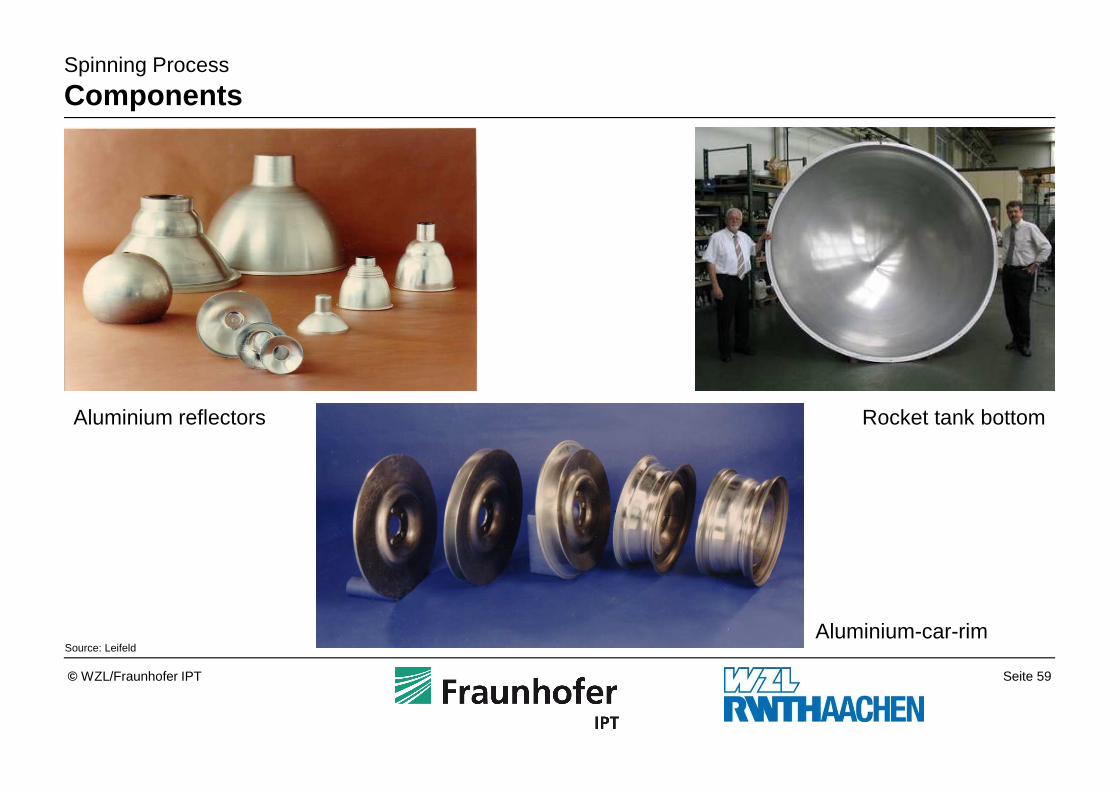
Aluminium reflectors
Spinning Process
Components
Rocket tank bottom
Aluminium-car-rimSource: Leifeld
Seite 60© WZL/Fraunhofer IPT
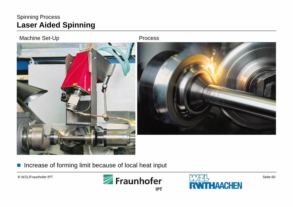
Spinning Process
Laser Aided Spinning
Machine Set-Up Process
� Increase of forming limit because of local heat input
Seite 61© WZL/Fraunhofer IPT
Hydroforming3.6
Spinning Process3.5
Stretch Forming Process3.4
Bending Process3.3
Ironing Process3.2
Deep Drawing Process3.1
Sheet Metal Forming Techniques3
Sheet Material2
Introduction1
Outline
Seite 62© WZL/Fraunhofer IPT
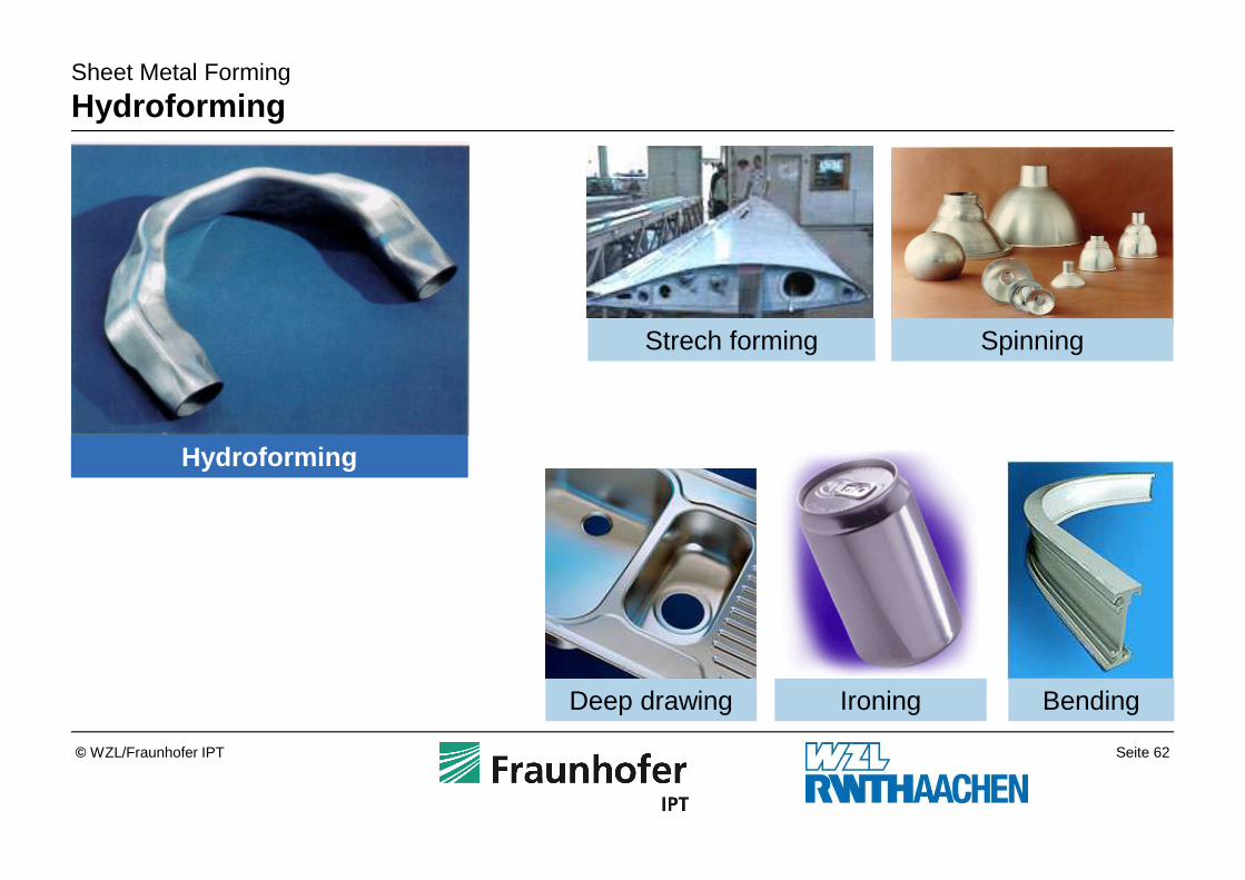
Sheet Metal Forming
Hydroforming
Hydroforming
Deep drawing Ironing Bending
Strech forming Spinning
Seite 63© WZL/Fraunhofer IPT
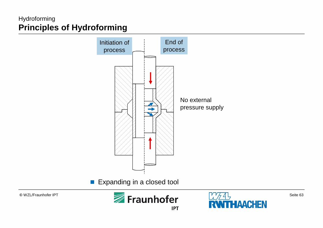
Hydroforming
Principles of Hydroforming
� Expanding in a closed tool
Prozess-ende
Prozess-beginn
keine externeDruckversorgung
Initiation ofprocess
End ofprocess
No external pressure supply
Seite 64© WZL/Fraunhofer IPT
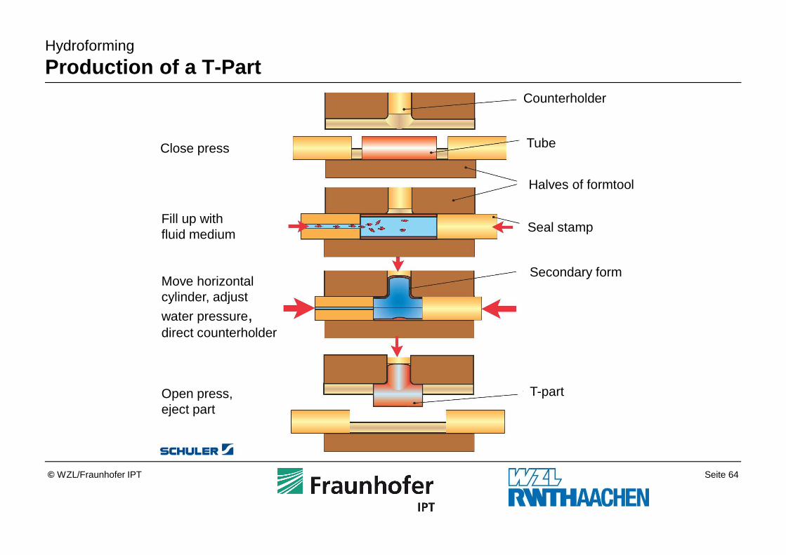
Hydroforming
Production of a T-Part
Close press
Fill up withfluid medium
Move horizontal cylinder, adjust
water pressure, direct counterholder
Open press, eject part
Counterholder
Tube
Halves of formtool
Seal stamp
Secondary form
T-part
Seite 65© WZL/Fraunhofer IPT
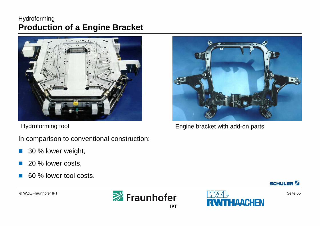
Hydroforming tool Engine bracket with add-on parts
Hydroforming
Production of a Engine Bracket
In comparison to conventional construction:
� 30 % lower weight,
� 20 % lower costs,
� 60 % lower tool costs.
Seite 66© WZL/Fraunhofer IPT
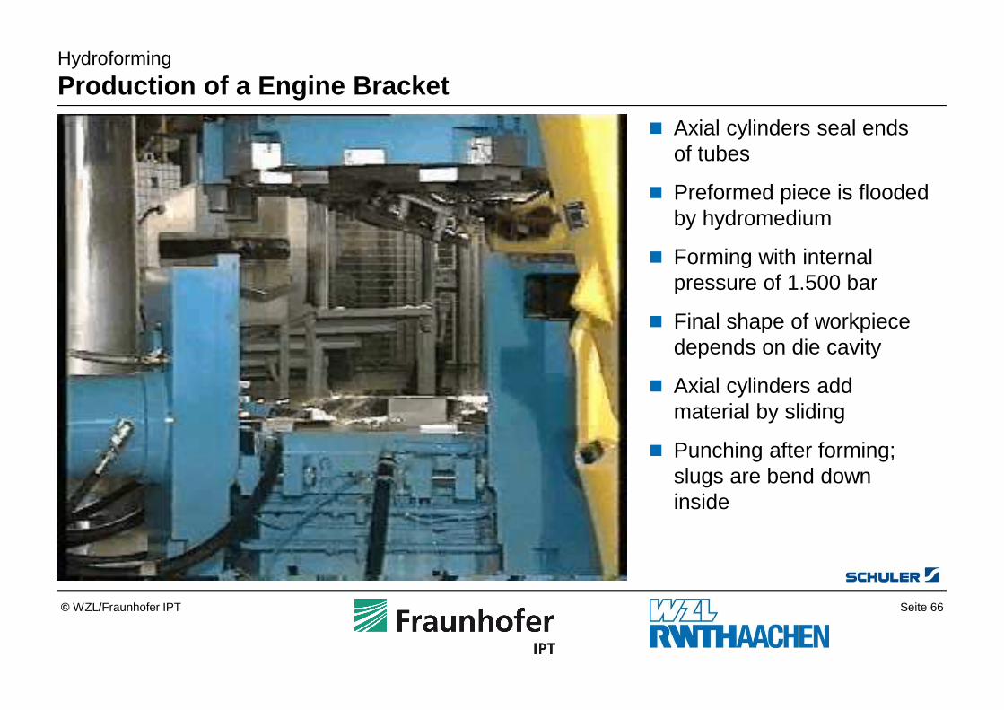
Hydroforming
Production of a Engine Bracket
� Axial cylinders seal ends of tubes
� Preformed piece is flooded by hydromedium
� Forming with internal pressure of 1.500 bar
� Final shape of workpiece depends on die cavity
� Axial cylinders add material by sliding
� Punching after forming; slugs are bend down inside
Seite 67© WZL/Fraunhofer IPT
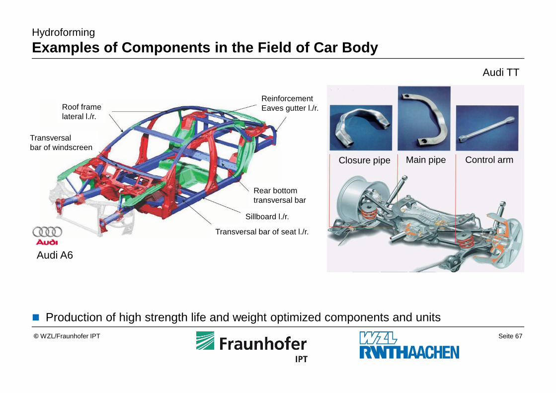
Hydroforming
Examples of Components in the Field of Car Body
Audi A6
Closure pipe Main pipe Control arm
Audi TT
� Production of high strength life and weight optimized components and units
Roof framelateral l./r.
Transversal bar of windscreen
Transversal bar of seat l./r.
Rear bottom transversal bar
Sillboard l./r.
ReinforcementEaves gutter l./r.


![[Engelberg] Compressive Sensing](https://img.pdfslide.us/doc/110x75/55cf9985550346d0339dc8ee/engelberg-compressive-sensing.jpg)