Embed Size (px)
Citation preview

Sheath Induced Over-Voltage Characteristic in 220 kV Power Cable Under Lightning Over-Voltage
Boyi Li1, Houkun Cui1, Zengjun An1, Haoran Rui2,* and Tao Zhao2 1 State Grid Jiangsu Electric Power Company Economic Research Institute, P.R. China
2Hebei Provincial Key Laboratory of Power Transmission Equipment Security Defense, North China Electric Power University, P. R. China
*Corresponding author Abstract—In order to limit the induced voltage, 220kV high voltage single core power cable needs reliable grounding in the actual operation. Metal sheath will produce induction overvoltage when lightning intrudes the cable conductor. Inductive overvoltages can have a variety of adverse effects on cable performance. Through the lightning intrusion of single-core cable core conductor typical simulation of the situation, the influence of the cable arrangement, the distance between the shafts, the length of the cable, magnitude and character of cable loads on the overvoltage are studied. Simulation and discussion indicate that cable arrangement, the distance between the shafts, the length of the cable, magnitude and character of cable loads have different degrees of influence on metal sheath overvoltage.
Keywords-single core cable; metal sheath; lightning over-voltage; EMTP
I. INTRODUCTION
With the vigorous development of the global electric power industry and the diversiform forms of energy transmission, the various types of cables have been applied widely. Owing to the large transmission capacity, mature manufacturing process, high stability and security, XLPE cables have been used abroad [1,2]. Considering the over-voltage of the point of ungrounded and cross-bonding in metal sheath, it is necessary to install the protector [3]. According to the "High-Voltage Cable Selection Guide Rule", the lightning impulse withstand voltage in external sheath of 220kV cable is 47.5kV [4].
II. SIMULATION MODEL ESTABLISHMENT
When the overhead line occurs shielding failure, both cable core and sheath layer will appear over-voltage [5]. The object for this research is 127 / 220kV XLPE power cable, and the finished cable is approximately 145.8mm in diameter. The cable size is shown in Table 1. Transmission lines are equipped with line-type arrester, when the line over-voltage affects, the arrester will be the action, and residual voltage after the arrester acting is the over-voltage amplitude of cable conductor. To study the worst case, a bevel wave is used to simulate the waveform of the lightning over-voltage [6,7]. The 520kV residual voltage value of the operative zinc oxide arrester, which has 10kA nominal discharge current, is set as a lightning power. The waveform which has 8 us wavefront time and 20 us half peak time is angle wave. The simulation circuit model is shown in Figure 1 and Figure 2 [8,9].
TABLE I. THE CABLE PARAMETERS
Sectional area/mm2 2000
Conductor OD /m 0.0275
Sheath ID /m 0.0651
Sheath OD /m 0.0679
Cable OD /m 0.0729
Conductor resistivity /ohm*m 1.75E-8
Metal sheath resistivity / ohm*m 2.83E-8
Insulation relative dielectric constant 2.3
Conductor, sheath, insulation relative permeability 1
FIGURE I. METAL SHEATH SINGLE-ENDED GROUNDING
FIGURE II. METAL SHEATH CROSS-CONNECTED DOUBLE-ENDED
GROUNDING
Figure 1 shows the metal sheathed single-ended grounding. Figure 2 presents the metal sheath cross-bonding double-ended grounding. Using LCC module to build simulation circuit, and Jmarti frequency cable model is used in this paper [10]. Jmarti frequency variation model in the transient calculation with R-C network to approximate the frequency-dependent impedance has high calculation accuracy. The cross-bonding grounding is divided into 3 segments, each of which has the same parameter options.
III. ANALYSIS OF INFLUENCING FACTORS
Cable arrangement, the length of each cable, the distance
2nd International Conference on Electrical, Automation and Mechanical Engineering (EAME 2017)
Copyright © 2017, the Authors. Published by Atlantis Press. This is an open access article under the CC BY-NC license (http://creativecommons.org/licenses/by-nc/4.0/).
Advances in Engineering Research, volume 86
48

between the shaft, with no load and the nature of the load have different degrees of impact on the metal sheath induction over-voltage. We will discuss below.
A. Cable Arrangement
Cable arrangement in different ways, there is a big difference in sheath layer inductive over voltage. In the simulation calculation. Respectively, the use of horizontal, vertical, type and close to the type of arrangement, buried depth of 1m, the distance between the shafts is 0.35m, the arrangement of the cable is shown in Figure 3.
Air
Soil
Horizontal arrangement
Vertical arrangement
Typearrangement
Close type arrangement
FIGURE III. CABLE ARRANGEMENT
The length of single-ended grounding cable is 300m; The length of cross-bonding double-ended grounding cable is 900m, the two transitions are used to divided the whole cable into 3 segments, other conditions are identical. Table 2 shows the maximum permutation voltage over the four arrangement modes.
TABLE II. THE INFLUENCE OF THE ARRANGEMENT ON THE OVERTAGE OF THE SHEATH
Cable Arrangement
Sheath Overvoltage Maximum(kV)
Single-ended grounding
Cross-bonding double-ended grounded
point of First cross-bonding
point of Second cross-bonding
horizontal 44.087 47.593 60.023 vertical 44.040 50.849 63.432
type 43.602 53.717 68.615 close type 40.398 45.553 69.450
According to the simulation results, the metal sheath with single-ended grounding, the inductive overvoltage of horizontal arrangement and vertical arrangement are similar, of type arrangement is small, of close type arrangement is smallest. If the use of cross-bonding grounding, the overvoltage occurs multiple fold at the displacement point, there is no clear relationship between the induced overvoltages and the cables arrangement; The overvoltage of the metal sheath varies with arrangement of the cable; The cross-bongding point which is from the power supply side induces the overvoltage is greater than that which is close to the cross-bonding point of the power supply side.
B. Cable Length
Power cable laying different length, over-voltage transmission process will occur in different degrees of
attenuation, there is a big difference in sheath over-voltage. The power cables are arranged in a horizontal arrangement, when the length of cable is 300m, 500m, 1000m, the overvoltage of metal sheath is shown in Table 3.
TABLE III. THE INFLUENCE OF THE LENGTH ON THE OVERTAGE OF THE SHEATH
Cable Length(m)
Sheath Overvoltage Maximum(kV)
Single-ended grounding
Cross-bonding double-ended grounded point of First cross-bonding
point of Second cross-bonding
300 44.087 47.593 60.023 500 83.087 57.991 84.662 1000 147.542 95.815 82.884
According to the table 3, the overvoltage of the metal sheath varies with length of the cable. The metal sheath with single-ended grounding, the induced overvoltage increases with the cable length increases. If the use of cross-bonding grounding, the overvoltage occurs multiple fold at the displacement point, and the three-phase overvoltage maximum does not appear at the same time, so the relationship between the overvoltage peak and the cable length is not obvious.
C. Distance between Axes
It’s necessary to consider the requirements about electrical, mechanical, transportation, manufacturing When the cable is laying [10]. This section mainly studies the length of the power cable is 300m, when using horizontal laying, the influence of the distance between the axes on the overvoltage of the sheath.
TABLE IV. THE INFLUENCE OF THE AXES ON THE OVERTAGE OF THE SHEATH
Distance Between Axes
(m)
Sheath Overvoltage Maximum(kV)
Single-ended grounding
Cross-bonding double-ended grounded
point of First cross-bonding
point of Second cross-
bonding 0.15 40.432 56.547 66.202 0.25 41.258 42.922 62.126 0.35 52.118 47.664 60.217
According to the simulation results we can see that, the use of different distance between the axes, there is a big difference on over-voltage of metal sheath. The metal sheath with single-ended grounding, the distance between the axes increases, the first terminal over-voltage also increases. If the use of cross-bonding grounding, the distance between the axes is different, the overvoltage amplitude and waveform will change, there is no clear relationship between the overvoltage of the sheath and the distance between the axes.
D. Magnitude and Character of Cable Loads
The power system has a variety of operating modes, power cables connected with different sizes, nature of the load. Therefore, it is necessary to study the power cable with load or no load, load nature of the impact on over-voltage. The power cables are arranged in a horizontal arrangement, the length of
Advances in Engineering Research, volume 86
49
cable is 300m, the distance between axes is 0.35m, other simulation conditions remain unchanged.
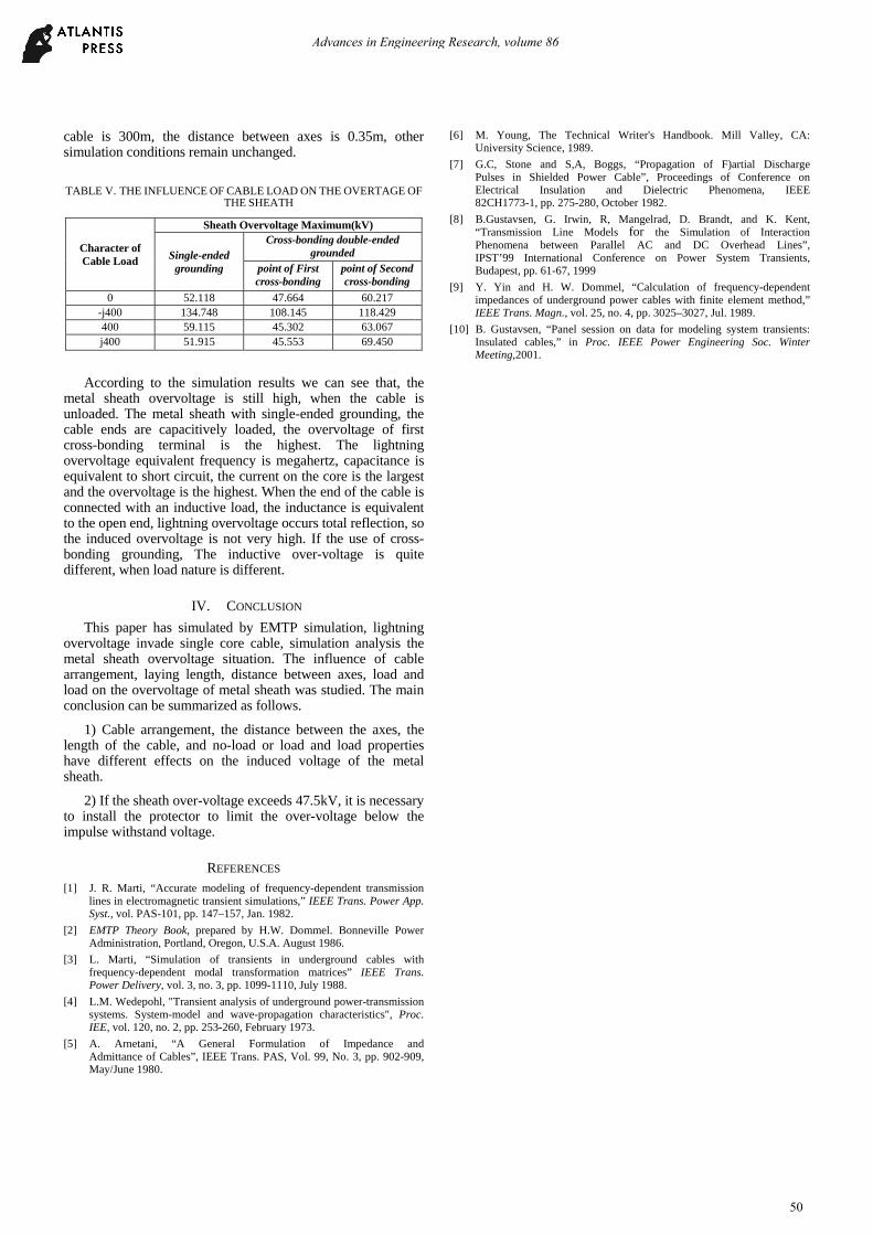
TABLE V. THE INFLUENCE OF CABLE LOAD ON THE OVERTAGE OF THE SHEATH
Character of Cable Load
Sheath Overvoltage Maximum(kV)
Single-ended grounding
Cross-bonding double-ended grounded
point of First cross-bonding
point of Second cross-bonding
0 52.118 47.664 60.217 -j400 134.748 108.145 118.429 400 59.115 45.302 63.067 j400 51.915 45.553 69.450
According to the simulation results we can see that, the metal sheath overvoltage is still high, when the cable is unloaded. The metal sheath with single-ended grounding, the cable ends are capacitively loaded, the overvoltage of first cross-bonding terminal is the highest. The lightning overvoltage equivalent frequency is megahertz, capacitance is equivalent to short circuit, the current on the core is the largest and the overvoltage is the highest. When the end of the cable is connected with an inductive load, the inductance is equivalent to the open end, lightning overvoltage occurs total reflection, so the induced overvoltage is not very high. If the use of cross-bonding grounding, The inductive over-voltage is quite different, when load nature is different.
IV. CONCLUSION
This paper has simulated by EMTP simulation, lightning overvoltage invade single core cable, simulation analysis the metal sheath overvoltage situation. The influence of cable arrangement, laying length, distance between axes, load and load on the overvoltage of metal sheath was studied. The main conclusion can be summarized as follows.
1) Cable arrangement, the distance between the axes, the length of the cable, and no-load or load and load properties have different effects on the induced voltage of the metal sheath.
2) If the sheath over-voltage exceeds 47.5kV, it is necessary to install the protector to limit the over-voltage below the impulse withstand voltage.
REFERENCES [1] J. R. Marti, “Accurate modeling of frequency-dependent transmission
lines in electromagnetic transient simulations,” IEEE Trans. Power App. Syst., vol. PAS-101, pp. 147–157, Jan. 1982.
[2] EMTP Theory Book, prepared by H.W. Dommel. Bonneville Power Administration, Portland, Oregon, U.S.A. August 1986.
[3] L. Marti, “Simulation of transients in underground cables with frequency-dependent modal transformation matrices” IEEE Trans. Power Delivery, vol. 3, no. 3, pp. 1099-1110, July 1988.
[4] L.M. Wedepohl, "Transient analysis of underground power-transmission systems. System-model and wave-propagation characteristics", Proc. IEE, vol. 120, no. 2, pp. 253-260, February 1973.
[5] A. Arnetani, “A General Formulation of Impedance and Admittance of Cables”, IEEE Trans. PAS, Vol. 99, No. 3, pp. 902-909, May/June 1980.
[6] M. Young, The Technical Writer's Handbook. Mill Valley, CA: University Science, 1989.
[7] G.C, Stone and S,A, Boggs, “Propagation of F)artial Discharge Pulses in Shielded Power Cable”, Proceedings of Conference on Electrical Insulation and Dielectric Phenomena, IEEE 82CH1773-1, pp. 275-280, October 1982.
[8] B.Gustavsen, G. Irwin, R, Mangelrad, D. Brandt, and K. Kent, “Transmission Line Models for the Simulation of Interaction Phenomena between Parallel AC and DC Overhead Lines”, IPST’99 International Conference on Power System Transients, Budapest, pp. 61-67, 1999
[9] Y. Yin and H. W. Dommel, “Calculation of frequency-dependent impedances of underground power cables with finite element method,” IEEE Trans. Magn., vol. 25, no. 4, pp. 3025–3027, Jul. 1989.
[10] B. Gustavsen, “Panel session on data for modeling system transients: Insulated cables,” in Proc. IEEE Power Engineering Soc. Winter Meeting,2001.
Advances in Engineering Research, volume 86
50