Embed Size (px)
Citation preview
Shear Walls 1
• Load Distribution to Shear Walls
• Shear wall stiffness
• Diaphragm types
• Types of Masonry Shear Walls
• Maximum Reinforcement Requirements
• Shear Strength
• Example: Single Layer Reinforcing
• Example: Distributed Reinforcing
• Example: Flanged Walls
Shear Walls
Shear Walls 2
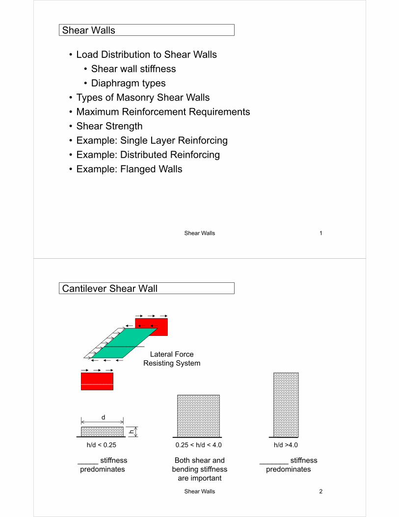
_____ stiffness predominates
_______ stiffness predominates
Both shear and bending stiffness
are important
d
h
h/d < 0.25 0.25 < h/d < 4.0 h/d >4.0
__________
___________
Lateral Force Resisting System
Cantilever Shear Wall
Shear Walls 3
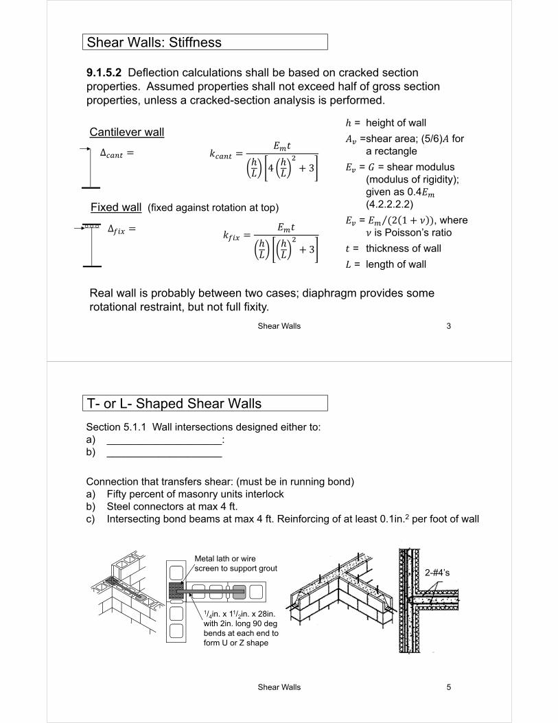
9.1.5.2 Deflection calculations shall be based on cracked section properties. Assumed properties shall not exceed half of gross section properties, unless a cracked-section analysis is performed.
Cantilever wallℎ = height of wall
𝐴 =shear area; (5/6)𝐴 for a rectangle
𝐸 = 𝐺 = shear modulus (modulus of rigidity); given as 0.4𝐸(4.2.2.2.2)
𝐸 = 𝐸 2 1 𝜈⁄ , where 𝜈 is Poisson’s ratio
𝑡 = thickness of wall
𝐿 = length of wall
Fixed wall (fixed against rotation at top)
Real wall is probably between two cases; diaphragm provides some rotational restraint, but not full fixity.
Shear Walls: Stiffness
𝑘𝐸 𝑡
ℎ𝐿 4
ℎ𝐿 3
𝑘𝐸 𝑡
ℎ𝐿
ℎ𝐿 3
Δ
Δ
Shear Walls 5
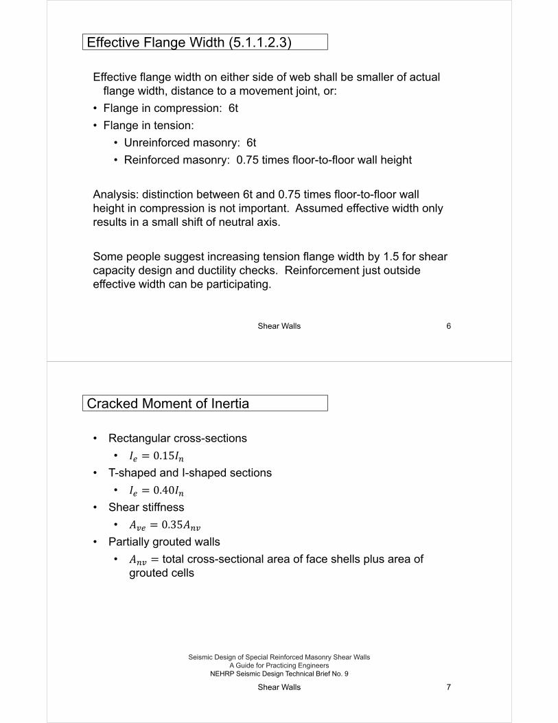
Section 5.1.1 Wall intersections designed either to:a) ____________________: b) ____________________
Connection that transfers shear: (must be in running bond)a) Fifty percent of masonry units interlockb) Steel connectors at max 4 ft.c) Intersecting bond beams at max 4 ft. Reinforcing of at least 0.1in.2 per foot of wall
2-#4’s
Metal lath or wire screen to support grout
1/4in. x 11/2in. x 28in. with 2in. long 90 deg bends at each end to form U or Z shape
T- or L- Shaped Shear Walls
Shear Walls 6
Effective flange width on either side of web shall be smaller of actual flange width, distance to a movement joint, or:
• Flange in compression: 6t
• Flange in tension:
• Unreinforced masonry: 6t
• Reinforced masonry: 0.75 times floor-to-floor wall height
Analysis: distinction between 6t and 0.75 times floor-to-floor wall height in compression is not important. Assumed effective width only results in a small shift of neutral axis.
Some people suggest increasing tension flange width by 1.5 for shear capacity design and ductility checks. Reinforcement just outside effective width can be participating.
Effective Flange Width (5.1.1.2.3)
Shear Walls 7
• Rectangular cross-sections
• 𝐼 0.15𝐼
• T-shaped and I-shaped sections
• 𝐼 0.40𝐼
• Shear stiffness
• 𝐴 0.35𝐴
• Partially grouted walls
• 𝐴 total cross-sectional area of face shells plus area of grouted cells
Cracked Moment of Inertia
Seismic Design of Special Reinforced Masonry Shear Walls A Guide for Practicing Engineers
NEHRP Seismic Design Technical Brief No. 9
Shear Walls 8
40in.
112i
n.6𝑡
=48
in.
56in
.
Elevation
Plan
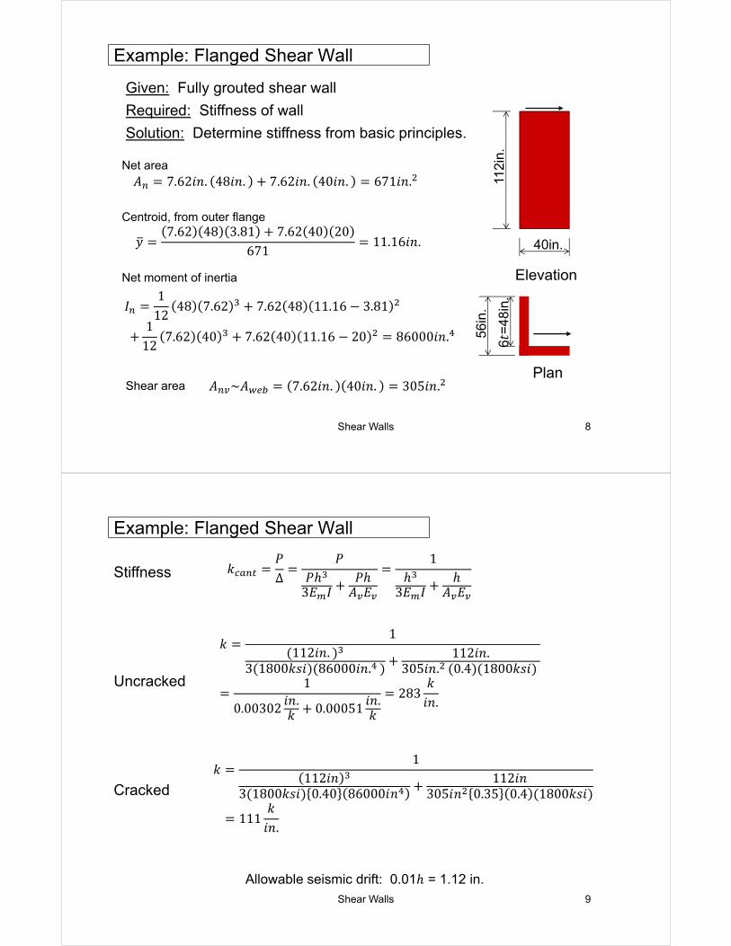
Given: Fully grouted shear wall
Required: Stiffness of wall
Solution: Determine stiffness from basic principles.
Centroid, from outer flange
Example: Flanged Shear Wall
Net area
Net moment of inertia
Shear area
𝐴 7.62𝑖𝑛. 48𝑖𝑛. 7.62𝑖𝑛. 40𝑖𝑛. 671𝑖𝑛.
𝑦7.62 48 3.81 7.62 40 20
67111.16𝑖𝑛.
𝐴 ~𝐴 7.62𝑖𝑛. 40𝑖𝑛. 305𝑖𝑛.
𝐼1
1248 7.62 7.62 48 11.16 3.81
112
7.62 40 7.62 40 11.16 20 86000𝑖𝑛.
Shear Walls 9
Example: Flanged Shear Wall
Uncracked
Cracked
𝑘1
112𝑖𝑛3 1800𝑘𝑠𝑖 0.40 86000𝑖𝑛
112𝑖𝑛305𝑖𝑛 0.35 0.4 1800𝑘𝑠𝑖
111𝑘
𝑖𝑛.
𝑘𝑃Δ
𝑃𝑃ℎ
3𝐸 𝐼𝑃ℎ
𝐴 𝐸
1ℎ
3𝐸 𝐼ℎ
𝐴 𝐸Stiffness
𝑘1
112𝑖𝑛.3 1800𝑘𝑠𝑖 86000𝑖𝑛.
112𝑖𝑛.305𝑖𝑛. 0.4 1800𝑘𝑠𝑖
1
0.00302𝑖𝑛.𝑘 0.00051
𝑖𝑛.𝑘
283𝑘
𝑖𝑛.
Allowable seismic drift: 0.01ℎ = 1.12 in.
Shear Walls 10
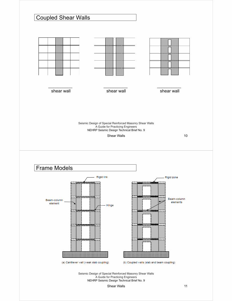
__________ shear wall
Coupled Shear Walls
Seismic Design of Special Reinforced Masonry Shear Walls A Guide for Practicing Engineers
NEHRP Seismic Design Technical Brief No. 9
__________ shear wall
__________ shear wall
Shear Walls 11
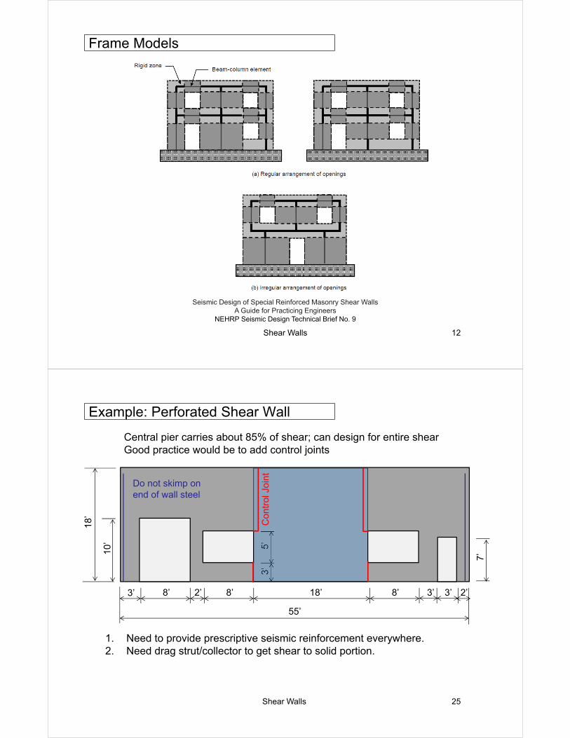
Frame Models
Seismic Design of Special Reinforced Masonry Shear Walls A Guide for Practicing Engineers
NEHRP Seismic Design Technical Brief No. 9
Shear Walls 12
Frame Models
Seismic Design of Special Reinforced Masonry Shear Walls A Guide for Practicing Engineers
NEHRP Seismic Design Technical Brief No. 9
Shear Walls 25
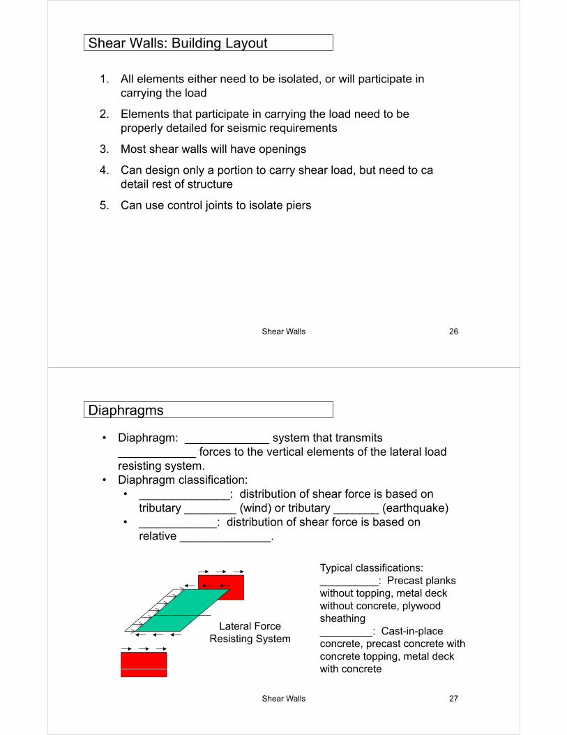
Example: Perforated Shear Wall
Central pier carries about 85% of shear; can design for entire shearGood practice would be to add control joints
10’
18’
5’3’
7’
55’
3’ 8’ 2’ 8’ 18’ 8’ 3’ 3’ 2’
1. Need to provide prescriptive seismic reinforcement everywhere.2. Need drag strut/collector to get shear to solid portion.
Do not skimp on end of wall steel
Con
trol
Joi
nt
Shear Walls 26
1. All elements either need to be isolated, or will participate in carrying the load
2. Elements that participate in carrying the load need to be properly detailed for seismic requirements
3. Most shear walls will have openings
4. Can design only a portion to carry shear load, but need to ca detail rest of structure
5. Can use control joints to isolate piers
Shear Walls: Building Layout
Shear Walls 27
• Diaphragm: _____________ system that transmits ____________ forces to the vertical elements of the lateral load resisting system.
• Diaphragm classification:• ______________: distribution of shear force is based on
tributary ________ (wind) or tributary _______ (earthquake)• ____________: distribution of shear force is based on
relative ______________.
__________
___________
Lateral Force Resisting System
Typical classifications:__________: Precast planks without topping, metal deck without concrete, plywood sheathing_________: Cast-in-place concrete, precast concrete with concrete topping, metal deck with concrete
Diaphragms
Shear Walls 28
Direct Shear:
Torsional Shear:
𝑉 = total shear force on building
𝑘 = relative rigidity of lateral force resisting element i
𝑑 = distance from center of stiffness
𝑒 = eccentricity of load from center of stiffness
Rigid Diaphragms
𝐹 𝑉𝑘
∑ 𝑘
𝐹 𝑉𝑒𝑘 𝑑
∑ 𝑘 𝑑
Total Shear on Wall: 𝐹 𝐹 𝐹
Shear Walls 29
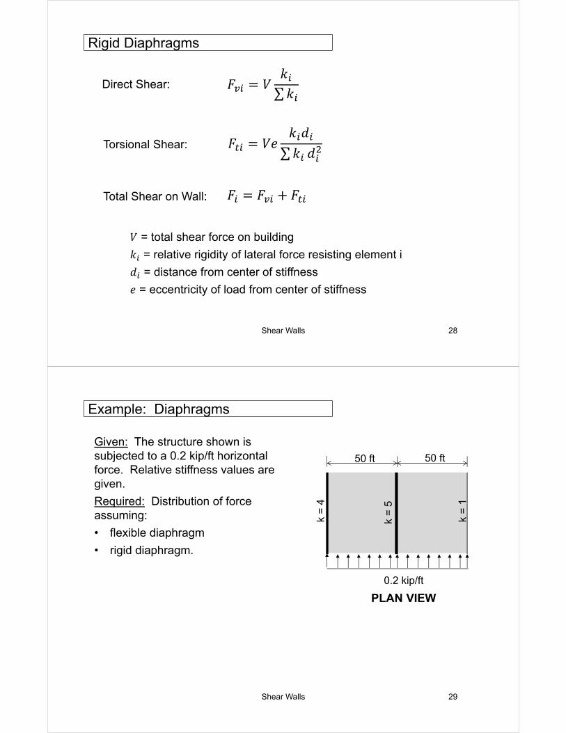
Given: The structure shown is subjected to a 0.2 kip/ft horizontal force. Relative stiffness values are given.
Required: Distribution of force assuming:
• flexible diaphragm
• rigid diaphragm.
k =
4
k =
5
k =
150 ft 50 ft
0.2 kip/ft
PLAN VIEW
Example: Diaphragms
Shear Walls 30
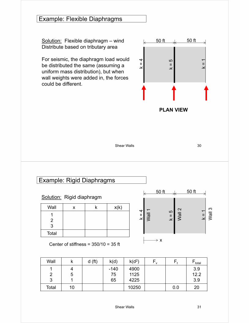
Solution: Flexible diaphragm – windDistribute based on tributary area
For seismic, the diaphragm load would be distributed the same (assuming a uniform mass distribution), but when wall weights were added in, the forces could be different.
k =
4
k =
5
k =
1
50 ft 50 ft
PLAN VIEW
Example: Flexible Diaphragms
Shear Walls 31
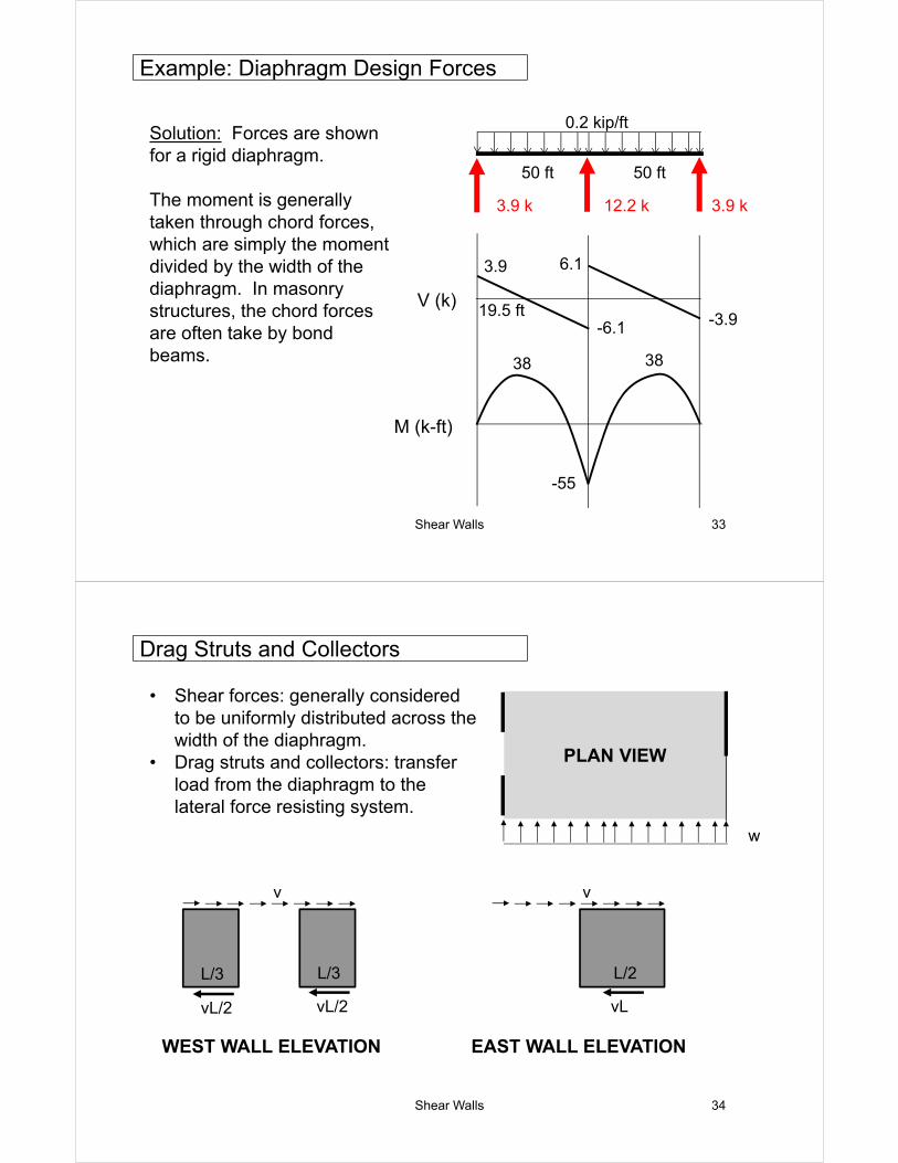
Solution: Rigid diaphragm
k =
4
k =
5
k =
1
50 ft 50 ft
Wal
l 1
Wal
l 2
Wal
l 3
x
Wall x k x(k)
123
Total
Center of stiffness = 350/10 = 35 ft
Wall k d (ft) k(d) k(d2) Fv Ft Ftotal
123
451
-1407565
490011254225
3.912.23.9
Total 10 10250 0.0 20
Example: Rigid Diaphragms
Shear Walls 33
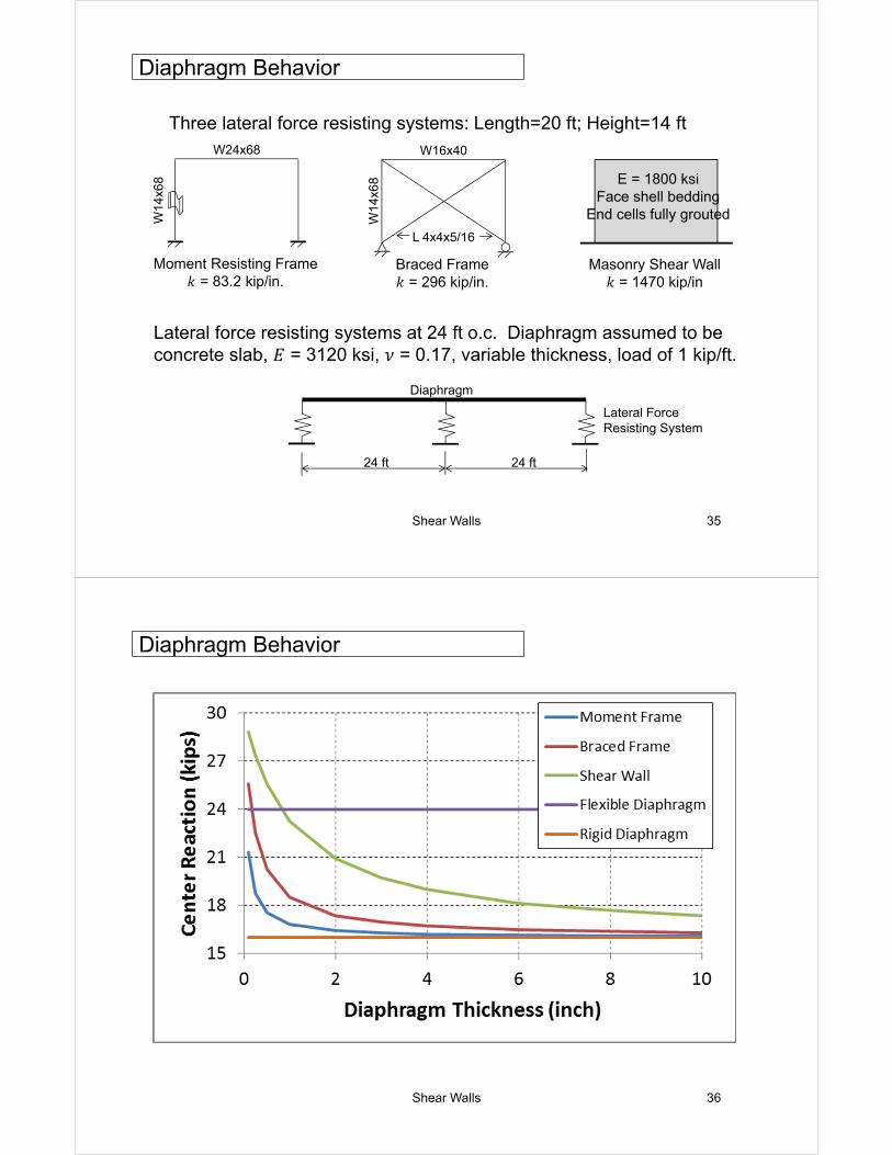
Solution: Forces are shown for a rigid diaphragm.
The moment is generally taken through chord forces, which are simply the moment divided by the width of the diaphragm. In masonry structures, the chord forces are often take by bond beams.
50 ft 50 ft
0.2 kip/ft
3.9 k 12.2 k 3.9 k
V (k)
M (k-ft)
3.9
-3.9
6.1
-6.1
38
19.5 ft
38
-55
Example: Diaphragm Design Forces
Shear Walls 34
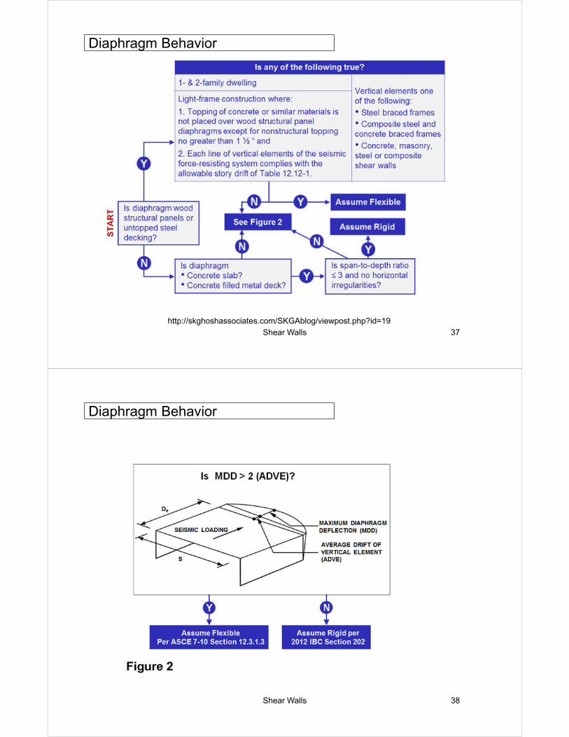
• Shear forces: generally considered to be uniformly distributed across the width of the diaphragm.
• Drag struts and collectors: transfer load from the diaphragm to the lateral force resisting system.
w
PLAN VIEW
v
vL/2 vL/2
WEST WALL ELEVATION
v
vL
EAST WALL ELEVATION
L/3 L/3 L/2
Drag Struts and Collectors
Shear Walls 35
Three lateral force resisting systems: Length=20 ft; Height=14 ftW24x68
W14
x68
Moment Resisting Frame𝑘 = 83.2 kip/in.
W16x40
W14
x68
Braced Frame𝑘 = 296 kip/in.
L 4x4x5/16
W16x40
Masonry Shear Wall𝑘 = 1470 kip/in
L 4x4x5/16
E = 1800 ksiFace shell bedding
End cells fully grouted
Lateral force resisting systems at 24 ft o.c. Diaphragm assumed to be concrete slab, 𝐸 = 3120 ksi, 𝜈 = 0.17, variable thickness, load of 1 kip/ft.
Diaphragm
Lateral Force Resisting System
24 ft 24 ft
Diaphragm Behavior
Shear Walls 36
Diaphragm Behavior
Shear Walls 37
http://skghoshassociates.com/SKGAblog/viewpost.php?id=19
Diaphragm Behavior
Shear Walls 38
Diaphragm Behavior
Shear Walls 39
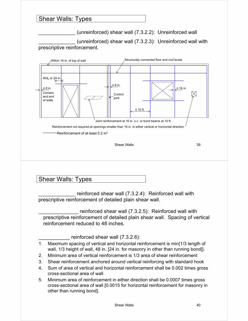
_____________ (unreinforced) shear wall (7.3.2.2): Unreinforced wall
_____________ (unreinforced) shear wall (7.3.2.3): Unreinforced wall with prescriptive reinforcement.
40db or 24 in.
Joint reinforcement at 16 in. o.c. or bond beams at 10 ft.
Reinforcement not required at openings smaller than 16 in. in either vertical or horizontal direction
≤ 16 in.
Control joint
≤ 8 in.
≤ 10 ft.
≤ 8 in.
Corners and end of walls
Within 16 in. of top of wall Structurally connected floor and roof levels
Reinforcement of at least 0.2 in2
Shear Walls: Types
Shear Walls 40
_____________ reinforced shear wall (7.3.2.4): Reinforced wall with prescriptive reinforcement of detailed plain shear wall.
______________ reinforced shear wall (7.3.2.5): Reinforced wall with prescriptive reinforcement of detailed plain shear wall. Spacing of vertical reinforcement reduced to 48 inches.
___________ reinforced shear wall (7.3.2.6):1. Maximum spacing of vertical and horizontal reinforcement is min{1/3 length of
wall, 1/3 height of wall, 48 in. [24 in. for masonry in other than running bond]}.2. Minimum area of vertical reinforcement is 1/3 area of shear reinforcement3. Shear reinforcement anchored around vertical reinforcing with standard hook4. Sum of area of vertical and horizontal reinforcement shall be 0.002 times gross
cross-sectional area of wall5. Minimum area of reinforcement in either direction shall be 0.0007 times gross
cross-sectional area of wall [0.0015 for horizontal reinforcement for masonry in other than running bond].
Shear Walls: Types
Shear Walls 41
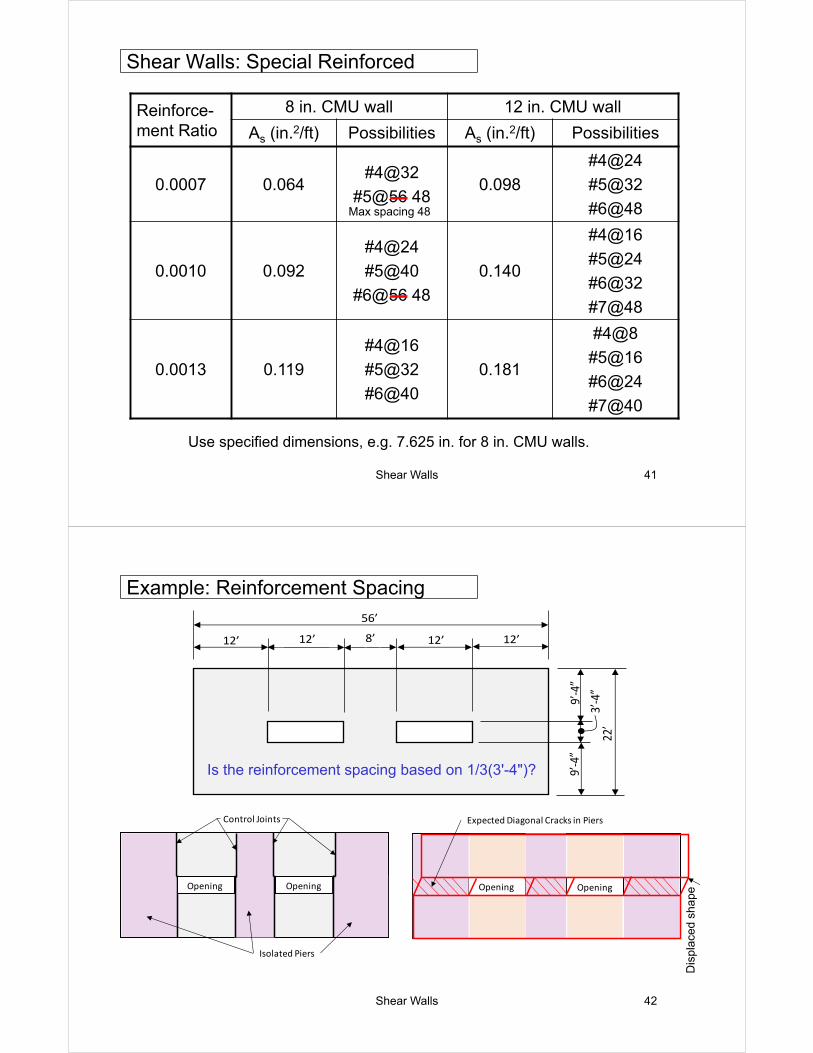
Use specified dimensions, e.g. 7.625 in. for 8 in. CMU walls.
Reinforce-ment Ratio
8 in. CMU wall 12 in. CMU wall
As (in.2/ft) Possibilities As (in.2/ft) Possibilities
0.0007 0.064#4@32
#5@56 480.098
#4@24
#5@32
#6@48
0.0010 0.092
#4@24
#5@40
#6@56 48
0.140
#4@16
#5@24
#6@32
#7@48
0.0013 0.119
#4@16
#5@32
#6@40
0.181
#4@8
#5@16
#6@24
#7@40
Shear Walls: Special Reinforced
Max spacing 48
Shear Walls 42
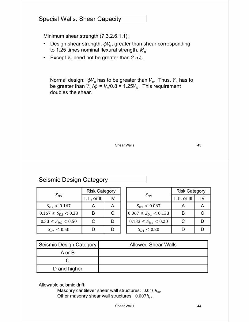
Example: Reinforcement Spacing56’
12’ 12’ 8’ 12’ 12’
9’‐4”
22’
9’‐4”
3’‐4”
Opening Opening
Control Joints
Isolated Piers
Expected Diagonal Cracks in Piers
OpeningOpening
Dis
plac
ed s
hape
Is the reinforcement spacing based on 1/3(3ʹ-4ʺ)?
Shear Walls 43
Minimum shear strength (7.3.2.6.1.1):
• Design shear strength, 𝜙𝑉 , greater than shear corresponding to 1.25 times nominal flexural strength, 𝑀
• Except 𝑉 need not be greater than 2.5𝑉 .
Normal design: 𝜙𝑉𝑛 has to be greater than 𝑉𝑢. Thus, 𝑉𝑛 has to be greater than 𝑉𝑢/𝜙 = Vu/0.8 = 1.25𝑉𝑢. This requirement doubles the shear.
Special Walls: Shear Capacity
Shear Walls 44
𝑆Risk Category
I, II, or III IV
𝑆 0.167 A A
0.167 𝑆 0.33 B C
0.33 𝑆 0.50 C D
𝑆 0.50 D D
Seismic Design Category
𝑆Risk Category
I, II, or III IV
𝑆 0.067 A A
0.067 𝑆 0.133 B C
0.133 𝑆 0.20 C D
𝑆 0.20 D D
Seismic Design Category Allowed Shear Walls
A or B
C
D and higher
Allowable seismic drift:Masonry cantilever shear wall structures: 0.010ℎOther masonry shear wall structures: 0.007ℎ
Shear Walls 45
Response modification factor, 𝑅:Seismic design force divided by response modification factor, which accounts for ductility and energy absorption.
Deflection amplification factor, 𝐶 :Deflection under seismic design loads multiplied by deflection amplification factor.
Shear WallBearing Wall System Building Frame System
𝑅 𝐶 𝑅 𝐶
Ordinary plain 1 ½ 1 ¼ 1 ½ 1 ¼
Detailed plain 2 1 ¾ 2 1 ¾
Ordinary reinforced
2 1 ¾ 2 1 ¾
Intermediate reinforced
3 ½ 2 ¼ 4 4
Special reinforced
5 3 ½ 5 ½ 4 ½
Seismic Design Category
Shear Walls 46
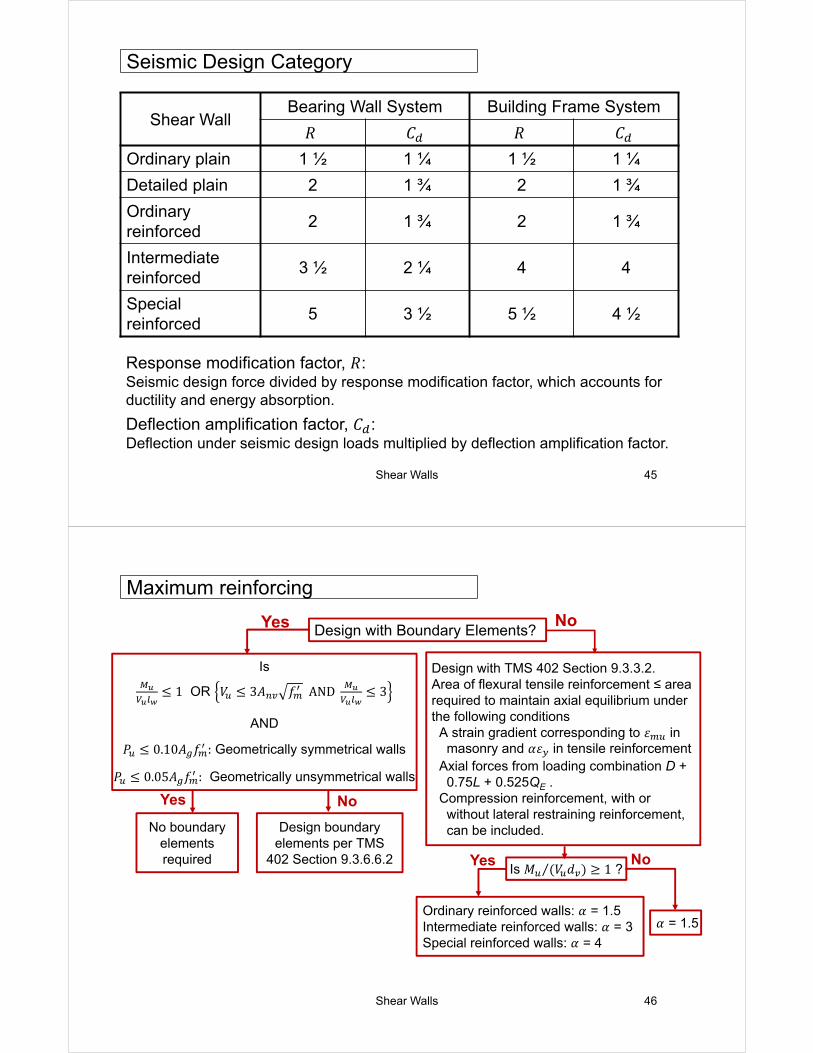
Maximum reinforcing
Design with Boundary Elements?No
Is
1 OR 𝑉 3𝐴 𝑓 AND 3
AND
𝑃 0.10𝐴 𝑓 : Geometrically symmetrical walls
𝑃 0.05𝐴 𝑓 : Geometrically unsymmetrical walls
No boundary elements required
Design boundary elements per TMS
402 Section 9.3.6.6.2
Design with TMS 402 Section 9.3.3.2.Area of flexural tensile reinforcement ≤ area required to maintain axial equilibrium under the following conditions
A strain gradient corresponding to 𝜀 in masonry and 𝛼𝜀 in tensile reinforcement
Axial forces from loading combination D + 0.75L + 0.525QE .
Compression reinforcement, with or without lateral restraining reinforcement, can be included.
Is 𝑀 𝑉 𝑑⁄ 1 ?
𝛼 = 1.5Ordinary reinforced walls: 𝛼 = 1.5Intermediate reinforced walls: 𝛼 = 3Special reinforced walls: 𝛼 = 4
Yes No
Yes
Yes No
Shear Walls 48
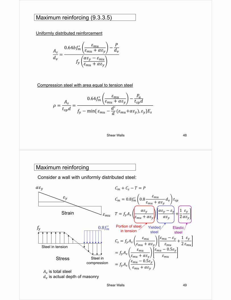
Maximum reinforcing (9.3.3.5)
𝜌𝐴
𝑡 𝑑
0.64𝑓𝜀
𝜀 𝛼𝜀𝑃
𝑡 𝑑
𝑓 min 𝜀 𝑑𝑑 𝜀 𝛼𝜀 , 𝜀 𝐸
Compression steel with area equal to tension steel
Uniformly distributed reinforcement
𝐴𝑑
0.64𝑏𝑓𝜀
𝜀 𝛼𝜀𝑃𝑑
𝑓𝛼𝜀 𝜀𝜀 𝛼𝜀
Shear Walls 49
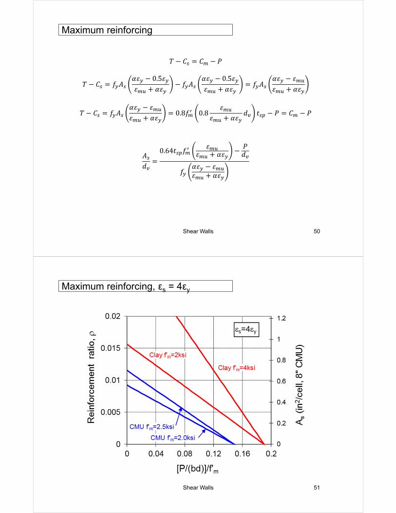
Consider a wall with uniformly distributed steel:
Strain
𝛼𝜀
Stress
Steel in tension
Steel in compression
0.8𝑓
𝐴 is total steel𝑑 is actual depth of masonry
Portion of steel in tension
Yielded steel
Elastic steel
Maximum reinforcing
𝜀
𝜀
𝑓
𝐶 𝐶 𝑇 𝑃
𝐶 0.8𝑓 0.8𝜀
𝜀 𝛼𝜀𝑑 𝑡
𝑇 𝑓 𝐴𝛼𝜀
𝜀 𝛼𝜀𝛼𝜀 𝜀
𝛼𝜀12
𝜀𝛼𝜀
𝐶 𝑓 𝐴𝜀
𝜀 𝛼𝜀𝜀 𝜀
𝜀12
𝜀𝜀
𝑓 𝐴𝜀
𝜀 𝛼𝜀𝜀 0.5𝜀
𝜀
𝑓 𝐴𝜀 0.5𝜀𝜀 𝛼𝜀
Shear Walls 50
Maximum reinforcing
𝑇 𝐶 𝐶 𝑃
𝑇 𝐶 𝑓 𝐴𝛼𝜀 0.5𝜀𝜀 𝛼𝜀
𝑓 𝐴𝛼𝜀 0.5𝜀𝜀 𝛼𝜀
𝑓 𝐴𝛼𝜀 𝜀𝜀 𝛼𝜀
𝑇 𝐶 𝑓 𝐴𝛼𝜀 𝜀𝜀 𝛼𝜀
0.8𝑓 0.8𝜀
𝜀 𝛼𝜀𝑑 𝑡 𝑃 𝐶 𝑃
𝐴𝑑
0.64𝑡 𝑓𝜀
𝜀 𝛼𝜀𝑃𝑑
𝑓𝛼𝜀 𝜀𝜀 𝛼𝜀
Shear Walls 51
Maximum reinforcing, εs = 4εy
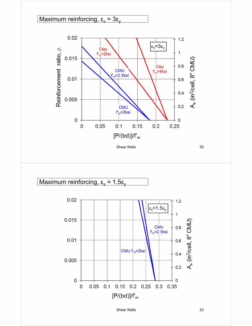
Shear Walls 52
Maximum reinforcing, εs = 3εy
Shear Walls 53
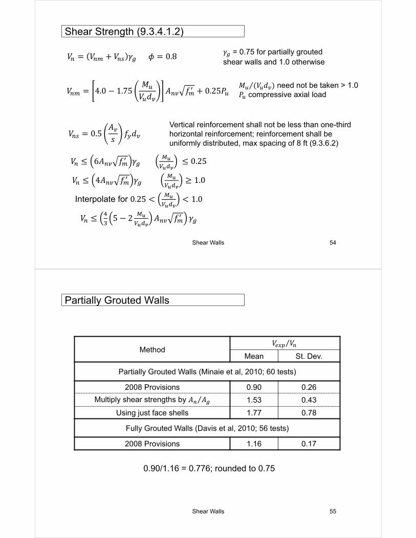
Maximum reinforcing, εs = 1.5εy
Shear Walls 54
Vertical reinforcement shall not be less than one-third horizontal reinforcement; reinforcement shall be uniformly distributed, max spacing of 8 ft (9.3.6.2)
𝑀 𝑉 𝑑⁄ need not be taken > 1.0𝑃 compressive axial load
𝛾 = 0.75 for partially grouted shear walls and 1.0 otherwise
Shear Strength (9.3.4.1.2)
𝑉 6𝐴 𝑓 𝛾 0.25
𝑉 4𝐴 𝑓 𝛾 1.0
Interpolate for 0.25 1.0
𝑉 5 2 𝐴 𝑓 𝛾
𝑉 𝑉 𝑉 𝛾 𝜙 0.8
𝑉 4.0 1.75𝑀
𝑉 𝑑𝐴 𝑓 0.25𝑃
𝑉 0.5𝐴𝑠
𝑓 𝑑
Shear Walls 55
Method𝑉 𝑉⁄
Mean St. Dev.
Partially Grouted Walls (Minaie et al, 2010; 60 tests)
2008 Provisions 0.90 0.26
Multiply shear strengths by 𝐴 𝐴⁄ 1.53 0.43
Using just face shells 1.77 0.78
Fully Grouted Walls (Davis et al, 2010; 56 tests)
2008 Provisions 1.16 0.17
0.90/1.16 = 0.776; rounded to 0.75
Partially Grouted Walls
Shear Walls 57
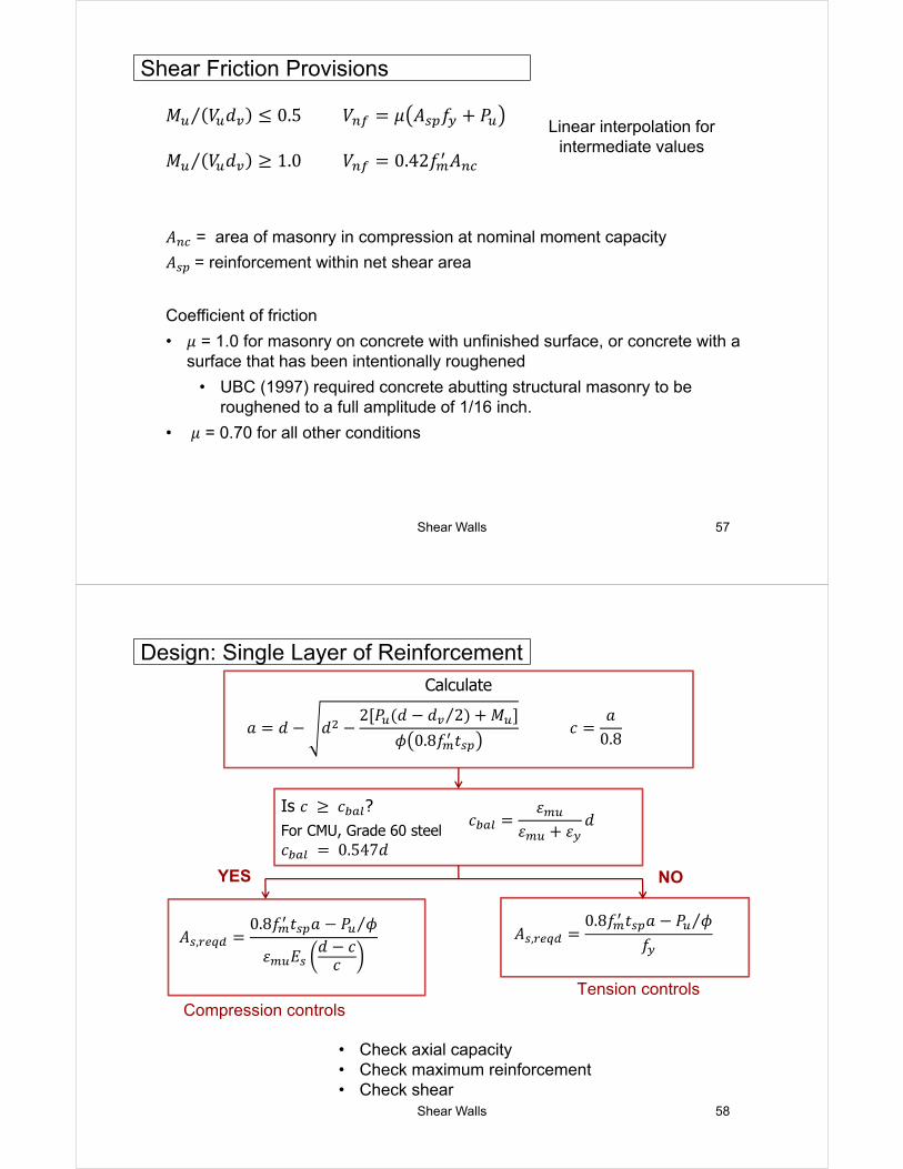
Shear Friction Provisions
𝐴 = area of masonry in compression at nominal moment capacity
𝐴 = reinforcement within net shear area
Coefficient of friction
• 𝜇 = 1.0 for masonry on concrete with unfinished surface, or concrete with a surface that has been intentionally roughened
• UBC (1997) required concrete abutting structural masonry to be roughened to a full amplitude of 1/16 inch.
• 𝜇 = 0.70 for all other conditions
𝑀 𝑉 𝑑 0.5⁄ 𝑉 𝜇 𝐴 𝑓 𝑃
𝑀 𝑉 𝑑⁄ 1.0 𝑉 0.42𝑓 𝐴
Linear interpolation for intermediate values
Shear Walls 58
• Check axial capacity• Check maximum reinforcement• Check shear
Design: Single Layer of ReinforcementCalculate
Is 𝑐 𝑐 ?For CMU, Grade 60 steel𝑐 0.547𝑑
YES
Compression controlsTension controls
NO
𝑎 𝑑 𝑑2 𝑃 𝑑 𝑑 2 𝑀⁄
𝜙 0.8𝑓 𝑡 𝑐
𝑎0.8
𝑐𝜀
𝜀 𝜀𝑑
𝐴 ,0.8𝑓 𝑡 𝑎 𝑃 𝜙⁄
𝜀 𝐸𝑑 𝑐
𝑐
𝐴 ,0.8𝑓 𝑡 𝑎 𝑃 𝜙⁄
𝑓
Shear Walls 59
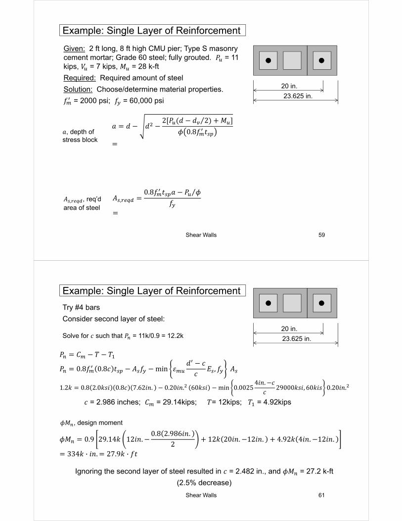
Given: 2 ft long, 8 ft high CMU pier; Type S masonry cement mortar; Grade 60 steel; fully grouted. 𝑃 = 11 kips, 𝑉 = 7 kips, 𝑀 = 28 k-ft
Required: Required amount of steel
Solution: Choose/determine material properties.
𝑓 = 2000 psi; 𝑓 = 60,000 psi
20 in.
23.625 in.
Example: Single Layer of Reinforcement
𝑎, depth of stress block
𝐴 , , req’darea of steel
𝑎 𝑑 𝑑2 𝑃 𝑑 𝑑 2 𝑀⁄
𝜙 0.8𝑓 𝑡
𝐴 ,0.8𝑓 𝑡 𝑎 𝑃 𝜙⁄
𝑓
Shear Walls 61
20 in.
23.625 in.
Try #4 bars
Consider second layer of steel:
𝑐 = 2.986 inches; 𝐶 = 29.14kips; 𝑇= 12kips; 𝑇 = 4.92kips
Example: Single Layer of Reinforcement
Solve for 𝑐 such that 𝑃 = 11k/0.9 = 12.2k
𝜙𝑀 , design moment
Ignoring the second layer of steel resulted in 𝑐 = 2.482 in., and 𝜙𝑀 = 27.2 k-ft
(2.5% decrease)
𝑃 𝐶 𝑇 𝑇
𝑃 0.8𝑓 0.8𝑐 𝑡 𝐴 𝑓 min 𝜀𝑑 𝑐
𝑐𝐸 , 𝑓 𝐴
1.2𝑘 0.8 2.0𝑘𝑠𝑖 0.8𝑐 7.62𝑖𝑛. 0.20𝑖𝑛. 60𝑘𝑠𝑖 min 0.00254𝑖𝑛. 𝑐
𝑐29000𝑘𝑠𝑖, 60𝑘𝑖𝑠 0.20𝑖𝑛.
𝜙𝑀 0.9 29.14𝑘 12𝑖𝑛.0.8 2.986𝑖𝑛.
212𝑘 20𝑖𝑛. 12𝑖𝑛. 4.92𝑘 4𝑖𝑛. 12𝑖𝑛.
334𝑘 · 𝑖𝑛. 27.9𝑘 · 𝑓𝑡
Shear Walls 62
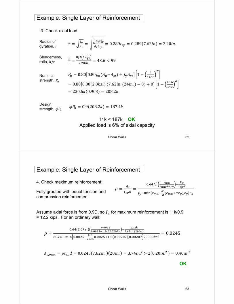
3. Check axial load
11k < 187k OKApplied load is 6% of axial capacity
Example: Single Layer of Reinforcement
Radius of gyration, 𝑟
Slenderness, ratio, ℎ/𝑟
Nominal strength, 𝑃
Design strength, 𝜙𝑃
𝑟 0.289𝑡 0.289 7.62𝑖𝑛 2.20𝑖𝑛.
.
. .43.6 99
𝑃 0.80 0.80𝑓 𝐴 𝐴 𝑓 𝐴 1
0.80 0.80 2.0𝑘𝑠𝑖 7.62𝑖𝑛. 24𝑖𝑛. 0 0 1.
230.6𝑘 0.903 208.2𝑘
𝜙𝑃 0.9 208.2𝑘 187.4𝑘
Shear Walls 63
4. Check maximum reinforcement:
Fully grouted with equal tension and compression reinforcement
Assume axial force is from 0.9D, so 𝑃 for maximum reinforcement is 11k/0.9 = 12.2 kips. For an ordinary wall:
Example: Single Layer of Reinforcement
𝜌.
,
𝜌. . .
. . . .
. . .
. ..
. . . , . 0.0245
𝐴 , 𝜌𝑡 𝑑 0.0245 7.62𝑖𝑛. 20𝑖𝑛. 3.74𝑖𝑛. 2 0.20𝑖𝑛. 0.40𝑖𝑛.
OK
Shear Walls 64
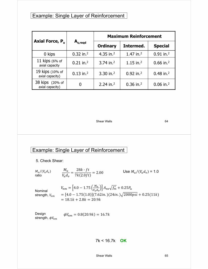
Axial Force, Pu As,reqd
Maximum Reinforcement
Ordinary Intermed. Special
0 kips 0.32 in.2 4.35 in.2 1.47 in.2 0.91 in.2
11 kips (6% of axial capacity
0.21 in.2 3.74 in.2 1.15 in.2 0.66 in.2
19 kips (10% of axial capacity)
0.13 in.2 3.30 in.2 0.92 in.2 0.48 in.2
38 kips (20% of axial capacity)
0 2.24 in.2 0.36 in.2 0.06 in.2
Example: Single Layer of Reinforcement
Shear Walls 65
5. Check Shear:
Use 𝑀 𝑉 𝑑⁄ = 1.0
Example: Single Layer of Reinforcement
𝑀 𝑉 𝑑⁄ratio
Nominal strength, 𝑉
Design strength, 𝜙𝑉
𝑀𝑉 𝑑
28𝑘 · 𝑓𝑡7𝑘 2.0𝑓𝑡
2.00
𝑉 4.0 1.75 𝐴 𝑓 0.25𝑃
4.0 1.75 1.0 7.62𝑖𝑛. 24𝑖𝑛. 2000𝑝𝑠𝑖 0.25 11𝑘18.1𝑘 2.8𝑘 20.9𝑘
𝜙𝑉 0.8 20.9𝑘 16.7𝑘
7k < 16.7k OK
Shear Walls 66
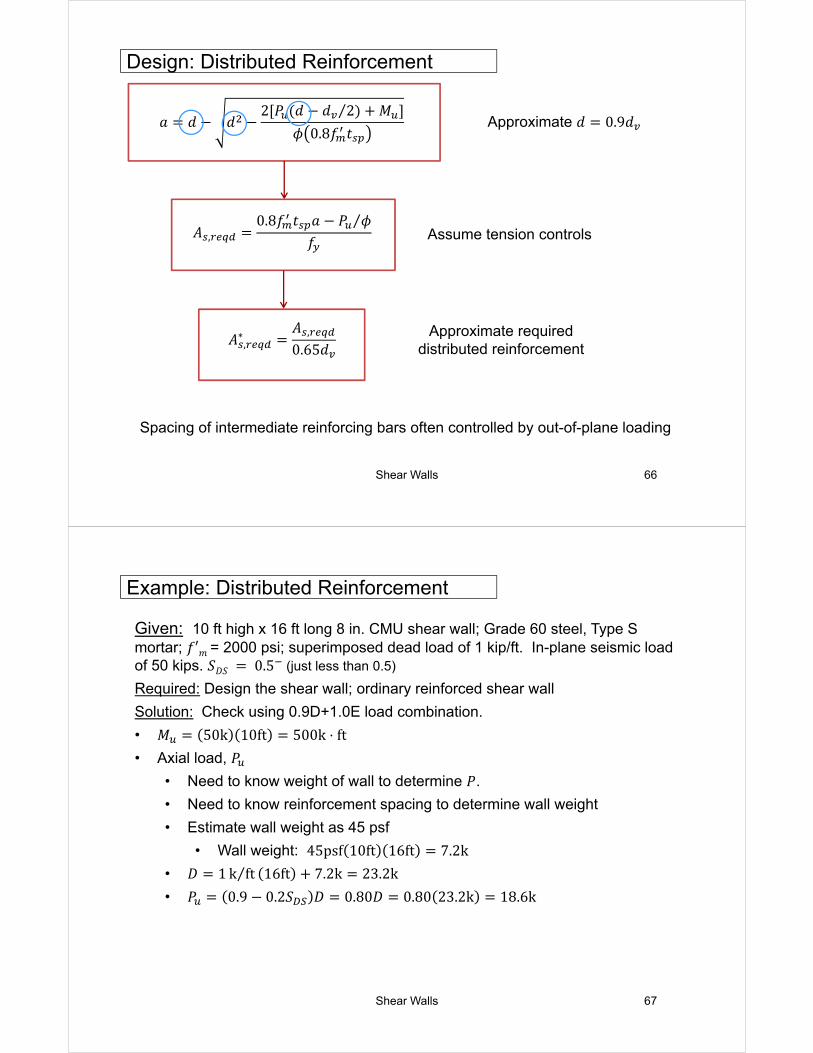
Design: Distributed Reinforcement
Assume tension controls
𝑎 𝑑 𝑑2 𝑃 𝑑 𝑑 2 𝑀⁄
𝜙 0.8𝑓 𝑡
𝐴 ,0.8𝑓 𝑡 𝑎 𝑃 𝜙⁄
𝑓
𝐴 ,∗ 𝐴 ,
0.65𝑑Approximate required
distributed reinforcement
Approximate 𝑑 0.9𝑑
Spacing of intermediate reinforcing bars often controlled by out-of-plane loading
Shear Walls 67
Example: Distributed Reinforcement
Given: 10 ft high x 16 ft long 8 in. CMU shear wall; Grade 60 steel, Type S mortar; 𝑓′𝑚 = 2000 psi; superimposed dead load of 1 kip/ft. In-plane seismic load of 50 kips. 𝑆𝐷𝑆 0.5 (just less than 0.5)
Required: Design the shear wall; ordinary reinforced shear wall
Solution: Check using 0.9D+1.0E load combination.
• 𝑀 50k 10ft 500k ⋅ ft
• Axial load, 𝑃
• Need to know weight of wall to determine 𝑃.
• Need to know reinforcement spacing to determine wall weight
• Estimate wall weight as 45 psf
• Wall weight: 45psf 10ft 16ft 7.2k
• 𝐷 1 k ft⁄ 16ft 7.2k 23.2k
• 𝑃 0.9 0.2𝑆 𝐷 0.80𝐷 0.80 23.2k 18.6k
Shear Walls 68
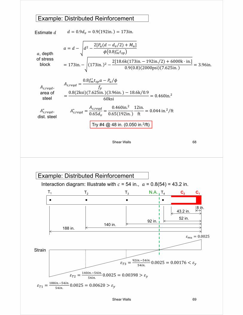
Example: Distributed Reinforcement
𝐴 ,0.8𝑓 𝑡 𝑎 𝑃 𝜙⁄
𝑓0.8 2ksi 7.625in. 3.96in. 18.6k 0.9⁄
60ksi0.460in.
𝑎, depth of stress
block
𝐴 , , area of steel
Estimate 𝑑 𝑑 0.9𝑑 0.9 192in. 173in.
𝐴 ,∗ ,
dist. steel𝐴 ,
∗ 𝐴 ,
0.65𝑑0.460in.
0.65 192in.12in.
ft0.044 in. ft⁄
Try #4 @ 48 in. (0.050 in.2/ft)
𝑎 𝑑 𝑑2 𝑃 𝑑 𝑑 2 𝑀⁄
𝜙 0.8𝑓 𝑡
173in. 173in.2 18.6k 173in. 192in. 2 6000k ⋅ in.⁄
0.9 0.8 2000psi 7.625in.3.96in.
Shear Walls 69
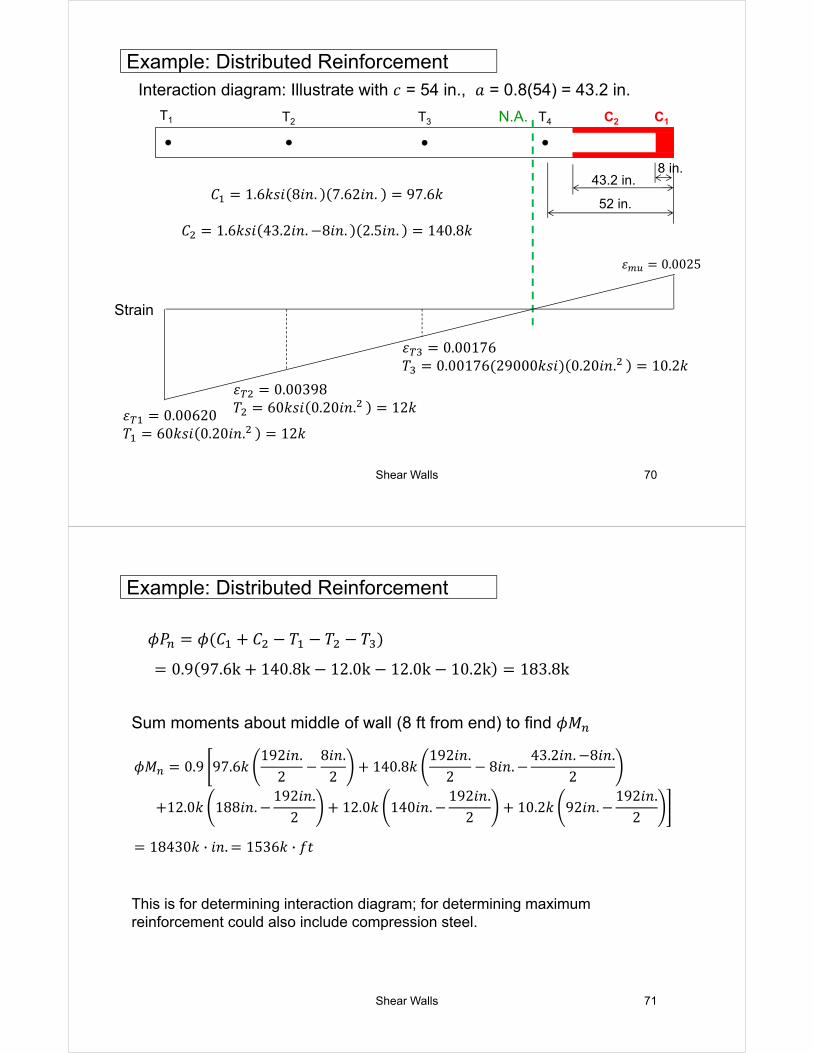
Example: Distributed ReinforcementInteraction diagram: Illustrate with 𝑐 = 54 in., 𝑎 = 0.8(54) = 43.2 in.
8 in.43.2 in.
52 in.92 in.
140 in.
T1 T2 T3 T4 C1C2N.A.
Strain
188 in.
𝜀 0.0025
𝜀. .
.0.0025 0.00620 𝜀
𝜀. .
.0.0025 0.00398 𝜀
𝜀. .
.0.0025 0.00176 𝜀
Shear Walls 70
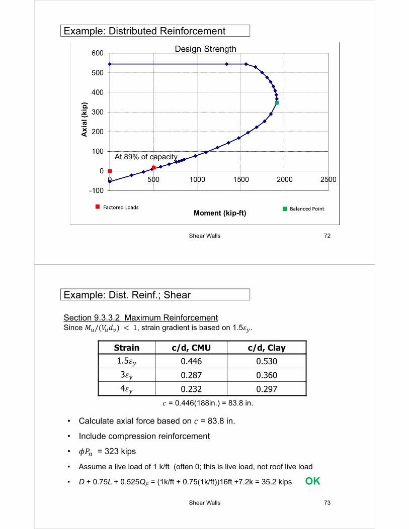
Example: Distributed ReinforcementInteraction diagram: Illustrate with 𝑐 = 54 in., 𝑎 = 0.8(54) = 43.2 in.
8 in.43.2 in.
52 in.
T1 T2 T3 T4 C1C2N.A.
Strain
𝜀 0.0025
𝜀 0.00620𝑇 60𝑘𝑠𝑖 0.20𝑖𝑛. 12𝑘
𝜀 0.00398𝑇 60𝑘𝑠𝑖 0.20𝑖𝑛. 12𝑘
𝜀 0.00176𝑇 0.00176 29000𝑘𝑠𝑖 0.20𝑖𝑛. 10.2𝑘
𝐶 1.6𝑘𝑠𝑖 8𝑖𝑛. 7.62𝑖𝑛. 97.6𝑘
𝐶 1.6𝑘𝑠𝑖 43.2𝑖𝑛. 8𝑖𝑛. 2.5𝑖𝑛. 140.8𝑘
Shear Walls 71
Sum moments about middle of wall (8 ft from end) to find 𝜙𝑀
This is for determining interaction diagram; for determining maximum reinforcement could also include compression steel.
Example: Distributed Reinforcement
𝜙𝑃 𝜙 𝐶 𝐶 𝑇 𝑇 𝑇
0.9 97.6k 140.8k 12.0k 12.0k 10.2k 183.8k
𝜙𝑀 0.9 97.6𝑘192𝑖𝑛.
28𝑖𝑛.
2140.8𝑘
192𝑖𝑛.2
8𝑖𝑛.43.2𝑖𝑛. 8𝑖𝑛.
2
12.0𝑘 188𝑖𝑛.192𝑖𝑛.
212.0𝑘 140𝑖𝑛.
192𝑖𝑛.2
10.2𝑘 92𝑖𝑛.192𝑖𝑛.
2
18430𝑘 · 𝑖𝑛. 1536𝑘 · 𝑓𝑡
Shear Walls 72
Example: Distributed Reinforcement
At 89% of capacity
Shear Walls 73
Example: Dist. Reinf.; Shear
• Calculate axial force based on 𝑐 = 83.8 in.
• Include compression reinforcement
• 𝜙𝑃 = 323 kips
• Assume a live load of 1 k/ft (often 0; this is live load, not roof live load
• D + 0.75L + 0.525QE = (1k/ft + 0.75(1k/ft))16ft +7.2k = 35.2 kips
Section 9.3.3.2 Maximum ReinforcementSince 𝑀 / 𝑉 𝑑 1, strain gradient is based on 1.5𝜀 .
OK
𝑐 = 0.446(188in.) = 83.8 in.
Strain c/d, CMU c/d, Clay
1.5𝜀 0.446 0.530
3𝜀 0.287 0.360
4𝜀 0.232 0.297
Shear Walls 74
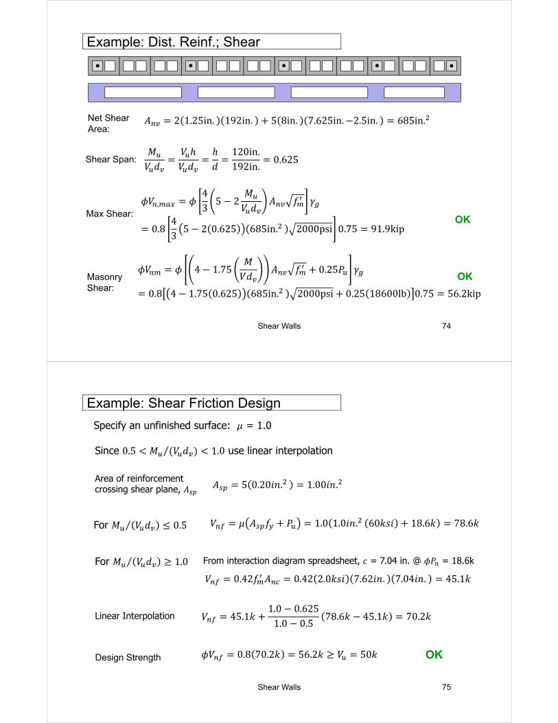
Example: Dist. Reinf.; Shear
𝐴 2 1.25in. 192in. 5 8in. 7.625in. 2.5in. 685in.
OK
𝑀𝑉 𝑑
𝑉 ℎ𝑉 𝑑
ℎ𝑑
120in.192in.
0.625Shear Span:
Max Shear:𝜙𝑉 , 𝜙
43
5 2𝑀
𝑉 𝑑𝐴 𝑓 𝛾
0.843
5 2 0.625 685in. 2000psi 0.75 91.9kip
Masonry Shear:
𝜙𝑉 𝜙 4 1.75𝑀
𝑉𝑑𝐴 𝑓 0.25𝑃 𝛾
0.8 4 1.75 0.625 685in. 2000psi 0.25 18600lb 0.75 56.2kip
OK
Net Shear Area:
Shear Walls 75
Example: Shear Friction Design
Since 0.5 𝑀 𝑉 𝑑⁄ 1.0 use linear interpolation
For 𝑀 𝑉 𝑑 0.5⁄
Specify an unfinished surface: 𝜇 = 1.0
Area of reinforcement crossing shear plane, 𝐴
For 𝑀 𝑉 𝑑 1.0⁄ From interaction diagram spreadsheet, 𝑐 = 7.04 in. @ 𝜙𝑃 = 18.6k
Linear Interpolation
Design Strength OK
𝐴 5 0.20𝑖𝑛. 1.00𝑖𝑛.
𝑉 𝜇 𝐴 𝑓 𝑃 1.0 1.0𝑖𝑛. 60𝑘𝑠𝑖 18.6𝑘 78.6𝑘
𝑉 0.42𝑓 𝐴 0.42 2.0𝑘𝑠𝑖 7.62𝑖𝑛. 7.04𝑖𝑛. 45.1𝑘
𝑉 45.1𝑘1.0 0.625
1.0 0.578.6𝑘 45.1𝑘 70.2𝑘
𝜙𝑉 0.8 70.2𝑘 56.2𝑘 𝑉 50𝑘
Shear Walls 76
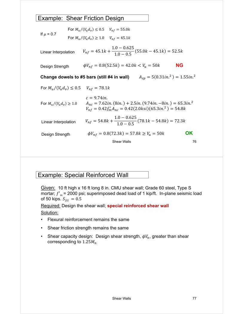
Example: Shear Friction Design
If 𝜇 = 0.7For 𝑀 𝑉 𝑑 0.5⁄ 𝑉 55.0𝑘
For 𝑀 𝑉 𝑑 1.0⁄
Linear Interpolation
Design Strength NG
𝑉 45.1𝑘1.0 0.625
1.0 0.555.0𝑘 45.1𝑘 52.5𝑘
𝜙𝑉 0.8 52.5𝑘 42.0𝑘 𝑉 50𝑘
Change dowels to #5 bars (still #4 in wall) 𝐴 5 0.31𝑖𝑛. 1.55𝑖𝑛.
For 𝑀 𝑉 𝑑 0.5⁄ 𝑉 78.1𝑘
𝑐 9.74𝑖𝑛.𝐴 7.62𝑖𝑛. 8𝑖𝑛. 2.5𝑖𝑛. 9.74𝑖𝑛. 8𝑖𝑛. 65.3𝑖𝑛.𝑉 0.42𝑓 𝐴 0.42 2.0𝑘𝑠𝑖 65.3𝑖𝑛. 54.8𝑘
For 𝑀 𝑉 𝑑 1.0 𝑉 45.1𝑘⁄
Linear Interpolation 𝑉 54.8𝑘1.0 0.625
1.0 0.578.1𝑘 54.8𝑘 72.3𝑘
Design Strength OK𝜙𝑉 0.8 72.3𝑘 57.8𝑘 𝑉 50𝑘
Shear Walls 77
Example: Special Reinforced Wall
Given: 10 ft high x 16 ft long 8 in. CMU shear wall; Grade 60 steel, Type S mortar; 𝑓′𝑚 = 2000 psi; superimposed dead load of 1 kip/ft. In-plane seismic load of 50 kips. 𝑆𝐷𝑆 0.5
Required: Design the shear wall; special reinforced shear wall
Solution:
• Flexural reinforcement remains the same
• Shear friction strength remains the same
• Shear capacity design: Design shear strength, 𝜙𝑉 , greater than shear corresponding to 1.25𝑀
Shear Walls 78
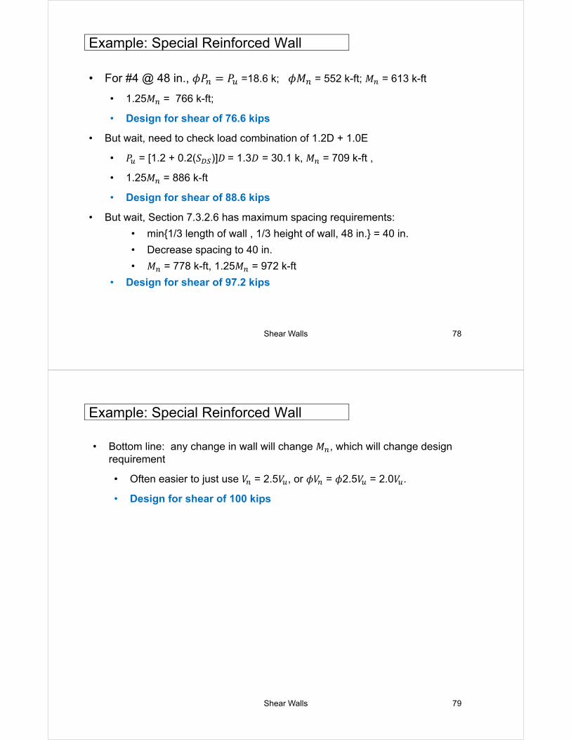
Example: Special Reinforced Wall
• For #4 @ 48 in., 𝜙𝑃 𝑃 =18.6 k; 𝜙𝑀 = 552 k-ft; 𝑀 = 613 k-ft
• 1.25𝑀 = 766 k-ft;
• Design for shear of 76.6 kips
• But wait, need to check load combination of 1.2D + 1.0E
• 𝑃 = [1.2 + 0.2(𝑆 )]𝐷 = 1.3𝐷 = 30.1 k, 𝑀 = 709 k-ft ,
• 1.25𝑀 = 886 k-ft
• Design for shear of 88.6 kips
• But wait, Section 7.3.2.6 has maximum spacing requirements:
• min{1/3 length of wall , 1/3 height of wall, 48 in.} = 40 in.
• Decrease spacing to 40 in.
• 𝑀 = 778 k-ft, 1.25𝑀 = 972 k-ft
• Design for shear of 97.2 kips
Shear Walls 79
Example: Special Reinforced Wall
• Bottom line: any change in wall will change 𝑀 , which will change design requirement
• Often easier to just use 𝑉 = 2.5𝑉 , or 𝜙𝑉 = 𝜙2.5𝑉 = 2.0𝑉 .
• Design for shear of 100 kips
Shear Walls 80
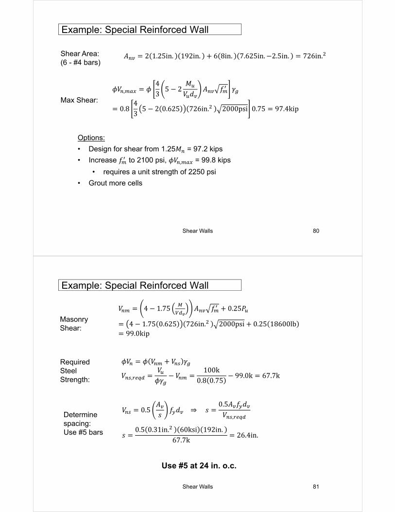
Example: Special Reinforced Wall
Shear Area:(6 - #4 bars)
𝐴 2 1.25in. 192in. 6 8in. 7.625in. 2.5in. 726in.
Max Shear:
𝜙𝑉 , 𝜙43
5 2𝑀
𝑉 𝑑𝐴 𝑓 𝛾
0.843
5 2 0.625 726in. 2000psi 0.75 97.4kip
Options:
• Design for shear from 1.25𝑀 = 97.2 kips
• Increase 𝑓 to 2100 psi, 𝜙𝑉 , = 99.8 kips
• requires a unit strength of 2250 psi
• Grout more cells
Shear Walls 81
Example: Special Reinforced Wall
Masonry Shear:
𝑉 4 1.75 𝐴 𝑓 0.25𝑃
4 1.75 0.625 726in. 2000psi 0.25 18600lb99.0kip
RequiredSteel Strength:
𝜙𝑉 𝜙 𝑉 𝑉 𝛾
𝑉 ,𝑉
𝜙𝛾𝑉
100k0.8 0.75
99.0k 67.7k
Determinespacing:Use #5 bars
𝑉 0.5𝐴𝑠
𝑓 𝑑 ⇒ 𝑠0.5𝐴 𝑓 𝑑
𝑉 ,
𝑠0.5 0.31in. 60ksi 192in.
67.7k26.4in.
Use #5 at 24 in. o.c.
Shear Walls 82
Example: Special Reinforced Wall
Shear Area: 𝐴 7.62in. 192in. 1464in.
Max Shear:𝜙𝑉 , 𝜙
43
5 2𝑀
𝑉 𝑑𝐴 𝑓 𝛾
0.843
5 2 0.625 1464in. 2000psi 1.0 261.9kip
Since horizontal bars are closely spaced, consider fully grouting wall
Masonry Shear:
𝑉 4 1.75 𝐴 𝑓 0.25𝑃
4 1.75 0.625 1464in. 2000psi 0.25 23200lb196.1kip
Wall weight:81psf 10ft 16ft 12.96k𝐷 1 k ft⁄ 16ft 12.96k 28.96k𝑃 0.80𝐷 0.80 28.96k 23.2k
Design Shear:
𝜙𝑉 𝜙 𝛾𝑉 0.8 1.0 196.1𝑘 156.9𝑘 𝑉 100𝑘 OK
Shear Walls 83
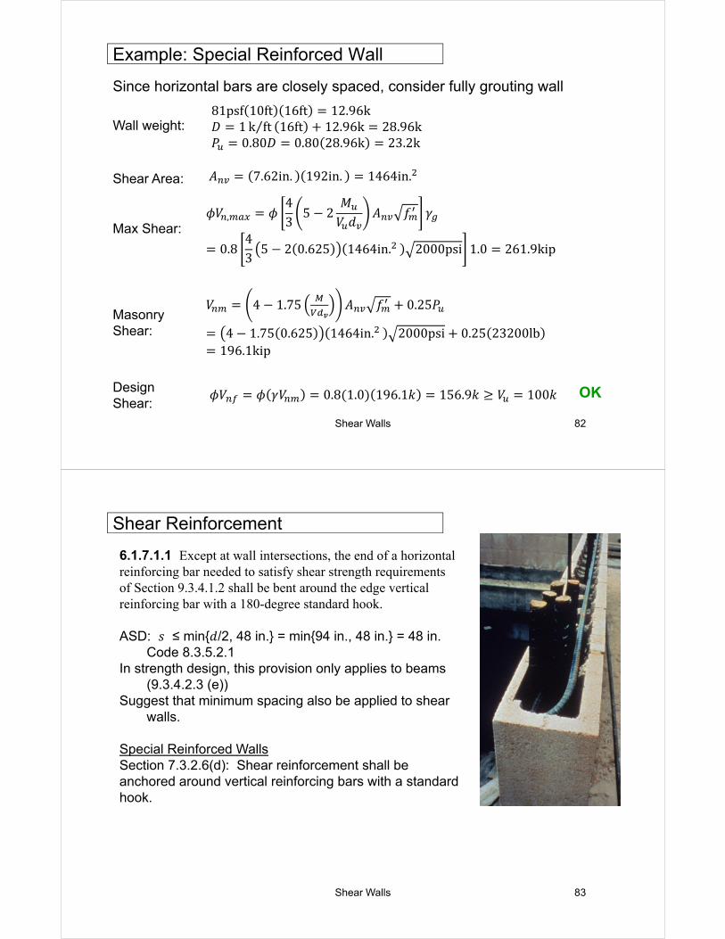
Shear Reinforcement
6.1.7.1.1 Except at wall intersections, the end of a horizontal reinforcing bar needed to satisfy shear strength requirements of Section 9.3.4.1.2 shall be bent around the edge vertical reinforcing bar with a 180-degree standard hook.
ASD: 𝑠 ≤ min{𝑑/2, 48 in.} = min{94 in., 48 in.} = 48 in. Code 8.3.5.2.1
In strength design, this provision only applies to beams (9.3.4.2.3 (e))
Suggest that minimum spacing also be applied to shear walls.
Special Reinforced WallsSection 7.3.2.6(d): Shear reinforcement shall be anchored around vertical reinforcing bars with a standard hook.
Shear Walls 84
• Prescriptive Reinforcement Requirements (7.3.2.6)
• 0.0007 in each direction
• 0.002 total
• Vertical: 6(0.20in.2)/1464in.2 = 0.00082 > 0.0007 OK
• Horizontal: 5(0.31in.2)/[120in.(7.625in.)] = 0.00169 > 0.0007 OK
• Total = 0.00082 + 0.00169 = 0.00251 > 0.002 OK
• Note: for fully grouted wall, would need #5 @ 32in. = 0.00127
Example: Special Wall
Shear Walls 85
• Calculate axial force based on 𝑐 = 83.8 in.
• Include compression reinforcement
• 𝜙𝑃 = 297.8 kips
• For 4𝜀 , 𝜙𝑃 = 160.4 kips
• Live load = 1 kip/ft; wall weight = 12 kip
• D + 0.75L + 0.525QE = 16k + 12k + 0.75(16k) = 40 kips
Section 9.3.3.5 Maximum ReinforcementSince 𝑀 𝑉 𝑑⁄ < 1, strain gradient is based on 1.5𝜀 .
OK
𝑐 = 0.446(188in.) = 83.8 in.
Strain c/d, CMU c/d, Clay
1.5𝜀 0.446 0.530
3𝜀 0.287 0.360
4𝜀 0.232 0.297
Example: Special Wall
Shear Walls 86
• Section 9.3.6.5: Maximum reinforcement provisions of 9.3.3.5 do not apply if designed by this section (boundary elements)
• Special boundary elements not required if:
OK
𝑃 0.1𝑓 𝐴 geometrically symmetrical sections𝑃 0.05𝑓 𝐴 geometrically unsymmetrical sections
AND
For our wall, 𝑀 𝑉 𝑑⁄ < 1
𝑃 0.1𝑓 𝐴 0.1 2.0𝑘𝑠𝑖 1464𝑖𝑛. 293 𝑘
Example: Special Wall
1 OR 𝑉 3𝐴 𝑓 AND 3
Shear Walls 87
• Prescriptive Reinforcement Requirements (7.3.2.6)
• 0.0007 in each direction
• 0.002 total
• Spacing Requirements (7.3.2.6)
• Shear Capacity Design (Section 7.3.2.6.1.1)
• 𝜙𝑉 shear corresponding to 1.25𝑀 .
• 𝑉 need not exceed 2.5𝑉
• Maximum Reinforcement Requirements (9.3.3.5; 9.3.6.5)
Special Wall: Summary
Shear Walls 88
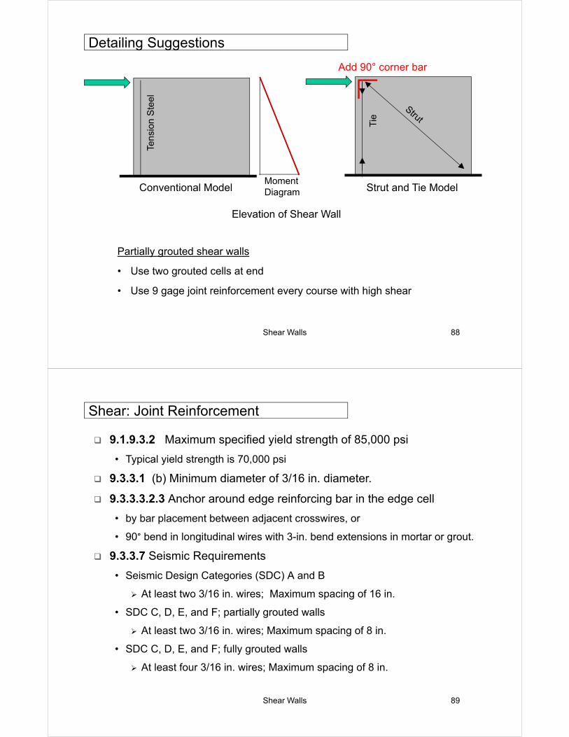
Elevation of Shear Wall
Tie
Add 90° corner bar
Strut and Tie ModelConventional Model
Tens
ion
Ste
el
Moment Diagram
Detailing Suggestions
Partially grouted shear walls
• Use two grouted cells at end
• Use 9 gage joint reinforcement every course with high shear
Shear Walls 89
9.1.9.3.2 Maximum specified yield strength of 85,000 psi
• Typical yield strength is 70,000 psi
9.3.3.1 (b) Minimum diameter of 3/16 in. diameter.
9.3.3.3.2.3 Anchor around edge reinforcing bar in the edge cell
• by bar placement between adjacent crosswires, or
• 90° bend in longitudinal wires with 3-in. bend extensions in mortar or grout.
9.3.3.7 Seismic Requirements
• Seismic Design Categories (SDC) A and B
At least two 3/16 in. wires; Maximum spacing of 16 in.
• SDC C, D, E, and F; partially grouted walls
At least two 3/16 in. wires; Maximum spacing of 8 in.
• SDC C, D, E, and F; fully grouted walls
At least four 3/16 in. wires; Maximum spacing of 8 in.
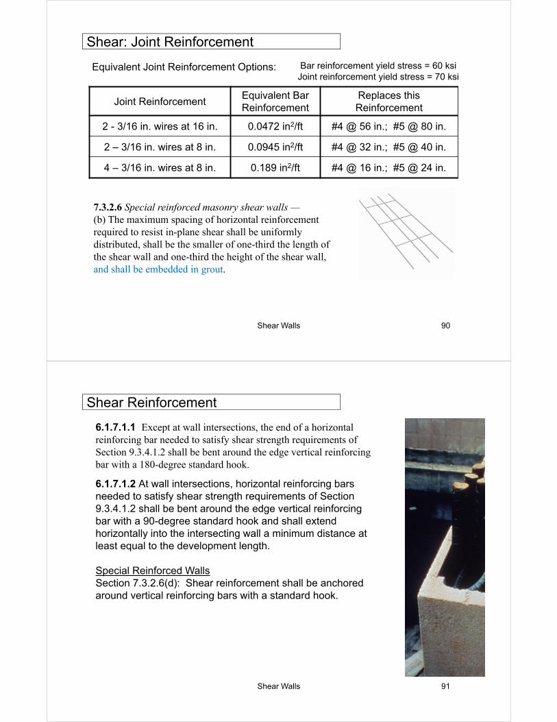
Shear: Joint Reinforcement
Shear Walls 90
Equivalent Joint Reinforcement Options:
Joint ReinforcementEquivalent Bar Reinforcement
Replaces this Reinforcement
2 - 3/16 in. wires at 16 in. 0.0472 in2/ft #4 @ 56 in.; #5 @ 80 in.
2 – 3/16 in. wires at 8 in. 0.0945 in2/ft #4 @ 32 in.; #5 @ 40 in.
4 – 3/16 in. wires at 8 in. 0.189 in2/ft #4 @ 16 in.; #5 @ 24 in.
Bar reinforcement yield stress = 60 ksiJoint reinforcement yield stress = 70 ksi
Shear: Joint Reinforcement
7.3.2.6 Special reinforced masonry shear walls —(b) The maximum spacing of horizontal reinforcement required to resist in-plane shear shall be uniformly distributed, shall be the smaller of one-third the length of the shear wall and one-third the height of the shear wall, and shall be embedded in grout.
Shear Walls 91
Shear Reinforcement
6.1.7.1.1 Except at wall intersections, the end of a horizontal reinforcing bar needed to satisfy shear strength requirements of Section 9.3.4.1.2 shall be bent around the edge vertical reinforcing bar with a 180-degree standard hook.
6.1.7.1.2 At wall intersections, horizontal reinforcing bars needed to satisfy shear strength requirements of Section 9.3.4.1.2 shall be bent around the edge vertical reinforcing bar with a 90-degree standard hook and shall extend horizontally into the intersecting wall a minimum distance at least equal to the development length.
Special Reinforced WallsSection 7.3.2.6(d): Shear reinforcement shall be anchored around vertical reinforcing bars with a standard hook.
Shear Walls 92
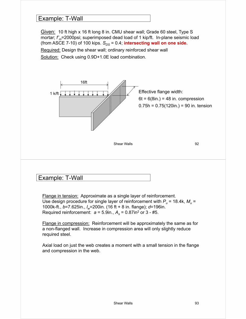
Given: 10 ft high x 16 ft long 8 in. CMU shear wall; Grade 60 steel, Type S mortar; f’m=2000psi; superimposed dead load of 1 kip/ft. In-plane seismic load (from ASCE 7-10) of 100 kips. SDS = 0.4; intersecting wall on one side.
Required: Design the shear wall; ordinary reinforced shear wall
Solution: Check using 0.9D+1.0E load combination.
1 k/ft
16ft
Effective flange width:
6t = 6(8in.) = 48 in. compression
0.75h = 0.75(120in.) = 90 in. tension
Example: T-Wall
Shear Walls 93
Flange in tension: Approximate as a single layer of reinforcement.Use design procedure for single layer of reinforcement with Pu = 18.4k, Mu = 1000k-ft., b=7.625in., lw=200in. (16 ft + 8 in. flange); d=196in. Required reinforcement: a = 5.9in., As = 0.87in2 or 3 - #5.
Flange in compression: Reinforcement will be approximately the same as for a non-flanged wall. Increase in compression area will only slightly reduce required steel.
Axial load on just the web creates a moment with a small tension in the flange and compression in the web.
Example: T-Wall
Shear Walls 94
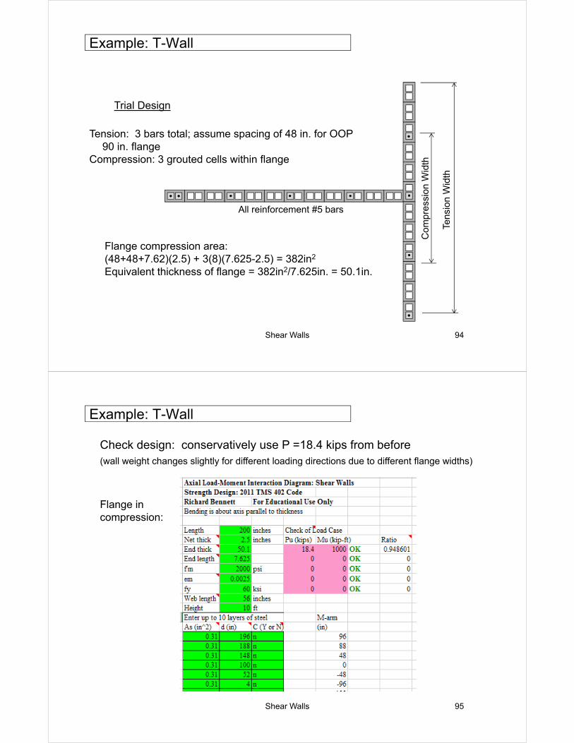
Trial Design
Tension: 3 bars total; assume spacing of 48 in. for OOP90 in. flange
Compression: 3 grouted cells within flange
Flange compression area:(48+48+7.62)(2.5) + 3(8)(7.625-2.5) = 382in2
Equivalent thickness of flange = 382in2/7.625in. = 50.1in.
Com
pres
sion
Wid
th
Tens
ion
Wid
th
All reinforcement #5 bars
Example: T-Wall
Shear Walls 95
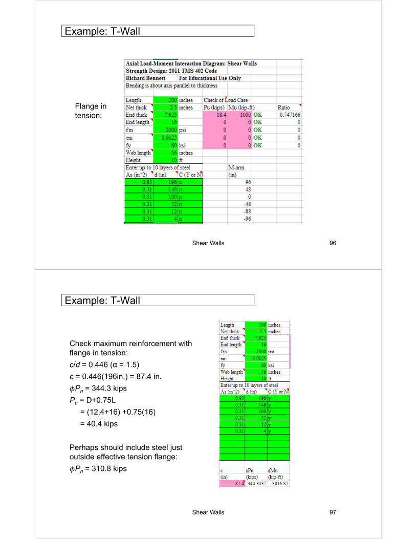
Check design: conservatively use P =18.4 kips from before(wall weight changes slightly for different loading directions due to different flange widths)
Flange in compression:
Example: T-Wall
Shear Walls 96
Flange in tension:
Example: T-Wall
Shear Walls 97
Check maximum reinforcement with flange in tension:
c/d = 0.446 (α = 1.5)
c = 0.446(196in.) = 87.4 in.
𝜙Pn = 344.3 kips
Pu = D+0.75L
= (12.4+16) +0.75(16)
= 40.4 kips
Perhaps should include steel just outside effective tension flange:
𝜙Pn = 310.8 kips
Example: T-Wall
Shear Walls 98
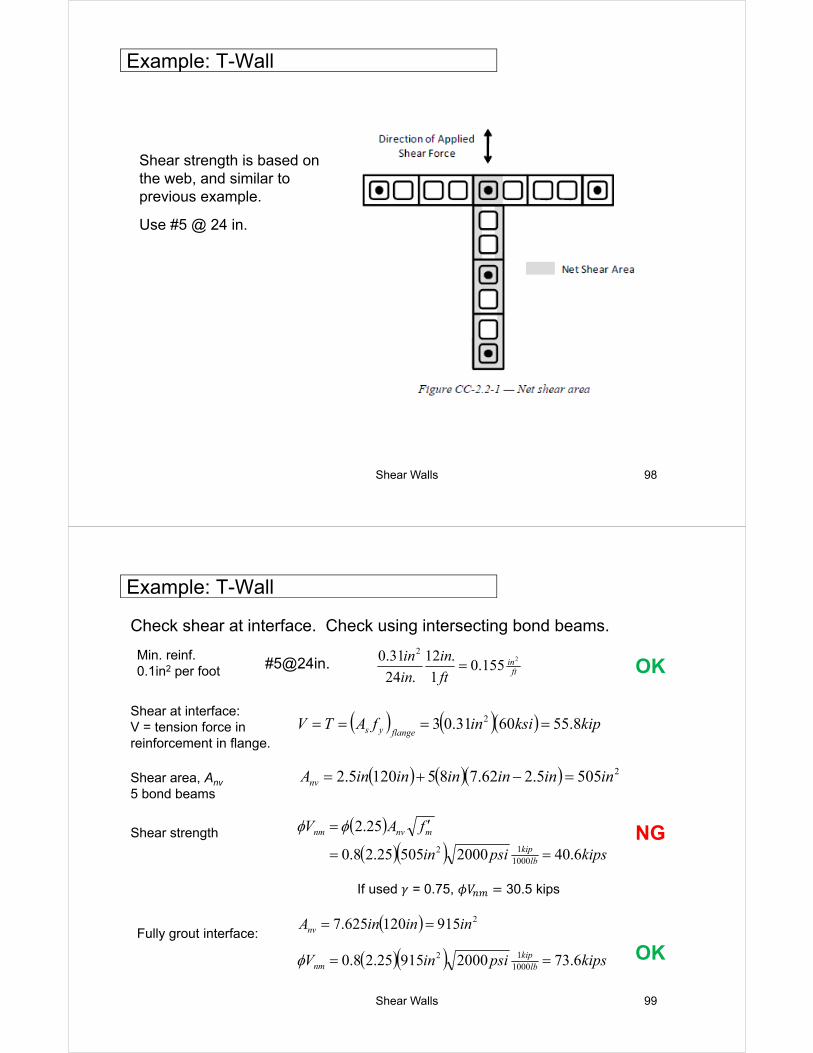
Shear strength is based on the web, and similar to previous example.
Use #5 @ 24 in.
Example: T-Wall
Shear Walls 99
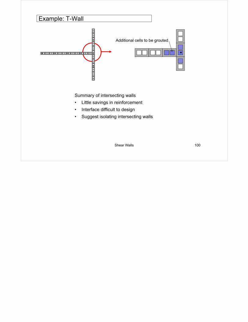
Check shear at interface. Check using intersecting bond beams.
in
ft
in
in
in 2
155.01
.12
.24
31.0 2
Shear at interface: V = tension force in reinforcement in flange.
25055.262.7851205.2 ininininininAnv
kipspsiin
fAV
lbkip
mnvnm
6.40200050525.28.0
25.2
100012
If used 𝛾 = 0.75, 𝜙𝑉 30.5 kips
Example: T-Wall
Min. reinf.0.1in2 per foot OK
kipksiinfATVflangeys 8.556031.03 2
Shear area, Anv
5 bond beams
Shear strength NG
Fully grout interface: 2915120625.7 inininAnv
kipspsiinV lbkip
nm 6.73200091525.28.0 100012 OK
Shear Walls 100
Additional cells to be grouted
Summary of intersecting walls
• Little savings in reinforcement
• Interface difficult to design
• Suggest isolating intersecting walls
Example: T-Wall


![SHEAR WALLS FOR HIGH RISE BUILDINGS [].ppt](https://img.pdfslide.us/doc/110x75/55cf8531550346484b8bb1be/shear-walls-for-high-rise-buildings-wwwebmfilescomppt.jpg)