Embed Size (px)
Citation preview
Shear Strengthening of RC Beams with Near-Surface-Mounted CFRP Laminates
Salvador Dias and Joaquim Barros
Synopsis: The efficacies of the Near Surface Mounted (NSM) and Externally Bonded Reinforcing (EBR) techniques for the shear strengthening of rectangular cross section RC beams are compared. Both techniques are based on the use of carbon fiber reinforced polymer (CFRP) materials. The NSM was the most effective technique, and was also the easiest and fastest to apply, and assured the lowest fragile failure modes. The performance of the ACI and fib analytical formulations for the EBR shear strengthening was appraised. In general, the contribution of the CFRP systems predicted by the analytical formulations was larger than the values registered experimentally. The capability of the De Lorenzis formulation of predicting the contribution of the NSM technique for the shear strengthening of RC beams was appraised using bond stress and CFRP effective strain values obtained in pullout bending tests. This formulation provided values 61% lower than the values obtained experimentally. Keywords: Carbon fiber reinforced polymers, Externally bonded reinforcing, Near surface mounted, Shear strengthening
Salvador Dias is a PhD Student at the Department of Civil Engineering of Minho University, Portugal. In 2001 he concluded his MSc from the Faculty of Engineering of Porto University, Portugal. His research interests include the application of fiber-reinforced polymer materials for the structural strengthening and rehabilitation. ACI member Joaquim Barros is Professor of the Structural Division of Minho University, Portugal. He received his BS, MSc and PhD from Faculty of Civil Engineering of Porto University, Portugal. He is a member of ACI Committees 440 (Fiber reinforced polymers), 506 (Shotcrete) and 544 (Fiber reinforced concrete). His research interests include structural strengthening, composite materials, fiber reinforced concrete and finite element method.
INTRODUCTION The use of fiber reinforced polymer (FRP) materials for structural repair and strengthening has continuously increased in the last years, due to several advantages resulting from opting for these composites in detriment of traditional construction materials such as steel, wood and concrete. These benefits include low weight, easy installation, high durability (non corrosive) and tensile strength, electromagnetic neutrality and practically unlimited availability in size, geometry and dimension [1, 2, 3]. Externally bonded reinforcing (EBR) technique using FRP laminates and wet lay-up sheets has been used to increase the shear resistance of RC beams [4]. The analysis of research studies confirmed that the shear resistance of RC beams can be significantly increased from applying the EBR technique. The carried out research has, however, revealed that this technique cannot mobilize the full tensile strength of FRP materials, due to their premature debonding. Furthermore, EBR reinforcements could be highly susceptible to damage from collision, fire and temperature variation, ultraviolet rays, and moisture absorption [5]. In an attempt at overcoming these drawbacks, a strengthening technique designated by near surface mounted (NSM) was proposed, where FRP rods are fixed into pre-cut grooves opened on the concrete cover of the elements to be strengthened [6]. Barros and Dias [7] proposed a similar strengthening technique based on installing CFRP laminate strips into pre-cut slits opened on the concrete cover. The CFRP was bonded to concrete by epoxy adhesive. This strengthening technique has already been used to increase the load carrying capacity of concrete structures failing in bending [8, 9, 10]. The obtained results showed that this technique is more efficient and easy to apply than EBR technique. This higher effectiveness is derived from the larger CFRP laminate-concrete bond stress values that can be mobilized in the NSM technique [11]. To assess the efficacy of the NSM technique for increasing the shear resistance of RC beams, an experimental program of four-point bending tests was carried out. Influences of the longitudinal tensile steel reinforcement, slρ , laminate strip inclination and beam depth on the efficacy of the NSM technique were analyzed. This efficacy was assessed not only in terms of the increase of maximum load and deflection at beam rupture, but also in terms of the beam strengthening performance per unit length of the applied

material. The performance of the analytical formulations proposed by ACI [1], fib [2] and De Lorenzis [6] for the shear strengthening was appraised.
RESEARCH SIGNIFICANCE The efficacies of the NSM and EBR techniques for the shear strengthening of rectangular cross section RC beams are compared in terms of the increase of maximum load, the deflection at beam rupture and the failure mode. For the NSM technique, the beam strengthening performance per unit length of the applied material is assessed. The performance of the ACI and fib analytical formulations for the shear strengthening with externally bonded wet lay-up FRP systems is appraised. The capability of the De Lorenzis formulation of predicting the contribution of the NSM technique for the shear strengthening of RC beams is checked.
EXPERIMENTAL PROGRAM The experimental program is composed of the four test series represented in Fig. 1. Each series is made up of a beam without any shear reinforcement (R) and a beam for each of the following shear reinforcing systems: steel stirrups of φ6 mm (S), U shaped strips of wet lay-up CFRP sheet (M) and CFRP laminate strips at 45º (IL) or at 90º (VL) in relation to the beam axis. The M beams were strengthened by EBR technique, while in IL and VL beams laminate strips of CFRP were installed into pre-cut slits opened on the concrete cover of the beam’s lateral surfaces (NSM technique), see Fig. 2. Series A10 and A12 are composed of beams with a cross section of 0.15x0.30 m2 and a span length of 1.5 m. Series B10 and B12 are constituted of beams with a cross section of 0.15x0.15 m2 and a span length of 0.9 m. To evaluate the influence of slρ , series A10 and B10 had 4φ10 steel bars at bottom surface, while A12 and B12 series had 4φ12. The shear span, a, (Fig. 1) in both series of beams was two times the depth of the corresponding beams. At top surface, the beams of all series were reinforced with 2φ6 steel bars. The concrete clear cover for the top, bottom and lateral faces of the beams was 15 mm. Table 1 includes general information of the beams composing the four series. Further information can be found elsewhere [7]. The amount of shear reinforcement applied on the four reinforcing systems was evaluated in order to assure that all beams would fail in shear, at a similar load carrying capacity. The percentage of the CFRP shear reinforcing systems was evaluated to provide a contribution for the beam shear resistance similar to the one of the steel stirrups. For the strips of wet lay-up CFRP sheets of U shape, the recommendations of the ACI Committee 440 were followed [1]. For the NSM CFRP laminate strips, the formulation used for the steel stirrups was adopted, but the yield stress was replaced by an effective stress that was determined assuming a CFRP strain value of 4‰, that is the maximum effective strain value recommended by ACI Committee 440 for the EBR shear reinforcing systems. Steel stirrups were not applied in the series reinforced with CFRP systems. The authors are aware that this scenario would probably never be encountered in practical situations since a certain percentage of steel stirrups always exist in reinforced concrete elements, even if it is inadequate. However, since the main purpose of the present research is to assess the
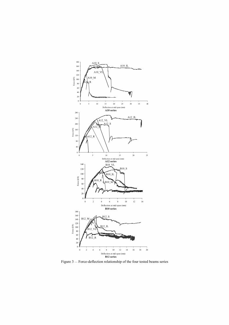
effectiveness of NSM shear strengthening technique, the interaction between the CFRP shear reinforcement and the steel stirrups will be only investigated in future experimental programs. Tables 2 and 3 include the main properties of the concrete and steel bars used in the experimental program, respectively. The average values of the concrete compression strength at 28 days and at the date of testing the beams were evaluated from uniaxial compression tests with cylinders of 150 mm diameter and 300 mm height. The properties of the steel bars were obtained from uniaxial tensile tests. Two CFRP systems were used on the present work: unidirectional wet lay-up sheets of 25 mm width and precured laminates of 1.4×10 mm2 cross-section. These CFRP systems have the properties indicated in Table 4. The relationship between the force and the deflection at mid span of the tested beams is represented in Figure 3. Table 5 includes the main results obtained in the four tested beam series. Adopting the designation of Fmax,K_R and Fmax,K_S for referring the maximum load of a beam without shear reinforcement and a beam reinforced with steel stirrups, respectively, (K represents the beam series) the ratios Fmax/Fmax,K_R and Fmax/Fmax,K_S were determined for assessing the efficacy of the shear strengthening techniques, in terms of increasing the beam load carrying capacity. From the results obtained in the experimental program, the following main conclusions can be pointed out: • The CFRP shear strengthening systems applied in the present work increased
significantly the shear resistance of concrete beams; • The NSM shear strengthening technique was the most effective of the CFRP systems.
This effectiveness was not only in terms of the beam load carrying capacity, but also in terms of the deformation capacity at beam’s failure. Using the load carrying capacity of the unreinforced beams for comparison purposes, the beams strengthened by EBR and NSM techniques showed an average increase of 54% and 83%, respectively;
• Increasing the beam depth, laminates at 45º became more effective than vertical laminates;
• Fmax of the beams reinforced with steel stirrups and Fmax of the beams strengthened by NSM technique were almost similar;
• Failure modes of the beams strengthened by the NSM technique were not so fragile as the ones observed in the beams strengthened by the EBR technique.
APPRAISAL THE PERFORMANCE OF ANALYTICAL FORMULATIONS
Taking the results obtained in the tested beams strengthened with EBR technique, the performance of the analytical formulations proposed by ACI [1] and fib [2] was appraised. The documents published by these institutions are not yet dealing with the NSM technique. Thereby, the applicability of the analytical formulation proposed by De Lorenzis [6] was checked, using for this purpose the experimental results obtained in the beams strengthened with NSM laminate strips. Since De Lorenzis's formulation was developed for FRP reinforcing rod elements, the necessary adjustments were introduced
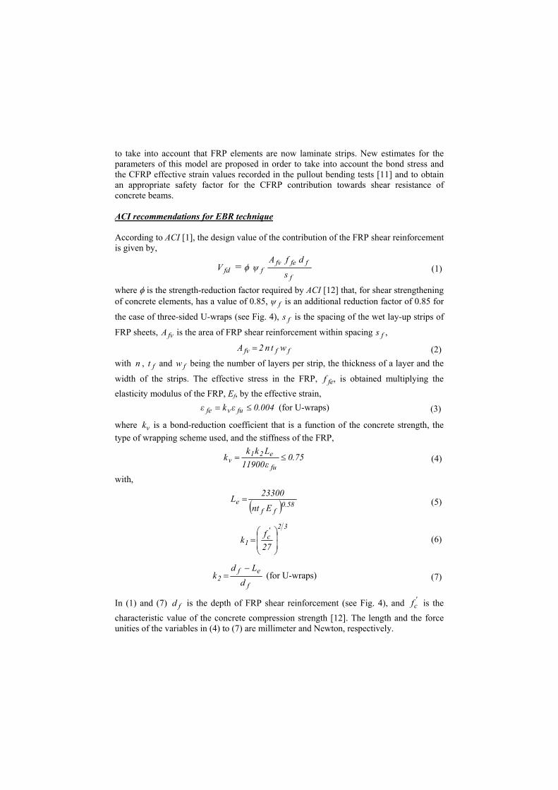
to take into account that FRP elements are now laminate strips. New estimates for the parameters of this model are proposed in order to take into account the bond stress and the CFRP effective strain values recorded in the pullout bending tests [11] and to obtain an appropriate safety factor for the CFRP contribution towards shear resistance of concrete beams. ACI recommendations for EBR technique According to ACI [1], the design value of the contribution of the FRP shear reinforcement is given by,
fdV = φ f
ffefvf s
dfAψ (1)
where φ is the strength-reduction factor required by ACI [12] that, for shear strengthening of concrete elements, has a value of 0.85, fψ is an additional reduction factor of 0.85 for
the case of three-sided U-wraps (see Fig. 4), fs is the spacing of the wet lay-up strips of
FRP sheets, fvA is the area of FRP shear reinforcement within spacing fs ,
fffv wtn2A = (2) with n , ft and fw being the number of layers per strip, the thickness of a layer and the
width of the strips. The effective stress in the FRP, fef , is obtained multiplying the elasticity modulus of the FRP, Ef, by the effective strain,
004.0εkε fuvfe ≤= (for U-wraps) (3)
where νk is a bond-reduction coefficient that is a function of the concrete strength, the type of wrapping scheme used, and the stiffness of the FRP,
75.0ε11900Lkk
kfu
e21v ≤= (4)
with,
( ) 58.0ff
eEnt
23300L = (5)
32'c
1 27f
k
= (6)
f
ef2 d
Ldk
−= (for U-wraps) (7)
In (1) and (7) fd is the depth of FRP shear reinforcement (see Fig. 4), and 'cf is the
characteristic value of the concrete compression strength [12]. The length and the force unities of the variables in (4) to (7) are millimeter and Newton, respectively.

In Table 6, the values obtained with this formulation are compared to those registered experimentally. Apart beam B10_M, the ACI formulation has estimated a FRP contribution for the shear strengthening that was larger than the contribution recorded experimentally. A deficient bond of the strip crossed by the shear failure crack might have caused the high abnormal value of .exp
f.ana
fd VV of A10_M beam, since this strip
has debonded prematurely (see Fig. 5). Fib recommendations for EBR technique
According to fib recommendations [2], the contribution of wet lay-up strips of FRP sheets for shear strengthening is evaluated by the following expression,
dbρEε9.0V wffd,fefd = (8) where wb and d are the width of the beam cross section and the distance from extreme compression fiber to the centroid of the nonprestressed steel tension reinforcement. In (8)
fρ is the FRP shear reinforcement ratio,
fw
fvf sb
Aρ = (9)
and d,feε is the design effective strain in the FRP, that can be obtained from feε , 0.300.56
2 3 2 33min 0.65 10 ; 0.17cm cm
fe fuf f f f
f fE E
ε ερ ρ
− = ×
( cmf in MPa and fE in GPa) (10)
applying two safety factors, d,feε = 0.8 feε /1.3, the first one, 0.8, to convert feε in a characteristic value and the second one, 1.3, that depends on the FRP failure mode (debonding in the present case). In (10) cmf is the cylinder average concrete compression
strength and fuε is the ultimate FRP strain. The analytical and the experimental results are compared in Table 7. Apart beam B12_M, fib formulation has also predicted an FRP contribution larger than the experimentally registered values. Like in the ACI formulation, an abnormal high .exp
f.ana
fd VV value was also obtained in A10_M beam,
which stresses the suspicious that the strip crossing the shear failure crack was deficiently bonded. Fig. 6 compares the values of the CFRP contribution for the shear strengthening according to ACI and fib formulations. In general, all the formulations have estimated large values than the ones registered experimentally. Apart B12_M beam, in the remaining beams the ACI formulation estimated lower values than fib. The differences between the values from ACI and fib are, however, not too significant. De Lorenzis analytical formulation for NSM technique
According to De Lorenzis [6], the contribution of the NSM FRP elements for shear strengthening is the minimum value of f1V and f2V ,
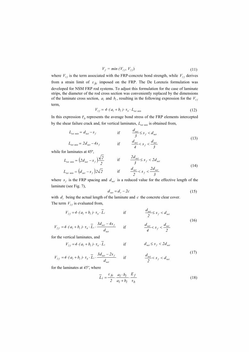
fV = min ( f1V , f2V ) (11) where f1V is the term associated with the FRP-concrete bond strength, while f2V derives from a strain limit of feε imposed on the FRP. The De Lorenzis formulation was developed for NSM FRP rod systems. To adjust this formulation for the case of laminate strips, the diameter of the rod cross section was conveniently replaced by the dimensions of the laminate cross section, la and lb , resulting in the following expression for the f1V term,
mintotbllf1 Lτ)ba(4V ⋅⋅+⋅= (12)
In this expression bτ represents the average bond stress of the FRP elements intercepted by the shear failure crack and, for vertical laminates, mintotL is obtained from,
fnetmintot sdL −= if netfnet ds3
d<≤
fnetmintot s4d2L −= if 3
ds
4d net
fnet <<
(13)
while for laminates at 45º,
( )22sd2L fnetmintot −= if netf
net d2s3
d2<≤
( ) 22sdL fnetmintot −= if 3
d2s
2d net
fnet <<
(14)
where fs is the FRP spacing and netd is a reduced value for the effective length of the laminate (see Fig. 7),
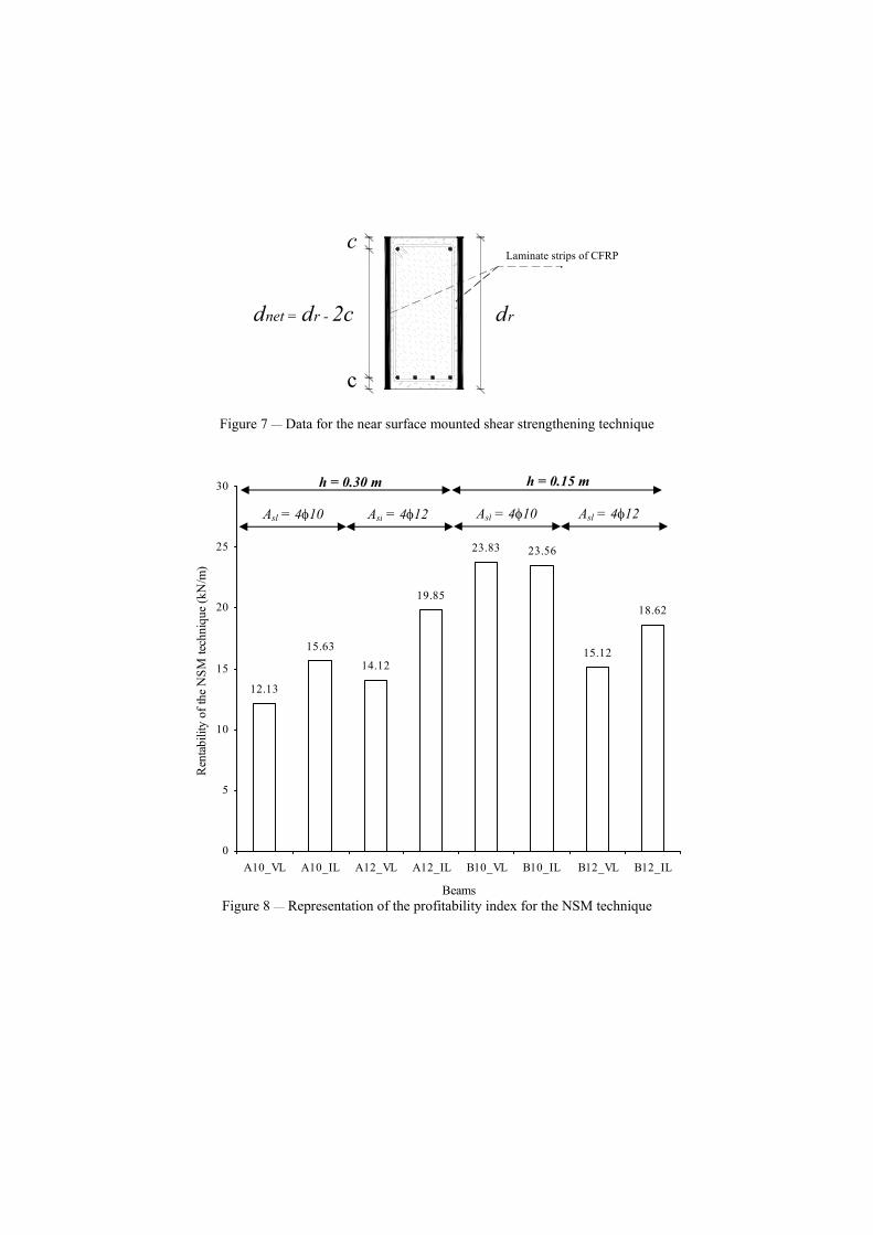
c2dd rnet −= (15) with rd being the actual length of the laminate and c the concrete clear cover. The term f2V is evaluated from,
ibllf2 Lτ)ba(4V ⋅⋅+⋅= if netfnet ds2
d<≤
net
fnetibllf2 d
s4d3Lτ)ba(4V
−⋅⋅⋅+⋅= if
2ds
4d net
fnet <<
(16)
for the vertical laminates, and
ibllf2 Lτ)ba(4V ⋅⋅+⋅= if netfnet d2sd <≤
net
fnetibllf2 d
s2d3Lτ)ba(4V
−⋅⋅⋅+⋅= if netf
net ds2
d<<
(17)
for the laminates at 45º, where
b
f
ll
llfei
τE
baba
2ε
L ⋅+⋅
⋅= (18)
According to De Lorenzis [6], if
inet L2d < (19) in the case of vertical laminates, or if
inet L2d < (20)
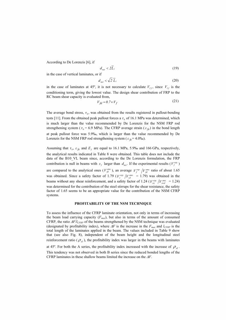
in the case of laminates at 45º, it is not necessary to calculate f2V , since f1V is the conditioning term, giving the lowest value. The design shear contribution of FRP to the RC beam shear capacity is evaluated from,
ffd V7.0V ×= (21)
The average bond stress, bτ , was obtained from the results registered in pullout-bending tests [11]. From the obtained peak pullout forces a bτ of 16.1 MPa was determined, which is much larger than the value recommended by De Lorenzis for the NSM FRP rod strengthening system ( bτ = 6.9 MPa). The CFRP average strain ( feε ) in the bond length at peak pullout force was 5.9‰, which is larger than the value recommended by De Lorenzis for the NSM FRP rod strengthening system ( feε = 4.0‰). Assuming that bτ , feε and fE are equal to 16.1 MPa, 5.9‰ and 166 GPa, respectively, the analytical results indicated in Table 8 were obtained. This table does not include the data of the B10_VL beam since, according to the De Lorenzis formulation, the FRP contribution is null in beams with fs larger than netd . If the experimental results ( .exp
fV )
are compared to the analytical ones ( .anafdV ), an average .ana
fd.exp
f VV ratio of about 1.65 was obtained. Since a safety factor of 1.79 ( .ana
cd.exp
c VV = 1.79) was obtained in the beams without any shear reinforcement, and a safety factor of 1.24 ( .ana
swd.exp
sw VV = 1.24) was determined for the contribution of the steel stirrups for the shear resistance, the safety factor of 1.65 seems to be an appropriate value for the contribution of the NSM CFRP systems.
PROFITABILITY OF THE NSM TECHNIQUE To assess the influence of the CFRP laminate orientation, not only in terms of increasing the beam load carrying capacity (Fmax), but also in terms of the amount of consumed CFRP, the ratio ∆F/lCFRP of the beams strengthened by the NSM technique was evaluated (designated by profitability index), where ∆F is the increase in the Fmax and lCFRP is the total length of the laminates applied in the beam. The values included in Table 9 show that (see also Fig. 8), independent of the beam height and the longitudinal steel reinforcement ratio ( slρ ), the profitability index was larger in the beams with laminates
at 45º. For both the A series, the profitability index increased with the increase of slρ . This tendency was not observed in both B series since the reduced bonded lengths of the CFRP laminates in these shallow beams limited the increase on the ∆F.
CONCLUSIONS The main purpose of the present research is to assess the effectiveness of the near surface mounted (NSM) technique for the shear strengthening of RC beams. In comparison to the performance of the experimentally bonded reinforcing (EBR) technique, the NSM was the more effective technique, and was also easier and faster to apply, and assured lower fragile failure modes. Using the ACI and fib formulations for the evaluation of the contribution of the CFRP EBR strengthening systems for the beam shear resistance, it was verified that these formulations have given design values 2% and 8% higher than the values registered experimentally, respectively, (a beam with a deficient bonding was not considered in this analysis). Using similar EBR shear strengthening configuration, other researchers have obtained larger safety factors. However, these researchers have used wet lay-up CFRP sheets of Young’s modulus (Ef) of about 220 GPa, and, in the major cases, the shear CFRP strips were formed of one layer. In the present research a CFRP sheet of Ef=390 GPa and strips of two layers were used. This indicates that the expressions of ACI and fib formulations defining the FRP effective strain were not well calibrated for this situation, since they are providing too high effective strain values when using stiffer shear CFRP systems. Therefore, more research is needed in this field. Assuming a bond stress of 16.1 MPa and an effective strain of 5.9‰ (average values of the data recorded in pullout bending tests), the De Lorenzis formulation predicted a CFRP contribution around 61% of the experimentally registered values, which seems to provide an appropriate safety factor (1.65).
ACKNOWLEDGEMENTS The authors of the present work wish to acknowledge the materials provided by the degussa Portugal, S&P and Unibetão (Braga). The study reported in this paper forms a part of the research program “CUTINSHEAR - Performance assessment of an innovative structural FRP strengthening technique using an integrated system based on optical fiber sensors” supported by FCT, POCTI/ECM/59033/2004.
REFERENCES
[1] ACI Committee 440, 2002, “Guide for the design and construction of externally bonded FRP systems for strengthening concrete structures”, American Concrete Institute, 118 pp. [2] CEB-FIP Model Code, 1993, Comite Euro-International du Beton, Bulletin d’Information nº 213/214. [3] Bakis, C.E., Bank, L.C., Brown, V.L., Cosenza, E., Davalos, J.F., Lesko, J.J., Machida, A., Riskalla, S.H. and Triantafillou, T.C., 2002, “Fiber-Reinforced Polymer Composites for Construction – State-of-the-art Review”, Journal of Composites for Construction, Vol. 6, Nº2, May, pp. 73-87.
[4] Bousselham A. and Chaallal, O., 2004, “Shear Strengthening Reinforced Concrete Beams with Fiber-Reinforced Polymer: Assessment of Influencing Parameters and Required Research”, ACI Structural Journal, Vol. 101, Nº 2, March-April, pp. 219-227. [5] ACI Committee 440, 1996, “State of the art report on fiber reinforced plastic reinforcement for concrete structures” (Reapproved 2002), ACI Committee 440, 68 pp. [6] De Lorenzis, Laura, 2002, “Strengthening of RC Structures with Near-Surface Mounted FRP rods”, PhD Thesis in Civil Engineering, Universita’ Degli Studi di Lecce, Italy, May, 289 pp. [7] Barros, J.A.O. and Dias, S.J.E., 2003, “Shear strengthening of reinforced concrete beams with laminate strips of CFRP”, Proceedings of the International Conference Composites in Constructions - CCC2003, Italia, September, pp. 289-294. [8] Blaschko, M. and Zilch, K., 1999, “Rehabilitation of concrete structures with CFRP strips glued into slits”, Proceedings of the Twelfth International Conference of Composite Materials, ICCM 12, Paris, France (CD-ROM). [9] El-Hacha, R. and Riskalla S.H., 2004, “Near-Surface-Mounted Fiber-Reinforced Polymer Reinforcements for Flexural Strengthening of Concrete Structures”, ACI Structural Journal, Vol. 101, Nº5, September-October, pp. 717-726. [10] Barros, J.A.O., Sena-Cruz, J.M., Dias, S.J.E., Ferreira, D.R.S.M. and Fortes, A. S., 2004, “Near surface mounted CFRP-based technique for the strengthening of concrete structures”, Workshop on R+D+I in Technology of Concrete Structures - tribute to Dr. Ravindra Gettu, Barcelona, Spain, October, pp. 205-217 (CD-ROM). [11] Sena-Cruz, J.M. and Barros, J.A.O., 2004, “Bond between near-surface mounted CFRP laminate strips and concrete in structural strengthening”, Journal of Composites for Construction, Vol. 8, Nº 6, pp. 519-527. [12] ACI Committee 318, 2002, “Building code requirements for structural concrete and commentary”, American Concrete Institute, Reported by ACI Committee 118.
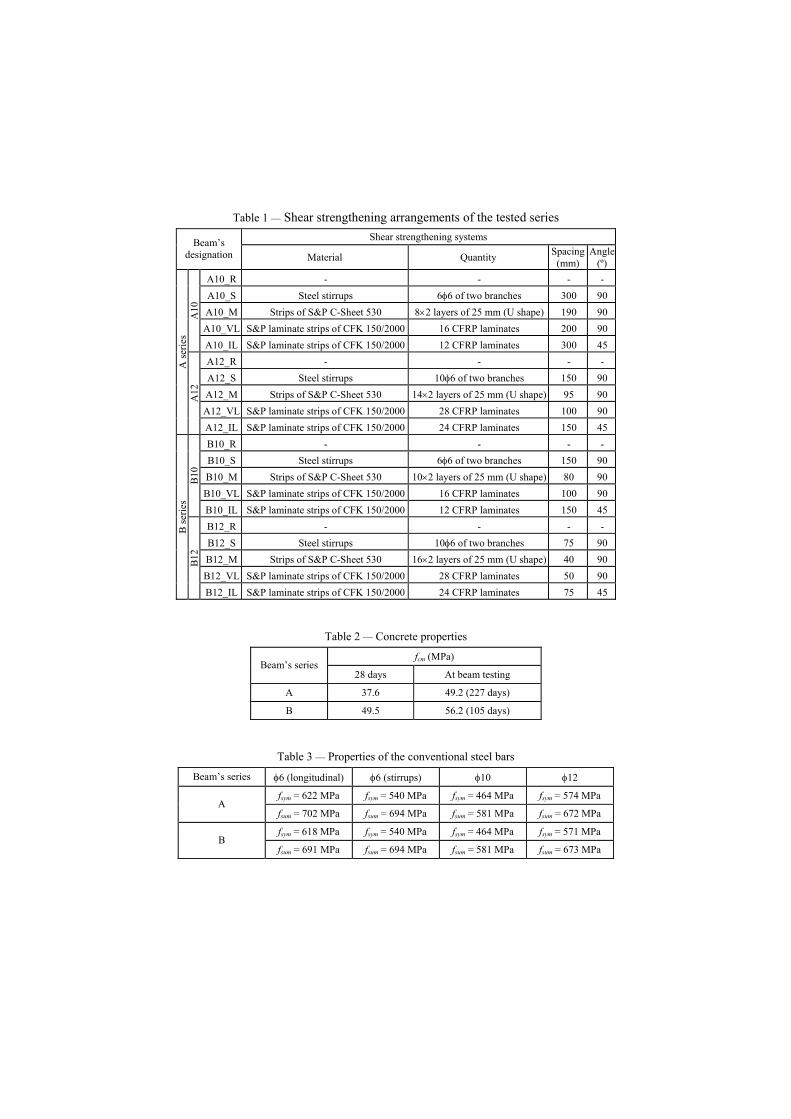
Table 1 — Shear strengthening arrangements of the tested series Shear strengthening systems Beam’s
designation Material Quantity Spacing (mm)
Angle (º)
A10_R - - - - A10_S Steel stirrups 6φ6 of two branches 300 90 A10_M Strips of S&P C-Sheet 530 8×2 layers of 25 mm (U shape) 190 90 A10_VL S&P laminate strips of CFK 150/2000 16 CFRP laminates 200 90
A10
A10_IL S&P laminate strips of CFK 150/2000 12 CFRP laminates 300 45 A12_R - - - - A12_S Steel stirrups 10φ6 of two branches 150 90 A12_M Strips of S&P C-Sheet 530 14×2 layers of 25 mm (U shape) 95 90 A12_VL S&P laminate strips of CFK 150/2000 28 CFRP laminates 100 90
A se
ries
A12
A12_IL S&P laminate strips of CFK 150/2000 24 CFRP laminates 150 45 B10_R - - - - B10_S Steel stirrups 6φ6 of two branches 150 90 B10_M Strips of S&P C-Sheet 530 10×2 layers of 25 mm (U shape) 80 90 B10_VL S&P laminate strips of CFK 150/2000 16 CFRP laminates 100 90
B10
B10_IL S&P laminate strips of CFK 150/2000 12 CFRP laminates 150 45 B12_R - - - - B12_S Steel stirrups 10φ6 of two branches 75 90 B12_M Strips of S&P C-Sheet 530 16×2 layers of 25 mm (U shape) 40 90 B12_VL S&P laminate strips of CFK 150/2000 28 CFRP laminates 50 90
B se
ries
B12
B12_IL S&P laminate strips of CFK 150/2000 24 CFRP laminates 75 45
Table 2 — Concrete properties
fcm (MPa) Beam’s series
28 days At beam testing
A 37.6 49.2 (227 days)
B 49.5 56.2 (105 days)
Table 3 — Properties of the conventional steel bars
Beam’s series φ6 (longitudinal) φ6 (stirrups) φ10 φ12
fsym = 622 MPa fsym = 540 MPa fsym = 464 MPa fsym = 574 MPa A
fsum = 702 MPa fsum = 694 MPa fsum = 581 MPa fsum = 672 MPa
fsym = 618 MPa fsym = 540 MPa fsym = 464 MPa fsym = 571 MPa B
fsum = 691 MPa fsum = 694 MPa fsum = 581 MPa fsum = 673 MPa
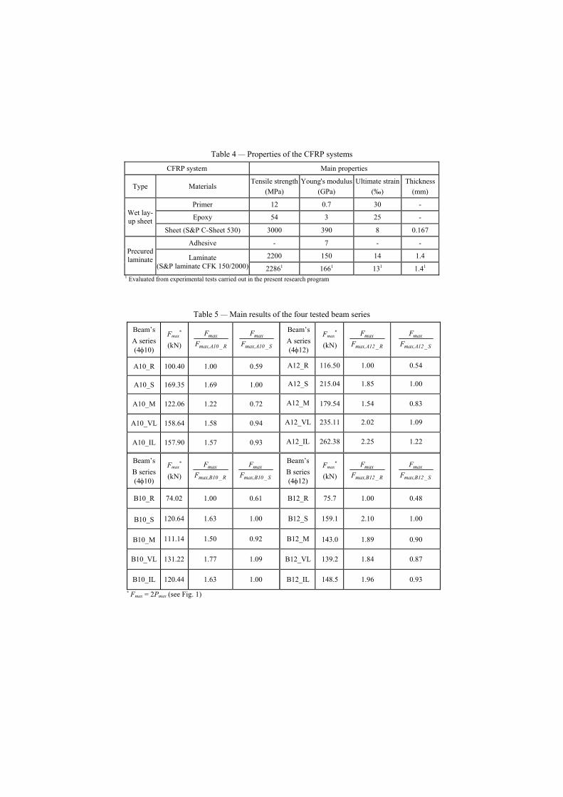
Table 4 — Properties of the CFRP systems
CFRP system Main properties
Type Materials Tensile strength
(MPa) Young's modulus
(GPa) Ultimate strain
(‰) Thickness
(mm)
Primer 12 0.7 30 -
Epoxy 54 3 25 - Wet lay-up sheet
Sheet (S&P C-Sheet 530) 3000 390 8 0.167
Adhesive - 7 - -
2200 150 14 1.4 Precured laminate Laminate
(S&P laminate CFK 150/2000) 22861 1661 131 1.41 1 Evaluated from experimental tests carried out in the present research program
Table 5 — Main results of the four tested beam series
* Fmax = 2Pmax (see Fig. 1)
Beam’s A series (4φ10)
Fmax*
(kN) R_10Amax,
maxF
F S_10Amax,
maxF
F Beam’s A series (4φ12)
Fmax*
(kN) R_12Amax,
maxF
F
S_12Amax,
maxF
F
A10_R 100.40 1.00 0.59 A12_R 116.50 1.00 0.54
A10_S 169.35 1.69 1.00 A12_S 215.04 1.85 1.00
A10_M 122.06 1.22 0.72 A12_M 179.54 1.54 0.83
A10_VL 158.64 1.58 0.94 A12_VL 235.11 2.02 1.09
A10_IL 157.90 1.57 0.93 A12_IL 262.38 2.25 1.22
Beam’s B series (4φ10)
Fmax*
(kN) R_10Bmax,
maxF
F S_10Bmax,
maxF
F Beam’s B series (4φ12)
Fmax*
(kN) R_12Bmax,
maxF
F
S_12Bmax,
maxF
F
B10_R 74.02 1.00 0.61 B12_R 75.7 1.00 0.48
B10_S 120.64 1.63 1.00 B12_S 159.1 2.10 1.00
B10_M 111.14 1.50 0.92 B12_M 143.0 1.89 0.90
B10_VL 131.22 1.77 1.09 B12_VL 139.2 1.84 0.87
B10_IL 120.44 1.63 1.00 B12_IL 148.5 1.96 0.93
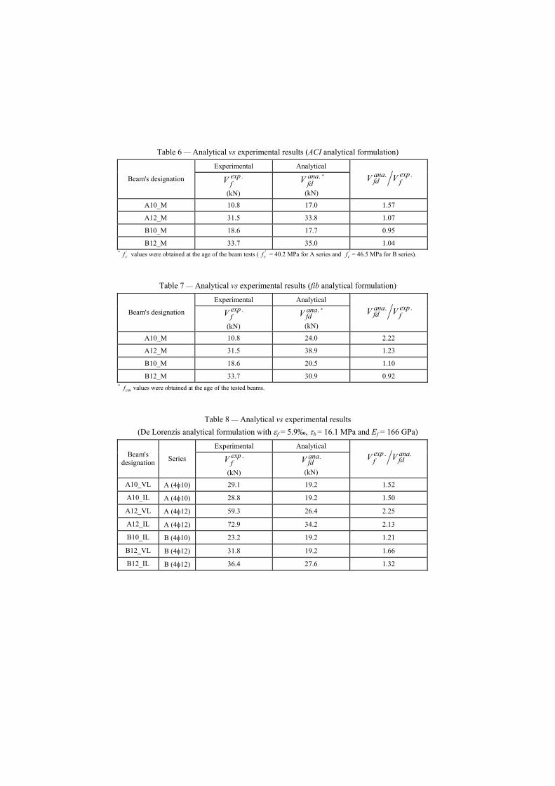
Table 6 — Analytical vs experimental results (ACI analytical formulation)
Experimental Analytical
Beam's designation .expfV
(kN)
.anafdV *
(kN)
.expf
.anafd VV
A10_M 10.8 17.0 1.57
A12_M 31.5 33.8 1.07
B10_M 18.6 17.7 0.95
B12_M 33.7 35.0 1.04 * '
cf values were obtained at the age of the beam tests ( 'cf = 40.2 MPa for A series and '
cf = 46.5 MPa for B series).
Table 7 — Analytical vs experimental results (fib analytical formulation)
Experimental Analytical
Beam's designation .expfV
(kN)
.anafdV *
(kN)
.expf
.anafd VV
A10_M 10.8 24.0 2.22
A12_M 31.5 38.9 1.23
B10_M 18.6 20.5 1.10
B12_M 33.7 30.9 0.92 * cmf values were obtained at the age of the tested beams.
Table 8 — Analytical vs experimental results (De Lorenzis analytical formulation with εf = 5.9‰, τb = 16.1 MPa and Ef = 166 GPa)
Experimental Analytical Beam's
designation Series .expfV
(kN)
.anafdV
(kN)
.anafd
.expf VV
A10_VL A (4φ10) 29.1 19.2 1.52
A10_IL A (4φ10) 28.8 19.2 1.50
A12_VL A (4φ12) 59.3 26.4 2.25
A12_IL A (4φ12) 72.9 34.2 2.13
B10_IL B (4φ10) 23.2 19.2 1.21
B12_VL B (4φ12) 31.8 19.2 1.66
B12_IL B (4φ12) 36.4 27.6 1.32
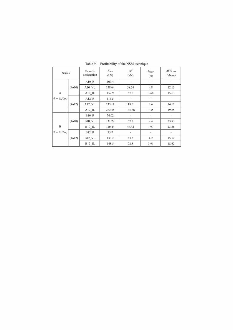
Table 9 — Profitability of the NSM technique
Series Beam’s designation
Fmax
(kN) ∆F
(kN) lCFRP (m)
∆F/lCFRP (kN/m)
A10_R 100.4 - - -
A10_VL 158.64 58.24 4.8 12.13 (4φ10)
A10_IL 157.9 57.5 3.68 15.63
A12_R 116.5 - - -
A12_VL 235.11 118.61 8.4 14.12
A
(h = 0.30m)
(4φ12)
A12_IL 262.38 145.88 7.35 19.85
B10_R 74.02 - - -
B10_VL 131.22 57.2 2.4 23.83 (4φ10)
B10_IL 120.44 46.42 1.97 23.56
B12_R 75.7 - - -
B12_VL 139.2 63.5 4.2 15.12
B
(h = 0.15m)
(4φ12)
B12_IL 148.5 72.8 3.91 18.62

200
300
50
150200200300200200 200 300
300300300
PP
300 190 190190
300150300
190 190 190
P
300
P
PP
1500 50
25PP
1504∅10
300
PPa2∅6
A10_R Cross section
A10_S
A10_VL
A10_M
A10_IL
A10 series
50
150
6x95
6x1006x100 300 150
150150150 300150 150150
P P
150150
80150 15015080 150300
6x95300
PP
P P
1500 50
25P P
1504∅12
P Pa2∅6
A12_R
A12_S
A12_VL
Cross section300
A12_M
A12_IL
A12 series
150
100100 100
150
50
100100 100300 15080150 80 300
8060150150
P
300
P
8080 6080
P
30080 80
P
P
900
P
50
150
4∅10
25P
150
P
Cross section
a PP2∅6
B10_R
B10_S
B10_VL
B10_M
B10_IL
B10 series
4∅12
6x50 300 3x75 406x50 300
P P
4x75 300
P
7x40 3004x75
P P
90050
P
50 150
3x7540
P
7x40
P 25
150
2∅6PPa
Cross sectionB12_R
B12_S
B12_VL
B12_M
B12_IL
B12 series
Figure 1 — Tested series

Externally Bonded Reinforcing (EBR)
An emery is applied to remove the
superficial cement paste
A layer of primer is applied to enhance the adherence of the
concrete substrate
Strips of sheet are glued on the lateral beam’s surfaces using
epoxy resin
Near Surface Mounted (NSM)
Slits are opened on the concrete
cover of the lateral beam’s surface Laminates are introduced into the slits pre-filled with epoxy
adhesive. The epoxy adhesive in excess is removed
Figure 2 — Techniques for the shear strengthening of reinforced concrete beams
0
20
40
60
80
100
120
140
160
180
0 5 10 15 20 25 30 35 40
Deflection at mid span (mm)
Forc
e (k
N)
A10 series
0
40
80
120
160
200
240
280
0 5 10 15 20 25
Deflection at mid span (mm)
Forc
e (k
N)
A12 series
0
20
40
60
80
100
120
140
0 2 4 6 8 10 12 14
Deflection at mid span (mm)
Forc
e (k
N)
B10 series
0
20
40
60
80
100
120
140
160
180
0 2 4 6 8 10 12 14 16 18 20
Deflection at mid span (mm)
Forc
e (k
N)
B12 series
Figure 3 — Force-deflection relationship of the four tested beams series
A10_R A10_M
A10_IL A10_S
A10_VL
A12_S
A12_R
A12_M
A12_IL A12_VL
B10_R B10_M
B10_IL
B10_S B10_VL
B12_R
B12_M
B12_VL B12_IL
B12_S

sfU Strips of wet lay-up
CFRP sheets
df
wf
bw Figure 4 — Data for the externally bonded shear strengthening technique
Figure 5 — Failure of A10_M beam
31.5
18.6
33.7
17.0
33.8
17.7
35.0
24
38.9
20.5
30.9
10.8
0
5
10
15
20
25
30
35
40
45
A10_M A12_M B10_M B12_M
Cont
ribut
ion
of th
e CF
RP (k
N)
Experimental ACI fib
Figure 6 — Analytical vs experimental results (ACI and fib analytical formulation)
Strip prematurely debonded
c
c
dnet = dr - 2c
Laminate strips of CFRP
dr
Figure 7 — Data for the near surface mounted shear strengthening technique
12.13
15.6314.12
19.85
23.83 23.56
15.12
18.62
0
5
10
15
20
25
30
A10_VL A10_IL A12_VL A12_IL B10_VL B10_IL B12_VL B12_IL
Beams
Ren
tabi
lity
of th
e N
SM te
chni
que
(kN
/m)
Figure 8 — Representation of the profitability index for the NSM technique
h = 0.30 m h = 0.15 m
Asl = 4φ10 Asl = 4φ12 Asl = 4φ10 Asl = 4φ12