Embed Size (px)
Citation preview
I
"
Prootroeled Concrote Bridge Member.
ProGreet Report ,17 A
SHEAR STRENGTH OF PRE~
STRESSED CONCRETE BEAMS
byI
,Rene E. WaltherI
L.EHIGH UNIVERSITY
Fritz Laboratory Roport 22S. 17A
Novombor 1987

•
ACKNOWLEDGEMENTS
This work has been carried out at
LEHIGH UNIVERSITYFRITZ ENGINEERING LABORATORY
DEPARTMENT OF CIVIL ENGINEERING
DirectorProfessor W.J. Eney
as a part of an investigation sponsored by
PENNSYLVANIA STATE HIGHWAY DEPARTMENTU.S. BUREAU OF PUBLIC ROADSREINFORCED CONCRETE RESEARCH COUNCILCONCRETE PRODUCTS DIVISION, AMERICAN
MARIETTA COMPANYAMERICAN STEEL AND WIRE DIVISION, U.S.
STEEL CORPORATIONJOHN A. ROEBLING'S SONS CORPORATIONLEHIGH UNIVERSITY
For valuable advice, the author is especiallyindepted to
Professor CARL E. EKBERG, JR.and
Professor BRUNO THURLIMANN
Active assistance in the preparation of this study wasgiven by: Mssrs'. MarioJ ~Danieri, Charles R. Wilson,JoseL. Montemayor, Research Assistants, and'"Mr. AlexW.A:dl~r. The manuscript was typed by Miss MarianneZimmermann.
The author wish~s to express his sincere thankS andappreciation for all'the'help'and advice he enjoyedin the course of this investigation.
TABLE OF CONTENTS
SYNOPSIS
STATEMENT OF THE PROBLEM 1
THEORY OF SHEAR FAILURES FOR CONVENTIONALLYREINFORCED BEAMS WITHOUT WEB AND COMPRESSIONREINFORCEMENT 9
GENERALIZATION FOR PRESTRESSING WEB ANDCOMPRESSION REINFORCEMENT 18
THE INFLUENCE OF THE MAGNITUDE OF THE SHEARFORCE 26
ASSESSEMENT OF PARAMETERS AND COMPARISON WITHTEST RESULTS 30
SUMMARY AND RECOMME~DATION 34
REFERENCES 38
NOTATIONS 40
..
SYNOPSIS
The prediction of the ultimate strength of pre
stressed and conventionally reinforced concrete beams under
the combined action of moment and shear (abbreviately called
"shear strength l1) has previously been based on empirical
formulas. A purely theoretical solution was not realized
because no failure mechanism pertaining to the region of
moment and shear was established.
A theoretical approach is sought herein, by stating
a hypothesis concerning the failure mechanism associated
with the development of diagonal cracks. The deformations
in this region are stipulated to result from a "shear
rotation" about the ~eutral axis of the prospective failure
section, thus furnishing a relationship between the de
formations of steel and concrete at failure. This consti
tutes a substitute for Navier-Bernoulli's hypothesis that
plane cross-sections remain plane after deformation, the
latter being invalid for diagonally cracked sections. The
configuration of the internal forces at failure is then
obtained by observing the equilibrium conditions and the
critical stresses produced by the deformations. The strength
of the concrete compressive zone is determined by comparing
the prevailing state of stress with Mohr's failure criterion
for plain concrete. The deformation of the longitudinal tension
reinforcement is attributed to a pull-aut effect of the steel
relative to the surrounding concrete, thus accounting for the
influence of the bond characteristic of the reinforcement.
The theory is presented for prestressed and conven
tionally reinforced concrete beams, including variations in
cross-section, end restraint, loading, web and compression rein
forcement.
Theoretical estimates are compared with test results.
Reasonable agreement is obtained.
UEBERBLICK
Die rechnungsmaessige Erfassung der Schubfestigkeit
vorgespannter Betonbalken beruhte bisher weitgehend auf
empirischen Formeln. Eine rein theoretische Loesung wurde
hauptsaechlich dadurch verunmoeglicht, dass kein allgemein
gueltiger Verformungsmechanismus fuer die gerissene Schub
zone gefunden werden konnte.
1m Folgenden ist versucht, eine theoretische Loesung
dieses Problems zu finden, indem eine Bruchhypothese fuer
die von Schubrissen durchsetzte Zone aufgestellt wird. Es
wird angenommen, dass ~ie Verformungen im Gebiete der Schub
risse von einer Drehung urn die neutrale Achse des voraus
sichtlichen Bruchschnittes herruehren. Dies stellt einen
Ersatz dar fuer Navier-Bernoulli's Hypothese vom Ebenbleiben
der Querschnitte, die bekanntlich nur im Gebiet der reinen
Biegung gilt. Auf diese Weise wird eine Beziehung zwischen
den Deformationen des Stahles und des Betons bei Erschoepfung
des Schubwiderstandes gewonnen. Die Groesse der Schnittkraefte
im Bruchzustand kann damit aus Gleichgewichtsbedingungen der
den Verformungen entsprechenden Spannungen hergeleitet werden.
Die Bruchbedingung der noch wirksamen Betonzone wird mit Hilfe
von Mohr's Bruchtheorie bestimmt. Die Verformung der Beweh
rung wird einer Relativverschiebung von Stahl und Beton
I .
(Schlupf) zugeschrieben, wodurch der Einfluss der Verbund-
charakteristik erfasst ist.
Die Theorie umfasst Stahl- und Spannbeton unter Be-
ruecksichtigung verschiedener Balkenquerschnitte, Einspan
nungsgrade, Belastungsanordnungen, Schub- und Laengsbeweh
rdngen. Die Ergebnisse dieser Theorie wurden mit Versuchs-
resultaten verglichen. Befriedigende Uebereinstimmung wurde
erzielt.

RESUME
Jusqu!a pr~sent, le calcul de la r~sistance des
poutres en b~ton arm~ ou precontraint sous l!action com-
bin~e du moment et de l!effort tranchant (appele en abrege
"resistance au cisaillement"), etait base sur des formules
. . 1· hI. ! I / / demp~r~ques. Une so ut~on t eor~que n a pas ete trouvee u
faitqu!il n!a pas ete possible d'e~ablir un mecanisme de
rupture pour la zone tranchante.
Cet article essaye d'apporter une solution theorique
a ce probleme, en etablissant une hypothese concerna~t le
mecanisme de rupture associe au developpement de fissures
diagonales. On suppose que les deformations dans cette,
region proviennent d!une rotation en travers autour de l'axe
neutre de la section de rupture ~ventuelle, donnant ainsi
une relation entre les d~formations de l'acier et du beton,
aU.moment de la rupture. Cette hypothese peut remplacer celie
de Navier-Bernoulli qui n'est pas valable pour des sections
~ fissure diagonale et suivant laquelle lessections planes
res tent planes apres deformation. La configuration des ten-
sions internes au moment de la rupture est alors obtenue
en ~tudiant les conditions d'equilibre et les tensions cri-
tiquesproduites par les deformations. La resistance de la
zone en compression du beton est d~terminee en comparant
- .~ ..::
l'etat de tension existant et le critere de rupture de Mohr
pour le btton seul. La deformation de l6armature longitu-
dinale est attribu~e au glissement relatif de l~acier et
/. .du beton environnant, expliquant ainsi l6influence de
l'adh&rence de l6armature.
La theorie est presentee pour des poutres en beton
precontraint et des poutres en b{ton arm~, y compris les
"." hvariations de section, restrainte des extrem1tes, c arges,
armature de compression et d'~triers.
Les valeurs th{oriques sont compare-es aux resultats
des essais. La conformite obtenue est satisfaisante.
SINOPSIS
En formulas emp!ricas ha sido basada hasta hoy 1a
prediccion de 1a resistencia Itmite de vigas de concreto
preesforzado, asi como de las £rmadas con refuerzo ordinari.o
(Hormigon armado)~ sujetas a la accion co~bi.nada de momento
y corte (tambien llamada "resistencia cortante"). El principal
obstacu10 de una solucion teorica pura fue e1 no haberse
estab1ecido un mecanisme de falla referente a la region de
grietas diagonales.
Tratase de encontrar una aproximacion raciona1 a1
problema al establecer una hip6tesis concerniente al mecanisme
de falla asocia.do con el desarrollo de grietas diagorlCilles ~I "" '"
considerando que las deformaciones occurridas en esta region
som. el resultado de una "rotacion cortante" con respecto al eje
neutro de la seccion transversal en la que se espera la falla~
teniendose de esta manera una relacion entre las deformaciones
de acero y concreto al tiempo de falla. Esto constituye un
substituto de la hip6tesis Navier-Bernoulli: secciones planas
.permanecen planas despues de la deformacion,'oo siendo valida
esta ultima debido a la presencia de grietas diagonales o
La configuracion de las fuerzas intern~s ea, entonce~
obtenida observando las condicioRes de equilibrio y los esfuerzos

cr{ticos causados por las deformaciones o La resistencia del
concreto en la zona de compresion es determinada comparando el
estado prevaleciente de esfuerzos con el criterio de falla de
Mohr para concreto simpleo'La deforro~ci6m del refuerzo longi=
tudinal a la tension es atribuida a un desplazamientorelativo
entre acero y concreto 9 explicando esto,la influencia que
tienea las caracteristicas de adherencia del refuerzo.
La teor{a es presentada para vig~s de concreto reforzado
ordinariamente y preesforzado, incluyendo variaciones en seccion-
transversal, condiciones de apoyo, cargas, refuerzo en el alma y a
la compresion o Una razonable armonia se obtiene al comparar
calculos teoricos COR resultados de pruebas experimentales o
I •
STATEMENT OF THE PROBLEM
In spite of extensive research, stretching over more
than half a century, the problem of shear failures has again
and again occupied the interest or even concern of engineers.
This is partly because of changes in design concepts and
partly because of the introduction of new structural materials.
In particular the development of prestressed concrete has
brought new aspects to the proplem, as is clearly recognized
in most current codes. While those for conventionally rein
forced concrete preds>minantly deal with the design of the
web reinforcement to exclude shear failures, it has been deemed
necessary in prestressed concrete to provide also against
a development of diagonal cracks. This is in line with the
modern trend of considering safety against unserviceability (1)
in addition to safety against failure, even though these two
aspects are scarcely distinguished explicitly in thecod~,s..
The provisions for serviceability, i.e. the provisions
against the development of diagonal cracks, are ?sually drafted
as limita~ions of the maximum principal tension stresses, which
may occur either in the web zone or at the extreme tension
fiber of a beam. Such. provisions are certainly adequate, since,
within the accuracy of predictions attainable for concrete

- 2 -
members, the crack development is governed by these principal
stresses. Consequently, the cracks can be assumed to follow
the stress trajectories, which is in accordance with ex=
perimental findings (2). It has to be ernphazised, however,
that such provisions are con£ined 1) to considerations of
serviceability and 2) to the range of elastic or a.t least
quasi elastic behavior of the materials employed. Except
for very special ca$es, they do not permit an estimation of
the ultimate shear strength.
The provision~ against shear failure rest on a less
rational basis. Since no satisfactory theoretical approach
for the prediction of the shear strength has yet bee.n found,
it is usually sought to raise the shear strength above the
flexural bending strength, by providing sufficient web rei.n'"
forcement. Thus, for want of more pertinent information, the
current codes specify that under ultimate load the web rein'
force~ent be designed to resist a tensile force statically
equivalent to the principal tensile stresses which would
exist in the concrete had it remained uncracked. Now, this
procedure involves two obvious shortcomings: firstly the
forces in the web reinforcement after cracking are not sta~
tically equivalent to the principal stresses calculated

- 3 -
assuming an uncracked section and secondly shear failure ~ay
occur no matter how high the percentage of web reinforcement
is chosen. From a theoretical standpoint, it is therefore
unsatisfactory to base the design of the shear reinforcement
on the ultimate load as limited by pure bending. Nevertheless,
such a design provides definitely some safety against shear
failures. The magnitude of the safety margin and the economy
of design remain, however, beyond control.
For all these reasons, it has always been felt desirable
to gain more knowledge about the ultimate load as limited by
shear failure. There exists a number of excellent investiga-
t · . * t f th t' h t t' 11 .~ons, mos 0 em per a~n owever 0 conven ~ona y re~n-
forced concrete, whereas information concerning prestressed
concrete is rather scarce. Furthermore, even though theoreti-
cal considerations are positively employed, the final results
of these investigations are ultimately based on empirical
findings. This does not belittle their practical value, but
there remains a certain lack of generality always pertinent·
to empirical formulas comprising a great number of variables.
What, then, is the major difficulty in finding a purely
theoretical approach for the prediction of the shear strength
in a similar way as for bending? This can be traced back to
* see for example bibliography in Ref 3 and 4

- 4 -
the fact that no d.eformation condition for the diagonally
cracked shear zone could be realized, as shall be explained
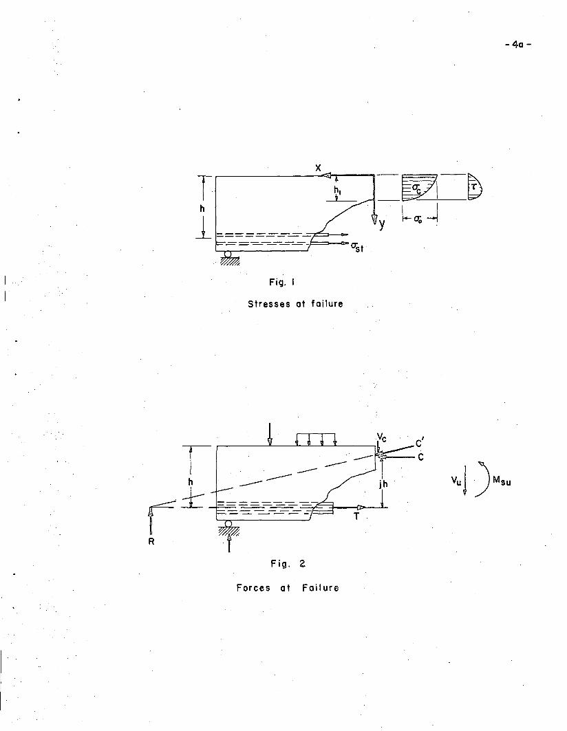
in the following. tvithout anticipating a more detailed
discussion, it may be a.ssumed that failure occu-rswhen the
concrete normal stress at the extreme compression fiber of
the prospective failure section reac.hes some cri.tical value
0-0 (see Figure l), which for the time being is suppose.d to
be known. It will be seen that the shearing strength may
be specified by the moment Msu and the shear force Vu acting
at the failure section (Figure 2)0 In. order to determine
these quantities~ it is necessary to obtain information
concerning the distribution of the no:r:'mal stresses (j and
of the shearing stresses~, the relation between sectional
(1)=
forces and stresses being given by the equilibrium conditions
l-LdA
= cIA (2)
where A denotes the entire failure section o One can further-
more make use of the
fAa- dA
third equilibrium condition
= 0 (3)
and of the generally accepted simplifying assurnptions~
R
Th
1
x
Fig. I
Stresses at failure
------Fig. 2
Forces at Fai lure
-40 -

= 5 =
1) The shear transfer along the diagonal crack
is neglected
2) The. shear transfer of the longitudina.l rein=
forcement is neglected
With all the above conditions, the stre.ngth Msu and Vu would
be determined, if the location of the neutral axis (hl) and
the shape of the stress distribution curves were known.
Since the distribution o£1: can immediately be related to
that of ~ by equilibrium conditions of vertical strips
(Ref 5), one is left with essentially two unknown factors~
the depth of the neutral axis and the shape of the normal
stress block. A great number of investigators have immorta~
lized their names by assuming different stress blocks. It
must be said; however , that the deviations in. the calculated
ultimate moment resulting from various reasonable choices
are rather small. Thus the depth of the neutral axis can
be considered as the only significant missing link for
the determination of the ultimate shear strength.
As is sufficiently known, the depth of the neutral axis
(hl ) for pure bending is found with the aid of Navier Bernoullius
hypothesis that plane cross-sections remain plane after de=
formation, a hypothesis which is sometimes referred to as
strain condition, compatibility condition or deformation con=
- 6 -
dition, the latter term being used in this paper. This hypo
thesis is not applicable for the region subjected to moment
and shear, especially not after formation of diagonal cracks.
1a this light, the particular theoretical difficulty of the
problem of shear can be attributed to the lack of knowledge
of an appropriate deformation condition.
The aim of this paper is to derive a theory of shear
failure, by proposing a theoretically founded deformation
condition. As will be shown, the shear strength of prestressed
concrete can be based on the strength of similar unprestressed
members. Thus it was deemed advantageous to state the
theory first for the simplest case of COBventionally rein
forced concrete and then to generalize it for prestressiBg
as well as for web and co~pression reinforcement. In addition
to the variables taken into account by most investigators, the
influence of bond and the influence of the state of stress i~
the concrete are considered. These measures do not make the
theory more complicated; on the contrary they permit a rational
explanation of phenomena which so far had to be derived empi
rically.
Before proceeding to the actual theory, some notions
about the ultimate strength in general will be clarified.

- 7 -
Most of the investigations dealing with the ultimate strength
of concrete structures, including this one, are confined to
the strength of critical cross-sections, but they do not
furnish an estimation of the strength of the structure as a
whole, except in special cases, for example statically de
terminate members. As for the strength of a cross-section
under the combined action of moment and shear, abbreviately
but somewhat unprecisely called "shear strength", it is often
given either by the moment Msu or by the shear force Vu ' This
stems probably from the fact that most tests are performed
with symmetrical two point loading, where the relative
magnitude of M and V is immediately determined by the "shear
span" (a), i.e. the distance between load and support. Yet,
for more general cases, it is necessary to consider 'the com
bination of moment and shear, because both have a di.stinct
influence on the shear strength. Since it would be rather
inconvenient, however, to list always two quantities for the
strength, the latter is expressed in this paper primarily as
a moment capacity, which in order to recognize the influence
of the shear force, is made a function of the relative magnitude
of moment and shear, i.e. of the ration M/Vh. This is possible
by theoretical considerations, in that the ulti.mate concrete
stress (To can be derived as a function of M/vYh.. As for the
-\
- 8 -
designation of this moment capacity Msu ' the correct but
somewhat lengthy term "ultimate moment of a cross-section
under the combined action of mome.nt an.d shear" is abbrevia
ted to "ultimate shear-moment".

- 9 -
THEORY OF SHEAR FAILURES FOR CONVENTIONALLY REINFORCED
BEAMS WITHOUT WEB AND COMPRESSION REINFORCEMENT
Basic Concept
Some of the simplifying assumptions which will be
employed to state the hypothesis about the mechanism of
shear failures may be noted as being quite arbitrary.
However, the relevancy of the resulting theory should not
primarily be judged by the accuracy of these assumptions,
but by the accuracy of the final result. As will be· seen,
the latter is relatively insensitive to errors in the said
assumptions. It might be recalled that similar conditions
prevail for bending: after cracking the hypothesis of plane
cross~section is quite unrealistic (see Ref 5, page 12),
yet it furnishes reasonable estimates of the ultimate bend
ing strength.
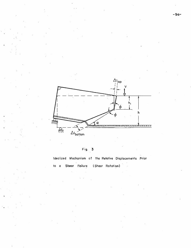
The hypothesis for the mechanism of shear failures is
proposed as follows:
The deformations of a beam in the vicinity
of a diagonal crack stem from a "shear
~otation ¢", i~e. a rotation about the as
yet unspecified end of the diagonal crack
(see Figure 3).
h
~--~~~~~~/. .6.lbottom
Fig. 3
Idealized Mechanism of the Relative Displacements Prior
to a Shear fai lure (Shear Rotat ion)
-90-

......
- 10 -
The failure section is idealized to two planes:
a vertical plane from the center of rotation to the top
of the beam and an oblique plane along a diagonal crack
forming an angle ~ with the beam axis. All the diagonal
cracks which may form in the vicinity of the failure
section are imaginarily merged to the one crack in the
failure section. The zone of flexural bending (in
Fi.gure 3· the portion to the right of the failure section)
i.s assumed to be rigid. The sectional forces V and Mare
taken with respect to the center of rotation.
These basic assumptions permit the formulation
of a deformation condition. From Figure 3 it can be
seen that the shortening of the concrete top zone has to
be
(4)
and the elongation of the bottom zone, attributed to a
pull-out effect of the reinforcement relative to the
concrete becomes
Hence
(5 )
sino< (6)

- 11 -
This deformation condition can now be considered as a sub-
stitute for Navier-Bernoulli's hypothesis. Notably, the
former is stated in terms of finite deformations and not, as
the latter, in terms of strains. This measure is necessary
because the strain concentration associated with shear
failure requires a consideration of the deformations in the
whole region of the prospect~ve shear failure.
Otherwise the structure of Eq. 6 is similar to
Navier-Bernoulli's hypothesis
E:. top
E:. bottom= (7)
The next question is now, obviously, to determine the de-
formations ~ltop and ~ lbottom'
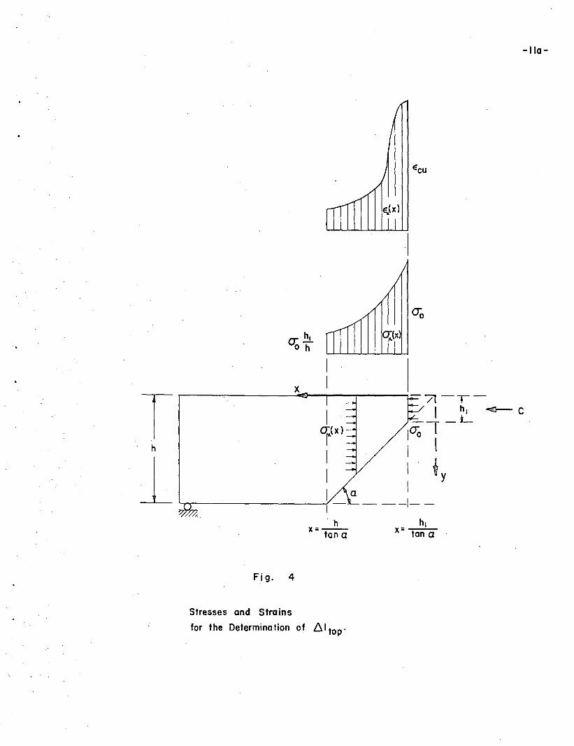
The Deformation of the Concrete Top Fiber
By using the no'tation given in Figure 4 and by neglect-
ing the small deformations outside the region of the diagonal
crack, the contraction of the concrete top fiber can be
expressed ash
l:::. ltop =Jt:u:(x;y = 0) dx
hltano<
(8)
%:.
o:.!!Lo h
Fig. 4
I
hix= tan a
-110-
Stresses and Strains
for the Determina tion of LJ,I top'

- 12 -
Only one point of the curve~(x;y = 0) is known beforehand,)(
i.e. the ultimate compressive strain~cu will certainly
occur at the location of crushing, thus
~lEx (x = tan a::.; y = 0) = E cu (9)
In order to approximate the shape of the strain distribution
curve Ex(x;y = 0), it is assum~d that the stress distribution
in each vertical section of the concrete wedge be uniform
(see Figure 4). On account of equilibrium the resultant of
each stress block must equal the concrete compressive force C/
(10)
or()x (x) hl= 0""0
xtan~(11)
These normal stresses ~x(x) are converted to strains with
the aid of the parabolic stress-strain relationship
·tt = 2\ _~2 (12)
or
P13 = 1 - (13)
where 1 = ax-00
SEx
- --E.cu
The strain distribution along the concrete top fiber (Figure 4)/-....··
can thus be obtained by substituting Eq. 11 in Eq. 13.

- 13 -
._~..
l /1 - ,]E = ccu ..1 -
hlx tan ()(x
henceh
r. ran~ J h 'l.6 ltop = ccu 1 - 1 dxx tano<,
hltanG<
the solution of Which is
(14)
(15 )
6 cu h= tan 0(
hl Rhl hl1 - - - 1 - -" + - lnh " h 2hJ h I
1 + 1 - If1-)1 _fir
. h
(16)
The Deformation of the Bottom Zone
As mentioned before,the elongation of the bottom
zone is attributed to a pull-out effect of the longitudinal
reinforcement with respect to the surrounding concrete. Since
this pull-out effect is obviously a function of the bond char-
acteristic, the influence of bond will enter the considera-
tions. On the other hand, a new variable is added to the
already complicated problem -- a variable which from experience
is known to be accompanied by considerable scatter.
Observations of actual pull-out tests (5) suggest that
1 0. 2A bottom = 1\ Est (17 )
where A depends on the bond characteristic. The reciprocal
- 14 -
of ~ ) i.e. ~, will hereafter be called '~ond coefficient".
Conventional pull=out tests do not directly represent the
magnitude of 6..lbottom' since due, to the rotation r/J the
resulting tension force does not act in the direction of,
the tendons. The coefficient A will therefore take on a
greater value than for axial pull-out.
Solution
By assuming a rectangular stress block of the magnitude
~o over the concrete compressive zone the ultimate shear
moment becomes
(18)
This expression contains only one unknown, i.e. hl. An equa
tion for hl is therefore regarded as the solution of theh
problem. Similarly to pure bending, this solution is obtained
by combining the deformation andequilibrium conditions.
The deformation condition derived before can now
be transformed to an expression in terms of strains, namely
Sst ~C~an~sin~l~l-l)(I=,:r ~ii~'~+ :~ in~~~]~19)obtained by substituting Equation 16 and 17 in 6.
The equilibrium condition requires that the com-
pressive force C must beequal and opposite to the tension
- 15 -
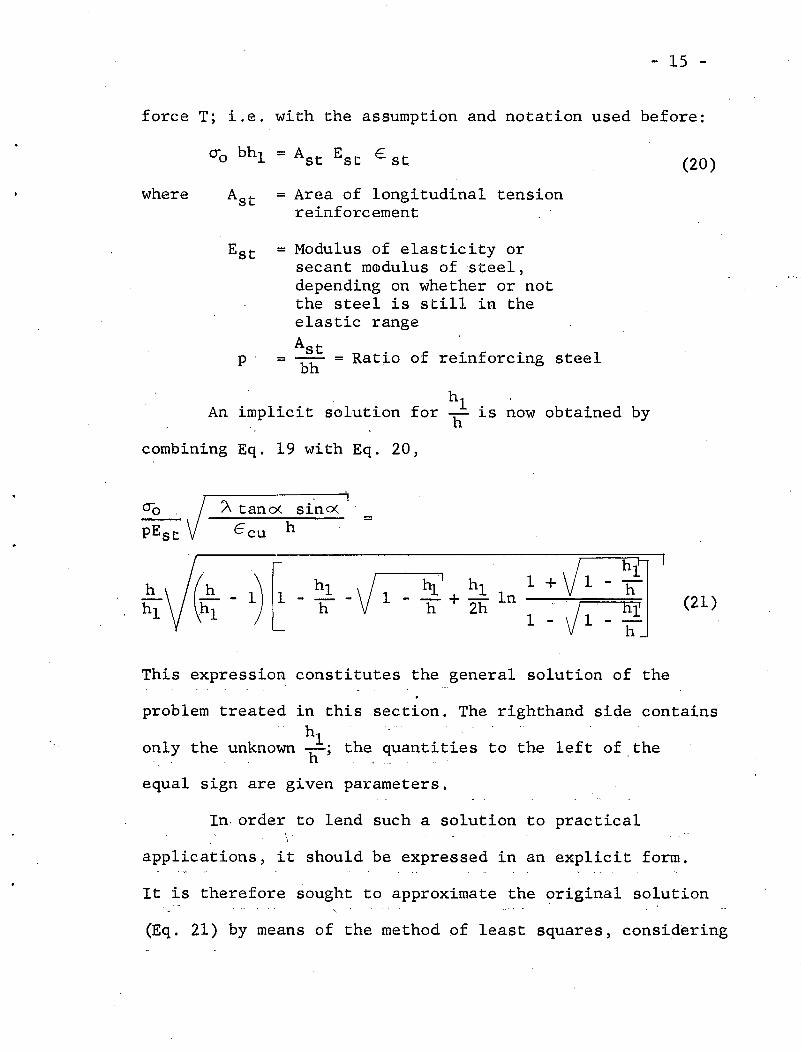
force T; i.e. with the assumption and notation used before:
(20)
where = Area of longitudinal tensionreinforcement
p.
= Modulus of elasticity orsecant mIDdulus of steel,depending on whether or notthe steel is still in theelastic rangeAst= ---- = Ratio of reinforcing steelbh
(21)
An implicit solution forhI
is obtained by11 now
combining Eq. 19 with Eq. 20,
"0 J " tan ()( sino< =pEst t=cu h
- 1)t- hJ.' hIh hI -V 1 1 +hI 11 11 + 2h In Jl1
This expression constitutes the general solution of the
problem treated in this section. The righthand side contains. h
only the unknown hI; the quantities to the left of the
equal sign are given parameters.
In. order to lend such a solution to practical
applications, it should be expressed in an explicit form.
It is therefore sought to approximate the original solution
(Eq. 21) by means of the method of least squares, considering

- 16 -
also the weight of any portion of curve according to the
relative probability of occurrence. By this procedure it
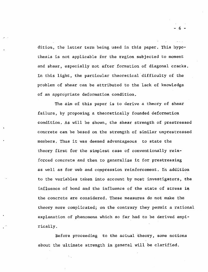
was found that
(22)
(23)
constitutes an approximation so accurate as to lie within the
thickness of the original curve, shown in Figure 5,.
Thus the explicit solution can be written as
=0.75
1
1.65(24)
It was thus possible to determine the ultimate shear
moment by a theoretical approach, the adaptibility of which-:"./ -
has of course first to be demonstrated by comparison with
test results.
For later use it is convenient to trace this solution
once again back to the deformation condition. An exactly
identical solution to Eq. 24 could be obtained by taking
( 1-0.75 ~YEcu h 1.65
6. ltop= tan ex:. h (25)(hl - 1)

403020
0"0 Ata" a sinapE Ecu h
10
\ . h' I
Solution:h (.!!--H-~ -JI- II, I + .!!L In 1+ 1-T jq=- -hI hI h h. 2h I-JI-'&
. h
Explicit Approximation: hi I-:h 0.75q + 1.65
-" -\
~I!
.........
""-----
o 0
0.5
0.4
0.3en'i( e0 .,e CD- .a~ -4». 0C- .c 0.20 a.c (l)
a "CI4»
"CI
"£I.c
0.1
Fig. 5 Solution for h.!h as a function of the given parameters
0;; Est' a; Ecu and h.eno•

form
- 17 -
i
This brings the deformation condition to the simple
hI1 1.65 11
est = ---=-=-=---.0.75
Ecu hA sino( tanQ(. (26 )
This expression is later used to derive the formulas for
more complicated cases.
/
~ 18 -
GENERALIZATION FOR PRESTRESSING WEB
AND COMPRESSION REINFORCEMENT
Prestressing
The approximate knowledge of the failure mechanism,
gained by the preceeding approach, permits a direct de=
termination of the influence of prestressing. This feature
is especially favorable because the shear strength of
prestressed beams can reliably be related to that of un-
prestressed beams, thus sparing the need of experimentally
verifying the influence of all other variables already
aggravating the research of conventionally reinforced con-
crete.
The initial state of 'stress, produce.d by the pre-
stressing, forbids a direct application. of the deformation
condition stated in the last chapter. Rather than change
the deformation condition itself, one can introduce fictit-
ious strains which compensate the initial state of stress.
The following notations will be used for these considerations:
E 0
~ elastic shortening of the concretedue to prestressing
- fictitious strain which, appliedat the centroid of the tendons,would relieve the concrete stresses
E.eff - effective prestressing strainafter deduction of all thelosses
- 19 -
Since the initial state of stress is caused exclu-
sively by the prestressing (the stresses due to dead load
are not considered as initial stresses, even though they have
to be taken into account for the calculation of the prestress-
ing losses), it must be possible to relieve these stresses
by applying a fictitious strain €o ~t the centroid of the
prestressing tendons. This strain has to be larger than the
effective prestressing strain, since the elastic losses have
to be overcome (but not the inelastic losses which remain
as residual strains without causing stresses). Thus .the
fictitious strain is
~ 0 = ~eff +~~el
The external moment M, acting at a prospective
failure section, can always be split into a couple,
(27)
T = C = M h = E..stAst E":It (28)
(h - 21
)
The strain corresponding to the tensile force acting at the"
centroid of prestressing can be imagined to consist of two
parts,
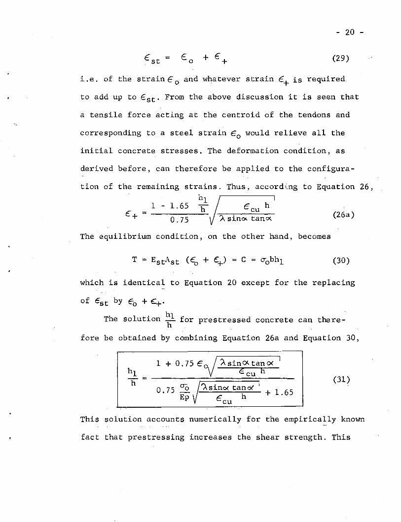
- 20 -
€st = Eo + e + (29)
i.e. of the strain eo and whatever strain e+ is required
to add up to 6 st ' From the above discussion it is seen that
a tensile force acting at the centroid of the tendons and
corresponding to a steel strain Eo would relieve all the
initial concrete stresses. The deformation condition, as
derived before, can therefore be applied to the configura-
A sinoc.. tano<..
tion of the Thus, according to Equation 26,,
(26a)Ccu h
remaining strains.hl
1 - 1.65 11c+ = -----
0.75
The equilibrium condition, on the other hand, becomes
(30)
which is identical to Equation 20 except for the replacing
of Cst by ~o + ~+.
The solution hl for prestressed concrete can thereh _
fore be obtained by combining Equation 26a and Equation 30,
(31)
+ 1.65I'A sino< tanO<'
6 cu hEp5 000.7
1 + O. 75 Eoj ). s in ()I.. tan 0< IE cu h
This solution accounts numerically for the empirically known
fact that prestressing increases the shear strength. This
- 21 -
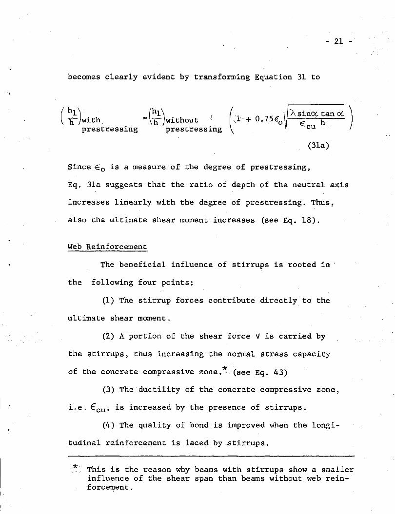
becomes clearly evident by transforming Equation 31 to
(:1}With =(:1)without ..~prestressing prestressing (
J--+, O. 75 Eo Asincx.. tan ex:. )E cu h
(3la)
I '
Since Eo is a measure of the degree of prestressing,
Eq. 3la suggests that the ratio of depth of the neutral axis
increases linearly with the degree of prestressing. Thus,
also the ultimate shear moment increases (see Eq. 18).
Web Reinforcement
The beneficial influence of stirrups is rooted in '
the following four points:
(1) The stirrup forces contribute directly to the
ultimate shear moment.
(2) A portion of the shear force V is carried by
the stirrups, thus increasing the normal stress capacity
*'of the concrete compressive zone. '. (see Eq. 43)
(3) The ductility of the concrete compressive zone,
i.e. ecu ' is increased by the presence of stirrups.
(4) The quality of bond is improved when the longi-
tudinal reinforcement is laced by.stirrups.
:*: This is the reason why beams with stirrups show a smallerinfluence of the shear span than beams without web reinforcement.
- 22 -
For the time being, only the first two points are
considered numerically, since first, Ecu does not affect
the ultimate shear moment significantly, ;and second, only
qualitative information concerning the improvement of the
bond due to stirrups is available at present.
Actual measurements of the stirrup forces by means
of strain gages peFmit the conclusion that the stirrups
crossed by the diagonal failure crack reach or surpass the
yield point of the steel, thus sparing the need for a
consideration of the shear rotation 0.*
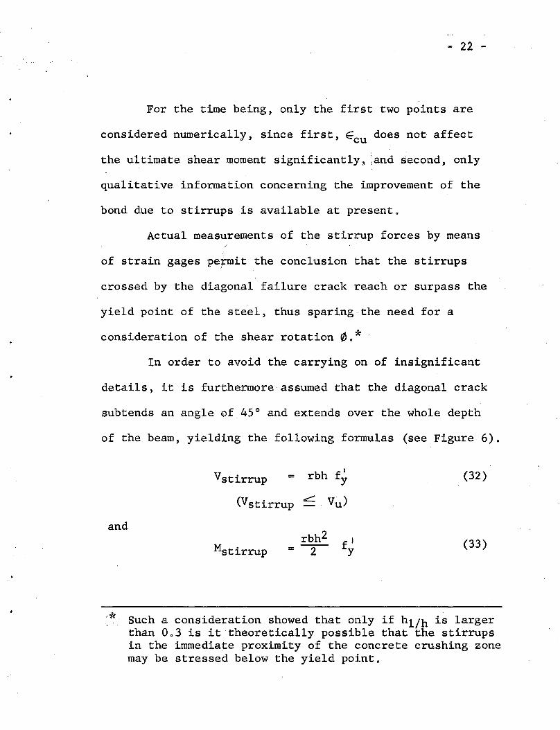
In order to avoid the carrying on of insignificant
details, it is furthermore assumed that the diagonal crack
subtends an angle of 45° and extends over the whole depth
of the beam, yielding the following formulas (see Figure 6).
Vstirrup =Irbh f y (32)
and
(Vstirrup c:: Vu )
Mstirrup = flY
(33)
*. Such a consideration showed that only if hl/h is largerthan 0.3 is it theoretically possible that the stirrupsin the immediate proximity of the concrete crushing zonemay be stressed below the yield point.

Fig. 6
IIII'"
IIII
I".: ) Mstirrup
1---- ~ -iI
Vstirrup III
h -I
-22.q-
Simplified Assumption for the' Computation of the
Stirrup Moment (M stirrup)
- 23 -
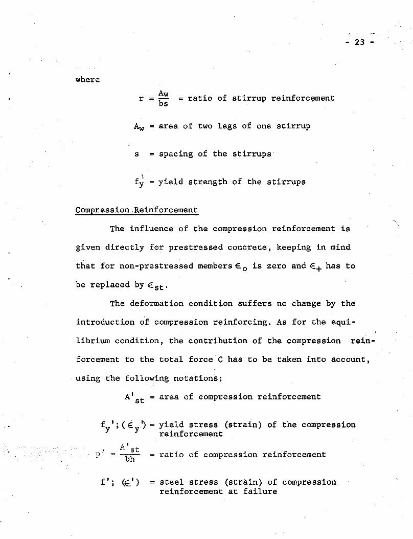
where
Awr = bs = ratio of stirrup reinforcement
Aw = area of two legs of one stirrup
s = spacing of the stirrups
f 'y = yield strength of the stirrups
= ratio of compression reinforcement" '*
Compression Reinforcement
The influence of the compression reinforcement is
given directly for prestressed concrete, keeping in mind
that for non-prestressed members E. o is zero and E+ has to
be replaced by Est-
The deformation condition suffers no change by the
introduction of compression reinforcing. As for the equi-
librium condition, the contribution of the compression rein-
forcement to the total force'C has to be taken into account,
. using the following notations:
A'st = area of compression reinforcement
f I; (~ ') = yield stress (strain) of the compressiony y reinforcement
A'stn' ='"~ btl
fa; (~') = steel stress (strain) of compressionreinforcement at failure
- 24 -
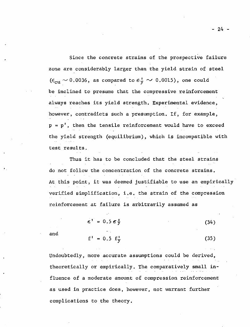
Since the concrete strains of the prospective failure
zone are considerably larger than the yield strain of steel
(Ecu r-..J 0.0036, as compared to E y rv 0.0015), one could
be inclined to presume that the compressive reinforcement
always reaches its yield strength. Experimental evidence,
however, contradicts such a presumption. If, for example,
p = p', then the tensile reinforcement would have to exceed
the yield strength (equilibrium), which is incompatible with
test results.
Thus it has to be concluded that the steel strains
do not follow the concentration of the concrete strains.
At this point, it was deemed justifiable to use an empirically
verified simplification, i.e. the strain of the compression
reinforcement at failure is arbitrarily assumed as
c' = 0.5 €y
andf' = 0.5 f'y
(34)
(35 )
Undoubtedly, more accurate assumptions could be derived,
theoretically or empirically. The comparatively small in-
fluence of a moderate amount of compression reinforcement
as used in practice does, however, not warrant further
complications to the theory.

~ 25 -
On account of the above simplifioations~ the eqai1i-
brium condi.tion of the horizontal sectiona,l for.ces becomes ~
(36)
Consequently the solution for hl/h is obtained by
substituting Equation 36 in Equation 26a~
c h ~yU..0. po\:.. cu 0 I;:
A sino< tan 0<.- - ~ 2p
(37)
C/o
pE1~65+ 0 0 75 ")\ sino' tan 0<.
{)
This is now the most general solution for the ratio hl/h o
The compression reinforcement has» naturally, also
to be taken into account for the formulation of the u1ttimate
shear moment, which~ by including the contribution of ver-
tical stirrups, becomes
_. 2 ~( . hl ,p 0 f y ) ,. h1 rfy] .'- bh CT"o - + - (l~ _ ) +._o_ ",i
. .' h·, 2 2h." ',2, '_contributio~ contr'ibution' c~niributionof the beam of compressive of stirrups
reinforcement
(38)

- 26 -
THE INFLUENCE OF THE MAGNITUDE OF THE SHEAR FORCE
In the foregoing theory the ultimate shear moment
Msu was derived without explicitely regarding the in-
fluence of the magnitude of the shear force. It was,
however, mentioned that this influence can be traced back
to the normal stress capacity (~o) of the concrete com-
pressive zone. Due to the presence of shear the state of
stress in this zone is not anymore linear as in the region
of pure bending. It follows, therefore, that 00 does not
only depend on the linear concrete strength (given for
example by fb), but is a function of the prevailing state
of stress, the latter in turn being determined at any
point of the failure section by the relative magnitude of
(J and 't. Hence
0-0 F (f~0":
(39)= \:')
or stipulating that 0- be a function of C (see Figure 2)'"t Vc
0-0 = F (f v .• .£.) (39a)c , Vc
The rather involved deriva~ion of this last relationship,
presented in detail in Ref,S, is only outlined herein, some
simplification is also introduced which results in a slightly

- 27 -
different equation for ~o than that given in Ref 50 The
simplification pertains to the selection of the stresses
to which a suitable failure criterion will be applied o
It is here assumed that the resistance of the concrete
compressive zone is exhausted when the average of the
normal stresses (~av) together with the average of the
shearing stresses (Tav) satisfy the well known failure
criterion for plain. concrete proposed by Mohr (6) some
50 years ago o
By assuming that
(1) The failure envelope is a parabola of the
second order
(2) The linear tensile strength is one eighth
of the cylinder strength (f~)
and by neglecting vertical normal stresses which may occur
in the vicinity of vertical loads, the said criterion for
the range of stresses here of concern can be written as
(see Ref 5)
(fI )2 (J 21:)2fT+(~
c c= 0 (40)
where ~ and l' denote respectively the normal stresses and
shearing- stresses on a surface element normal to the beam

- 28 -
axis. Since it was stipulated that the average stresses
C'".'
and
CJav =
(41) ,
sati.sfy the failure criterion) Equation 40 can be written
asVc \2
C ) = 0
or (42)
For practical applications it is convenient to estimate the
ratio VC / C beforehand, thus avoiding a lengthy determination
by successive approximation. This may be achieved firstly
by neglecting all shear transfer other than that of the con-
crete compressive zone and secondly by assuming the lever
arm of the internal couple to be 0.9 h
Hence <To becomes approximately
f~
. ..) ~.e.~
(43)
* This assumption i.s only usea to estimate <Yo, but not for adirect determinati.on of Msu '

..
- 29 -
Thus besides its effect on the crack pattern, the presence
of shear reduces the normal stress capacity of the concrete
compressive zone (Figure 7). Retrospectively it can further
more be seen that this theoretical approach accounts for
the often discussed influence of the shear span (a), in that
for symmetrical two point loading the ratio M/Vh can be
replaced by a/h. There is, however,."a distinct advantage
in maintaining Eq. 43 in its present form, since it may
be applied to more general loading conditions. It was even
found, that the influence of end restraint can be con
sidered with reasonable accuracy by merely observing the
reduction of ao according to Eq. 43 .

-290-
2 :3 4
M/Vh
Fig. 7
<To I- =f'
1+ 3( V:)2c
-
~
//'
v
Iv
j'
,//
"'"oo
0.2
0.4
0.8
1.0
0.6
- 30 -
ASSESSEMENT OF PARAMETERS AND COMPARISONWITH TEST RESULTS
In order to compare the theory with test results, it
is necessary first to determine the various parameters used
in the previous derivations. These parameters may be divided
in the four following categories:
1. Geometrical properties (p, pI, r, h). M .
2. Loading conditions ( Vb; Eo),
3. Material properties (E, f~, E;, ccu)
4. Composite properties (0(, '>.. )
The geometrical properties need no further explanation; they
are defined in the list of notations.
The degree of prestressing, expressed by the quantity
Eo (see Eq 27) can be determined using any suitable method
which accounts for the losses of prestress. If the prospec-
tive failure section is not predetermined by the loading
condition, the critical ratio of'M/Vh has to be found by
trial and error. In most practical cases, however, it is com-
parative1y easy to forecast the approximate location of
failure.
The material constants are readily obtained from
standard tests. The quantity E may be either the modulus of

/
~ 31 -
elasticity or the secant modulus, depending on whether
or not the longitudinal reinforcement is stressed beyond
its elastic limit. If this limit is exceeded, which may
be the case for low percentages of reinforcement or for
high degrees .of prestressing, the E-modulus has to be
approximated successively. In view of the relative in
sensitivity of Msu to the ultimate concrete strain, and
since the latter is di~ficult to measure precisely, the
following assumption is made
E"cu = 0.0036
The development of diagonal cracks was found to .
be governed by the shape of the stress trajectories. For
practical applications, it would, however, be too involved
to base the prediction of the inclination of diagonal
cracks on these trajectories. It is therefore assumed that
0( = 45°
Some justification to this ~implificationmay again be
attributed to the fact that the equation for Msu is not
very sensitive to variations inoc.
While considerations of the above kind pertain to
most of the recent investigations, a new element is intro
duced by the anticipated determination of the influence
of bond. The great number of factors affecting the bond

- 32 -
characteristic required a detailed investigation (see
Ref 5), yielding the following relationship
(44)
whered = diameter of longitudinal bars, wires or strands
and
~ = coefficient of roughness.
Not Rusted Rusted -
Plain Round Bars 5.5 4.0
Deformed Bars 3.0 2.0
Strands 2.0 1.5
These tentative values were obtained from standard pull-
out tests in comparison with actual beam tests.
Now that the means are given, the ultimate shear
moment Msu can be computed by consecutively using
Eq. 43, 44, 37, and 38. Theoretical estimates were compared
with about 300 test results which could be found in the more
recent literature. The investigations considered for this
comparison are given in the List of References under a sepa-
rate heading. The agreement of theory and tests may be
judged by the ratiosMsu calculatedMsu test

- 33 -
which are summarized in Figure 8. It will be notic~d, that
the peaks of the frequency curve of Mcalc/Mtest lie in
general somewhat below unity. This is not surprising since
various assumptions on which the theory is based had been
chosen conservatively.
In view of the scattersome nature of shear failures,
the theoretical estimates may be deemed satisfactory.
.. , .- '~'.

25 .-------r-------.----.....,------.:.----t----,---.---,
20 f------f-----1-.-......../.-+---l-----f-----+-----f.. I ''\
'I ',\: I, ',\: I
" \
-330-
15enen~o~IO
,Q
E='z
5
o0.4 0.6 0.8 1.0
Mca1c
.M test
1.2 1.4 1.6
N m (J'
-.- Simply supported j no web orcomp. reinf. 52 0.96 0.15_ ..- Simply supported j with compo reinf. 30 1.04 0.15.......... Simply supportedj with web reinf. 59 0.90 0.12
-._---- T Section .20 1.04 0.18Pres tressed 32 0.80 0.10
---- Restrained 85 0.94 0.17TOTAL 278 0.94 0.16
Note: N = number of tests
m = mean value of Mca1c /.(J' = standard deviation / Mtest
Fig. 8
Frequency Curve of the RatioMcalc
Mtest
•
- 34 -
SUMMARY AND RECOMMENDATION
(1) The prediction of the ultimate strength of prestressed
and conventionally reinforced concrete beams under the
combined action of moment and shear was approached by
stating a hypothesis concerning the failure mechanism
in' the' region of diagonal cracks.
(2) The failure mechanism is considered to consist of a
I1 shear-rotation" 6. about the neutral axis of the
broken failure section. The depth of the neutral
axis at failure could then be obtained by observing
(a) the deformations caused by the shearrotation;
(b) the critical stresses resulting fromthese deformations; and
(c) the equilibrium conditions of the internal forces.
(3) The failure is ultimately attributed to the destruction
of the concrete compressive zone. The strength of this
zone, depending on the prevailing state of stress, was
derived according to Mohrts failure criterion for plain
concrete.
(4) The deformation of the tension zone was attributed to a
pull-out effect of the longitudi~al reinforcement rela
tive to the surrounding concrete. This measure permitted

- 35 -.
a numerical consideration of the influence of the
bond characteristic on the shear strength.
(5) The information concerning the ultimate strength of a
bea~ is expressed in terms of moment capacity (ulti-
mate shear moment), while considering, however, the
influence of the magnitude of the shear force
( ~ ratio)~.
(6) The comparison with 278 test results confirmed the
satisfactory validity of the theory for:
(a) Simply supported beams with 'andwithoutweb or compression reinforcement
(b) Prestressed beams
(c) Restrained beams
(d) Beams of various cross-sections
(7) According to the theory and in agreement with experimental
findings, the ultimate shear moment increases with
(a) concrete strength;
(1) ) ratio of tension reinforcement;
(c) ratio of web reinforcement;
(d) ratio of compression reinforcement;
(e) p.restressing;
(f) bond coefficient l/~; and
(g) ratio M/Vh '(for symmetrical loading:shear span).
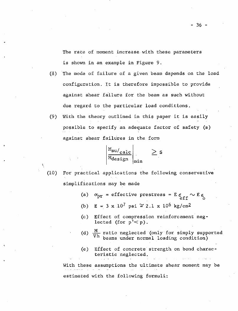
- 36 -
The rate of moment increase with these parameters
is shown in an example in Figure 9.
(8) The mode of failure of a given beam depends on the load
configuration. It is therefore impossible to provide
against shear failure for the beam as such without
due regard to the particular load conditions.
(9) With the theory outlined in this paper it is easily
possible to specify an adequate factor of safety (s)
against shear failures in the form
\.
Msu/ calc > SMdesign. min
(10) For practical applications the following conservative
simplifications may be made
O:;pr = effective prestress = E c rv E €.eff 0
E =3 x.107 psi ~ 2.1 x 10⁶ kg/cm2
(a)
(b)
(c) Effect of compression reinforcement neglected (for p '< p) .
(d) .1L ratio neglected (only for simply supportedVh beams under normal loading condition)
(e) Effect of concrete-strength on bond characteristic neglected.
With these assumptions the ultimate shear moment may be
estimated with the following formuli:

-360-
2.5 ..--------.---------,,-------.----------,--/---:-"'----,
a = 36"
p =I %
f ' .c= 5000 pSI
Reinf. = # 5
ReferenceBeam
03 4 50 CD I 2
Ratio of tension reinforcement p (%)
I ! I I !
®I 2 3
(x 10- 3 in/in )4 5
Degree, of prestressing EoI ! ! I !
@ 0.5 I 1.5 2.0 2.5Ratio of st irrup reinforcement r (%)
! I I ! !
@ 0.2 0.4 0.6 0.8 1.0
Ratio of compression reinforcement,
(%)p! ! !
® 2 4 6 e 10Concrete strength f I (ksi)c
I ! ! ! ,
® 2 4 6..M- e 10
RatioVh
I , I I ! I
(j) 2 4 6 8 10
Bond coefficient '/,\ (10-5 in- 1 )
Fig. 9Rate of Influence of Various Parameters
0.5 ll--+---I:L...:;~-+------+-
1.5
2.0 ll-----,----+-----f----,--~I!:..---b~-----t--;;;;"'--___j
ec:ICDm- CD
C UCD cE e0 lD-:liE CDa:.. -c:I 0CD
.&:C(I)(l)
CD e0
C ~e- ..0
:::) CD.&:(I)-:5
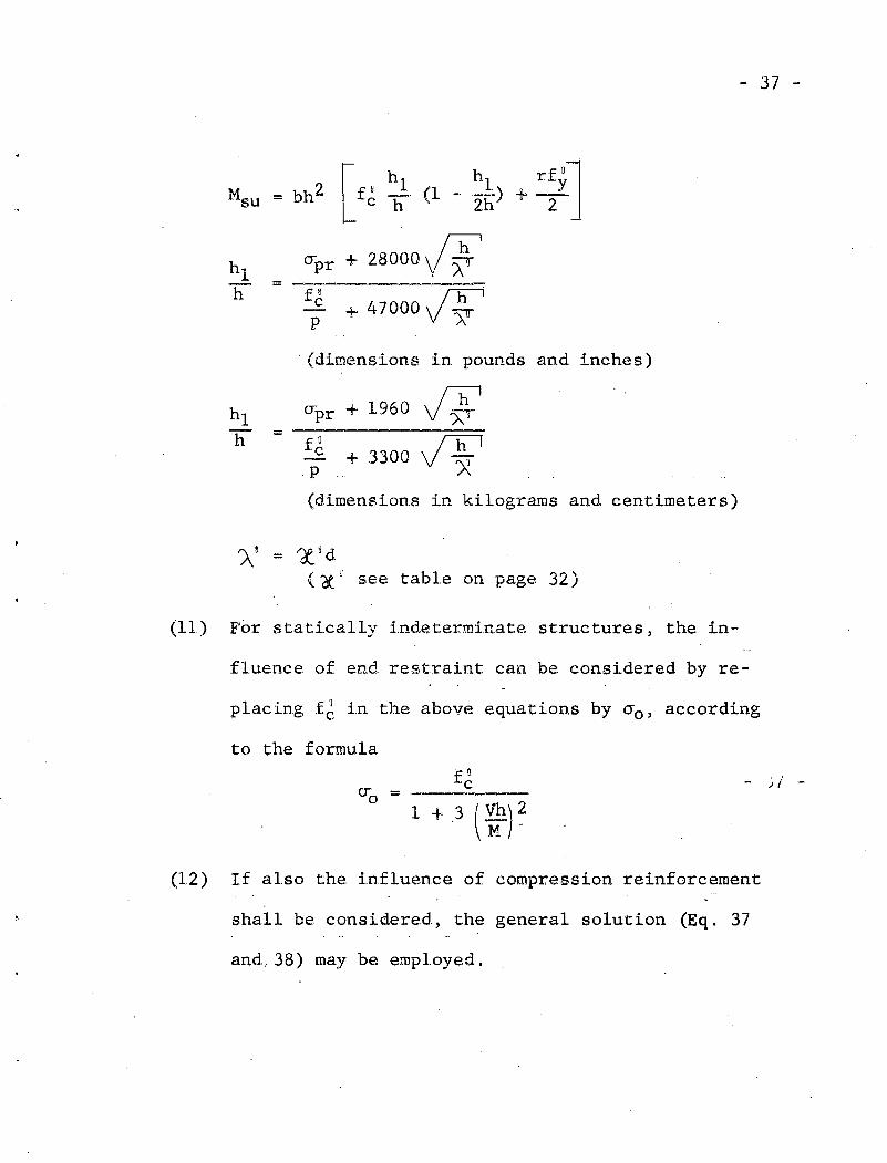
Msu bh2 [f" h 1 (1 _ h1 ) rfyl= +-c h 2h 2
hlCTpr + 28000~
11 = -fij47000~c
p + All
- 37 -
.p
CTpr + 1960
fUc + 3300
=
. (dimensions in pounds and inches)
J~I
J~I
(dimensions in kilograms and centimeters)
A! = ,,£°d( 6{ ° see table on page 32)
(11) For statically i.ndeterminate structures, the in-
fluence of end restraint can be considered by re-
1 . fn. h b . b d'p ac~ng . c 1.n t. e a ove equat1.ons y 0"0' accor ~ng
to the formula. 0f c
ero = ------
1+.3(~)~
- .J i -
(12) If also the influence of compression reinforcement
shall be considered., the general solution (Eq. 37
and, 38) may be employed,

- 38 -
REFERENCES
1. Freudenthal, Alfred M. "Safety and Probability ofStructural Failure',' ASCE Transactions Vol. 121, 1956.
2. Hulsbos, ·C.L. and Irwin, F.G.E. Shear Strength ofPrestressed Concrete I-Beams Without Web ReinforcementProgress Report, Iowa Engineering Experiment Station,Iowa State College, Jan. 1957.
3. Hognestad, E. What Do We Know About Diagonal Tensionand Web Reinforcement in Concrete? University ofIllinois Bulletin, Vol. 49, No. 50. March, 1952.
4. Laupa, A.; Siess, C.P.; Newmark, N.M. Strength inShear of Reinforced Concrete Beams. University ofIllinois Bulletin, Vol. 52, No. 55. March, 1955.
5. Walther, Rene E. The Ultimate Strength of Prestressedand Conventionally Reinforced Concrete under the Combined Action of Moment and Shear Fritz EngineeringLaboratory, Report 223.17, Lehigh University, Oct. 1957.
6. Mohr, 0. "Die Schubfestigkeit des Betons." ArmierterBeton..; 1911
Investigations Considered for Comparison of Theoryand Tes!:.~
Moody, K.G.; Viest, I.M.; Elstner, R.C.; Hognestad, E."Shear Strength of Reinforced Concrete Beams. 'I A.C. I.Journal. Vol. 26, No.4 (Dec., 1954), No. 5 (~an.,1955),
No.6 (Feb., 1955), and No.6 (March, 1955).
Gaston, J.R.; Siess, C.P.; Newmark, N.M. An Investigation of the Load-Deformation Characteristics ofReinforced Concrete Beams Up to the Point of Failure.University::~p£LllinoisCivil Engineering Studies, Structural Research Series No. 40~December, 1952.
Clark, A.P. "Diagonal Tension in Reinforced ConcreteBeams." A.C.I. Journal, Vol. 48. October, 1951.

- 39 -
Gallet1y, G.D.; Hosking, N.G.; Ofjord, A. Behaviorof Structural Elements Under Impulsive Loads III.Mass. Institute of Technology Dept. of Civil and SanitaryEngineering. July, 1951.
A1-A1usi, A.F. "Diagonal Tension Strength of ReinforcedConcrete T~Beams with Varying Shear Span." A.C.I.Journa1,Vo •• 28, No. 11. May, 1957
Moretto, O. I~n Investigation of the Strength of WeldedStirrups in Reinforced Concrete Beams." A.C.I. Journal,Proc. 42:141~162. November, 1945.
Zwoyer, E.M. Shear Strength of Simply-Supported PreStressed Concrete Beams. Ph.D. Thesis. University ofIllinois: June, 1953.

II
Ast~
Astv
Aw
a
b
C
C'
d
:sJF
f'
fVc
fOy
h
hl
M
Mstir
Msu
p
p'
- 40 ...
NOTATIONS
Area of longitudinal tension reinforcement
Area of longitudinal compression reinforcement
Area of two legs of one stirrup
Shear span (distance between load and support)
Width of beam
Longitudinal compressive force
Inclined compressive force
Bar diameter
Modulus of Elasticity (or secant modulus) oflongitudinal tension reinforcement
Function
Steel stress of compression reinforcement at failure
Compressive strength of 6 x 12 in. concrete cylinders
Yield strength of steel
Effective depth of the beam
Depth of the neutral axis at shear failure
Bending moment
Moment contribution of the stirrups
Ultimate shear moment
Ast . f . . fp = bh = rat~o 0 tens~on re~n orcement
v _ Ast v • f fp - ~ = rat~o 0 compression rein orcement
r
s
T
v
r = Aw = ratio of stirrup reinforcementbs
Spacing of the stirrups
Tension force
Shear force
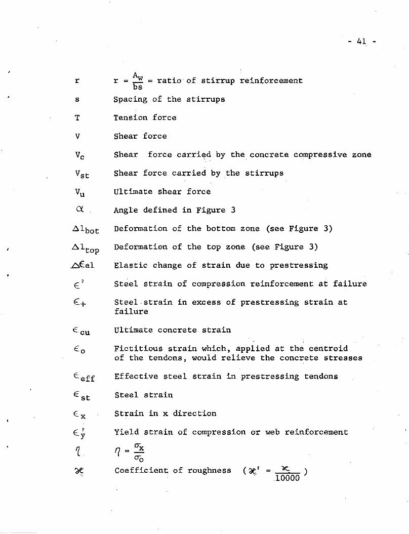
- 41 -
Vc Shear force carri~d by the concrete compressive zone
Shear force carried by the stirrups
Ultimate shear force
Angle defined in Figure 3
E:+
E. cu
Deformation of the bottom zone (see Figure 3)
Deformation of the top zone (see Figure 3)
Elastic change of strain due to prestressing
Steel strain of compression reinforcement at failure
Steel·strain in excess of prestressing strain atfailure
Ultimate concrete strain
Fictitious strain which, applied at the centroidof the tendons, would relieve the concrete stresses
Effective steel strain in prestressing tendons
Steel strain'
Strain in x direction
Yield strain of compression or web reinforcement
E. x
(.8Y
1 =eTxeTo
Coefficien~ of roughness (-~' - ~ )-10000

..Bond coefficient
f ~? == ~E cu
Normal stress
<x == ~A~10000
)
- 42 -
~av Average stress in the concrete compressive zone
~o Concrete normal stress at failure
ox Normal stress in x-direction
cry Normal stress in y-direction
T Shear stress
~av Average shear stress of the concrete compressivezone
Shear rotation