Embed Size (px)
Citation preview
Southern Illinois University CarbondaleOpenSIUC
Publications Department of Civil and EnvironmentalEngineering
1-2019
Shear Lag Factors for Tension Angles withUnequal-Length Longitudinal WeldsJen-kan Kent [email protected]
Saurav Shrestha
Follow this and additional works at: https://opensiuc.lib.siu.edu/cee_pubs
This Article is brought to you for free and open access by the Department of Civil and Environmental Engineering at OpenSIUC. It has been acceptedfor inclusion in Publications by an authorized administrator of OpenSIUC. For more information, please contact [email protected].
Recommended CitationHsiao, Jen-kan K. and Shrestha, Saurav. "Shear Lag Factors for Tension Angles with Unequal-Length Longitudinal Welds." AdvancedSteel Construction Volume 14, No. 4 ( Jan 2019): 589-605. doi:10.18057/IJASC.2018.14.4.
Advanced Steel Construction Vol. 14, No. 4, pp. 5xx-5xx (2018) 5xx
SHEAR LAG FACTORS FOR TENSION ANGLES WITH
UNEQUAL-LENGTH LONGITUDINAL WELDS
J. Kent Hsiao
1,* and Saurav Shrestha
2
1Professor, Department of Civil and Environmental Engineering,
Southern Illinois University Carbondale, Carbondale, IL, USA 2Former Graduate Student, Department of Civil and Environmental Engineering,
Southern Illinois University Carbondale, Carbondale, IL, USA *(Corresponding author: Email: [email protected])
Received: 18 June 2017; Revised: 18 June 2017; Accepted: 19 October 2017
ABSTRACT: When a tension load is transmitted to some, but not all of the cross-sectional elements of a tension
member, the tensile force is not uniformly distributed over the cross-sectional area of the tension member. The
non-uniform stress distribution in the tension member is commonly referred to as the out-of-plane shear lag effect.
The unequal-length longitudinal welds and the in-plane shear lag effect, however, are not addressed by the current
American Institute of Steel Construction (AISC) Specification for the determination of the shear lag factors for
tension members other than plates and Hollow Structural Sections (HSS). The purpose of this work is to propose a
procedure for the computation of shear lag factors accounting for combined in-plane and out-of-plane shear lag
effects on unequal-length longitudinal welded angles. The finite element method using three-dimensional solid
elements and nonlinear static analyses accounting for combined material and geometric nonlinearities are conducted in
this work to verify the accuracy of the proposed procedure.
Keywords: Angle sections, connections, finite element method, geometric nonlinearity, nonlinear analysis, shear lag,
stress distribution, welds
DOI: 10.18057/IJASC.2018.14.4
1. INTRODUCTION
The provisions regarding shear lag effects in bolted tension members appeared in the 1978
American Institute of Steel Construction (AISC) Specification (Easterling and Gonzalez [1]; AISC
[2]). The 1986 and 1989 AISC Specifications have extended the provisions to welded tension
members (AISC [3]; AISC [4]). The 1993 and 1999 AISC Specifications expressed the shear lag
provisions using the formula U = 1- ( x / L) ≤ 0.9 for the tension load transmitted only by
longitudinal welds to a tension member other than a plate member, where U is the shear lag
coefficient, x is the connection eccentricity, and L is the length of the connection in the directions
of loading (AISC [5]; AISC [6]). The upper limit of 0.9 has been removed in the 2005 and 2010
AISC Specifications (AISC [7]; AISC [8]).
The provisions specified in the current AISC Specification (AISC [8]) only address the out-of-plane
shear lag effects for all tension members except plates while the in-plane shear lag effects have
been neglected. When a tension load is transmitted to some, but not all of the cross-sectional
elements of a tension member other than a plate member, the tensile force is not uniformly
distributed over the cross-sectional area of the tension member. The non-uniform stress distribution
in the tension member is commonly referred to as the out-of-plane shear lag effect.
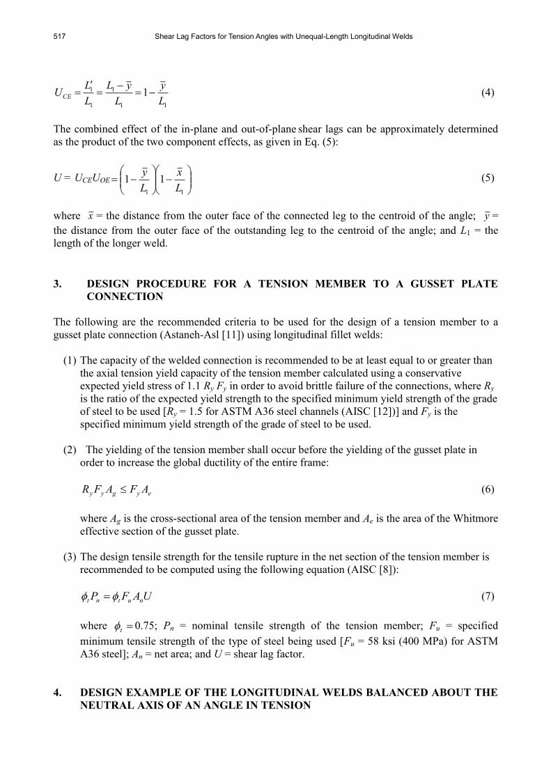
Referring to the tension member shown in Figure 1, when the tension load is transmitted to some,
but not all of the cross-sectional elements, the effective length of the welded connection is reduced
to L' = L - x , where x is the connection eccentricity measured from the plane of the connection to

515 Shear Lag Factors for Tension Angles with Unequal-Length Longitudinal Welds
the member centroid and L is the length of the connection in the direction of loading. Since the
reduction in the effective cross-sectional area is proportional to the reduction in the effective
connection length, L' / L, the out-of-plane shear lag factor becomes (Geschwindner [9]):
L
x
L
xL
L
LUOE
1 (1)
Therefore, the value of the out-of-plane shear lag factor is influenced by the length of the
connection and the geometry of the cross-section of the tension member.
In addition to the out-of-plane shear lag effect for unconnected (outstanding) element(s), the
in-plane shear lag effect, UCE, for connected element(s) was also recommended to be considered, as
given in Eq. (2) (Fortney and Thornton [10]):
2
3
11
1
L
wUCE (2)
where w = the distance between longitudinal welds and L = the length of weld.
45°
xL
xL
L
L'
Figure 1. Out-of-Plane Shear Lag Effect on Welded Angle in Tension
(b)
(a)
xL
L
J. K. Hsiao and S. Shrestha 516
The combined effect of the in-plane and out-of-plane shear lags can be approximately determined
as the product of the two component effects as given in Eq. (3) (Fortney and Thornton [10]):
U = UCEUOE
L
x
L
w1
3
11
12
(3)
2. NEWLY PROPOSED PROCEDURE FOR THE COMPUTATION OF SHEAR LAG
FACTORS
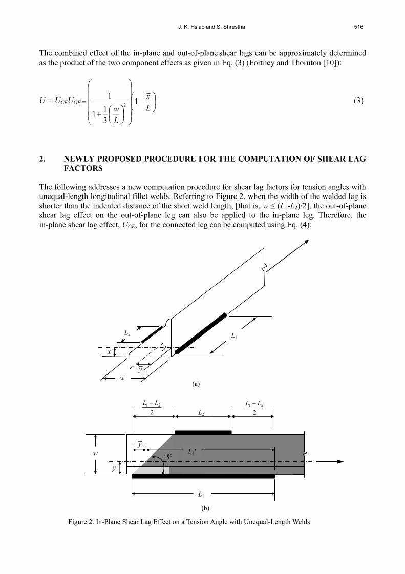
The following addresses a new computation procedure for shear lag factors for tension angles with
unequal-length longitudinal fillet welds. Referring to Figure 2, when the width of the welded leg is
shorter than the indented distance of the short weld length, [that is, w ≤ (L1-L2)/2], the out-of-plane
shear lag effect on the out-of-plane leg can also be applied to the in-plane leg. Therefore, the
in-plane shear lag effect, UCE, for the connected leg can be computed using Eq. (4):
Figure 2. In-Plane Shear Lag Effect on a Tension Angle with Unequal-Length Welds
(b)
2
21 LL
L2 2
21 LL
y
L
45°
y
L L1'
L1
w
y
L (a)
xL
L1 L2
w
517 Shear Lag Factors for Tension Angles with Unequal-Length Longitudinal Welds
11
1
1
1 1L
y
L
yL
L
LUCE
(4)
The combined effect of the in-plane and out-of-plane shear lags can be approximately determined
as the product of the two component effects, as given in Eq. (5):
U = UCEUOE
11
11L
x
L
y (5)
where x = the distance from the outer face of the connected leg to the centroid of the angle; y =
the distance from the outer face of the outstanding leg to the centroid of the angle; and L1 = the
length of the longer weld.
3. DESIGN PROCEDURE FOR A TENSION MEMBER TO A GUSSET PLATE
CONNECTION
The following are the recommended criteria to be used for the design of a tension member to a
gusset plate connection (Astaneh-Asl [11]) using longitudinal fillet welds:
(1) The capacity of the welded connection is recommended to be at least equal to or greater than
the axial tension yield capacity of the tension member calculated using a conservative
expected yield stress of 1.1 Ry Fy in order to avoid brittle failure of the connections, where Ry
is the ratio of the expected yield strength to the specified minimum yield strength of the grade
of steel to be used [Ry = 1.5 for ASTM A36 steel channels (AISC [12])] and Fy is the
specified minimum yield strength of the grade of steel to be used.
(2) The yielding of the tension member shall occur before the yielding of the gusset plate in
order to increase the global ductility of the entire frame:
eygyy AFAFR (6)
where Ag is the cross-sectional area of the tension member and Ae is the area of the Whitmore
effective section of the gusset plate.
(3) The design tensile strength for the tensile rupture in the net section of the tension member is
recommended to be computed using the following equation (AISC [8]):
UAFP nutnt (7)
where t 0.75; Pn = nominal tensile strength of the tension member; Fu = specified
minimum tensile strength of the type of steel being used [Fu = 58 ksi (400 MPa) for ASTM
A36 steel]; An = net area; and U = shear lag factor.
4. DESIGN EXAMPLE OF THE LONGITUDINAL WELDS BALANCED ABOUT THE
NEUTRAL AXIS OF AN ANGLE IN TENSION

J. K. Hsiao and S. Shrestha 518
Use A36 steel, E70 electrodes to design the longitudinal side fillet welds to develop the full axial
yield capacity of a 2L4×3×⅜ LLBB (with long legs back-to-back) tension member connected to a
gusset plate. Assume that the tension member is subjected to cyclic loading which results in
repeated stress variations; therefore, it is preferable to use two longitudinal welds of unequal length
to ensure the welds’ centroid will coincide with the centroid of the member so that the transmitted
tensile forces will be balanced about the neutral axis of the tension angle (AISC [8]).
4.1 Design of the Unequal-Length Longitudinal Fillet Weld Connection to Balance the
Tensile Forces about the Neutral Axis of the Tension Angle
The full axial yield capacity of a L4×3×⅜ tension member can be computed as follows:
1.1 Ry Fy Ag = 1.1 (1.5)(36 ksi)(2.49 in2) = 147.9 kips (658 kN)
where Ry = 1.5 and Fy = 36 ksi (248 MPa) for A36 steel; Ag = the gross area of the tension member.
Assume that the gusset plate is thicker than the angle. In this case, since the material thickness of
the thinner part joined is ⅜ in. (10 mm), the minimum weld size = 3/16 in. (5 mm) (AISC [8]). Also,
since the thickness of the angle is ⅜ in. (10 mm), the maximum weld size = ⅜ - 1/16 = 5/16 in. (8 mm)
(AISC [13]). With the minimum and maximum fillet weld sizes defined, one can use a size of ¼ in.
(6 mm) for the fillet weld (since 3/16 ≤ ¼ ≤ 5/16, the weld size may be used). The design strength of
the weld per inch can thus be computed as follows:
ϕ te (0.60 FEXX) = 0.75 [(0.707) (¼ in.)](0.60)(70 ksi) = 5.568 kips/in. (0.975 kN/mm)
where te = the effective throat of the fillet weld and FEXX = the tensile strength of the weld metal
(FEXX =70 ksi for E70 electrodes).
Therefore, the total required weld length can be computed as follows:
Ltotal = kips/in.568.5
kips9.147 = 26.56 in. (675 mm)
Referring to Figure 3(a), taking the moment about point A to determine the force P2 and P1:
P2 (4 in.) = (147.9 kips) (1.27 in.)
From which,
4
27.19.1472 P = 47.0 kips (209 kN), and 1P =147.9 - 47.0 =100.9 kips (449 kN)
Therefore, the required weld length on the outstanding leg side, L1, and on the flat leg side, L2, can
be computed respectively as follows:
12.18568.5
9.1001 L in. ≈ 18.5 in. (470 mm)
44.8568.5
0.472 L in. ≈ 8.5 in. (216 mm)
519 Shear Lag Factors for Tension Angles with Unequal-Length Longitudinal Welds
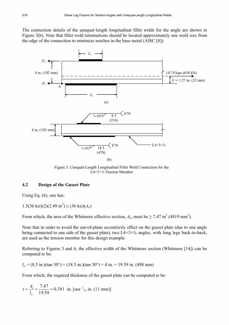
The connection details of the unequal-length longitudinal fillet welds for the angle are shown in
Figure 3(b). Note that fillet weld terminations should be located approximately one weld size from
the edge of the connection to minimize notches in the base metal (AISC [8]).
4.2 Design of the Gusset Plate
Using Eq. (6), one has:
1.5(36 ksi)(2)(2.49 in2) ≤ (36 ksi)(Ae)
From which, the area of the Whitmore effective section, Ae, must be ≥ 7.47 in2 (4819 mm
2).
Note that in order to avoid the out-of-plane eccentricity effect on the gusset plate (due to one angle
being connected to one side of the gusset plate), two L4×3×⅜ angles, with long legs back-to-back,
are used as the tension member for this design example.
Referring to Figures 3 and 4, the effective width of the Whitmore section (Whitmore [14]) can be
computed to be:
lw = (8.5 in.)(tan 30°) + (18.5 in.)(tan 30°) + 4 in. = 19.59 in. (498 mm)
From which, the required thickness of the gusset plate can be computed to be:
381.059.19
47.7
w
e
l
At in. [use 7
/16 in. (11 mm)]
4 in. (102 mm)
¼ (6) E70
E70 8.5
(216)
A P1
P2
147.9 kips (658 kN)
y 1.27 in. (32 mm)
Figure 3. Unequal-Length Longitudinal Fillet Weld Connection for the
L4×3×⅜ Tension Member
(b)
(a)
L1
L2
4 in. (102 mm)
¼ (6)
18.5
(470)
L4×3×⅜

J. K. Hsiao and S. Shrestha 520
LLBB Double
Angles
y
in.
(mm)
b
in.
(mm)
t
in.
(mm)
a
in.
(mm)
l1
in.
(mm)
l2
in.
(mm)
2L4×3×3/8 1.27
(32)
6
(152)
7/16
(11)
¼
(6) 18.5
(470)
8.5
(216)
2L6×3½×3/8 2.02
(51)
8
(203)
7/16
(11)
¼
(6) 24.5
(622)
12.5
(318)
2L6×4×9/16 2
(51)
8
(203)
⅝ (16)
⅜ (10)
25.5
(648)
13
(330)
30°
30°
lw
Welded joint
Figure 4. The Whitmore Section for Unequal-Length Welded Joints
Figure 5. Unequal-Length Longitudinal Fillet Weld Connection Details for Double Angles
Near side
& far side l2 a
l1 a
Neutral axis
b/2 a
y
/2
a
b
45°
30°
2 t
b/2
LLBB double angles
Near side & far side
Notes: t = Plate thickness; a = Weld size; l1 = Long weld length; and l2 = Short weld length
521 Shear Lag Factors for Tension Angles with Unequal-Length Longitudinal Welds
Following the procedure of this design example, the unequal-length longitudinal fillet weld
connections for two additional double angles of different sizes (2L6×3½×3/8 and 2L6×4×
9/16) are
designed and summarized in Figure 5. Note that in order to ensure that the gusset plate can freely
rotate when the double angles are subjected to compression forces, the distance from the end of the
double angles to the line that connects the two re-entrant corners of the gusset plate is at least two
times the thickness of the gusset plate (Astaneh-Asl [11]).
5. COMPUTATION OF SHEAR LAG FACTORS FOR TENSION ANGLES WITH
UNEQUAL-LENGTH LONGITUDINAL FILLET WELD CONNECTIONS
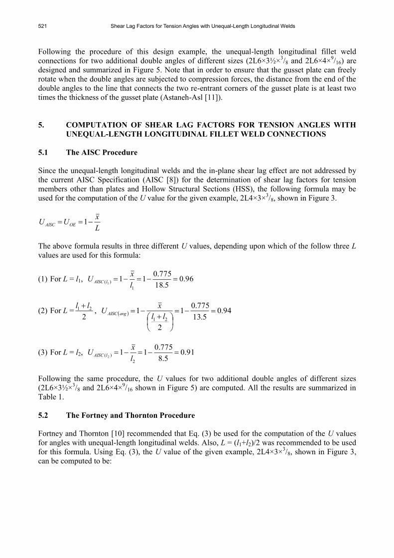
5.1 The AISC Procedure
Since the unequal-length longitudinal welds and the in-plane shear lag effect are not addressed by
the current AISC Specification (AISC [8]) for the determination of shear lag factors for tension
members other than plates and Hollow Structural Sections (HSS), the following formula may be
used for the computation of the U value for the given example, 2L4×3×3/8, shown in Figure 3.
L
xUU OEAISC 1
The above formula results in three different U values, depending upon which of the follow three L
values are used for this formula:
(1) For L = l1, 96.05.18
775.011
1
)( 1
l
xU lAISC
(2) For L =2
21 ll , 94.0
5.13
775.01
2
121
ll
xU avgAISC
(3) For L = l2, 91.05.8
775.011
2
)( 2
l
xU lAISC
Following the same procedure, the U values for two additional double angles of different sizes
(2L6×3½×3/8 and 2L6×4×
9/16 shown in Figure 5) are computed. All the results are summarized in
Table 1.
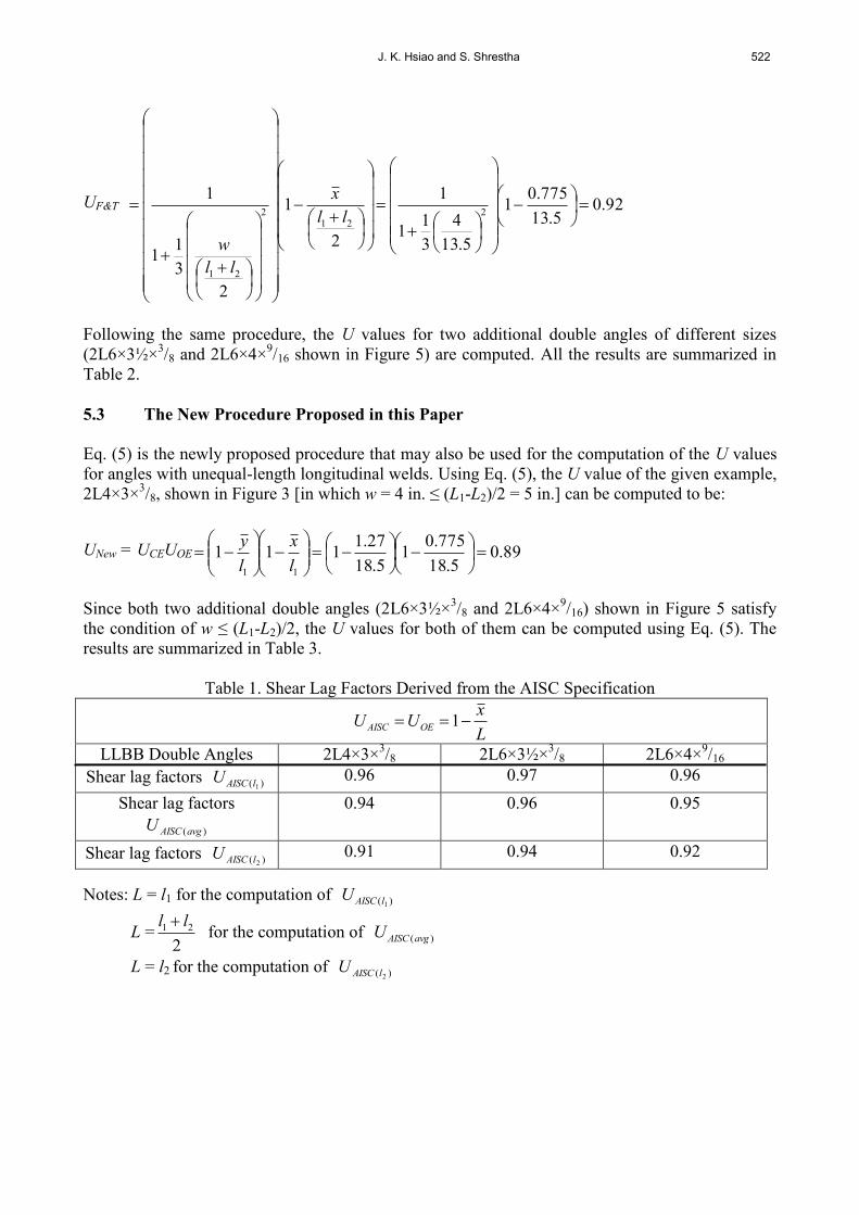
5.2 The Fortney and Thornton Procedure
Fortney and Thornton [10] recommended that Eq. (3) be used for the computation of the U values
for angles with unequal-length longitudinal welds. Also, L = (l1+l2)/2 was recommended to be used
for this formula. Using Eq. (3), the U value of the given example, 2L4×3×3/8, shown in Figure 3,
can be computed to be:
J. K. Hsiao and S. Shrestha 522
UF&T 92.05.13
775.01
5.13
4
3
11
1
2
1
2
3
11
12
212
21
ll
x
ll
w
Following the same procedure, the U values for two additional double angles of different sizes
(2L6×3½×3/8 and 2L6×4×
9/16 shown in Figure 5) are computed. All the results are summarized in
Table 2.
5.3 The New Procedure Proposed in this Paper
Eq. (5) is the newly proposed procedure that may also be used for the computation of the U values
for angles with unequal-length longitudinal welds. Using Eq. (5), the U value of the given example,
2L4×3×3/8, shown in Figure 3 [in which w = 4 in. ≤ (L1-L2)/2 = 5 in.] can be computed to be:
UNew = UCEUOE 89.05.18
775.01
5.18
27.1111
11
l
x
l
y
Since both two additional double angles (2L6×3½×3/8 and 2L6×4×
9/16) shown in Figure 5 satisfy
the condition of w ≤ (L1-L2)/2, the U values for both of them can be computed using Eq. (5). The
results are summarized in Table 3.
Table 1. Shear Lag Factors Derived from the AISC Specification
L
xUU OEAISC 1
LLBB Double Angles 2L4×3×3/8 2L6×3½×
3/8 2L6×4×
9/16
Shear lag factors )( 1lAISCU 0.96 0.97 0.96
Shear lag factors
)(avgAISCU
0.94 0.96 0.95
Shear lag factors )( 2lAISCU 0.91 0.94 0.92
Notes: L = l1 for the computation of )( 1lAISCU
L =2
21 ll for the computation of )(avgAISCU
L = l2 for the computation of )( 2lAISCU
523 Shear Lag Factors for Tension Angles with Unequal-Length Longitudinal Welds
Table 2. Shear Lag Factors Derived from Fortney and Thornton
UF&T = UCEUOE
L
x
L
w1
3
11
12
LLBB Double
Angles
2L4×3×3/8 2L6×3½×
3/8 2L6×4×
9/16
Shear lag factors UF&T 0.92 0.93 0.92
Note: L =2
21 ll for the computation of UF&T
Table 3. Shear Lag Factors Derived from the Newly Proposed Formula
UNew = UCEUOE
11
11l
x
l
y
LLBB Double Angles 2L4×3×3/8 2L6×3½×
3/8 2L6×4×
9/16
Shear lag factors UNew 0.89 0.89 0.89
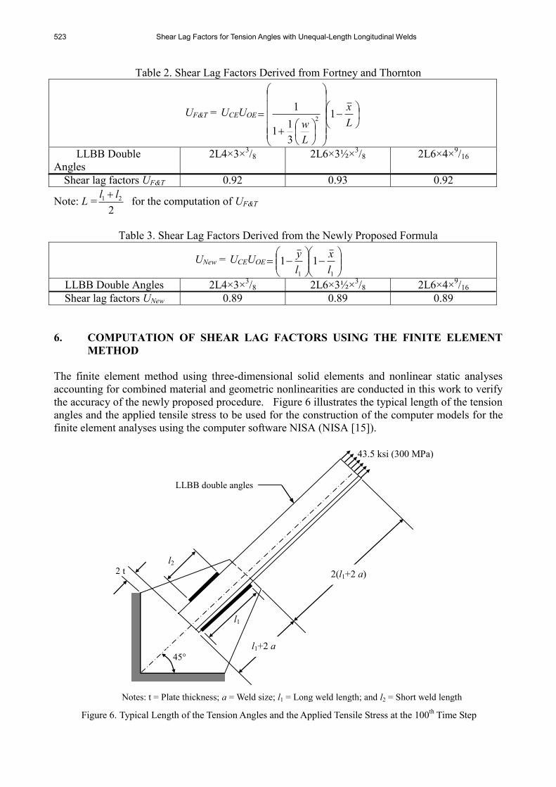
6. COMPUTATION OF SHEAR LAG FACTORS USING THE FINITE ELEMENT
METHOD
The finite element method using three-dimensional solid elements and nonlinear static analyses
accounting for combined material and geometric nonlinearities are conducted in this work to verify
the accuracy of the newly proposed procedure. Figure 6 illustrates the typical length of the tension
angles and the applied tensile stress to be used for the construction of the computer models for the
finite element analyses using the computer software NISA (NISA [15]).
Figure 6. Typical Length of the Tension Angles and the Applied Tensile Stress at the 100
th Time Step
2 t
Notes: t = Plate thickness; a = Weld size; l1 = Long weld length; and l2 = Short weld length
LLBB double angles
l2
l1
43.5 ksi (300 MPa)
l1+2 a
2(l1+2 a)
45°
J. K. Hsiao and S. Shrestha 524
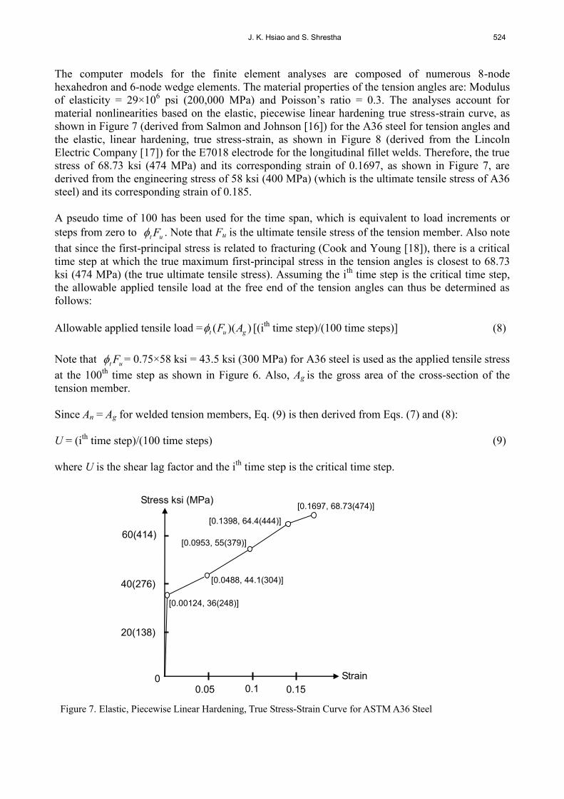
The computer models for the finite element analyses are composed of numerous 8-node
hexahedron and 6-node wedge elements. The material properties of the tension angles are: Modulus
of elasticity = 29×106 psi (200,000 MPa) and Poisson’s ratio = 0.3. The analyses account for
material nonlinearities based on the elastic, piecewise linear hardening true stress-strain curve, as
shown in Figure 7 (derived from Salmon and Johnson [16]) for the A36 steel for tension angles and
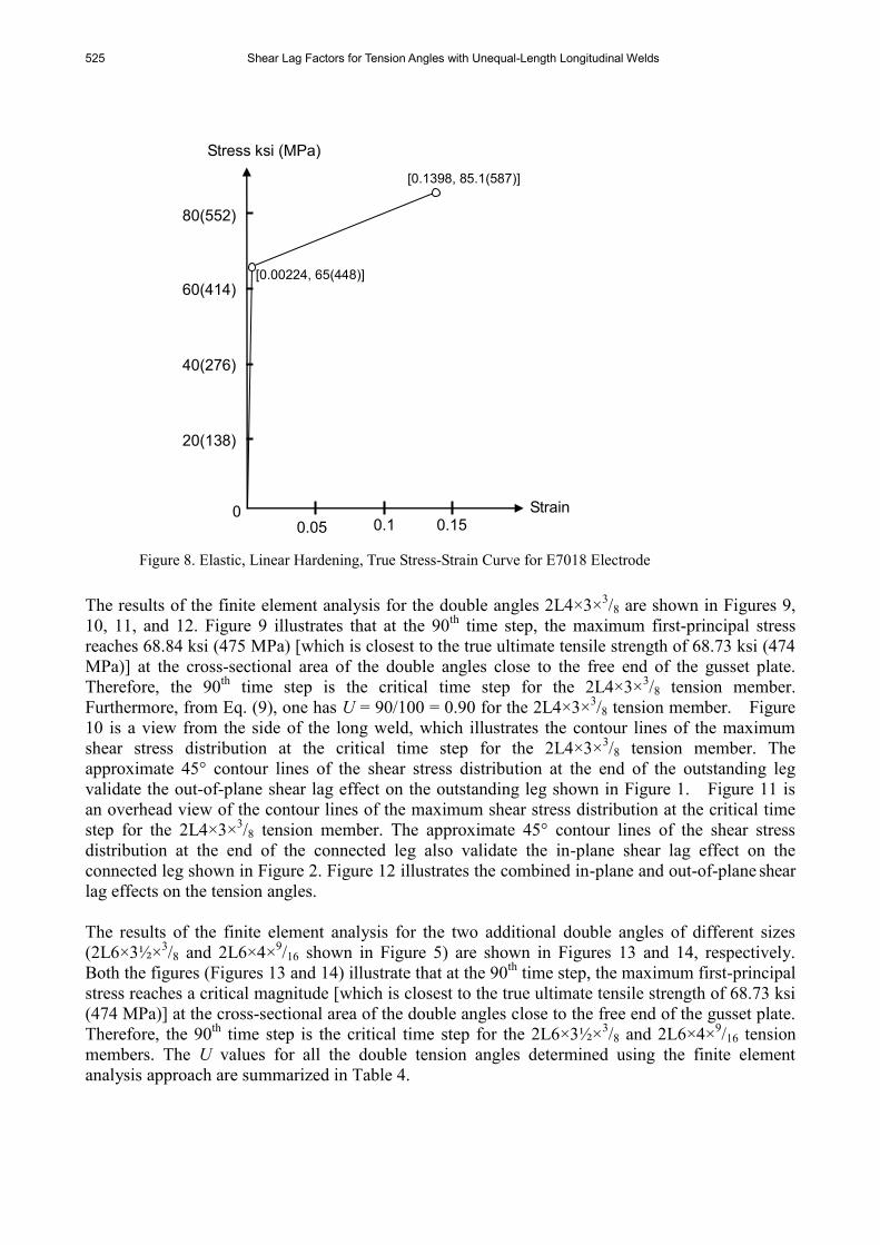
the elastic, linear hardening, true stress-strain, as shown in Figure 8 (derived from the Lincoln
Electric Company [17]) for the E7018 electrode for the longitudinal fillet welds. Therefore, the true
stress of 68.73 ksi (474 MPa) and its corresponding strain of 0.1697, as shown in Figure 7, are
derived from the engineering stress of 58 ksi (400 MPa) (which is the ultimate tensile stress of A36
steel) and its corresponding strain of 0.185.
A pseudo time of 100 has been used for the time span, which is equivalent to load increments or
steps from zero to ut F . Note that Fu is the ultimate tensile stress of the tension member. Also note
that since the first-principal stress is related to fracturing (Cook and Young [18]), there is a critical
time step at which the true maximum first-principal stress in the tension angles is closest to 68.73
ksi (474 MPa) (the true ultimate tensile stress). Assuming the ith
time step is the critical time step,
the allowable applied tensile load at the free end of the tension angles can thus be determined as
follows:
Allowable applied tensile load = ))(( gut AF [(ith
time step)/(100 time steps)] (8)
Note that ut F = 0.75×58 ksi = 43.5 ksi (300 MPa) for A36 steel is used as the applied tensile stress
at the 100th
time step as shown in Figure 6. Also, Ag is the gross area of the cross-section of the
tension member.
Since An = Ag for welded tension members, Eq. (9) is then derived from Eqs. (7) and (8):
U = (ith
time step)/(100 time steps) (9)
where U is the shear lag factor and the ith
time step is the critical time step.
40(276)
Strain
60(414)
20(138)
0
Stress ksi (MPa)
0.05 0.1 0.15
[0.00124, 36(248)]
[0.0488, 44.1(304)]
[0.0953, 55(379)]
[0.1398, 64.4(444)]
[0.1697, 68.73(474)]
Figure 7. Elastic, Piecewise Linear Hardening, True Stress-Strain Curve for ASTM A36 Steel
525 Shear Lag Factors for Tension Angles with Unequal-Length Longitudinal Welds
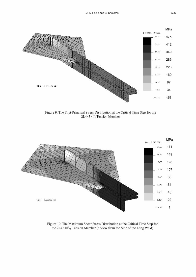
The results of the finite element analysis for the double angles 2L4×3×3/8 are shown in Figures 9,
10, 11, and 12. Figure 9 illustrates that at the 90th
time step, the maximum first-principal stress
reaches 68.84 ksi (475 MPa) [which is closest to the true ultimate tensile strength of 68.73 ksi (474
MPa)] at the cross-sectional area of the double angles close to the free end of the gusset plate.
Therefore, the 90th
time step is the critical time step for the 2L4×3×3/8 tension member.
Furthermore, from Eq. (9), one has U = 90/100 = 0.90 for the 2L4×3×3/8 tension member. Figure
10 is a view from the side of the long weld, which illustrates the contour lines of the maximum
shear stress distribution at the critical time step for the 2L4×3×3/8 tension member. The
approximate 45° contour lines of the shear stress distribution at the end of the outstanding leg
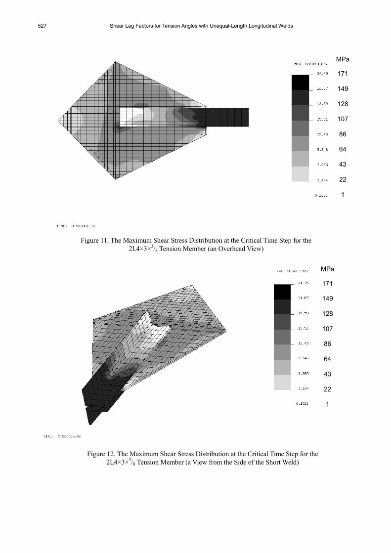
validate the out-of-plane shear lag effect on the outstanding leg shown in Figure 1. Figure 11 is
an overhead view of the contour lines of the maximum shear stress distribution at the critical time
step for the 2L4×3×3/8 tension member. The approximate 45° contour lines of the shear stress
distribution at the end of the connected leg also validate the in-plane shear lag effect on the
connected leg shown in Figure 2. Figure 12 illustrates the combined in-plane and out-of-plane shear
lag effects on the tension angles.
The results of the finite element analysis for the two additional double angles of different sizes
(2L6×3½×3/8 and 2L6×4×
9/16 shown in Figure 5) are shown in Figures 13 and 14, respectively.
Both the figures (Figures 13 and 14) illustrate that at the 90th
time step, the maximum first-principal
stress reaches a critical magnitude [which is closest to the true ultimate tensile strength of 68.73 ksi
(474 MPa)] at the cross-sectional area of the double angles close to the free end of the gusset plate.
Therefore, the 90th
time step is the critical time step for the 2L6×3½×3/8 and 2L6×4×
9/16 tension
members. The U values for all the double tension angles determined using the finite element
analysis approach are summarized in Table 4.
Stress ksi (MPa)
80(552)
Strain
40(276)
60(414)
20(138)
0 0.05 0.1 0.15
[0.00224, 65(448)]
[0.1398, 85.1(587)]
Figure 8. Elastic, Linear Hardening, True Stress-Strain Curve for E7018 Electrode
J. K. Hsiao and S. Shrestha 526
Figure 9. The First-Principal Stress Distribution at the Critical Time Step for the
2L4×3×3/8 Tension Member
Figure 10. The Maximum Shear Stress Distribution at the Critical Time Step for
the 2L4×3×3/8 Tension Member (a View from the Side of the Long Weld)
MPa
171
149
128
107
86
64
43
22 1
MPa
475
412
349
286
223
160
97
34
-29
527 Shear Lag Factors for Tension Angles with Unequal-Length Longitudinal Welds
Figure 11. The Maximum Shear Stress Distribution at the Critical Time Step for the
2L4×3×3/8 Tension Member (an Overhead View)
Figure 12. The Maximum Shear Stress Distribution at the Critical Time Step for the
2L4×3×3/8 Tension Member (a View from the Side of the Short Weld)
MPa
171
149
128
107
86
64
43
22 1
MPa
171
149
128
107
86
64
43
22 1

J. K. Hsiao and S. Shrestha 528
Figure 13. The First-Principal Stress Distribution at the Critical Time Step for the
2L6×3½×3/8 Tension Member
MPa
473
424
374
324
274
223
173
123
73
23
-28
Figure 14. The First-Principal Stress Distribution at the Critical Time Step for the
2L6×4×9/16 Tension Member
MPa
474
438
387
335
283
231
179
128
76
24
-28
529 Shear Lag Factors for Tension Angles with Unequal-Length Longitudinal Welds
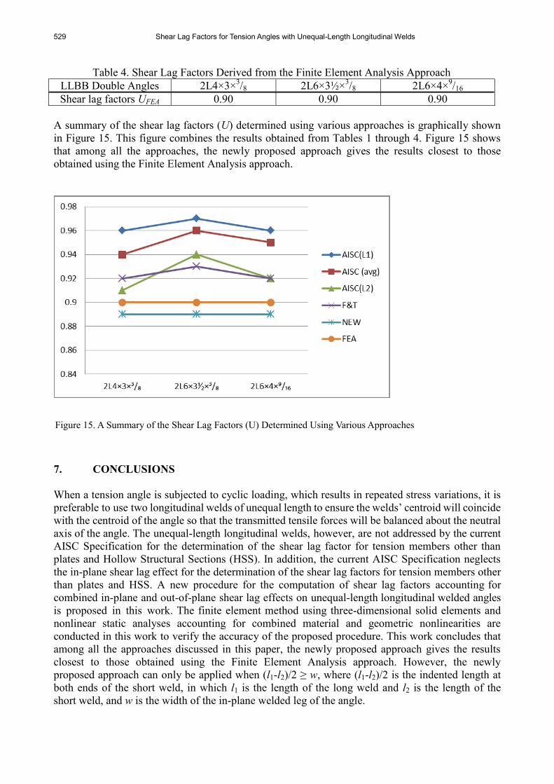
Table 4. Shear Lag Factors Derived from the Finite Element Analysis Approach
LLBB Double Angles 2L4×3×3/8 2L6×3½×
3/8 2L6×4×
9/16
Shear lag factors UFEA 0.90 0.90 0.90
A summary of the shear lag factors (U) determined using various approaches is graphically shown
in Figure 15. This figure combines the results obtained from Tables 1 through 4. Figure 15 shows
that among all the approaches, the newly proposed approach gives the results closest to those
obtained using the Finite Element Analysis approach.
7. CONCLUSIONS
When a tension angle is subjected to cyclic loading, which results in repeated stress variations, it is
preferable to use two longitudinal welds of unequal length to ensure the welds’ centroid will coincide
with the centroid of the angle so that the transmitted tensile forces will be balanced about the neutral
axis of the angle. The unequal-length longitudinal welds, however, are not addressed by the current
AISC Specification for the determination of the shear lag factor for tension members other than
plates and Hollow Structural Sections (HSS). In addition, the current AISC Specification neglects
the in-plane shear lag effect for the determination of the shear lag factors for tension members other
than plates and HSS. A new procedure for the computation of shear lag factors accounting for
combined in-plane and out-of-plane shear lag effects on unequal-length longitudinal welded angles
is proposed in this work. The finite element method using three-dimensional solid elements and
nonlinear static analyses accounting for combined material and geometric nonlinearities are
conducted in this work to verify the accuracy of the proposed procedure. This work concludes that
among all the approaches discussed in this paper, the newly proposed approach gives the results
closest to those obtained using the Finite Element Analysis approach. However, the newly
proposed approach can only be applied when (l1-l2)/2 ≥ w, where (l1-l2)/2 is the indented length at
both ends of the short weld, in which l1 is the length of the long weld and l2 is the length of the
short weld, and w is the width of the in-plane welded leg of the angle.
Figure 15. A Summary of the Shear Lag Factors (U) Determined Using Various Approaches

J. K. Hsiao and S. Shrestha 530
REFERENCES
[1] Easterling, W.S. and Gonzalez Giroux, L., “Shear Lag Effects in Steel Tension Members”,
Engineering Journal, American Institute of Steel Construction, 3rd
Quarter, 1993, Vol. 30, pp.
77-89.
[2] AISC, “Specification for the Design, Fabrication and Erection of Structural Steel for
Buildings”, American Institute of Steel Construction, Inc., Chicago, IL., 1978.
[3] AISC, “Specification for Structural Steel Buildings-Load and Resistance Factor Design”,
American Institute of Steel Construction, Inc., Chicago, IL., 1986.
[4] AISC, “Specification for Structural Steel Buildings-Allowable Stress Design and Plastic
Design”, American Institute of Steel Construction, Inc., Chicago, IL., 1989.
[5] AISC, “LRFD Specification for Structural Steel Buildings”, American Institute of Steel
Construction, Inc., Chicago, IL., 1993.
[6] AISC, “LRFD Specification for Structural Steel Buildings”, American Institute of Steel
Construction, Inc., Chicago, IL., 1999.
[7] AISC, “Specification for Structural Steel Buildings”, American Institute of Steel
Construction, Inc., Chicago, IL., 2005.
[8] AISC, “Specification for Structural Steel Buildings”, American Institute of Steel
Construction, Inc., Chicago, IL., 2010.
[9] Geschwindner, L.F., “Unified Design of Steel Structures”, John Wiley & Sons, Inc., Upper
Hoboken, N.J., 2008.
[10] Fortney, P.J. and Thornton, W.A., “Recommendations for Shear Lag Factors for
Longitudinally-Welded Tension Members”, Engineering Journal, American Institute of Steel
Construction, 1st Quarter, 2012, pp. 11-32.
[11] Astaneh-Asl, A., “Seismic Behavior and Design of Gusset Plates,” Steel Tips Report,
Structural Steel Educational Council, Moraga, CA., 1998.
[12] AISC, “Seismic Provisions for Structural Steel Buildings”, American Institute of Steel
Construction, Inc., Chicago, IL., 2005.
[13] AISC, “Steel Construction Manual”, 14th
Edition, American Institute of Steel Construction,
Inc., Chicago, IL., 2011.
[14] Whitmore, R.E., “Experimental Investigation of Stresses in Gusset Plates”, Bulletin No. 16,
Engineering Experiment Station, Univ. of Tennessee, TN., 1952.
[15] NISA, “NISA User’s Manual”, the Cranes Software, Inc., Troy, MI, 2005.
[16] Salmon, C.G., Johnson, J.E. and Malhas F.A., “Steel Structures, Design and Behavior”, 5th
Ed., Pearson Prentice Hall, Upper Saddle River, N.J., 2009.
[17] The Lincoln Electric Company, “The Procedure Handbook of Arc Welding”, 13th
Ed., The
Lincoln Electric Company, Cleveland, OH., 1994.
[18] Cook, R.D. and Young, W.C., “Advanced Mechanics of Materials”, Macmillan Publishing
Company, New York, N.Y., 1985.