Embed Size (px)
Citation preview
Vol.:(0123456789)1 3
International Journal of Advanced Structural Engineering (2019) 11:377–384 https://doi.org/10.1007/s40091-019-00239-5
ORIGINAL RESEARCH
Shear buckling behavior of a plate composite girder using concrete‑filled steel tube structures
Jun‑Gi Sim1
Received: 6 September 2018 / Accepted: 13 August 2019 / Published online: 26 August 2019 © The Author(s) 2019
AbstractIn this study, the shear buckling behavior of plate girders using concrete-filled steel tube structure was verified by nonlinear finite element analysis using CEB-FIP 1990 code. In addition, shear buckling tests were carried out on the model specimens and compared with the analysis. As a result, it was confirmed that the proposed plate girder improved the shear buckling resistance compared to the general plate girder. Also, by comparing the test results with the analysis, we propose that the proposed CEP-FIP code is a reasonable analysis. Particularly, as a result of comparing the maximum deflection displace-ment of the plate girder, it was found that the proposed girder improved the shear buckling resistance performance due to the confinement effect of the concrete-filled steel tube structure than general plate girder.
Keywords Shear buckling · Plate composite girder · Concrete-filled steel tube · Mock-up test · Finite element analysis
Introduction
The I-shaped plate girder is widely used as a flexural mem-ber, because its section rigidity is efficient. However, in the case of such a general plate girder, there is a problem of shear buckling, and therefore research has been carried out to overcome this problem.
Lee et al. (1996) studied the shear buckling of plate girders by boundary condition by finite element modeling to confirm the shear buckling behavior of plate girders. Höglund (1997) studied the shear buckling resistance of plate girders using steel and aluminum materials. Lee and Yoo (1998) performed a finite element nonlinear analysis of the shear buckling strength of plate girders for pure shear force. Baskar et al. (2002) performed a finite element non-linear analysis on the moment and shear loads of steel–con-crete composite plate girder. At this time, in Japan, Naka-mura et al. (2002) studied a girder utilizing a concrete-filled steel tube structure. Wu et al. (2006) studied the application of concrete-filled steel tube structures to the ribs of arch bridges for earthquakes. Bambach et al. (2008) conducted
a comparative study of the lateral load impacts of sections using concrete-filled steel tube structures and general hollow sections. Okamoto et al. (2012) studied girder-type girders reinforced with arch ribs of concrete-filled steel tube struc-tures. Sim (2017) has been working on reinforcing the upper and lower flanges with a concrete-filled steel tube structure on the plate girder. Chen et al. (2018) studied shear buckling behavior for stainless steel plate girders. At this time, studies were performed on improving the shear buckling resistance of the plate girders using corrugated steel sheets (Darmawan et al. 2018). To improve the shear buckling resistance of the plate girder up to now, a method of controlling the com-pression flange thickness by studying the shear buckling behavior of each material boundary condition was used. In addition, a method of improving shear buckling resistance using a corrugated steel sheet was utilized. However, in the case of conventional plate girders, research to improve the shear buckling resistance by the thickness of the compres-sion flange is dominant. In addition, no studies have been conducted to improve the shear buckling resistance of plate girders using concrete-filled steel tube structures as a new method. Therefore, in this study, I propose the utilization of the concrete-filled steel tube structure which is widely used now as a new method other than the existing method of adjusting the compression flange thickness to improve the shear buckling resistance of the plate girder.
* Jun-Gi Sim [email protected]
1 Structural Engineering Research Division, Korea Bridge Institute Co., Ltd, Bucheon-Si, Gyeonggi-do 14548, Republic of Korea
378 International Journal of Advanced Structural Engineering (2019) 11:377–384
1 3
Shear buckling test of the proposed girder
Basic concept of shear buckling test body
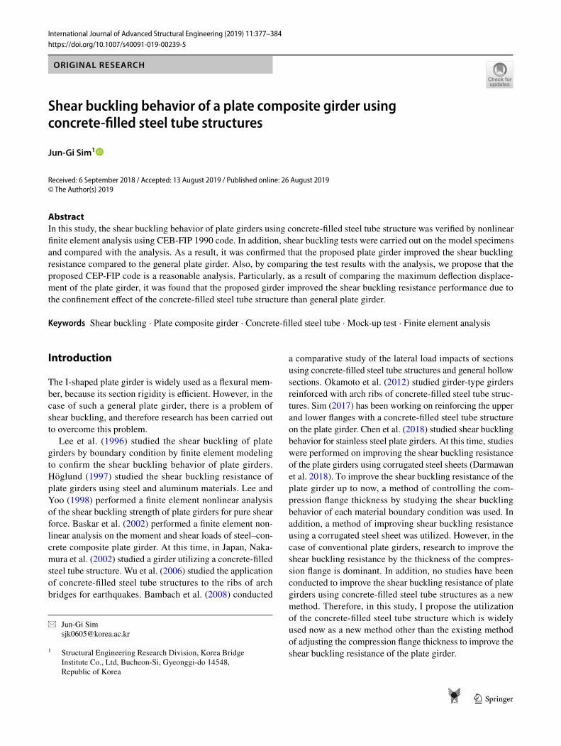
For general plate girders, it is recommended that the com-pression flange thickness should be at least 1.1 times the thickness of the web plate in accordance with the equation (6.10.2.2-3) in 6.10.2.2-Flange proportions of the AASHTO LRFD bridge design specifications (Specifications 2012). As shown in Fig. 1, specimens of the concrete-filled steel tube structure and a cross-section of the normal plate were manufactured with the same stiffness of the compression flange portion.
In the plate girder using concrete-filled steel tube struc-ture, b′
fc is the width of the upper flange, t′
fc is the thickness
of the upper flange, and h is the height of the filled concrete. b is the width of the filled concrete, and t′
w is the thickness
of the web plate abutting the upper flange. In a typical plate girder, tfc is the thickness of the upper flange abutting the web plate, D is the abutting height of the lower flange, tw is the thickness of the web plate, bft is the width of the lower flange, tft is the thickness of the lower flange, D′ is the dis-tance from the neutral axis to the center of the upper flange of the concrete-filled steel tube, and bfc is the upper flange width.
Shear buckling test specification and test method
Detailed specifications of the shear buckling specimen are shown in Table 1. Based on the basic concept of cross-sec-tion, it was constructed so that the compressive portion of
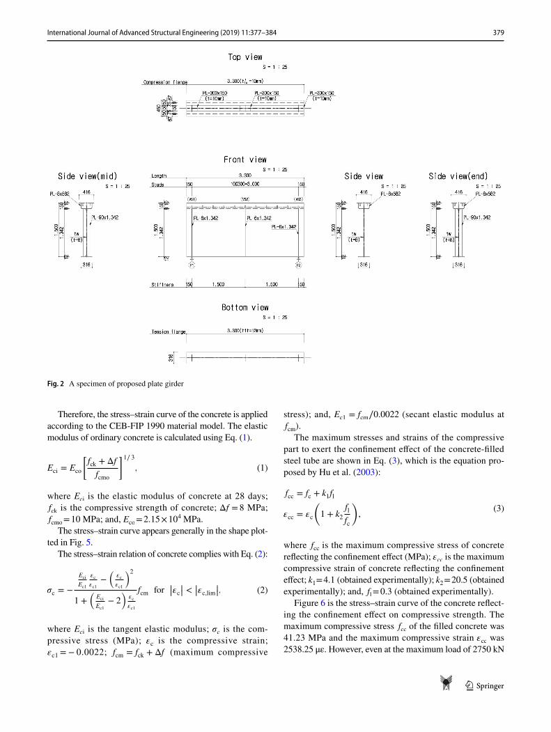
the concrete-filled steel tube structure from the center of the entire cross-section and the center of the compression flange of the general plate coincide with each other. The concrete used was C40 with a compressive strength of 40 MPa, and the steel was HSB500 with an allowable stress of 230 MPa. The shear buckling test is shown in Figs. 2 and 3, the total span length L was 3.3 m and the span was 3.0 m. The bound-ary condition was a roller hinge and was carried out at three points until shear buckling occurred at the mid-point of the specimen with a maximum capacity of 5000 kN.
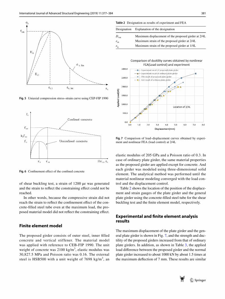
Figure 4 shows the three-point load test for each speci-men, and each specimen was positioned at a distance of 1.5 m from the specimen.
To find the maximum vertical displacement, the displace-ment meter was installed with a vertical direction displace-ment meter at 2/4L of the lower flange and the displace-ment was measured. Also, strain rate was measured at 2/4L of lower flange bottom and 1/4L of lower flange bottom to determine shear buckling point.
Theoretical background for finite element analysis
Since the concrete-filled steel tube structure is applied to improve the shear buckling resistance of the plate girder, the structural behavior of the proposed plate girder should be tested for the ultimate load where buckling occurs. For this purpose, we propose structural analysis considering mate-rial nonlinear analysis using CEB-FIP 1990 material model (CEB 1993).
(a) (b)
Fig. 1 Definitions of a proposed plate girder and b ordinary plate girder
Table 1 Pure steel sections of proposed plate girder and ordinary plate girder (unit: mm)
Types b′fc
t′fc
h t′w
bfc tfc D tw bft tft D′ L
Proposed plate girder 150 10 150 8 316 8 1342 8 316 12 1427 3300Ordinary plate girder – – – – 316 45 1405 8 316 12 1427 3300
379International Journal of Advanced Structural Engineering (2019) 11:377–384
1 3
Therefore, the stress–strain curve of the concrete is applied according to the CEB-FIP 1990 material model. The elastic modulus of ordinary concrete is calculated using Eq. (1).
where Eci is the elastic modulus of concrete at 28 days; fck is the compressive strength of concrete; Δf = 8 MPa; fcmo = 10 MPa; and, Eco = 2.15 × 10⁴ MPa.
The stress–strain curve appears generally in the shape plot-ted in Fig. 5.
The stress–strain relation of concrete complies with Eq. (2):
where Eci is the tangent elastic modulus; �c is the com-pressive stress (MPa); �c is the compressive strain; εc1 = − 0.0022; fcm = fck + Δf (maximum compressive
(1)Eci = Eco
[fck + Δf
fcmo
]1∕ 3,
(2)𝜎c = −
Eci
Ec1
𝜀c
𝜀c1
−(
𝜀c
𝜀c1
)2
1 +(
Eci
Ec1
− 2
)𝜀c
𝜀c1
fcm for ||𝜀c|| < ||𝜀c,lim||,
stress); and, Ec1 = fcm∕0.0022 (secant elastic modulus at fcm).
The maximum stresses and strains of the compressive part to exert the confinement effect of the concrete-filled steel tube are shown in Eq. (3), which is the equation pro-posed by Hu et al. (2003):
where fcc is the maximum compressive stress of concrete reflecting the confinement effect (MPa); �cc is the maximum compressive strain of concrete reflecting the confinement effect; k1 = 4.1 (obtained experimentally); k2 = 20.5 (obtained experimentally); and, fl = 0.3 (obtained experimentally).
Figure 6 is the stress–strain curve of the concrete reflect-ing the confinement effect on compressive strength. The maximum compressive stress fcc of the filled concrete was 41.23 MPa and the maximum compressive strain �cc was 2538.25 με. However, even at the maximum load of 2750 kN
(3)fcc = fc + k1fl
�cc = �c
(
1 + k2fl
fc
)
,
Fig. 2 A specimen of proposed plate girder
380 International Journal of Advanced Structural Engineering (2019) 11:377–384
1 3
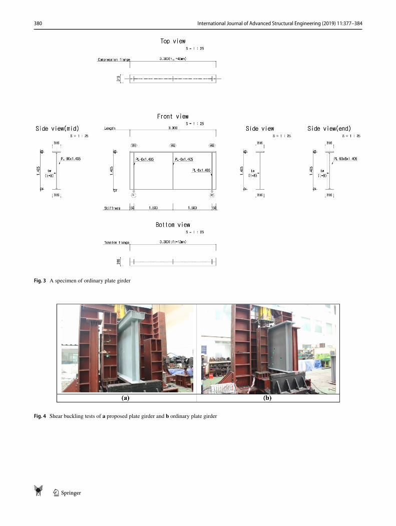
Fig. 3 A specimen of ordinary plate girder
Fig. 4 Shear buckling tests of a proposed plate girder and b ordinary plate girder
381International Journal of Advanced Structural Engineering (2019) 11:377–384
1 3
of shear buckling test, a strain of 1200 με was generated and the strain to reflect the constraining effect could not be reached.
In other words, because the compressive strain did not reach the strain to reflect the confinement effect of the con-crete-filled steel tube even at the maximum load, the pro-posed material model did not reflect the constraining effect.
Finite element model
The proposed girder consists of outer steel, inner filled concrete and vertical stiffener. The material model was applied with reference to CEB-FIP 1990. The unit weight of concrete was 2100 kg/m3, elastic modulus was 30,827.5 MPa and Poisson ratio was 0.16. The external steel is HSB500 with a unit weight of 7698 kg/m3, an
elastic modulus of 205 GPa and a Poisson ratio of 0.3. In case of ordinary plate girder, the same material properties as the proposed girder are applied except for concrete. And each girder was modeled using three-dimensional solid element. The analytical method was performed until the material nonlinear modeling converged with the load con-trol and the displacement control.
Table 2 shows the location of the position of the displace-ment and strain gauges of the plate girder and the general plate girder using the concrete-filled steel tube for the shear buckling test and the finite element model, respectively.
Experimental and finite element analysis results
The maximum displacement of the plate girder and the gen-eral plate girder is shown in Fig. 7, and the strength and duc-tility of the proposed girders increased from that of ordinary plate girders. In addition, as shown in Table 3, the applied load difference between the proposed girder and the normal plate girder increased to about 1000 kN by about 1.5 times at the maximum deflection of 7 mm. These results are similar
Fig. 5 Uniaxial compression stress–strain curve using CEP-FIP 1990
Fig. 6 Confinement effect of the confined concrete
Table 2 Designation as results of experiment and FEA
Designation Explanation of the designation
Dvm Maximum displacement of the proposed girder at 2/4Lεm Maximum strain of the proposed girder at 2/4Lεq Maximum strain of the proposed girder at 1/4L
Fig. 7 Comparison of load–displacement curves obtained by experi-ment and nonlinear FEA (load control) at 2/4L
382 International Journal of Advanced Structural Engineering (2019) 11:377–384
1 3
to the material nonlinear finite element analysis of the load control system. Figure 8 is a comparison of the material nonlinear finite element analysis of the load control method and the experimental results for the relation between the load and the maximum strain at the center portion. As shown in
Table 4, the center maximum strain obtained by the finite element analysis of the load control system is similar to the experimental result up to about 2000 kN with a maximum of 80.1 με. In other words, it is confirmed that the shear buck-ling resistance of the proposed plate girder is improved by the increase in the stiffness and ductility of the girder under the same conditions.
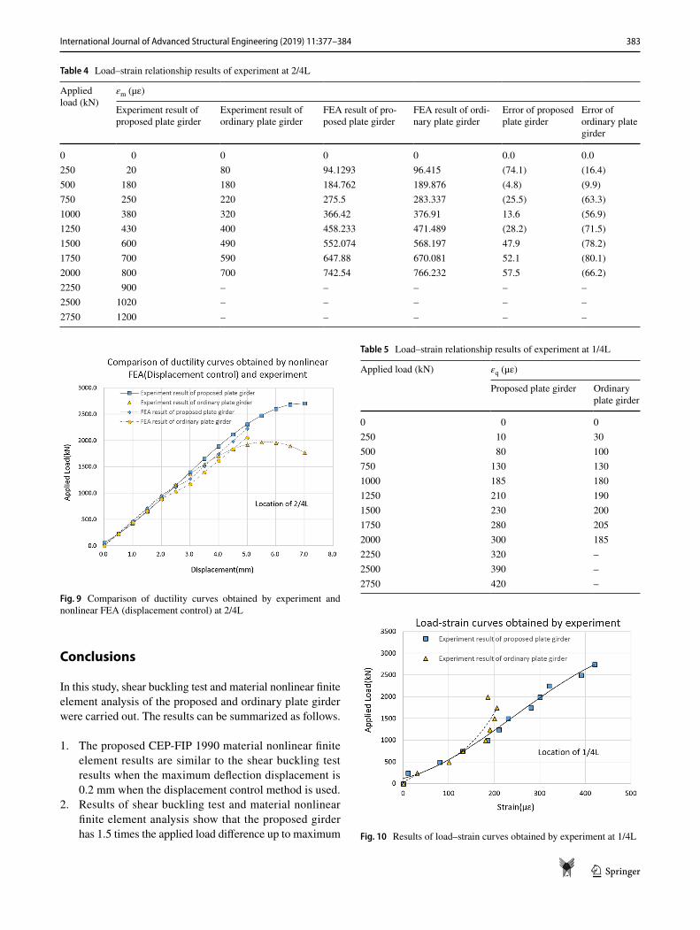
Figure 9 is a comparison of the material nonlinear finite element analysis of the displacement control method and the experimental results for the relation between the load and the maximum deflection at the center. The maximum deflec-tion of the central part obtained by the finite element analy-sis of the displacement control method was similar to the experimental results up to the maximum force of 1750 kN with a maximum difference of 0.2 mm. In other words, it is confirmed that the proposed girder has higher strength and ductility than general plate girder.
As shown in Table 5 and Fig. 10, the strains at the 1/4L span of ordinary plate girder were significantly different from those of the proposed girder at 750 kN. This suggests that horizontal plate buckling of the normal plate girders occurs earlier than the proposed girder, respectively. As shown in Table 6, the deflection profiles for the applied load were similar in comparison of the material nonlinear finite element modeling with the displacement control method.
Table 3 Load–displacement relationship results of experiment and nonlinear FEA (load control) at 2/4L
Dvm (mm) Applied load (kN)
Experiment result of proposed plate girder
Experiment result of ordinary plate girder
FEA result of pro-posed plate girder
FEA result of ordi-nary plate girder
Error of proposed plate girder
Error of ordinary plate girder
0.0 54.5 9.7 0.0 0.0 54.5 9.70.5 224.6 233.9 238.4 220.4 (13.8) 13.51.0 425.8 466.7 476.7 440.8 (50.9) 25.91.5 651.1 702.1 715.1 661.3 (64.0) 40.82.0 893.5 934.1 953.5 881.7 (60.0) 52.42.5 1145.9 1156.9 1112.4 1028.6 33.5 128.33.0 1401.2 1364.5 1271.3 1175.6 129.9 189.03.5 1652.6 1551.0 1509.7 1396.0 142.9 155.14.0 1892.8 1710.5 1748.0 1616.4 144.8 94.14.5 2115.0 1837.0 1986.4 1836.8 128.6 0.25.0 2312.1 1924.6 2224.8 2057.2 87.3 (132.6)5.5 2477.0 1967.4 – – – –6.0 2602.8 1959.4 – – – –6.5 2682.4 1894.7 – – – –7.0 2708.7 1767.3 – – – –
Fig. 8 Comparison of load–strain curves obtained by experiment and nonlinear FEA (load control) at 2/4L
383International Journal of Advanced Structural Engineering (2019) 11:377–384
1 3
Conclusions
In this study, shear buckling test and material nonlinear finite element analysis of the proposed and ordinary plate girder were carried out. The results can be summarized as follows.
1. The proposed CEP-FIP 1990 material nonlinear finite element results are similar to the shear buckling test results when the maximum deflection displacement is 0.2 mm when the displacement control method is used.
2. Results of shear buckling test and material nonlinear finite element analysis show that the proposed girder has 1.5 times the applied load difference up to maximum
Table 4 Load–strain relationship results of experiment at 2/4L
Applied load (kN)
εm (με)
Experiment result of proposed plate girder
Experiment result of ordinary plate girder
FEA result of pro-posed plate girder
FEA result of ordi-nary plate girder
Error of proposed plate girder
Error of ordinary plate girder
0 0 0 0 0 0.0 0.0250 20 80 94.1293 96.415 (74.1) (16.4)500 180 180 184.762 189.876 (4.8) (9.9)750 250 220 275.5 283.337 (25.5) (63.3)1000 380 320 366.42 376.91 13.6 (56.9)1250 430 400 458.233 471.489 (28.2) (71.5)1500 600 490 552.074 568.197 47.9 (78.2)1750 700 590 647.88 670.081 52.1 (80.1)2000 800 700 742.54 766.232 57.5 (66.2)2250 900 – – – – –2500 1020 – – – – –2750 1200 – – – – –
Fig. 9 Comparison of ductility curves obtained by experiment and nonlinear FEA (displacement control) at 2/4L
Table 5 Load–strain relationship results of experiment at 1/4L
Applied load (kN) εq (με)
Proposed plate girder Ordinary plate girder
0 0 0250 10 30500 80 100750 130 1301000 185 1801250 210 1901500 230 2001750 280 2052000 300 1852250 320 –2500 390 –2750 420 –
Fig. 10 Results of load–strain curves obtained by experiment at 1/4L

384 International Journal of Advanced Structural Engineering (2019) 11:377–384
1 3
flexural displacement than the ordinary plate girder. In other words, it is confirmed that the proposed girder exhibits confinement effect of the concrete-filled steel tube structure, so that the strength and ductility are increased as compared with the general plate.
3. As a result of shear buckling comparison test, the strain at the 1/4L span was suddenly generated at the plate girder than the proposed girder at 750kN. That is, through the mock-up experiment, we found that the newly proposed girder improves the shear buckling resistance performance compared to the general plate girder.
Acknowledgements This research was supported by Grants from Korea Bridge Institute Co., Ltd.
Open Access This article is distributed under the terms of the Crea-tive Commons Attribution 4.0 International License (http://creat iveco mmons .org/licen ses/by/4.0/), which permits unrestricted use, distribu-tion, and reproduction in any medium, provided you give appropriate credit to the original author(s) and the source, provide a link to the Creative Commons license, and indicate if changes were made.
References
Bambach MR et al (2008) Hollow and concrete filled steel hollow sections under transverse impact loads. Eng Struct 30(10):2859–2870. https ://doi.org/10.1016/j.engst ruct.2008.04.003
Baskar K et al (2002) Finite-element analysis of steel–concrete com-posite plate girder. J Struct Eng 128(9):1158–1168. https ://doi.org/10.1061/(ASCE)0733-9445(2002)128:9(1158)
CEB (1993) CEB-FIP model code 1990. Thomas Telford, LondonChen XW et al (2018) Shear buckling behaviour of welded stainless
steel plate girders with transverse stiffeners. Thin Walled Struct 122:529–544. https ://doi.org/10.1016/j.tws.2017.10.043
Darmawan AR et al (2018) Perilaku plate girder Badan Bergelombang. Rekayasa Sipil 11(2):116–123. https ://doi.org/10.21776 /ub.rekay asasi pil/2017.011.02.5
Höglund T (1997) Shear buckling resistance of steel and aluminium plate girders. Thin Walled Struct 29(1-4):13–30. https ://doi.org/10.1016/S0263 -8231(97)00012 -8
Hu HT et al (2003) Nonlinear analysis of axially loaded con-crete-filled tube columns with confinement effect. J Struct Eng 129(10):1322–1329. https ://doi.org/10.1061/(ASCE)0733-9445(2003)129:10(1322)
Lee SC, Yoo CH (1998) Strength of plate girder web panels under pure shear. J Struct Eng 124(2):184–194. https ://doi.org/10.1061/(ASCE)0733-9445(1998)124:2(184)
Lee SC et al (1996) Shear buckling coefficients of plate girder web pan-els. Comput Struct 59(5):789–795. https ://doi.org/10.1016/0045-7949(95)00325 -8
Nakamura S et al (2002) New technologies of steel/concrete composite bridges. J Constr Steel Res 58(1):99–130. https ://doi.org/10.1016/S0143 -974X(01)00030 -X
Okamoto Y et al (2012) Study on steel box girder bridges partly stiff-ened by CFT arch ribs. J Constr Steel Res 70:28–35. https ://doi.org/10.1016/j.jcsr.2011.08.012
Sim JG (2017) Evaluation of static structural performance of a plate composite girder using CFT structures. KSCE J Civ Eng 21(4):1424–1433
Specifications (2012) AASHTO specifications. American Association of State Highway and Transportation Officials, Washington, DC
Wu Q, Yoshimura M, Takahashi K, Nakamura S, Nakamura T (2006) Nonlinear seismic properties of the second Saikai bridge: a con-crete filled tubular (CFT) arch bridge. Eng Struct 28(2):163–182. https ://doi.org/10.1016/j.engst ruct.2005.05.003
Publisher’s Note Springer Nature remains neutral with regard to jurisdictional claims in published maps and institutional affiliations.
Table 6 Deformation results of experiment and FEA
Experiment FEA Experiment FEADeformation results of proposed girder Deformation results of ordinary girder
![Author's personal copy - Infosciences personal copy ... Article history: Received 29 July 2010 ... lateral torsional buckling, plate buckling and shear buckling [10 18] .Published](https://img.pdfslide.us/doc/110x75/5afe52147f8b9aa34d8eb790/authors-personal-copy-infoscience-s-personal-copy-article-history-received.jpg)