Embed Size (px)
Citation preview

Journal of Engineering Sciences, Assiut University, Vol. 40, No. 4, pp. 969 -987, July 2012
969
SHEAR BEHAVIOUR OF HIGH STRENGTH FIBER REINFORCED CONCRETE CORBELS
Atif M. Abdel Hafez 1
, Mohamed M. Ahmed 1, Hesham Diab
2
and Ahmed Attia M. Drar 3
1 Associate professor, Civil Engineering Department, Assiut University
2 Lecturer, Civil Engineering Department, Assiut University
3 Demonstrator, Civil Engineering Department, Sohag University
Email: [email protected],
(Received March 21, 2012 Accepted April 15, 2012)
An experimental study of shear behaviour of high strength reinforced-
concrete corbels with and without fibers was investigated. Seventeen high
strength reinforced-concrete corbels were tested. The test variables were
steel fiber content (Vf%), shear span-to-depth ratio (a/d), concrete strength
(fcu), area of main steel reinforcement (Asm) and presence of horizontal
stirrups. Test results showed that, addition of steel fibers or/and horizontal
stirrups improves both shear strength and ductility of the tested corbels, and
results in a more ductile failure mode. Test results were compared with
shear strength predicted using ACI 38-08 equations and those proposed by
other investigators. Comparison between the experimental and the predicted
values of shear strengths showed that the model proposed by G. Campione
et.al. [1], satisfactory predicted the ultimate load for high strength fiber
reinforced-concrete corbels.
KEYWORDS: Fiber reinforced concrete, High-strength concrete, Steel
fibers, Shear behavior, Shear strength, Corbels.
NOTATION
a/d shear span-to-depth ratio fcu cube compressive strength (N/mm2)
Ash area of horizontal stirrups (mm2) Vf % steel fibers content
Asm area of main steel reinforcement (mm2)
1. INTRODUCTION
Corbels are structural members very commonly used in reinforced concrete structures,
particularly in precast structures where their principal function is the transfer of vertical
and horizontal forces to principal members. Corbels are structural members
characterized by a shear span-to-depth ratio (a/d), generally lower than unity and
subjected to concentrated forces as in support zones. For these reasons, they are host
zones of the static and geometric discontinuities and the hypothesis assumed for
members in flexure that sections remain plane after deformation is not valid in this
case. Many studies [1-13] were conducted to determine experimentally and
analytically, the strength of such elements when subjected to vertical and horizontal
forces, and explained the role of the parameters that influence the performance of
corbels, including their shape and dimensions, the type of longitudinal and transverse
steel reinforcements, and the strength of concrete.
Atif M. Abdel Hafez , Mohamed M. Ahmed , Hesham Diab …
970
Recently, high strength concrete has been increasing used in practice. But
high-strength concrete is considered to be a relatively brittle material and has low
ductility. In this investigation, the main goal was using steel fibers to convert the brittle
characteristic to a ductile one, increases the strength and improves the ductility.
In this research the shear behaviour of high strength corbels with and without
steel fiber was studied. The main variables investigated were, steel fibers content (Vf
%), shear span-to-depth ratio (a/d), concrete strength (fcu), area of main steel
reinforcement (Asm) and presence of horizontal stirrups.
2. EXPRERIMENTAL PROGRAM
2.1 Test Specimens
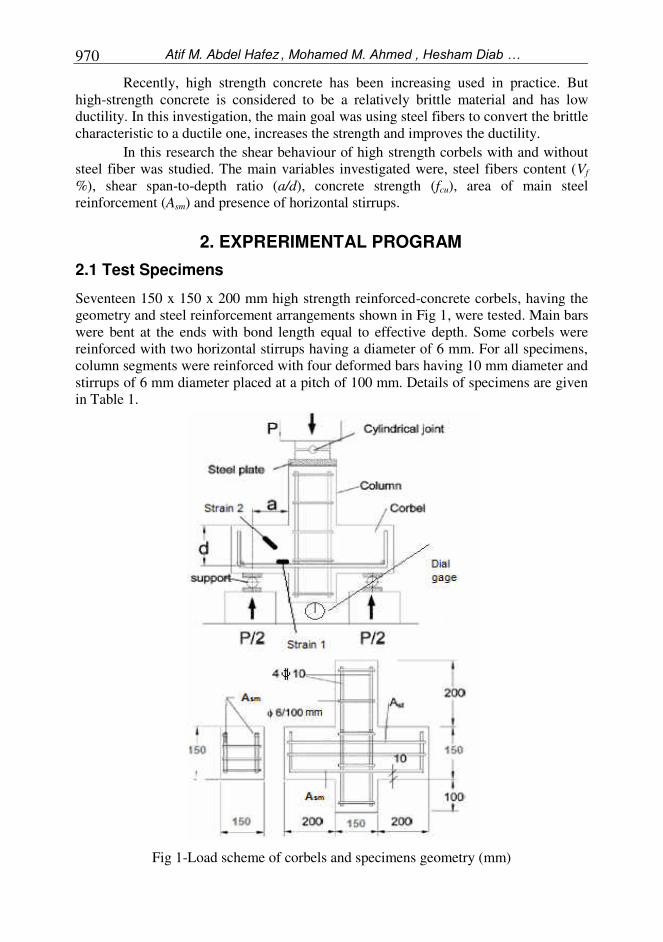
Seventeen 150 x 150 x 200 mm high strength reinforced-concrete corbels, having the
geometry and steel reinforcement arrangements shown in Fig 1, were tested. Main bars
were bent at the ends with bond length equal to effective depth. Some corbels were
reinforced with two horizontal stirrups having a diameter of 6 mm. For all specimens,
column segments were reinforced with four deformed bars having 10 mm diameter and
stirrups of 6 mm diameter placed at a pitch of 100 mm. Details of specimens are given
in Table 1.
Fig 1-Load scheme of corbels and specimens geometry (mm)
SHEAR BEHAVIOUR OF HIGH STRENGTH FIBER … 971
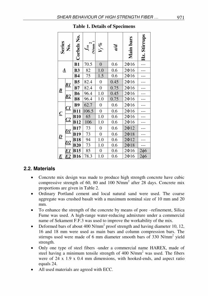
Table 1. Details of Specimens
2.2. Materials
Concrete mix design was made to produce high strength concrete have cubic
compressive strength of 60, 80 and 100 N/mm2 after 28 days. Concrete mix
proportions are given in Table 2.
Ordinary Portland cement and local natural sand were used. The coarse
aggregate was crushed basalt with a maximum nominal size of 10 mm and 20
mm.
To enhance the strength of the concrete by means of pore –refinement, Silica
Fume was used. A high-range water-reducing admixture under a commercial
name of Sekament F.F.3 was used to improve the workability of the mix.
Deformed bars of about 400 N/mm2 proof strength and having diameter 10, 12,
16 and 18 mm were used as main bars and column compression bars. The
stirrups used were made of 6 mm diameter smooth bars of 330 N/mm2 yield
strength.
Only one type of steel fibers -under a commercial name HAREX, made of
steel having a minimum tensile strength of 400 N/mm2 was used. The fibers
were of 24 x 1.9 x 0.4 mm dimensions, with hooked-ends, and aspect ratio
equals 24.
All used materials are agreed with ECC.
Ser
ies
No.
Corb
els
No.
f cu
(N/m
m2
)
Vf %
a/d
Main
bars
Hz.
Sti
rru
ps
A
B1 70.5 0 0.6 2Φ16 ---
B3 82 1.0 0.6 2Φ16 ---
B4 75 1.5 0.6 2Φ16 ---
B
B1 B5 82.4 0 0.45 2Φ16 ---
B7 82.4 0 0.75 2Φ16 ---
B2 B6 96.4 1.0 0.45 2Φ16 ---
B8 96.4 1.0 0.75 2Φ16 ---
C
C1 B9 62.7 0 0.6 2Φ16 ---
B11 106.5 0 0.6 2Φ16 ---
C2 B10 65 1.0 0.6 2Φ16 ---
B12 106 1.0 0.6 2Φ16 ---
D
D1 B17 73 0 0.6 2Φ12 ---
B19 73 0 0.6 2Φ18 ---
D2 B18 94 1.0 0.6 2Φ12 ---
B20 73 1.0 0.6 2Φ18 ---
E
E1 B15 85 0 0.6 2Φ16 2ϕ6
E2 B16 78.3 1.0 0.6 2Φ16 2ϕ6
Atif M. Abdel Hafez , Mohamed M. Ahmed , Hesham Diab …
972
Table 2. Concrete mix proportions
Concrete
Strength
N/mm2
Cement
Kg/m3
Fine
Aggre
gate
Kg/m3
Coarse Aggregate
M.N.S M.N.S
10 mm 20 mm
Kg/m3 Kg/m
3
Silica
Fume
Kg/m3
Super-
Plasticizer
Liter
/m3
Water
Liter
/m3
60 450 600 600 600 70 14 165
80 500 525 600 600 90 17 140
100 550 450 600 600 110 20 138
2.3. Test Setup and Measurements
A hydraulic testing machine with bearing capacity of 600 kN was used. The load
scheme adopted is shown in Fig 1. Corbels tested were supported symmetrically by
two steel hinges placed at a distance (a) from the face of column as shown in Fig. 1. At
each load incensement, vertical deflection of center of bottom surface of column, steel
strain of main bar and concrete strain were recorded. Also for all corbels, the cracking
load and the ultimate load are recorded while the patterns of crack propagation were
observed.
3. TEST RESULTS
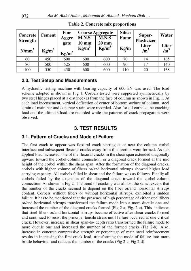
3.1. Pattern of Cracks and Mode of Failure
The first crack to appear was flexural crack starting at or near the column corbel
interface and subsequent flexural cracks away from this section were formed. As this
applied load increased, one of the flexural cracks in the shear span extended diagonally
upward toward the corbel-column connection, or a diagonal crack formed at the mid
height of the corbel within the shear span. After the formation of the diagonal cracks,
corbels with higher volume of fibers or/and horizontal stirrups showed higher load
carrying capacity. All corbels failed in shear and the failure was as follows. Finally all
corbels failed by the extension of the diagonal crack toward the corbel-column
connection. As shown in Fig 2. The trend of cracking was almost the same, except that
the number of the cracks seemed to depend on the fiber or/and horizontal stirrups
content. Corbels without fibers or without horizontal stirrups, exhibited a sudden
failure. It has to be mentioned that the presence of high percentage of either steel fibers
or/and horizontal stirrups transformed the failure mode into a more ductile one and
increased the number of the diagonal cracks formed (Fig 2-a, Fig. 2-e). This indicates
that steel fibers or/and horizontal stirrups became effective after shear cracks formed
and continued to resist the principal tensile stress until failure occurred at one critical
crack. However, increase in shear span-to- depth ratio transformed the failure mode to
more ductile one and increased the number of the formed cracks (Fig 2-b). Also,
increase in concrete compressive strength or percentage of main steel reinforcement
results in increasing the first crack load, transforming the mode of failure into more
brittle behaviour and reduces the number of the cracks (Fig 2-c, Fig 2-d).
SHEAR BEHAVIOUR OF HIGH STRENGTH FIBER … 973
3.2. Load Deflection Curves:
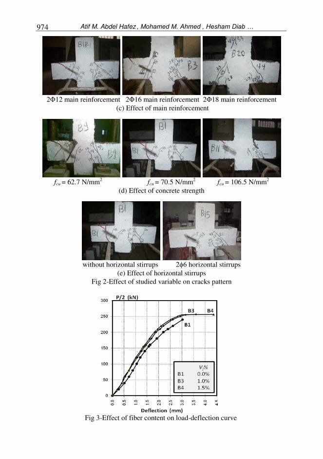
The load-deflection relationships for all tested corbels are shown in (Fig 3 to Fig 7).
From these figures the following observations can be conclude:
When fibers are present, an increase in strength capacity, about 19% in failure
load of corbel was observed and at the same time the ductility improved by
about 20%. It has to be mentioned that an increase of 30% in failure load was
recorded by G. Campione et.al. [1] in case of flexural behavior.
Increasing the shear span-to-depth ratio (a/d) decreasing the failure load and
increasing the deflection of corbels with and without fibers (Fig 4).
As expected, increasing concrete strength leads to increase carrying capacity of
the corbels. Also, it is noticed that the ductility of FRC corbels increased in
comparison with those without fibers. This confirms the advantage of using
fiber in increasing ductility of corbels (Fig 5).
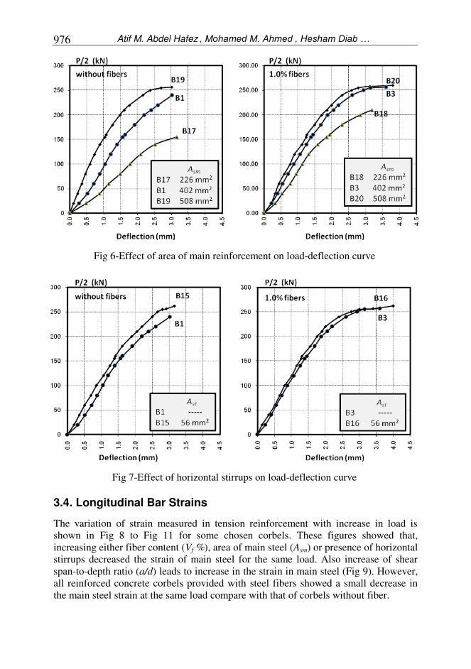
Increase the main steel ratio results in increasing corbel strength. Effect of
addition of fibers to improve behaviour of specimen was clear in case of
corbels having smaller main steel ratio (Fig 6).
Using horizontal stirrups, gives a little increase in corbels strength and
decreases deflection of corbels. Moreover, the addition of fibers allows the
attainment of complete flexural capacity and, consequently, a more ductile
response (Fig 7).
without fibers with 1.0% fibers with 1.5% fibers
(a) Effect of fiber content
a/d = 0.45 a/d = 0.6 a/d = 0.75
(b) Effect of shear span-to-depth ratio
Atif M. Abdel Hafez , Mohamed M. Ahmed , Hesham Diab …
974
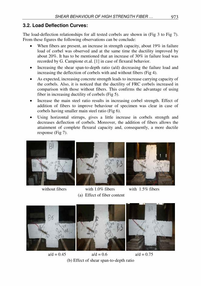
2Φ12 main reinforcement 2Φ16 main reinforcement 2Φ18 main reinforcement
(c) Effect of main reinforcement
fcu = 62.7 N/mm
2 fcu = 70.5 N/mm
2 fcu = 106.5 N/mm
2
(d) Effect of concrete strength
without horizontal stirrups 2ϕ6 horizontal stirrups
(e) Effect of horizontal stirrups
Fig 2-Effect of studied variable on cracks pattern
Fig 3-Effect of fiber content on load-deflection curve
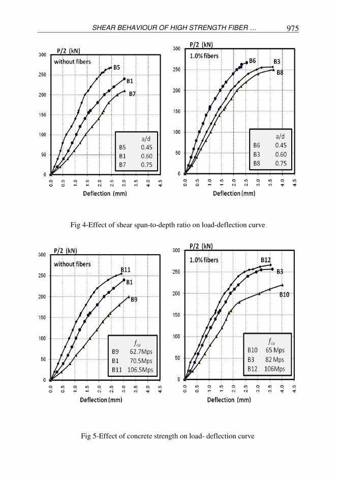
SHEAR BEHAVIOUR OF HIGH STRENGTH FIBER … 975
Fig 4-Effect of shear span-to-depth ratio on load-deflection curve
Fig 5-Effect of concrete strength on load- deflection curve
Atif M. Abdel Hafez , Mohamed M. Ahmed , Hesham Diab …
976
Fig 6-Effect of area of main reinforcement on load-deflection curve
Fig 7-Effect of horizontal stirrups on load-deflection curve
3.4. Longitudinal Bar Strains
The variation of strain measured in tension reinforcement with increase in load is
shown in Fig 8 to Fig 11 for some chosen corbels. These figures showed that,
increasing either fiber content (Vf %), area of main steel (Asm) or presence of horizontal
stirrups decreased the strain of main steel for the same load. Also increase of shear
span-to-depth ratio (a/d) leads to increase in the strain in main steel (Fig 9). However,
all reinforced concrete corbels provided with steel fibers showed a small decrease in
the main steel strain at the same load compare with that of corbels without fiber.
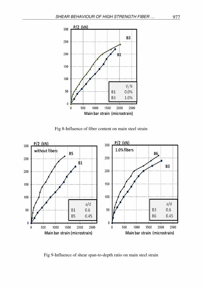
SHEAR BEHAVIOUR OF HIGH STRENGTH FIBER … 977
Fig 8-Influence of fiber content on main steel strain
Fig 9-Influence of shear span-to-depth ratio on main steel strain
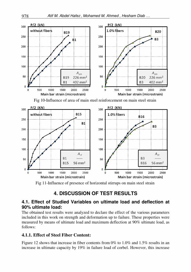
Atif M. Abdel Hafez , Mohamed M. Ahmed , Hesham Diab …
978
Fig 10-Influence of area of main steel reinforcement on main steel strain
Fig 11-Influence of presence of horizontal stirrups on main steel strain
4. DISCUSSION OF TEST RESULTS
4.1. Effect of Studied Variables on ultimate load and deflection at 90% ultimate load: The obtained test results were analyzed to declare the effect of the various parameters
included in this work on strength and deformation up to failure. These properties were
measured by means of ultimate load and maximum deflection at 90% ultimate load, as
follows:
4.1.1. Effect of Steel Fiber Content:
Figure 12 shows that increase in fiber contents from 0% to 1.0% and 1.5% results in an
increase in ultimate capacity by 19% in failure load of corbel. However, this increase
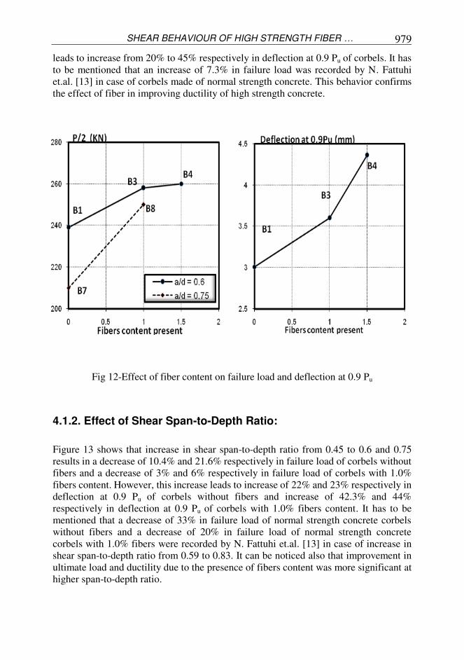
SHEAR BEHAVIOUR OF HIGH STRENGTH FIBER … 979
leads to increase from 20% to 45% respectively in deflection at 0.9 Pu of corbels. It has
to be mentioned that an increase of 7.3% in failure load was recorded by N. Fattuhi
et.al. [13] in case of corbels made of normal strength concrete. This behavior confirms
the effect of fiber in improving ductility of high strength concrete.
Fig 12-Effect of fiber content on failure load and deflection at 0.9 Pu
4.1.2. Effect of Shear Span-to-Depth Ratio:
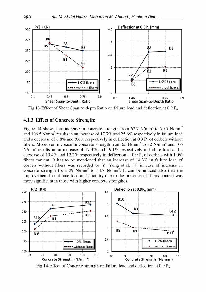
Figure 13 shows that increase in shear span-to-depth ratio from 0.45 to 0.6 and 0.75
results in a decrease of 10.4% and 21.6% respectively in failure load of corbels without
fibers and a decrease of 3% and 6% respectively in failure load of corbels with 1.0%
fibers content. However, this increase leads to increase of 22% and 23% respectively in
deflection at 0.9 Pu of corbels without fibers and increase of 42.3% and 44%
respectively in deflection at 0.9 Pu of corbels with 1.0% fibers content. It has to be
mentioned that a decrease of 33% in failure load of normal strength concrete corbels
without fibers and a decrease of 20% in failure load of normal strength concrete
corbels with 1.0% fibers were recorded by N. Fattuhi et.al. [13] in case of increase in
shear span-to-depth ratio from 0.59 to 0.83. It can be noticed also that improvement in
ultimate load and ductility due to the presence of fibers content was more significant at
higher span-to-depth ratio.
Atif M. Abdel Hafez , Mohamed M. Ahmed , Hesham Diab …
980
Fig 13-Effect of Shear Span-to-depth Ratio on failure load and deflection at 0.9 Pu
4.1.3. Effect of Concrete Strength:
Figure 14 shows that increase in concrete strength from 62.7 N/mm2 to 70.5 N/mm
2
and 106.5 N/mm2
results in an increase of 17.7% and 25.6% respectively in failure load
and a decrease of 6.8% and 9.6% respectively in deflection at 0.9 Pu of corbels without
fibers. Moreover, increase in concrete strength from 65 N/mm2 to 82 N/mm
2 and 106
N/mm2 results in an increase of 17.3% and 19.1% respectively in failure load and a
decrease of 10.4% and 12.2% respectively in deflection at 0.9 Pu of corbels with 1.0%
fibers content. It has to be mentioned that an increase of 14.3% in failure load of
corbels without fibers was recorded by Y. Yong et.al. [4] in case of increase in
concrete strength from 39 N/mm2 to 54.7 N/mm
2. It can be noticed also that the
improvement in ultimate load and ductility due to the presence of fibers content was
more significant in those with higher concrete strengthes.
Fig 14-Effect of Concrete strength on failure load and deflection at 0.9 Pu
SHEAR BEHAVIOUR OF HIGH STRENGTH FIBER … 981
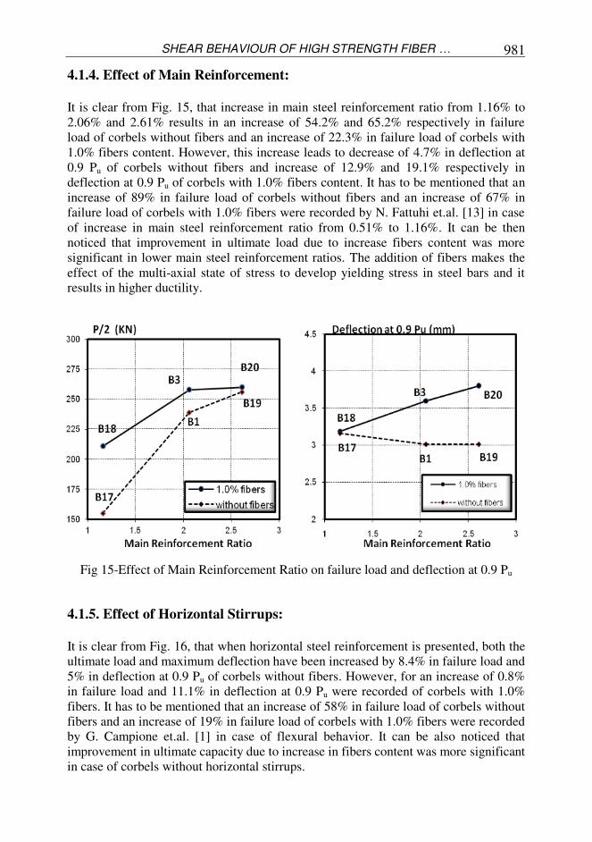
4.1.4. Effect of Main Reinforcement:
It is clear from Fig. 15, that increase in main steel reinforcement ratio from 1.16% to
2.06% and 2.61% results in an increase of 54.2% and 65.2% respectively in failure
load of corbels without fibers and an increase of 22.3% in failure load of corbels with
1.0% fibers content. However, this increase leads to decrease of 4.7% in deflection at
0.9 Pu of corbels without fibers and increase of 12.9% and 19.1% respectively in
deflection at 0.9 Pu of corbels with 1.0% fibers content. It has to be mentioned that an
increase of 89% in failure load of corbels without fibers and an increase of 67% in
failure load of corbels with 1.0% fibers were recorded by N. Fattuhi et.al. [13] in case
of increase in main steel reinforcement ratio from 0.51% to 1.16%. It can be then
noticed that improvement in ultimate load due to increase fibers content was more
significant in lower main steel reinforcement ratios. The addition of fibers makes the
effect of the multi-axial state of stress to develop yielding stress in steel bars and it
results in higher ductility.
Fig 15-Effect of Main Reinforcement Ratio on failure load and deflection at 0.9 Pu
4.1.5. Effect of Horizontal Stirrups:
It is clear from Fig. 16, that when horizontal steel reinforcement is presented, both the
ultimate load and maximum deflection have been increased by 8.4% in failure load and
5% in deflection at 0.9 Pu of corbels without fibers. However, for an increase of 0.8%
in failure load and 11.1% in deflection at 0.9 Pu were recorded of corbels with 1.0%
fibers. It has to be mentioned that an increase of 58% in failure load of corbels without
fibers and an increase of 19% in failure load of corbels with 1.0% fibers were recorded
by G. Campione et.al. [1] in case of flexural behavior. It can be also noticed that
improvement in ultimate capacity due to increase in fibers content was more significant
in case of corbels without horizontal stirrups.

Atif M. Abdel Hafez , Mohamed M. Ahmed , Hesham Diab …
982
Fig 16-Effect of Hz-Stirrups Reinforcement Ratio on failure load and deflection at 0.9 Pu
4.2. Comparison between Experimental and Predicted Ultimate Loads: Many equations have been proposed to estimate the ultimate strength of reinforced
concrete corbels. Among them, the ACI code [13], Fattuhi equation [10], Truss method
[14] and G. Compione propose [1].
These equations can briefly presented as follows:
a) ACI code equation [14]
The ACI current design produces for corbels were based on shear friction
and empirical relationship based on the flexural capacity of the section. The
smallest of the three values is used for design. The three basic equations
allowed for design of the corbels by ACI-318 are given as follows:
Shear friction strength:
kN (1)
Flexural strength:
kN.m (3)
Maximum shear strength
Vu = 0.2 fc' bd kN (4)
Where:Vu = corbel strength (N), ø = strength reduction factor (assumed to be
1.0), µ =coefficient of friction (assumed to be 1.4 for monolithic concrete),
Av = area of reinforcement extending across the critical section (mm2),
fy = yield strength of the main reinforcement (N/mm2), Mu = flexural moment
(N.m), a = shear span length (mm), b = width of corbels (mm), fc' = cylinder
compressive strength (N/mm2), d = overall depth of corbel (mm).
In using the above equations, cylinder compressive strength of concrete fc' is
required. For the reason that fc' was not directly available from the tests, the
following conversion formula proposed by Neville [15] was employed.
kN (2)

SHEAR BEHAVIOUR OF HIGH STRENGTH FIBER … 983
N/mm2 (5)
b) Fattuhi equation [10]
The predicted values are obtained by using the following modified shear-
friction equation suggested by Fattuhi [10]
Vu = ø (η Avf ffu µ) + ø (Av fy µ) N (6)
Where: η = overall fiber efficiency factor = 0.1, Avf = total area of fiber at
critical section (mm2), ffu = ultimate tensile strength of the fiber (N/mm
2),
ø = strength reduction factor (assumed to be 1.0), µ =coefficient of friction
(assumed to be 1.4 for monolithic concrete), fy = yield strength of the main
reinforcement (N/mm2).
c) Truss analogy method [14]
The equations of the truss analogy method (Fig 17) proposed by Hagberg
[14], can be listed as follows:
Fig 17-Truss analogy method [15]
Fs = Asm fy N (7)
Where: Fs = force in main steel (N), fy = yield strength of the main
reinforcement (N/mm2), β = angle of inclination of the compressive concrete
strut with vertical column
d) G. Campione proposes et.al. [1]
Where: c = cover thickness (mm), Ect = modulus of elasticity of fibers
concrete (N/mm2), Es = elastic modulus of steel (N/mm
2), F = fiber
factor, fc' = peak compressive strength of concrete (N/mm2), fctf = ultimate
tensile strength of fibers concrete (N/mm2), fy = yielding stress (N/mm
2),
Vn1 = ultimate shear force in case of steel failure in principal truss
Strut
Tie
N (8)

Atif M. Abdel Hafez , Mohamed M. Ahmed , Hesham Diab …
984
(N/mm2), Vn2 = ultimate shear force in case of compressive failure in
principal truss (N/mm2), xc = neutral axis depth (mm), α = angle between
strut and tie of principal truss, χ = a dimensional interpolating function
(mm).
The smaller of the two values is used to predicate the ultimate load.
Table 3 and Fig. 18 show a compression between the experimental values of
corbels capacity with those derived from the above equations. It can be noticed
that G. Campione's equations [1] is estimated satisfactorily the ultimate load
for high strength fiber reinforced concrete corbels.
Table 3. Corbels results and comparison between experimental and
predicted ultimate load
/
sdsa
D
cccc
cbel
s
Experimental Results
AC
I 318
-08
Cod
e
[14]
Fatt
uh
i
Eq
uati
on
[10]
Tru
ss
Met
hod
[15]
G.
Com
pio
ne
Pro
pose
[1]
Pcr/2
(kN) cr
(mm)
Pu/2
(kN) 90
(mm)
Mod
e of
Fail
ure
Pu/2
(kN
)
Exp
. /
Pre
.
Pu/2
(kN
)
Exp
. /
Pre
.
Pu/2
(kN
)
Exp
. /
Pre
.
Pu/2
(kN
)
Exp
. /
Pre
.
A
B1 45 0.43 239 3.01 C.S. 236 1.01 236 1.01 235 1.02 235 1.02
B3 55 0.83 258 3.60 F.S. 236 1.09 264 0.98 240 1.07 254 1.01
B4 60 1.42 248 4.36 F.S. 236 1.05 277 0.89 237 1.05 257 0.97
B
B1 B5 45 0.87 268 2.47 C.S. 236 1.13 236 1.13 300 0.89 300 0.89
B7 45 0.31 210 3.03 D.S. 209 1.00 236 0.89 199 1.05 199 1.05
B2 B6 55 0.97 266 2.53 C.S. 236 1.13 264 1.01 308 0.86 326 0.82
B8 55 1.09 250 3.64 F.S. 212 1.18 264 0.95 202 1.24 217 1.15
C
C1 B9 45 0.16 203 3.06 D.S. 236 0.86 236 0.86 231 0.88 231 0.88
B11 45 0.35 255 2.91 C.S. 236 1.08 236 1.08 248 1.03 248 1.03
C2 B10 55 1.10 220 4.02 F.S. 236 0.93 264 0.83 232 0.95 244 0.9
B12 55 1.11 262 3.53 F.S. 236 1.11 264 0.99 248 1.06 265 0.99
D
D1 B17 45 0.51 155 3.16 C.S. 133 1.17 133 1.17 142 1.09 142 1.09
B19 45 0.25 256 3.01 D.S. 299 0.86 299 0.86 288 0.89 288 0.89
D2 B18 55 1.33 211 3.19 F.S. 133 1.59 160 1.32 146 1.45 162 1.3
B20 55 0.77 258 3.60 C.S. 299 0.86 327 0.79 288 0.90 300 0.86
E E1 B15 55 0.54 259 3.16 F.S. 262 0.99 263 0.98 251 1.03 251 1.03
E2 B16 60 1.24 260 4.00 F.S. 261 0.99 290 0.89 251 1.03 268 0.97
Mean 1.060 0.978 1.028 0.991
S.D. 0.172 0.136 0.146 0.119
Where:
Pcr. = cracking load. C.S. = Catastrophic shear
Pu. = ultimate load D.S. = diagonal shear
δcr = deflection at cracking load. F.S. = flexural shear
δ90= deflection at 0.9 Pu
Gro
up
/
Ser
ies
Corb
els

SHEAR BEHAVIOUR OF HIGH STRENGTH FIBER … 985
Fig 18-Comprasion between experimental and predicted ultimate loads
5. CONCLUSIONS
Based on the test results and the above discussions, the following conclusions can be
drawn:
The presence of high percentage of fibers or/and horizontal stirrups
transformed the mode of failure of the tested corbels into a more ductile one and
increased the number of diagonal cracks.
Addition of steel fibers not only improves the shear strength of the tested
corbels, but also increases the stiffness of these corbels. This improvement is more
significant in case of corbels without stirrups.
The improvement in shear strength of tested corbels was more significant for
corbels with low main reinforcement ratio or these with large shear span-to-depth ratio
or those with lower concrete strength.
Increasing the main reinforcement results in an increase in the ultimate shear
strength and leads to more ductile failure especially, when the fiber is presented.
Ultimate shear capacity of high strength fiber reinforced concrete corbels can
be reasonably predicted by using Compione's equations.
REFERENCES
1. Giuseppe Campione, Lidia La Mendola, and Maria Letizia Mangiavillano, "Steel
Fiber-Reinforced Concrete Corbels: Experimental Behavior and Shear Strength
Prediction", ACI Structural Journal, V. 104, No. 5, Sep.-Oct. 2007.
2. Collins, M. P., and Michell, D., "Rational approach to shear design-the 1984
Canadian code provisions" ACI Struct. J., V. 83, No. 6, 1986.
3. Solanki, H., and Sabnis, G. M., "Reinforced concrete corbels-simplified" ACI
Struct. J., V. 84, No. 5, 1987.

Atif M. Abdel Hafez , Mohamed M. Ahmed , Hesham Diab …
986
4. Yong, Y., and Balaguru, P., "Behaviour of Reinforced High-Strength-Concrete
Corbels" Journal of Structural Engineering, ASCE, V. 120, No. 4, 1994.
5. Foster, S. J., Powell, R. E., and Selim, H. S., "Performance of high-strength
concrete corbels" ACI Struct. J., V. 93, No. 5, 1996.
6. Foster, S. J., and Malik, A. R., "Evaluation of efficiency factor models used in
strut-and-tie modeling of nonflexural members" J. Struct. Eng., Vo. 128, No. 5,
2002.
7. Hwang, S., Lu, W., and Lee, H., "Shear strength prediction for reinforced concrete
corbels" ACI Struct. J., V. 97, No. 4, 2000.
8. Hwang, S., and Lee, H., "Strength prediction for discontinuity regions by softened
strut and tie model" J. Struct. Eng., V. 128, No. 12, 2002.
9. Russo, G., Venir, R., Pauletta, M., and Somma, G. "Reinforced concrete corbels
shear strength model and design formula" ACI Struct. J., V. 103, No. 1, 2006.
10. Fattuhi Nijad I., "SFRC Corbels Tests," ACI Structural Journal, V. 84, No. 2,
Mar.-Apr. 1987.
11. Hashim M. S. Abdul-Wahab, "Strength of Reinforced Concrete Corbels with
Fibers," ACI Structural Journal,V. 86, Nov.-Dec. 1989.
12. Giuseppe Campione, "Performance of Steel Fibrous Reinforced Concrete Corbels
Subjected to Vertical and Horizontal Loads," Journal of Structural Engineering, V.
135, No. 5, May. 2009.
13. Fattuhi Nijad, "Reinforced Steel Fiber Concrete Corbels with Various Shear Span-
to-Depth Ratios", ACI Materials Journal V. 86, No. 6, Nov-Dec 1989.
14. ACI committee 318. "Building Code Requirement for Reinforcement Concrete
(ACI 318-08)," American Concrete Institute, Detroit, 2008.
15. Hagberg, Thore, "Design of Concrete Brackets; On the Application of the Truss
Analogy", ACI Journal, Proceedings V. 80, No. 1, January 1983
16. Nevielle, J. Taub, "Resistance to shear Reinforced Concrete Beams", ACI
Structural Journal, V. 57, No. 6, November 1960.
SHEAR BEHAVIOUR OF HIGH STRENGTH FIBER … 987
مصنوعة من خرسانة خرسانية ا وابيل ا قص فى ا سلوك ا
ي صلبعا ياف من ا مقاومة تحتوى على أ ة ا
دراسة معمليةاجريت ا وعة ا مص مسلحة ا ية ا خرسا وابيل ا قص فى ا بحث بغرض دراسة سلوك ا فى هذا امعملية على سب تجارب ا قد اجريت ا ها . و صلب او بدو ياف من ا مقاومة تحتوى على ا ية ا ة عا ة عمن خرسا
متغي ت ا ا ابوى و تى تمت دراستها عشر ى :ارات ا تاية -1 خرسا خلطة ا صلب با ياف ا % Vf)) سبة أابوى -2 ل فعال عمق ا ى ا قص ا (a/d ) سبة بحر اة -3 لخرسا ضغط (fcu) مقاومة ارئيسى مساحة مقطع -4 تسليح ا (Asm) حديد اات افقية من عدمه -5 ا وجود
دراسة مقارة ك تم فى هذ ا حصول عليها معمليا بتلك ذ تى تم ا وابيل و ا ل قصوى قص ا مقاومة امعادات محسوبة من ا مقترحةا ى . ا ود اأمري ب معادات ا بجا
تى تم تائج ا حصول عليها و من اهم ا بحث ما يلى : فىا هذا ااحية حمل .1 قص من قصير فى ا وابيل ا ية يحسن من سلوك ا خرسا خلطة ا صلب با ياف ا وجود ا
ية . ممطو ك ا ذ قص اأقصى و ا
اقص مع .2 قصير يت وابيل ا ل قصوى قص ا ياف فى زيادة مقاومة ا ات اافقية .وجود فاعلية اأ ا ا
ياف بوضوح فى .3 ل من يظهر ايضا دور اأ قص ااقصىحم زيادة ية ل ا ممطو قصير و ا وابيل ا لفعال عمق ا ى ا قص ا سبة بحر ا دما يزيد خفضة او ع رئيسى م تسليح ا سبة ا ون دما ت ع
ابوى. ل
ة .4 وعة من خرسا مص ية ا خرسا قصيرة ا وابيل ا ل قصوى قص ا تائج مقارة قيم مقاومة ا أظهرت ياف مقاومة تحتوى على ا ية ا تى تمعا صلب و ا حصول عليها ا محسوبه من معمليا ا بتلك ا
موذج متوفر ان معادات معادات ا تائج مرضية. G. Campineا تعطى