Embed Size (px)
DESCRIPTION
Shear and Diagonal Tension. Acknowledgement. This Powerpoint presentation was prepared by Dr. Terry Weigel, University of Louisville. This work and other contributions to the text by Dr. Weigel are gratefully acknowledged. Shear Stresses in Concrete Beams. Flexural stress. Shear stress. - PowerPoint PPT Presentation
Citation preview

Shear and Diagonal TensionShear and Diagonal Tension
1

Acknowledgement
This Powerpoint presentation was prepared by Dr. Terry Weigel, University of Louisville. This work and other contributions to the text by Dr. Weigel are gratefully acknowledged.
2

Shear Stresses in Concrete Shear Stresses in Concrete BeamsBeams
3
McfI
Diagonal tension – Mohr’s circle
Principal stresses2
2
2 2pf ff v
Flexural stress
Shear stress2tan 2 vf
VQvIb
Principal angle

Shear Strength of ConcreteShear Strength of Concrete
4
ACI Code Equation 11-3 – conservative but easy to use
ACI Code Equation 11-5 – less conservative but “difficult” to use

Shear Strength of ConcreteShear Strength of Concrete
5
'
'
'
2
1.9 2500
3.5
n c s
u n c s
c c w
uc c w w
u
c w
V V VV V V V
V f b d
V dV f b dM
f b d
1
sw
w
u
u
Ab d
V dM
Equation 11-3
Equation 11-5

Shear Cracking of Reinforced Shear Cracking of Reinforced BeamsBeams
6
Flexural shear crack – initiate from top of flexural crack
For flexural shear cracks to occur, moment must be larger than the cracking moment and shear must be relatively large
Flexural shear cracks oriented at angle of approximately 45 degrees to the longitudinal beam axis

Flexural-shear CracksFlexural-shear Cracks
7

Shear Cracking of Reinforced Shear Cracking of Reinforced BeamsBeams
8
Web shear crack – form independently
Typically occur at points of small moment and large shear
Occur at ends of beams at simple supports and at inflection points at continuous beam

Web-shear CracksWeb-shear Cracks
9

Web ReinforcementWeb Reinforcement
10
Stirrups
Hangers
At a location, the width of a diagonal crack is related to the strain in the stirrup – larger strain = wider crack
To reduce crack width, stirrup yield stress is limited to 60 ksi

Web ReinforcementWeb Reinforcement
11
Small crack widths promote aggregate interlock
Limiting stirrup yield stress also reduces anchorage problems

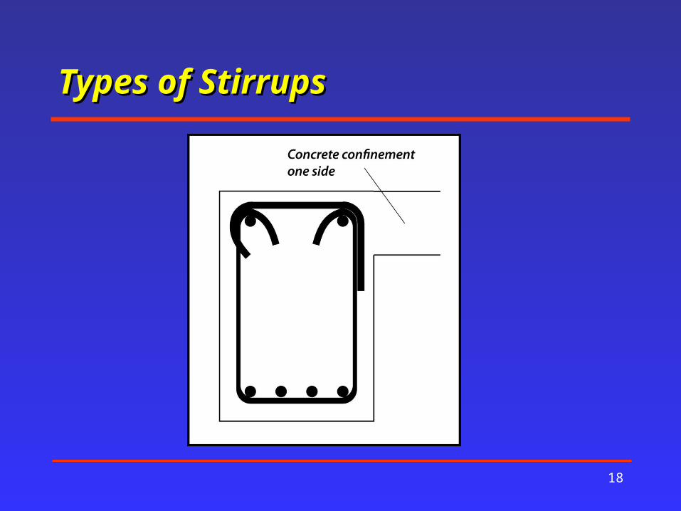
Types of StirrupsTypes of Stirrups
12

Types of StirrupsTypes of Stirrups
13

Types of StirrupsTypes of Stirrups
14

Types of StirrupsTypes of Stirrups
15

Types of StirrupsTypes of Stirrups
16

Types of StirrupsTypes of Stirrups
17
Types of StirrupsTypes of Stirrups
18

Types of StirrupsTypes of Stirrups
19

Types of StirrupsTypes of Stirrups
20

Behavior of Beams with Web Behavior of Beams with Web ReinforcementReinforcement
21
Truss analogy
Concrete in compression is top chord
Longitudinal tension steel is bottom chord
Stirrups form truss verticals
Concrete between diagonal cracks form the truss diagonals

Truss AnalogyTruss Analogy
22

Required Web Reinforcement Required Web Reinforcement – ACI Code– ACI Code
23
Required for all flexural members except:
Footings and solid slabs
Certain hollow core units
Concrete floor joists
Shallow beams with h not larger than 10”

Required Web Reinforcement Required Web Reinforcement – ACI Code– ACI Code
24
Required for all flexural members except:Beams built integrally with slabs and h less than 24 in. and h not greater than the larger of 2.5 times the flange
thickness or one-half the web widthBeams constructed with steel fiber-reinforced concrete with strength not exceeding 6,000 psi and
'2u c wV f b d

StirrupsStirrups
25
Diagonally inclined stirrups more efficient than vertical stirrups
Not practical
Bent-up flexural bars can be used instead

Bent-up Bar Web Bent-up Bar Web ReinforcementReinforcement
26

Shear CrackingShear Cracking
27
The presence of stirrups does not materially effect the onset of shear cracking
Stirrups resist shear only after cracks have occurred
After cracks occurs, the beam must have sufficient shear reinforcement to resist the load not resisted by the concrete in shear

Benefits of StirrupsBenefits of Stirrups
28
Stirrups carry shear across the crack directly
Promote aggregate interlock
Confine the core of the concrete in the beam thereby increasing strength and ductility
Confine the longitudinal bars and prevent cover from prying off the beam
Hold the pieces on concrete on either side of the crack together and prevent the crack from propagating into the compression region

Design for ShearDesign for Shear
29
0.75u n c sV V V V
Stirrups crossing a crack are assumed to have yielded
Shear crack forms at a 45 degree angle

Design for ShearDesign for Shear
30
sin cos
y
y
y
s v
s v
v
s
v ys
V A f n
dns
dV A fs
A f ds
VA f d
Vs
ACI Code Equation 11-15
ACI Code Equation 11-16

Design for ShearDesign for Shear
31

ACI Code Requirements for ACI Code Requirements for ShearShear
32
ACI Code Section 11.4.6.1 – if Vu exceeds one-half Vc, stirrups are requiredWhen shear reinforcement is required, ACI Code Section 11.4.6.3 specifies a minimum amount: '
,minimum
0.75
50
c wv
y
w
y
f b sA
f
b sf

ACI Code Requirements for ACI Code Requirements for ShearShear
33
To insure that every diagonal crack is crossed by at least one stirrup, the maximum spacing of stirrups is the smaller of d/2 or 24 in.
If maximumspacingsare halved. See ACI Code Section
11.4.5.3
'4s c wV f b d

ACI Code Requirements for ACI Code Requirements for ShearShear
34
See ACI Code Section 11.4.7.9
'8s c wV f b d
ACI Code Section 11.1.2 -> ' 100 psicf
Stirrups should extend as close as cover requirements permit to the tension and compression faces of the member - anchorage

ACI Code Requirements for ACI Code Requirements for ShearShear
35
Stirrup hook requirements shown on the next slide. See ACI Code Section 8.1 and 12.13
In most cases, beam can be designed for shear at a distance d from the face of the support . See next three slides for exceptions.
In deep beams ( l /d < 4), large shear may affect flexural capacity

End Shear Reduction Not End Shear Reduction Not PermittedPermitted
36

End Shear Reduction Not End Shear Reduction Not PermittedPermitted
37

CorbelsCorbels
38

ACI Code Requirements ACI Code Requirements Stirrup HooksStirrup Hooks
39

ACI Code Requirements ACI Code Requirements Stirrup HooksStirrup Hooks
40

ACI Code Requirements ACI Code Requirements Stirrup HooksStirrup Hooks
41

Shear Design ExamplesShear Design Examples
42

Example 8.1Example 8.1
43
Determine the minimum cross section required for a rectangular beam so that no shear reinforcement is required. Follow ACI Code requirements and use a concrete strength of 4,000 psi. Vu = 38 k.

Example 8.1Example 8.1
44
'2 0.75 2 1.0 4000
94.87
c c w w
w
V f b d b d
b d
Shear strength provided by concrete

Example 8.1Example 8.1
45
ACI Code Section 11.4.6.1 requires:
Use a 24 in x 36 in beam (d = 33.5 in)
2
94.87 38,000 lb2
801.1
cu
w
w
VV
b d
b d

Example 8.2Example 8.2
46
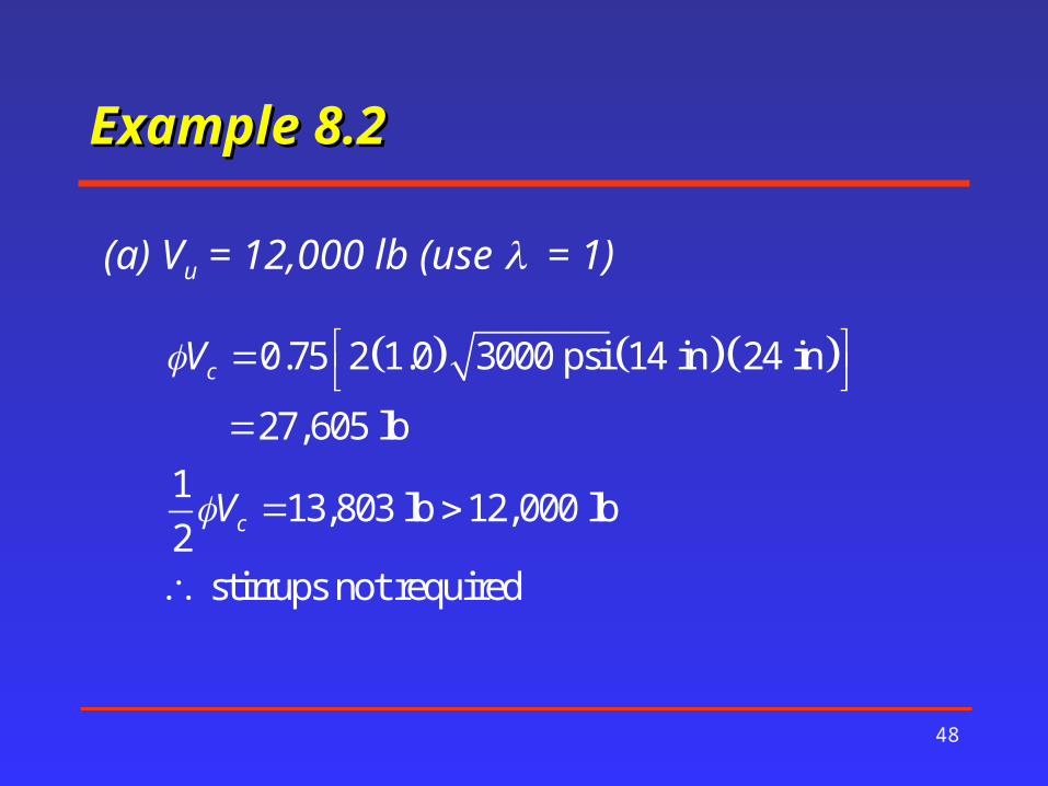
The beam shown in the figure was designed using a concrete strength of 3,000 psi and Grade 60 steel. Determine the theoretical spacing for No 3 U-shaped stirrups for the following values for shear:(a) Vu = 12,000 lb(b) Vu = 40,000 lb(c) Vu = 60,000 lb(d) Vu = 150,000 lb

Example 8.2Example 8.2
47
Example 8.2Example 8.2
48
0.75 2 1.0 3000 psi 14 in 24 in
27,605 lb1 13,803 lb 12,000 lb2
stirrups not required
c
c
V
V
(a) Vu = 12,000 lb (use = 1)

Example 8.2Example 8.2
49
2
40,000 lb 27,605 lb 16,527 lb0.75
2 0.11 in 60,000 psi 24 in19.17 in
16,527 lb
n c s u
u cs
v y
s
V V V VV VV
A f ds
V
(b) Vu = 40,000 lbStirrups are needed
since 2c
uVV

Example 8.2Example 8.2
50
2
'
2
2 0.11 in 60,000 psi22.95 in
0.75 3000 psi 14 in0.75
2 0.11 in 60,000 psi18.86 in
50 50 14 in
v y
c w
v y
w
A fs
f b
A fs
b
(b) (con’t) Maximum spacing to provide minimum Av

Example 8.2Example 8.2
51
16,527 lb 4 3000 psi 24 in 14 in 73,614 lb
12 in2
sV
ds
(b) (con’t) ACI Code maximum spacing

Example 8.2Example 8.2
52
2
60,000 lb 27,605 lb 43,193 lb0.75
2 0.11 in 60,000 psi 24 in
43,193 lb 7.33 in
n c s u
u cs
v y
s
V V V VV VV
A f ds
V
(c) Vu = 60,000 lb

Example 8.2Example 8.2
53
2
'
2
2 0.11 in 60,000 psi22.95 in
0.75 3000 psi 14 in0.75
2 0.11 in 60,000 psi18.86 in
50 50 14 in
v y
c w
v y
w
A fs
f b
A fs
b
(c) (con’t) ACI Code maximum spacing

Example 8.2Example 8.2
54
43,193 lb 4 3000 psi 24 in 14 in 73,614 lb
12 in2
sV
ds
(c) (con’t) ACI Code maximum spacing
Use s = 7.33 in

Example 8.2Example 8.2
55
'
150,000 lb 27,605 lb 163,193 lb0.75
163,193 lb 8 3000 psi 14 in 24 in 147,228 lb
a larger beam or higher value of is required
n c s u
u cs
c
V V V VV VV
f
(d) Vu = 150,000 lb

Example 8.3Example 8.3
56
Select No 3 U-shaped stirrups for the beam shown. The beam carries loads of D = 4 k/ft and L= 6 k/ft. Use normal weight concrete with a strength of 4,000 psi and Grade 60 steel.

Example 8.3Example 8.3
57

Example 8.3Example 8.3
58

Example 8.3Example 8.3
59
'
1.2 4 k ft 1.6 6k ft 14.4k ft
(left end) 7 ft 14.4k ft 100.8 k
84 in 22.5 in( from face of support) 100.8 k84 in
73.8 k
2
0.75 2 1 4000 psi 15 in 22.5 in
32,018 lb
u
u
u
c c w
w
V
V d
V f b d

Example 8.3Example 8.3
60
Vu = 100.8 – 14.4x

Example 8.3Example 8.3
61
'
max
73,800 lb 32,018 lb 41,782 lb41,782 lb 55,709 lb
0.75
4 4 4000 psi 15 in 22.5 in 85,382 lb
Because 85,380 lb 55,709 lb
11.25 in2
u c s
s u c
s
c w
s
V V VV V V
V
f b d
Vds

Example 8.3Example 8.3
62

Example 8.3Example 8.3
63
2
2
'
Maximum theoretical spacing
2 0.11 in 60,000 psi 22.5 in
55,709 lb 5.33 inMaximum spacing to provide minimum stirrup area
2 0.11 in 60,000 psi18.55 in
0.75 4000 psi 15 in0.75
50
v y
s
v y
c w
v y
A f ds
V
A fs
f b
A fb
22 0.11 in 60,000 psi17.60 in
50 15 inw

Example 8.3Example 8.3
64
At what location along the beam is s = 9 in OK?
32,018 0.75
2(0.11)(60,000)(22.5)32,018 0.75 56,7689
100.8 14.4 56.77 , 3.058 36.69
v yu c s
u
A f dV V V
s
lb
V x k x ft in

Example 8.3Example 8.3
65
32,016 16,009 16.012 2
100.8 14.4 16.01 , 5.89 70.66
cu
u
VV lb k
V x k x ft in
Terminate stirrups when Vu < Vc/2

Example 8.3Example 8.3
66
Distance from face of support
(ft)
Vu (lb) Vs (lb) Theoretical s (in)
1.875’=22.5” 73,800 55,709 5.33
2’ = 24” 72,000 53,309 5.57
3’ = 36” 57,600 34,109 8.71
3.058’= 36.69” 56,768 33,000 9
4’= 48” 43,200 14,909 > Maximum d/2 = 11.25
5.89’ = 70.66” 16,008 - terminate

Example 8.3Example 8.3
67
Corrected spacing: Cumulative (in) 1 @ 2 in = 2 in 2
7 @ 5 in = 35 in 37 > 36.69
4 @ 9 in = 36 in 73 >70.66

Example 8.4Example 8.4
68
Determine the value of Vc at a distance 3 ft from the left end of the beam of Example 8.3, using ACI Equation 11-5

Example 8.4Example 8.4
69
' '1.9 2500 3.5
(at 3 ft) 7 ft 14.4k ft 3 ft 14.4k ft 57.6 k
(at 3 ft) 3 ft 100.8 k 3 ft 1.5 ft 14.4k ft
237.6 k-ft
uc c w w c w
u
u
u
V dV f b d f b dM
V
M

Example 8.4Example 8.4
70
25.06 in 0.015015 in 22.5 in
57.6 k 22.5 in0.456 1.0 use 0.456
12in ft 237.6 k-ft
1.9 1 4000 psi 2500 0.0150 0.456 15 in 22.5 in
46,328 lb
3.5 1 4000 psi 15 in 22.5 in 74,709 lb
w
u
u
c
V dM
V
Using the simplified formula (ACI Eq. 11-3) for Vc results in a value of 42,691 lb1-5

Example 8.5Example 8.5
71
Select No 3 U-shaped stirrups for the beam of Example 8.3, assuming that the live load is placed to produce maximum shear at the beam centerline, and that the live load is placed to produce the maximum shear at the beam ends.

Example 8.5Example 8.5
72
Positioning of live load to produce maximum shear at the beam ends is the same as used in Example 8.3; that is, the full factored dead and live load is applied over the full length of the beam. Positioning of the live load to produce maximum positive shear at the beam centerline is shown in the figure on the next slide.

Example 8.5Example 8.5
73

Example 8.5Example 8.5
74
(centerline) 50,400 lb 7 ft 4.8k ft 1000lb k
16,800 lbuV
Vu at face of left support = 100,800 lb (from Ex. 8.3)
From the loads shown on the previous slide, the factored load on the left half of the beam is wu = 1.2 (4 k/ft) = 4.8 k/ft. The left reaction is obtained by summing moments about the right support, and the shear at midspan is:

Example 8.5Example 8.5
75
Approximating the shear envelope with a straight line between 100.8 k at the face of the support and 16.8 k at midspan
Vc = 32.018 k
Vc /2 = 16.009 k
100.8 k
78.3 k
16.8 k
Stirrups carry shear
concrete carries shear
Slope = (100.8 -16.8)/7 ft = 12 k/ft

Example 8.5Example 8.5
76
'
22.5(d from face of support) 100,800 lb - (12,000 )( )12 /
78,300
2 = 2 1 4000 psi 15 in 22.5 in
= 42,691 lbV (0.75)(42,691) 32,018
u
c c w
c
inlbV ft in ftlb
V f b d
lb

Example 8.5Example 8.5
77
Design the stirrups using the shear envelop
32,018 16,009 16.012 2
100.8 12 16.01 , 7.06 84.79
cu
u
VV lb k
V x k x ft in
Terminate stirrups when Vu < Vc/2
This location is past midspan, so stirrups cannot be terminated

Example 8.5Example 8.5
78
78,300 lb 32,018 lb 46,282 lb46,280 lb 61,709 lb
0.75(2)(0.11)(60,000)(22.5)s= 4.81
61,709
u c s
s u c
s
v y
s
V V VV V V
V
A f din
V
At x = d = 22.5 inAt x = d = 22.5 in
Results of similar calculations at other assumed values of x are shown in the table that follows

Example 8.5Example 8.5
79
At what location along the beam is s = 9 in OK?
32,018 0.75
2(0.11)(60,000)(22.5)32,016 0.75 56,7689
100.8 12 56.77 , 3.67 44.03
v yu c s
u
A f dV V V
s
lb
V x k x ft in
Results of similar calculations for s = 6 in and s = 11 in are shown in the table that follows

Example 8.5Example 8.5
80
Distance from face of support (ft)
Vu (lb) Vs (lb) Theoretical s (in)
0 to d = 1.875 78,300 61,709 4.81
2 76,800 59,709 4.97
2.638’=31.66” 69,143 49,500 6.00
3 64,800 43,709 6.79
3.67’=44” 56,768 33,000 9.00
4 52,800 27,709 10.71
4.04 = 49” 52,268 27,000 11.00
5 40,800 11,709 > Maximum d/2 = 11.25
7.066’= 84.8” 16,009 Terminate

Example 8.5Example 8.5
81
Selected spacing: Cumulative (in) 1 @ 2 in = 2 in 2
8 @ 4 in = 32 in 34 > 32”
2 @ 6 in = 12 in 46 > 44”
5 @ 9 in = 45 in 89 > 85”

Example 8.6Example 8.6
82
Select No 3 U-shaped stirrups for a T-beam with bw = 10 in and d = 20 in, if the Vu
diagram is shown in the figure. Use normal weight concrete a with a strength of 3,000 psi and Grade 60 steel.

Example 8.6Example 8.6
83

Example 8.6Example 8.6
84
'
(d from face of support) 44,000 lb
72 in 20 in 68,000 lb 44,000 lb72 in
= 61,330 lb
2
0.75 2 1 3000 psi 10 in 20 in
16,430 lb
u
c c w
V
V f b d

Example 8.6Example 8.6
85
16,430 lb 8215 lb2 2(d from face of support) 44,000 lb
Stirrups are needed for a distance of
24,000 lb 8215 lb72 in 72 in 119.4 in24,000 lb
c
u
V
V

Example 8.6Example 8.6
86

Example 8.6Example 8.6
87
'
'
61,330 lb 16,430 lb(left end) 59,870 lb
0.75
59,870 lb 4 4 3000 psi 10 lb 20 lb
43,820 lb
59,870 lb 8 87,640 lb
Maximum spacing is 5 in4
s
c w
c w
V
f b d
f b d
d

Example 8.6Example 8.6
88
The maximum stirrup spacing is 5 in whenever Vs exceeds 43,820. From the figure, this value is at about 56 in from the left end of the beam.

Example 8.6Example 8.6
89
The maximum permissible stirrup spacing is the smaller of the two following values:
2
'
2
2 0.11 in 60,000 psi32.13 in
0.75 3000 10 in0.75
2 0.11 in 60,000 psi26.40 in
50 50 10 in
v y
c w
v y
w
A fs
f b
A fs
b

Example 8.6Example 8.6
90
Distance from face of support
(ft)
Vu (lb) Vs (lb) Theoretical s (in)
Maximum Spacing
(in)
0 to d = 1.875
61,330 59,870 4.41 4.41
3 56,000 57,760 5.00 5.00
6- 44,000 36,760 7.18 5.00
6+ 24,000 10,090 26.16 10.00

Example 8.6Example 8.6
91

Example 8.6Example 8.6
92
Selected spacing: 1 @ 3 in = 3 in
17 @ 4 in = 68 in 5@ 10 in = 50in


![A Simplified Model for Analysis of Unreinforced …all the possible failure modes in masonry such as tensile cracking, shear sliding, and diagonal tension cracking [1, 3, 12, 13],](https://img.pdfslide.us/doc/110x75/5e927f021b0bc068346f4a8c/a-simplified-model-for-analysis-of-unreinforced-all-the-possible-failure-modes-in.jpg)