Embed Size (px)
Citation preview
61
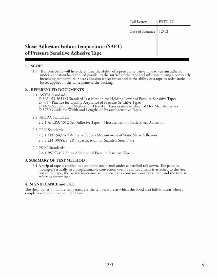
Shear Adhesion Failure Temperature (SAFT)of Pressure Sensitive Adhesive Tape
1. SCOPE1.1 This procedure will help determine the ability of a pressure sensitive tape to remain adhered
under a constant load applied parallel to the surface of the tape and substrate during a constantly increasing temperature. Shear adhesion (shear resistance) is the ability of a tape to resist static forces applied in the same plane as the backing.
2. REFERENCED DOCUMENTS2.1 ASTM Standards:
D 3654/D 3654M Standard Test Method for Holding Power of Pressure-Sensitive TapesD 3715 Practice for Quality Assurance of Pressure-Sensitive TapesD 4498 Standard Test Method for Heat-Fail Temperature in Shear of Hot Melt AdhesivesD 5750 Guide for Width and Lengths of Pressure-Sensitive Tapes
2.2 AFERA Standards:2.2.1 AFERA 5012 Self Adhesive Tapes - Measurement of Static Shear Adhesion
2.3 CEN Standards2.3.1 EN 1943 Self Adhesive Tapes - Measurement of Static Shear Adhesion2.3.2 EN 10088/2, 2R - Specification for Stainless Steel Plate
2.4 PSTC Standards:2.4.1 PSTC-107 Shear Adhesion of Pressure Sensitive Tape
3. SUMMARY OF TEST METHOD3.1 A strip of tape is applied to a standard steel panel under controlled roll down. The panel is
mounted vertically in a programmable convection oven, a standard mass is attached to the free end of the tape, the oven temperature is increased at a constant, controlled rate, and the time to failure is determined.
4. SIGNIFICANCE and USEThe shear adhesion failure temperature is the temperature at which the bond area fails in shear when a sample is subjected to a standard load.
Call Letters
Date of Issuance
PSTC-17
12/12
17-116-8
62
5. APPARATUS5.1 Specimen cutter - The specimen cutter shall hold two single edge razor blades in parallel planes, a
precise distance apart, to form a cutter of exact specimens widths. A cutter 24 mm cutting width shall be available or appropriate alternates which will not cause edge damage.
Note 1 - This width correspond to the primary metric (SI) units described in ASTM D 5750. These so called “modular metric” units are used throughout the world except for Europe. If it is desirable to test slightly different widths (e.g., 25 mm) of specimens per 9.4, this should be noted per 12.5.
Note 2 - There may be several suppliers of this item. See Appendix B.
5.2 Dispensing system, for solvents, such as a wash bottle
5.3 Panel
5.3.1 A panel at least 50 mm long and 50 mm wide and not less than 1.1 mm thickness stainless steel 302 or 304 in accordance with Specification EN 10088/2, 2R having a bright annealed finish. The surface roughness height shall be 50 ± 25 nm arithmetical average deviation from the mean line. At least one panel end shall form a 90˚ angle with the surface. Panels showing stains, discoloration, or many scratches are not acceptable. New panels should be cleaned prior to use as 10.1.2, except with ten washes of the final solvent. Between uses, the panel test surface shall be protected from scratches and contamination, and the panels stored at conditions described in 8.1.
5.4 Roller, mechanically or hand operated
5.4.1 A steel roller 85 ± 2.5 mm, in diameter and 45 ± 1.5 mm in width, covered with rubber approximately 6 mm in thickness, having a Shore scale A durometer hardness of 80 ± 5. The surface shall be a true cylinder void of any convex or concave deviations. The mass of the roller shall be 2 kg ± 0.1 kg.
5.4.2 No part of the apparatus shall increase the pressure of the roller during use. The roller shall move either mechanically or by hand at the rate of 600 ± 20 mm/min.
5.5 Test stands and ancillary apparatus
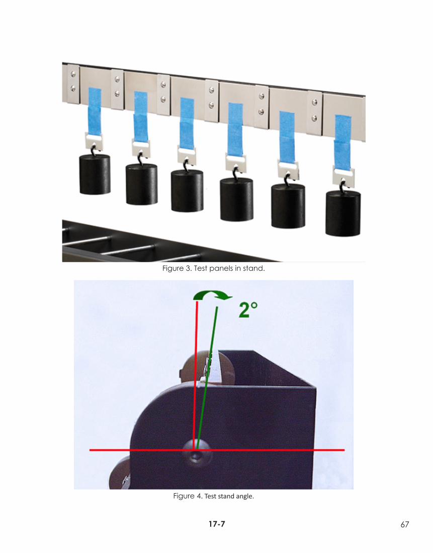
5.5.1 The test stand (see Figure 5), that shall hold the test panel (see Figure 1), with the tape applied, at an angle of 2˚ ± 1˚, (see Figure 4), with the vertical, so that when the mass is acting on the test specimen, no peel forces will be exerted on the tape.
5.5.2 The test stand that will support the test panel in a horizontal plane, approximately 300 mm above the work surface (see Figure 3).
5.5.3 Timers, set to minutes. Clamps (shear clips), that will allow the attachment of the mass to the specimen, distributing the load equally across the tape specimen width.
5.5.4 Test masses5.5.4.1 The test mass (load) shall be 500 ± 2.5 g or 1000 + 5.0 g. The mass of the clamp
described in 5.5.3 shall be included as part of the total mass.
5.5.4.2 Other masses (loads) may be used if mutually agreed upon prior to testing. The mass of the clamp described in 5.5.3 shall be included as part of the total mass.
5.5.5 Timing system
5.5.5.1 Measure the interval between the initiation of the program to the specimens’ separation from the panel to the nearest 0.5 minutes.
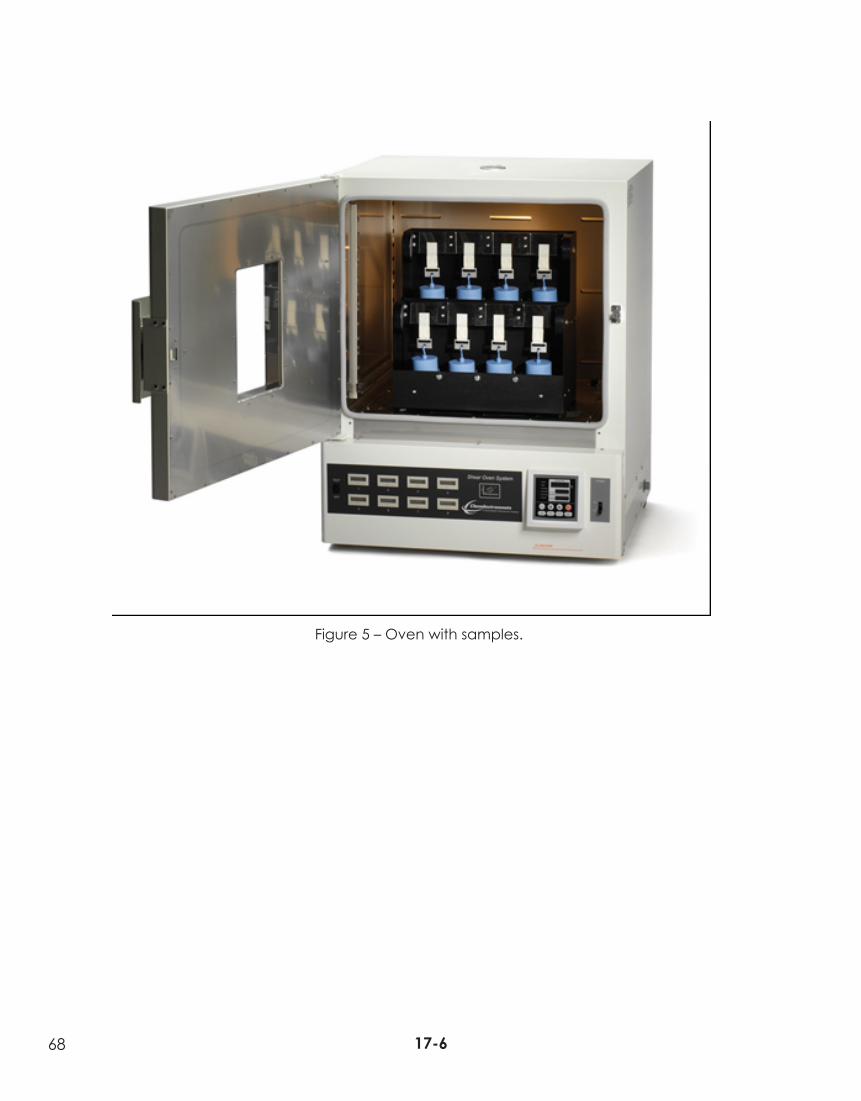
5.6 Oven (see Figure 5)
5.6.1 A programmable forced-ventilation oven capable of maintaining temperature within ± 2°C set point.
5.6.2 The oven must be capable of maintaining a constant temperature increase rate of 30°C/hour over a range of 25 to 200°C.
17-317-2
63
6. REAGENT MATERIALS6.1 Purity of reagents - Reagent grade chemicals should be used in all tests. Other grades may be
used, provided it is first ascertained the reagent is of sufficiently high purity to permit its use without lessening accuracy of the determination.
6.2 Solvents
6.2.1 Any of the following solvents may be used for cleaning:
6.2.1.1 Diacetone alcohol non-residual, technical grade or better
6.2.1.2 Methanol (95%)
6.2.1.3 Methyl Ethyl Ketone (MEK)
6.2.1.4 n-Heptane
6.2.1.5 Acetone
6.2.2 For final cleaning, before each test, MEK or acetone shall be used.
6.3 Cleaning material, absorbent; surgical gauze, cotton wool or tissue. To be suitable, materials must be lint-free during use, absorbent, contain no additives that are soluble in the solvents listed in 6, and made exclusively from virgin materials.
7. SAMPLING
7.1 Sampling shall be in accordance with ASTM Practice D 3715/D 3715M or other formal sampling procedure agreed to by both parties for referee testing. A minimum of three replicate specimens shall be averaged. No single value shall be considered as representative of the roll under test.
8. CONDITIONING8.1 Condition the sample rolls of tape in the standard conditions of 23 ± 1˚ C and 50 ± 5% RH.
Note 3 - Caution: The tester should know that by prolonged handling of the test panel, heat from the hand is transmitted to the test panel. Therefore, just prior to, during, and after application of the specimen to the test panel, the panel should be handled as little as possible.
9. TEST SPECIMENS9.1 Removal from roll
9.1.1 Unwind and discard at least three but no more than six outer wraps of tape from the sample roll before taking specimens for testing.
9.1.2 Remove a minimum of three specimens per sample roll. Remove specimens from freely rotating roll at the rate of 500 to 750 mm/s. Where width or other factor causing a high adherence to backing makes it impossible to remove the specimen at the prescribed rate, remove it at a rate as close to 500 mm/s as possible.
9.2 When tape is wider than specified for in the test method, cut the specimen from the center of the strip removed from the roll in accordance with 9.1.2.
9.3 Apply specimen shortly after unwinding (within 5 minutes).
9.4 Test specimen size.
9.4.1 The test contact area shall be 24 ± 0.5 by 24 ± 0.5 mm. The length of the specimen shall be approximately 150 mm.
17-317-2
64
10. PROCEDURE10.1.1 Program the oven to start at a temperature of 40°C and preheat the oven to that
temperature.
10.1.2 Dispense one of the solvents listed in 6.2.1 onto the panel, wiping to dryness with fresh absorbent cleaning material. Repeat for a total of three washes with this solvent. Final wipe shall be MEK or acetone. Allow the panel to condition for at least 10 minutes prior to applying the test sample. Panels not used within 10 hours should be recleaned.
Note 4 - Discard panels showing stains, discoloration, or many scratches. Avoid contacting panel surface with fingers. During storage, panels should be protected from damage or contamination.
10.1.3 Center the test specimen on one end of the test panel and apply without added pressure to cover an area exactly 24 x 24 mm with the tape, (See Figure 1).
10.1.4 To prevent cutting the specimen by the end of the panel during roll down, place another panel of the same or slightly lesser thickness under the free end of the specimen, and in contact with the end of the panel prior to roll down. Roll down the applied test area twice in each lengthwise direction at a rate of 600 ± 20 mm/min..
10.1.5 Individually prepare each specimen (see Figure 2).
10.1.6 Place the clamp on the masked free end of the specimen, ensuring that the clamp extends completely across the width of the specimen and is aligned to uniformly distribute the load.
10.1.7 Allow 30 ± 2 minutes wet-out (dwell) time prior to hanging the weight.
10.1.8 Place the test assembly in the test stand so that the free end of the test specimen is vertical, ensuring that no peel forces act on the specimen.
10.1.9 Apply the load (500 g or other agreed upon load) gently to the clamp so as not to cause a sudden impact force on the tape specimen. Select the load to apply to the tape based upon the cohesive strength of the tape, e.g., use 500 g for traditional Styrene Block Copolymer (SBC) pressure sensitive adhesives and 1000 g for firmer adhesives such as acrylic pressure sensitive adhesives. If the type of adhesives is unknown, use a 500 g load. If the tape has a SAFT of greater than 205°C, the applied load may be increased and conversely if the SAFT is less than 40°C the applied load may be decreased. Attach the load as rapidly as possible to avoid heat loss but be careful not to apply a sudden impact to the tape specimen.
10.1.10 Zero the timers.
10.1.11 Close the oven door and start timer. Caution: Once oven door is closed, it should not be opened again for the duration of test.
10.1.12 Program the oven to hold temperature at 40°C for 20 minutes and then ramp temperature 30°C/hr (0.5°C/min.). The test ends when all the loads have fallen or the oven’s maximum temperature is reached.
10.1.13 Record the time elapsed until the specimen has completely separated from the test panel.
17-517-4

65
11. CALCULATIONIf the time of failure (t) is 20 minutes or less, the Shear Adhesion Failure Temperature (SAFT) is 40 ˚C.
If the time of failure (t) is greater than 20 minutes and less than 350 minutes, the (SAFT) is calculated using: T = 40 ˚C + ((t -20min)x 0.5 ˚C/min)
Where: t is in minutes and SAFT is in ˚C.
Formula of the above explanation:
≤ 20 minutes < 40°C20 to 350 minutes [(0.5*(time-20)) + 40] °C≥ 350 minutes > 205°C
12. REPORT
12.1 Complete identification of the adhesive tested, if available, including the type, source, manufacturer’s code, lot number, and form in which it was received.
12.2 The surface contact area, if other than 24 mm by 24 mm.12.3 The mass used if other than 500 ± 2.5 g.12.4 The dwell time if other than 30 min.12.5 To the nearest whole °C, the average, standard deviation, number of replicate specimens and the
mode of failure.
SUMMARY OF CHANGES
• This method is published for the first time in the 16th edition.
17-517-4

66
Figure 1. Test panel with sample and weight.
Figure 2. Preparation of the test sample.
17-717-6
67
Figure 3. Test panels in stand.
Figure 4. Test stand angle.
17-717-6
68 21-1
Figure 5 – Oven with samples.
17-6