Embed Size (px)
Citation preview
IMPORTANT SAFETY NOTICE:PARTS MARKED WITH “ ” ( ) AREIMPORTANT FOR MAINTAINING THE SAFETY OF THE SET. BE SURE TO REPLACE THESE PARTS WITH SPECIFIED ONES FOR MAINTAINING THE SAFETY AND PERFORMANCE OF THE SET.
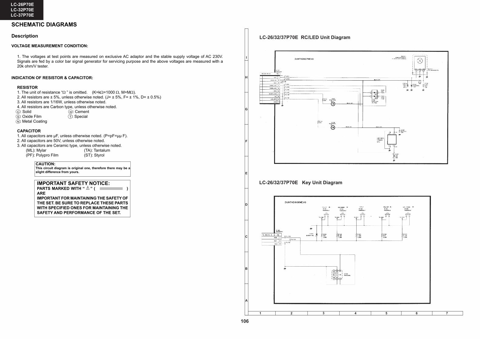
SCHEMATIC DIAGRAMS
Description
VOLTAGE MEASUREMENT CONDITION:
1. The voltages at test points are measured on exclusive AC adaptor and the stable supply voltage of AC 230V. Signals are fed by a color bar signal generator for servicing purpose and the above voltages are measured with a 20k ohm/V tester.
INDICATION OF RESISTOR & CAPACITOR:
RESISTOR1. The unit of resistance “Ω ” is omitted. (K=kΩ=1000 Ω, M=MΩ).2. All resistors are ± 5%, unless otherwise noted. (J= ± 5%, F= ± 1%, D= ± 0.5%)3. All resistors are 1/16W, unless otherwise noted.4. All resistors are Carbon type, unless otherwise noted.C : Solid W : CementS : Oxide Film T : SpecialN : Metal Coating
CAPACITOR1. All capacitors are µF, unless otherwise noted. (P=pF=µµ F).2. All capacitors are 50V, unless otherwise noted.3. All capacitors are Ceramic type, unless otherwise noted. (ML): Mylar (TA): Tantalum (PF): Polypro Film (ST): Styrol
CAUTION:This circuit diagram is original one, therefore there may be a slight difference from yours.
!
1
I
H
G
F
E
D
C
B
A
2 3 4 5 6 7
LC-26/32/37P70E Key Unit Diagram
LC-26/32/37P70E RC/LED Unit Diagram
106
LC-26P70E LC-32P70E LC-37P70E
1 2 3 4 5 6 7 8 9 10 11 12 13 14 15 16
I
H
G
F
E
D
C
B
A
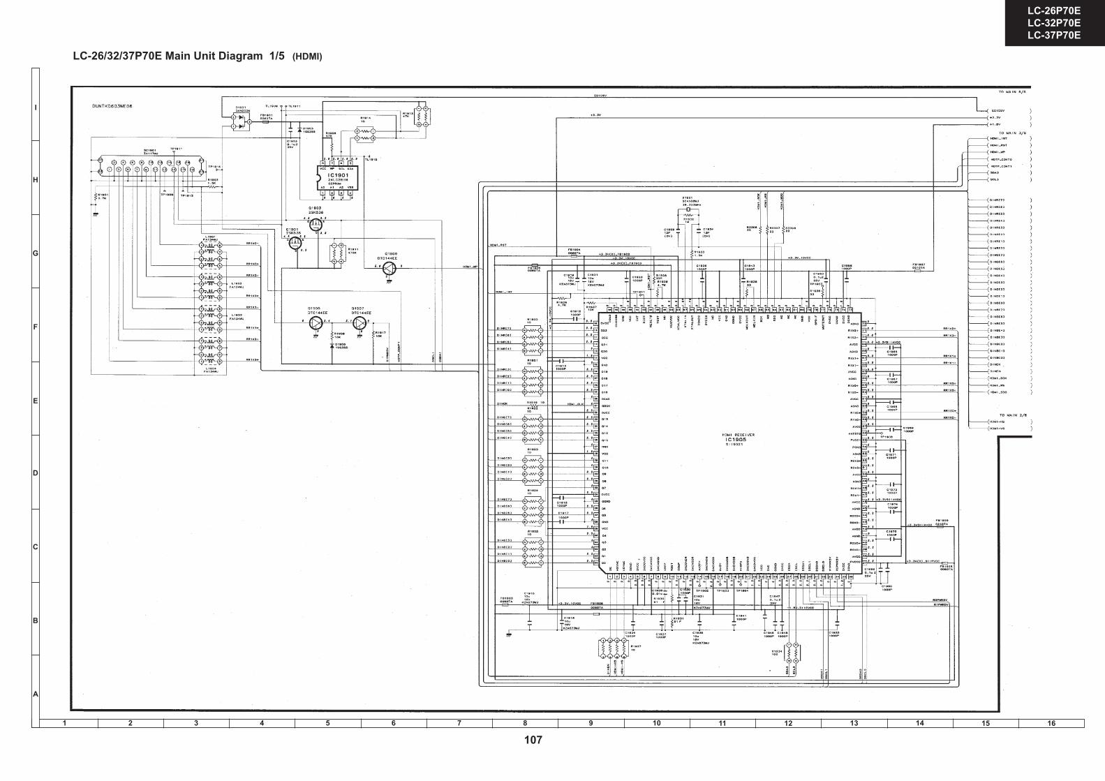
LC-26/32/37P70E Main Unit Diagram 1/5 (HDMI)
107
LC-26P70E LC-32P70E LC-37P70E
1 2 3 4 5 6 7 8 9 10 11 12 13 14 15 16
I
H
G
F
E
D
C
B
A
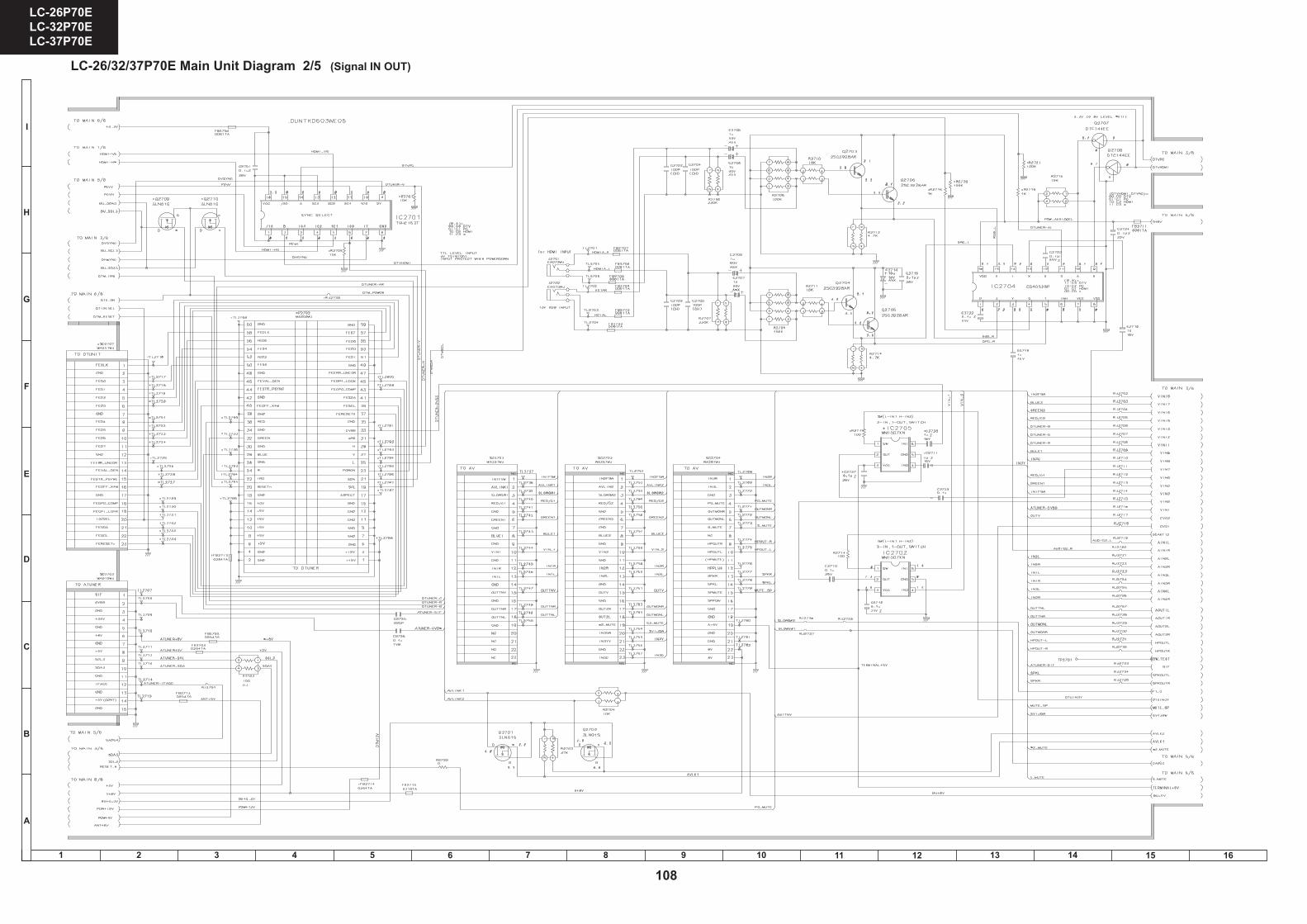
LC-26/32/37P70E Main Unit Diagram 2/5 (Signal IN OUT)
LC-26P70ELC-32P70ELC-37P70E
LC-26P70ELC-32P70ELC-37P70E
87 109654321
A
B
C
D
E
F
G
H
1716 19181514131211
3736
Ë MAIN Unit-2/6
SCHEMATIC DIAGRAM
108
LC-26P70E LC-32P70E LC-37P70E

1 2 3 4 5 6 7 8 9 10 11 12 13 14 15 16
I
H
G
F
E
D
C
B
A
LC-26/32/37P70E Main Unit Diagram 3/5 (VCTP)
109
LC-26P70E LC-32P70E LC-37P70E
1 2 3 4 5 6 7 8 9 10 11 12 13 14 15 16
I
H
G
F
E
D
C
B
A
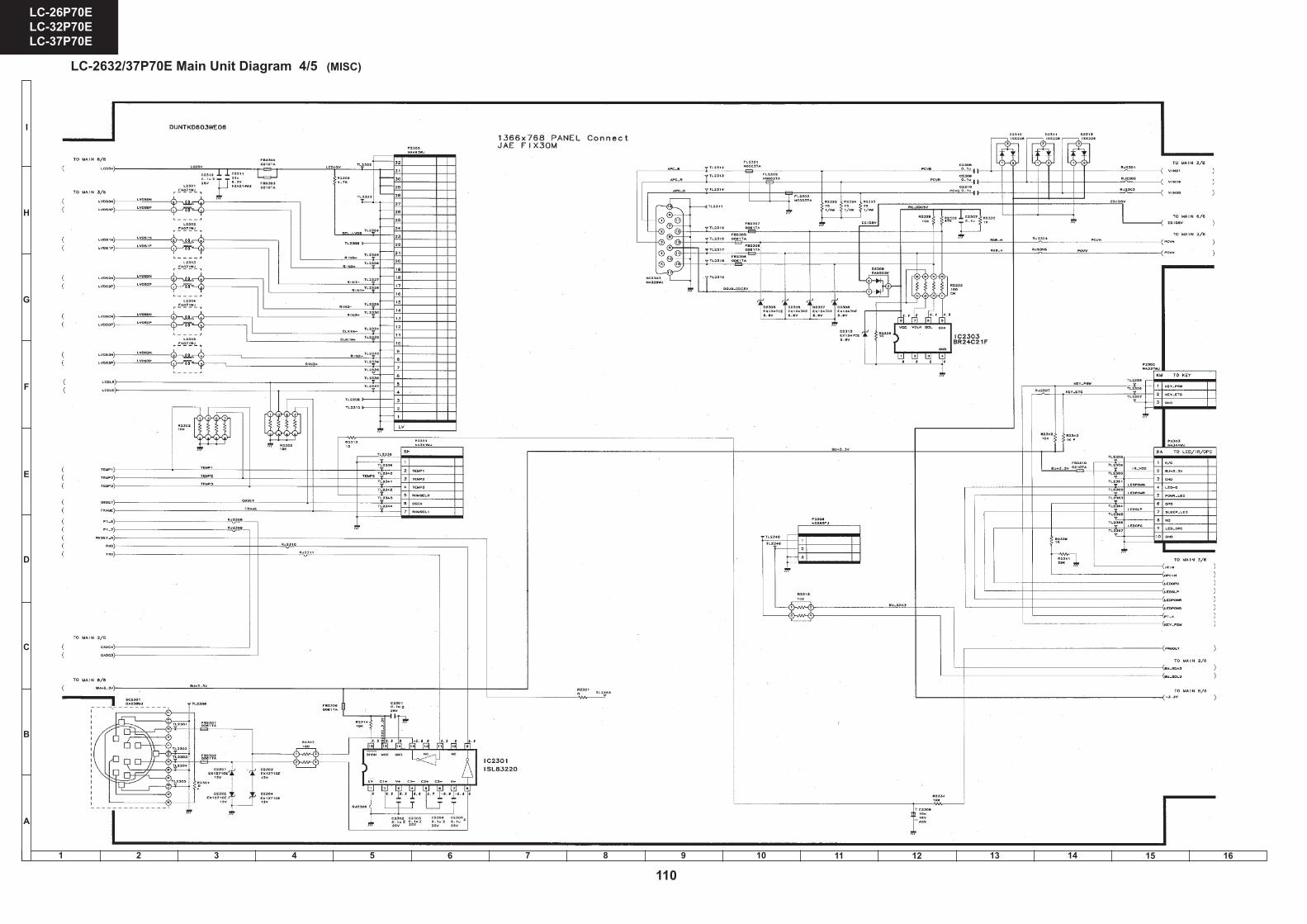
LC-2632/37P70E Main Unit Diagram 4/5 (MISC)
110
LC-26P70E LC-32P70E LC-37P70E
1 2 3 4 5 6 7 8 9 10 11 12 13 14 15 16
I
H
G
F
E
D
C
B
A
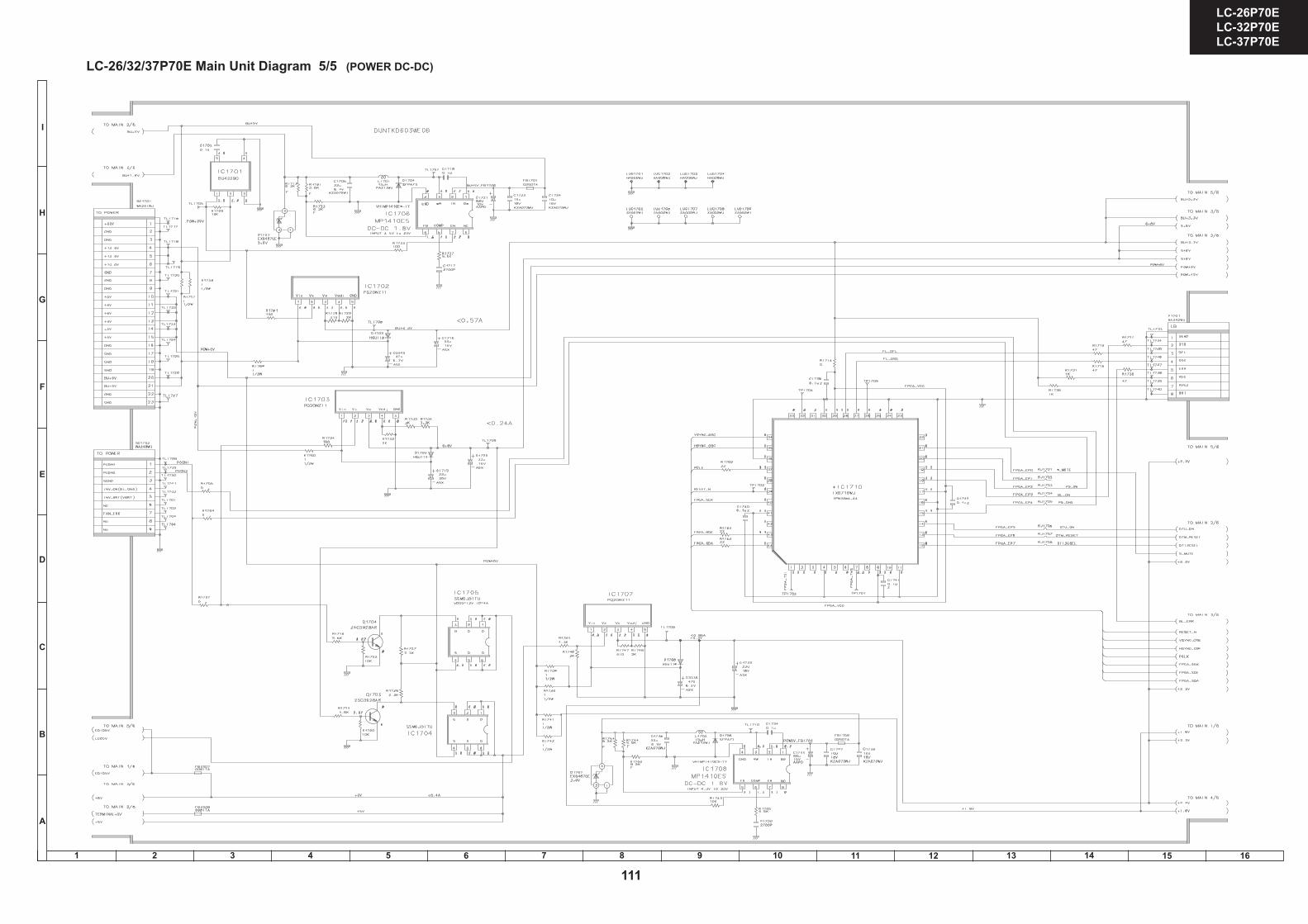
LC-26/32/37P70E Main Unit Diagram 5/5 (POWER DC-DC)
LC-26P70ELC-32P70ELC-37P70E
LC-26P70ELC-32P70ELC-37P70E
87 109654321
A
B
C
D
E
F
G
H
1716 19181514131211
3938
Ë MAIN Unit-6/6
111
LC-26P70E LC-32P70E LC-37P70E
1 2 3 4 5 6 7 8 9 10 11 12 13 14 15 16
I
H
G
F
E
D
C
B
A
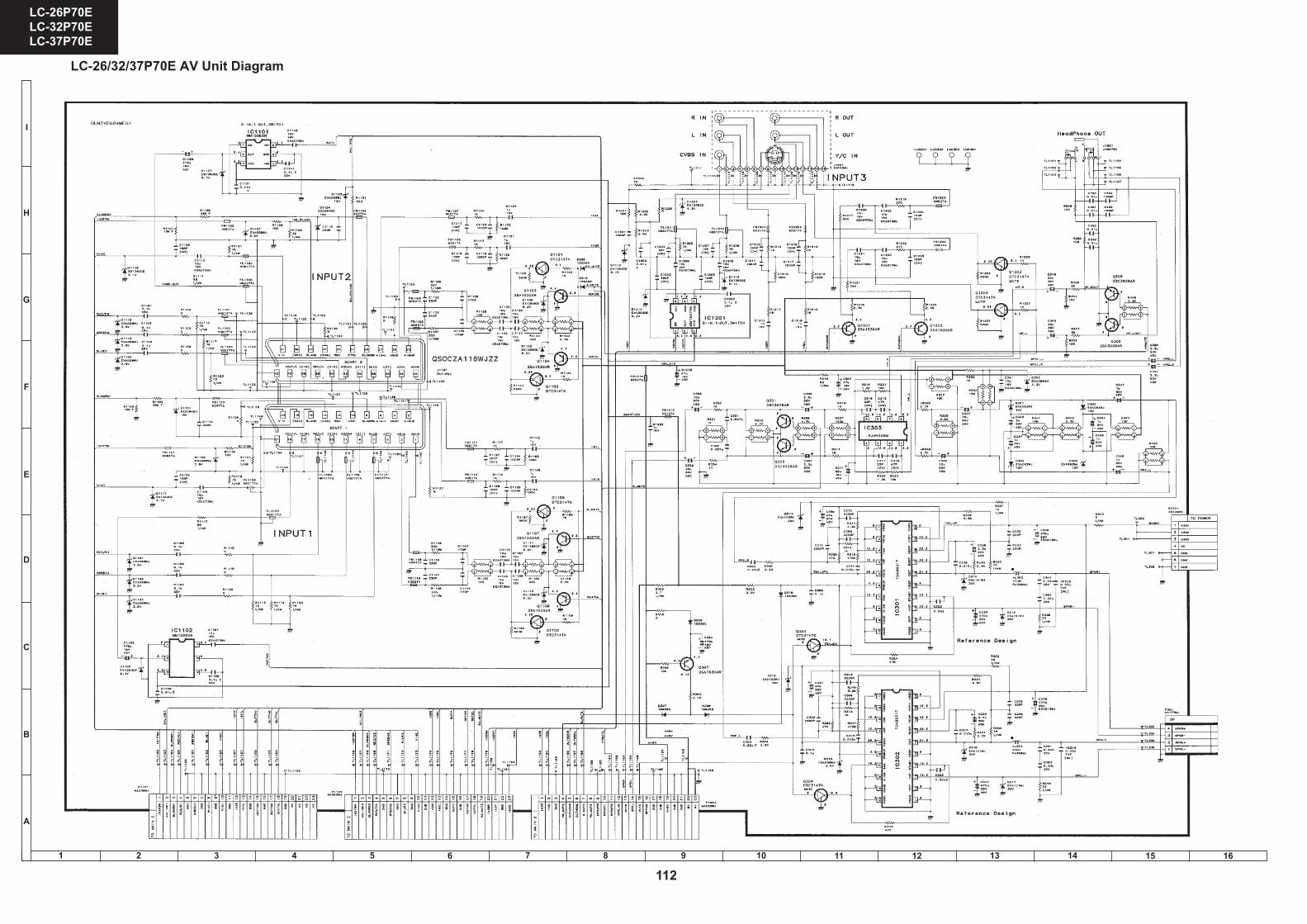
LC-26/32/37P70E AV Unit Diagram
112
LC-26P70E LC-32P70E LC-37P70E
1 2 3 4 5 6 7 8 9 10 11 12 13 14 15 16
I
H
G
F
E
D
C
B
A
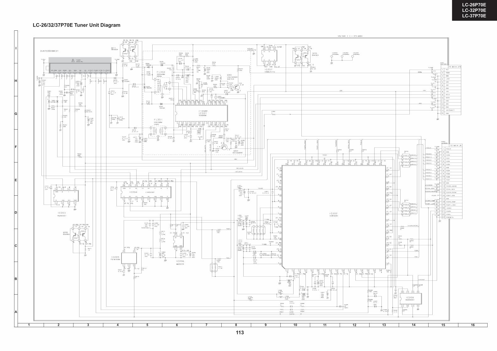
LC-26/32/37P70E Tuner Unit Diagram
LC-26P70ELC-32P70ELC-37P70E
LC-26P70ELC-32P70ELC-37P70E
87 109654321
A
B
C
D
E
F
G
H
1716 19181514131211
4140
Ë TUNER Unit å AND SHADED COMPONENTS=SAFETY RELATED PARTS
113
LC-26P70E LC-32P70E LC-37P70E
1 2 3 4 5 6 7 8 9 10 11 12 13 14 15 16
I
H
G
F
E
D
C
B
A
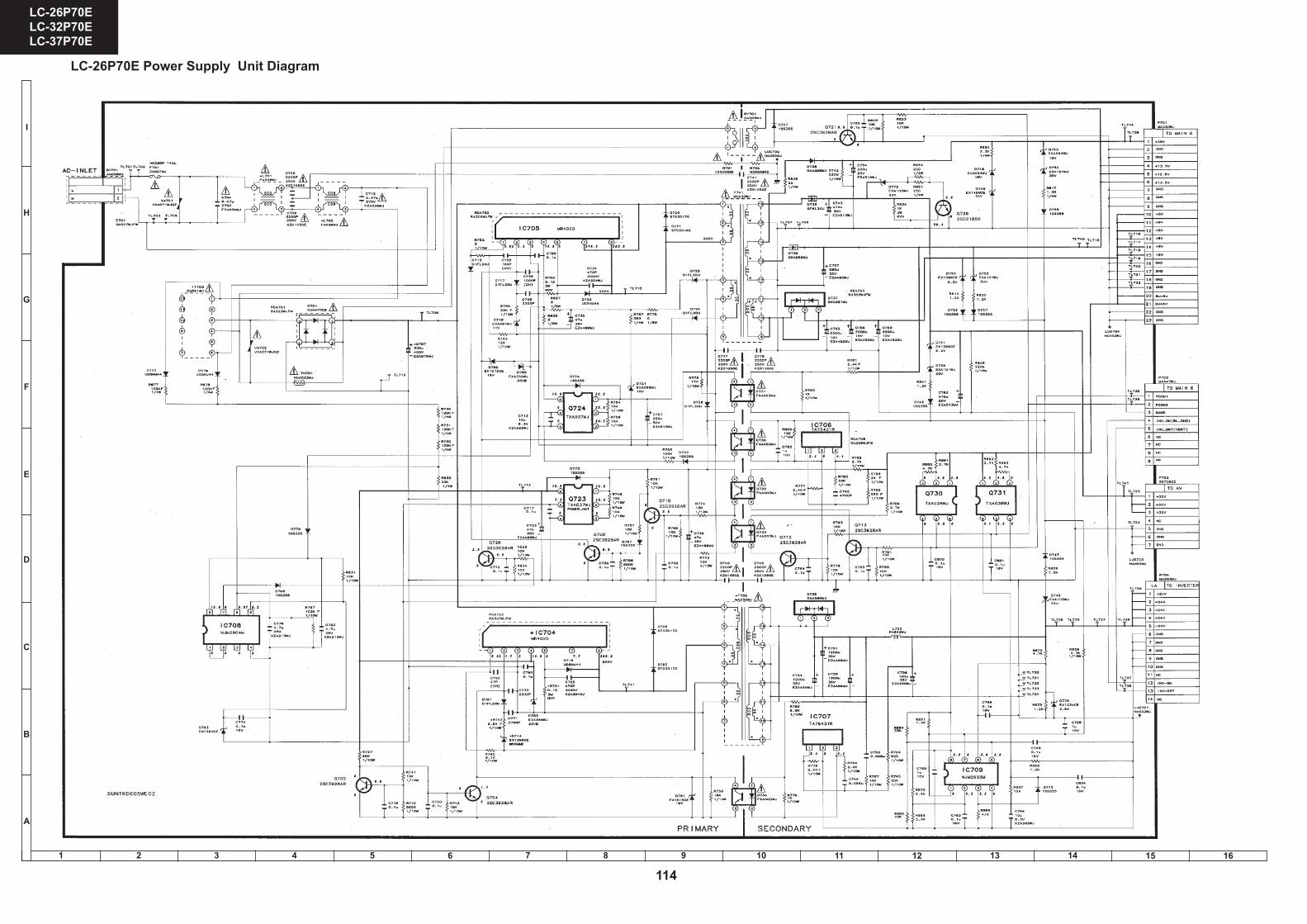
LC-26P70E Power Supply Unit Diagram
114
LC-26P70E LC-32P70E LC-37P70E
1 2 3 4 5 6 7 8 9 10 11 12 13 14 15 16
I
H
G
F
E
D
C
B
A
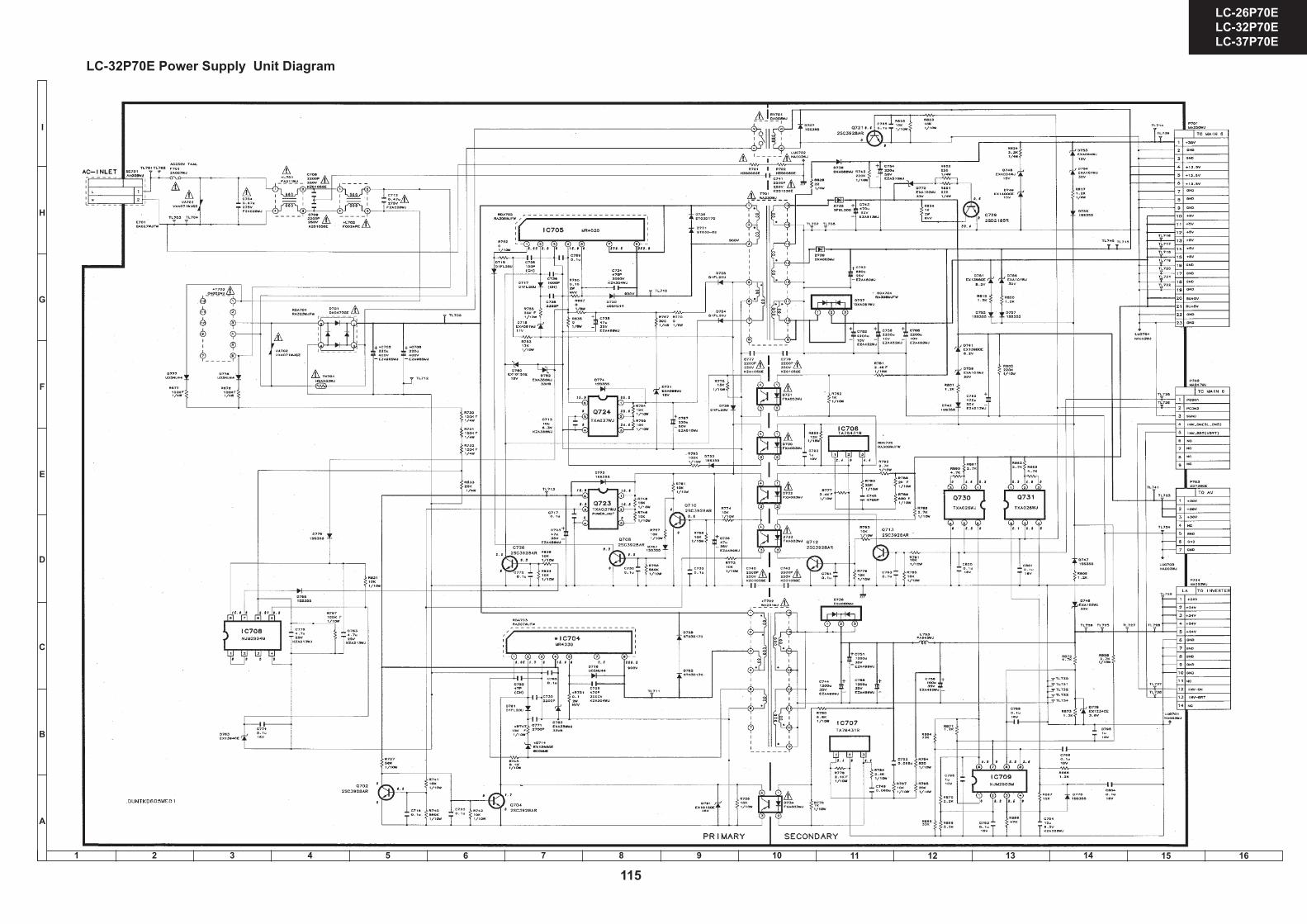
LC-32P70E Power Supply Unit Diagram
115
LC-26P70E LC-32P70E LC-37P70E

1 2 3 4 5 6 7 8 9 10 11 12 13 14 15 16
I
H
G
F
E
D
C
B
A
LC-37P70E Power Supply Unit Diagram
116
LC-26P70E LC-32P70E LC-37P70E

1 2 3 4 5 6 7 8 9 10 11 12 13 14 15 16
I
H
G
F
E
D
C
B
A
LC-26P70E Inverter Unit Diagram (RUNTKA213WJZZ)
117
LC-26P70E LC-32P70E LC-37P70E
1 2 3 4 5 6 7 8 9 10 11 12 13 14 15 16
I
H
G
F
E
D
C
B
A
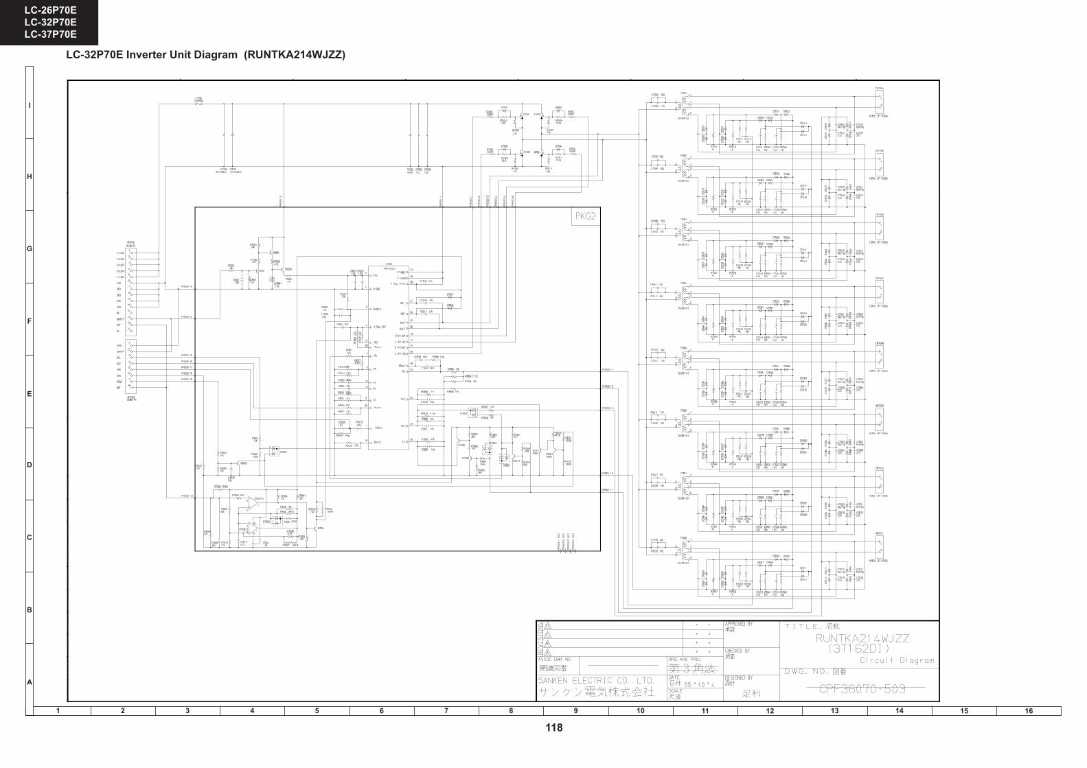
LC-32P70E Inverter Unit Diagram (RUNTKA214WJZZ)
118
LC-26P70E LC-32P70E LC-37P70E

1 2 3 4 5 6 7 8 9 10 11 12 13 14 15 16
I
H
G
F
E
D
C
B
A
LC-37P70E Inverter Unit Diagram (RUNTKA216WJZZ)
119
LC-26P70E LC-32P70E LC-37P70E

1 2 3 4 5 6 7 8 9 10 11 12 13 14 15 16
I
H
G
F
E
D
C
B
A
LC-37P70E Inverter Unit Diagram (RUNTKA217WJZZ)
120
LC-26P70E LC-32P70E LC-37P70E

1 2 3 4 5 6 7 8 9 10 11 12 13 14 15 16
I
H
G
F
E
D
C
B
A
LC-26/32/37P70E Digital Unit Diagram 1/4 (STI5516)
LC-26P70ELC-32P70ELC-37P70E
LC-26P70ELC-32P70ELC-37P70E
87 109654321
A
B
C
D
E
F
G
H
1716 19181514131211
4342
Ë DIGITAL Unit-1/4
121
LC-26P70E LC-32P70E LC-37P70E
1 2 3 4 5 6 7 8 9 10 11 12 13 14 15 16
I
H
G
F
E
D
C
B
A
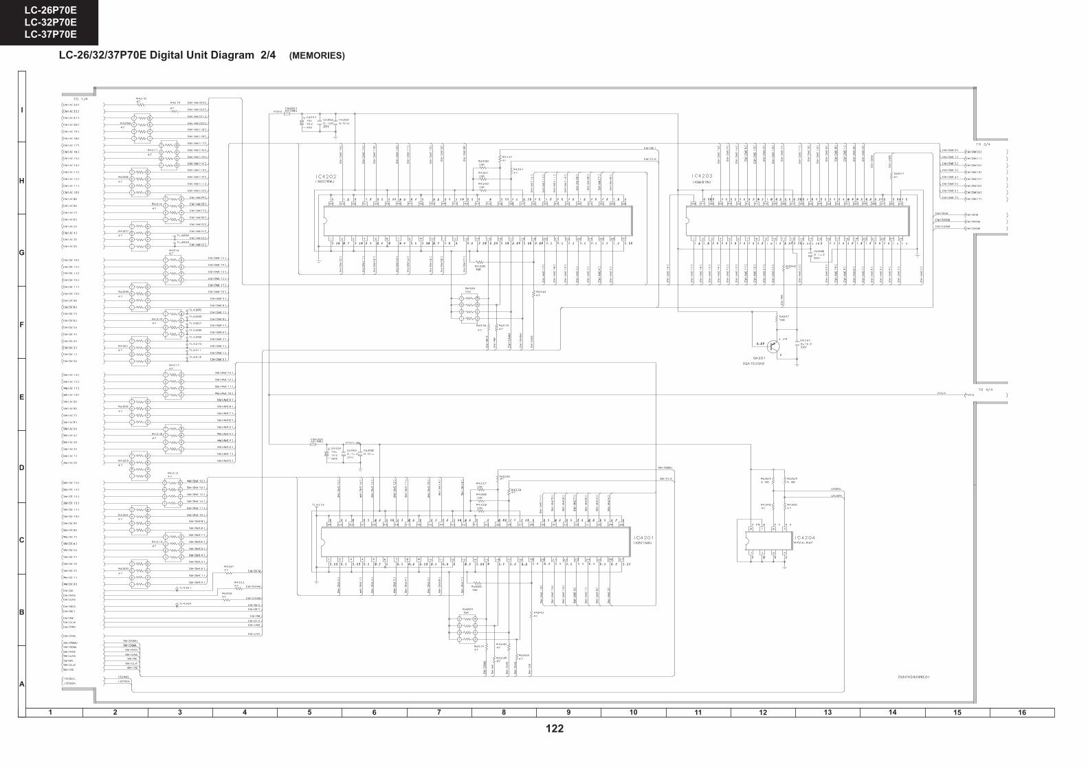
LC-26/32/37P70E Digital Unit Diagram 2/4 (MEMORIES)
LC-26P70ELC-32P70ELC-37P70E
LC-26P70ELC-32P70ELC-37P70E
87 109654321
A
B
C
D
E
F
G
H
1716 19181514131211
4544
Ë DIGITAL Unit-2/4
122
LC-26P70E LC-32P70E LC-37P70E

1 2 3 4 5 6 7 8 9 10 11 12 13 14 15 16
I
H
G
F
E
D
C
B
A
LC-26/32/37P70E Digital Unit Diagram 3/4 (CI)
123
LC-26P70E LC-32P70E LC-37P70E
1 2 3 4 5 6 7 8 9 10 11 12 13 14 15 16
I
H
G
F
E
D
C
B
A
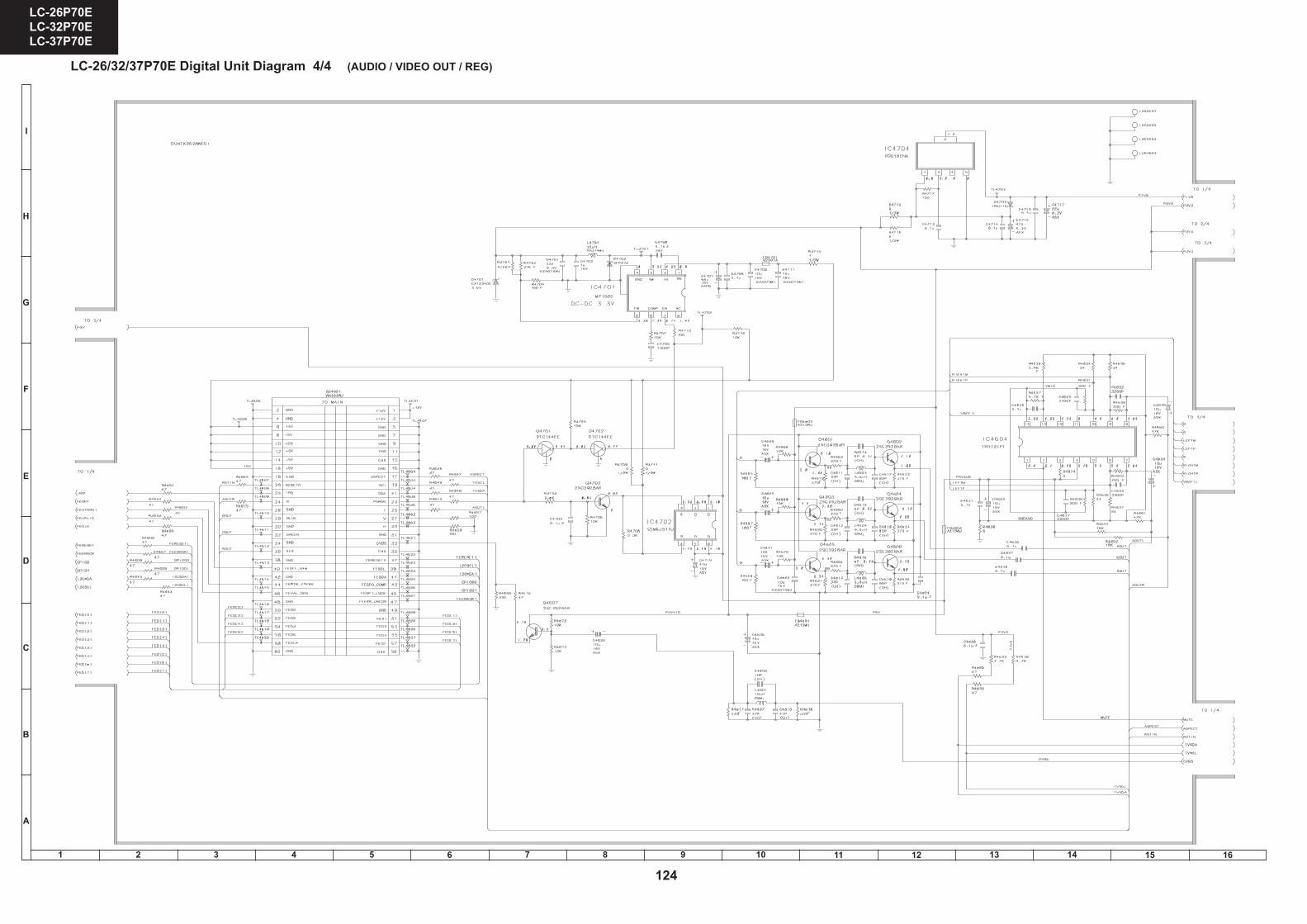
LC-26/32/37P70E Digital Unit Diagram 4/4 (AUDIO / VIDEO OUT / REG)
LC-26P70ELC-32P70ELC-37P70E
LC-26P70ELC-32P70ELC-37P70E
87 109654321
A
B
C
D
E
F
G
H
1716 19181514131211
4948
Ë DIGITAL Unit-4/4
124
LC-26P70E LC-32P70E LC-37P70E

40
LC-26GA5E LC-32GA5E LC-26P70E LC-32P70E LC-37P70E
30
LC-26GA5E LC-32GA5E LC-26P55E LC-32P55E LC-37P55E
TROUBLESHOOTING TABLE
* C705, C706 for 32” and 37”. C707 for 26”.
*
TROUBLESHOOTING TABLE

41
LC-26GA5E LC-32GA5E
LC-26P70E LC-32P70E LC-37P70E
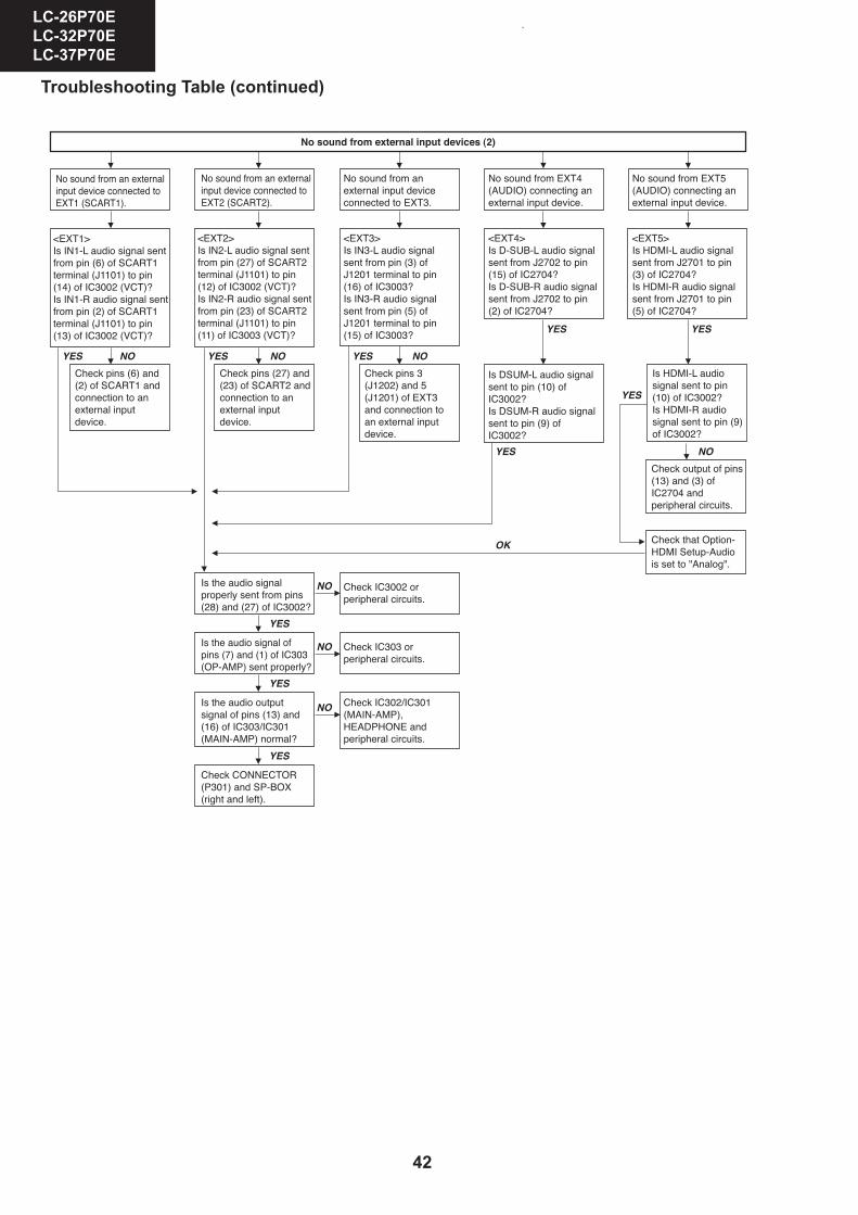
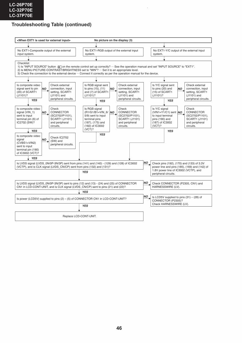
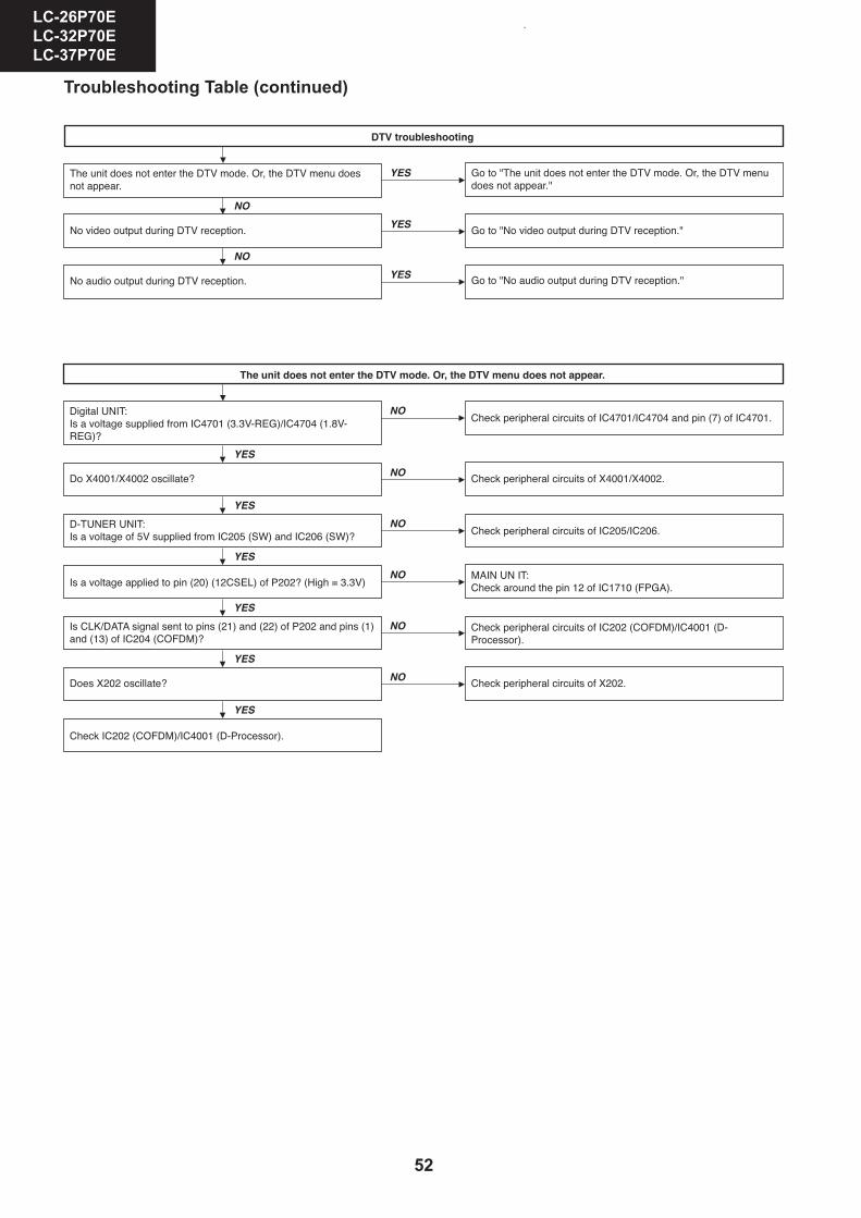
Troubleshooting Table (continued)
LC-26P70ELC-32P70ELC-37P70E
23
TROUBLESHOOTING TABLE
NO
NO
YES
NO
YES
YES
NO
YES
YES
NO
YES
YES
NO
NO
NO
NO
YES
YES
YES
42
LC-26GA5E LC-32GA5E LC-26P70E LC-32P70E LC-37P70E
32
LC-26GA5E LC-32GA5E LC-26P55E LC-32P55E LC-37P55E
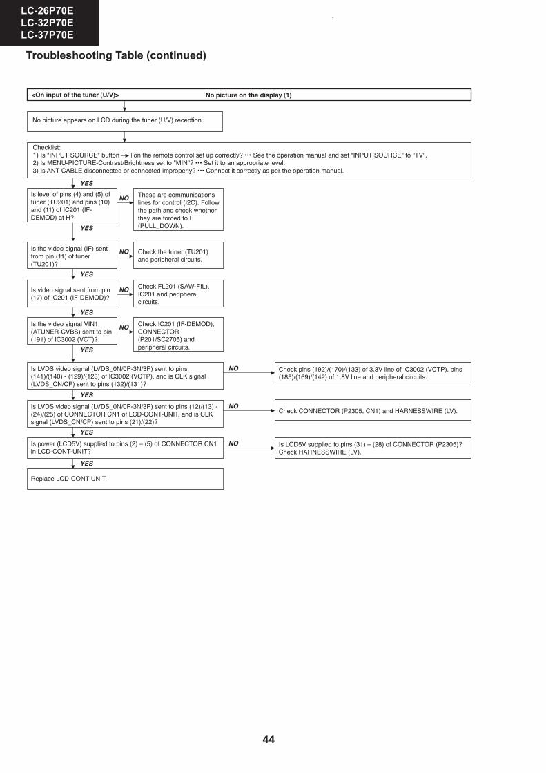
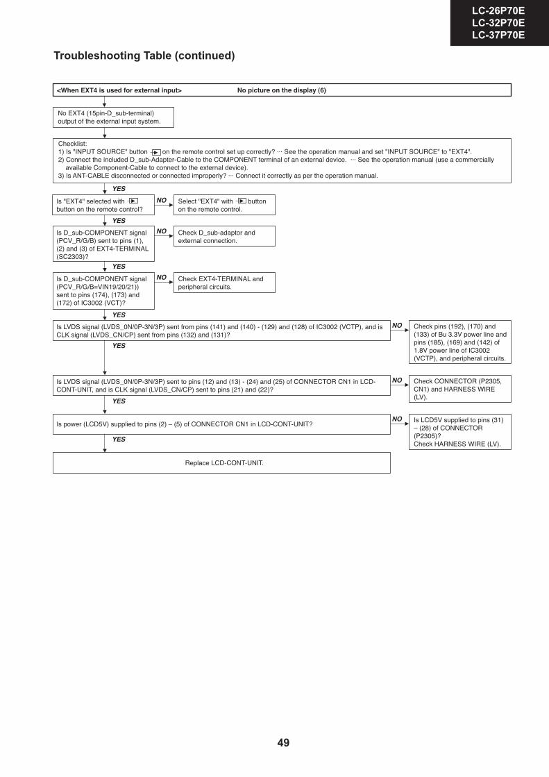
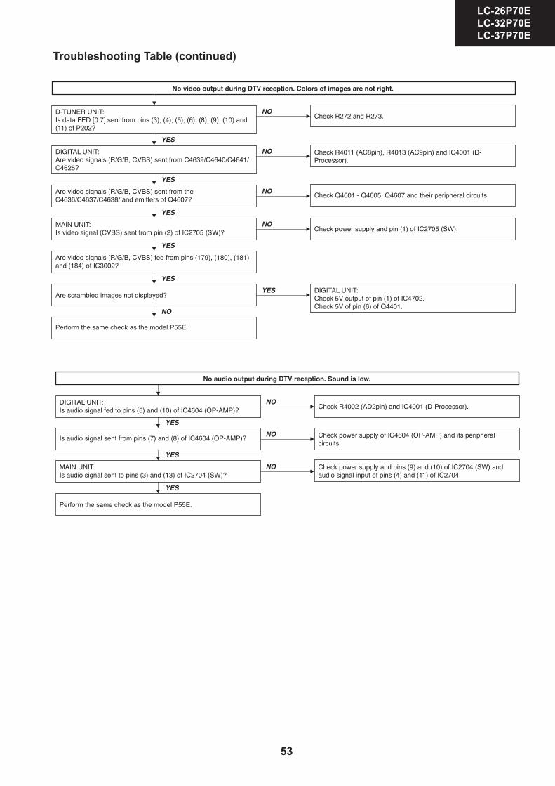
Troubleshooting Table (continued)
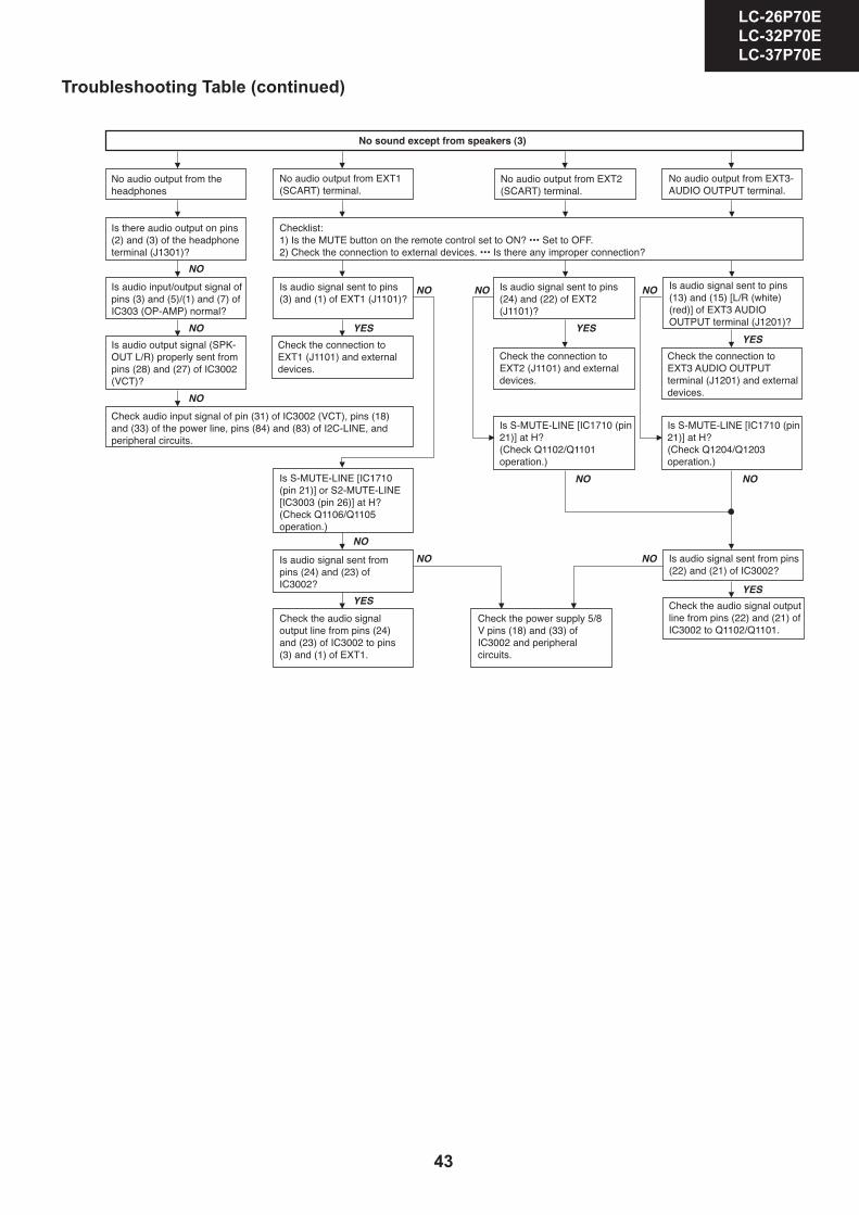
Troubleshooting Table (continued)
43
LC-26GA5E LC-32GA5E
LC-26P70E LC-32P70E LC-37P70E
33
LC-26GA5E LC-32GA5E
LC-26P55E LC-32P55E LC-37P55E
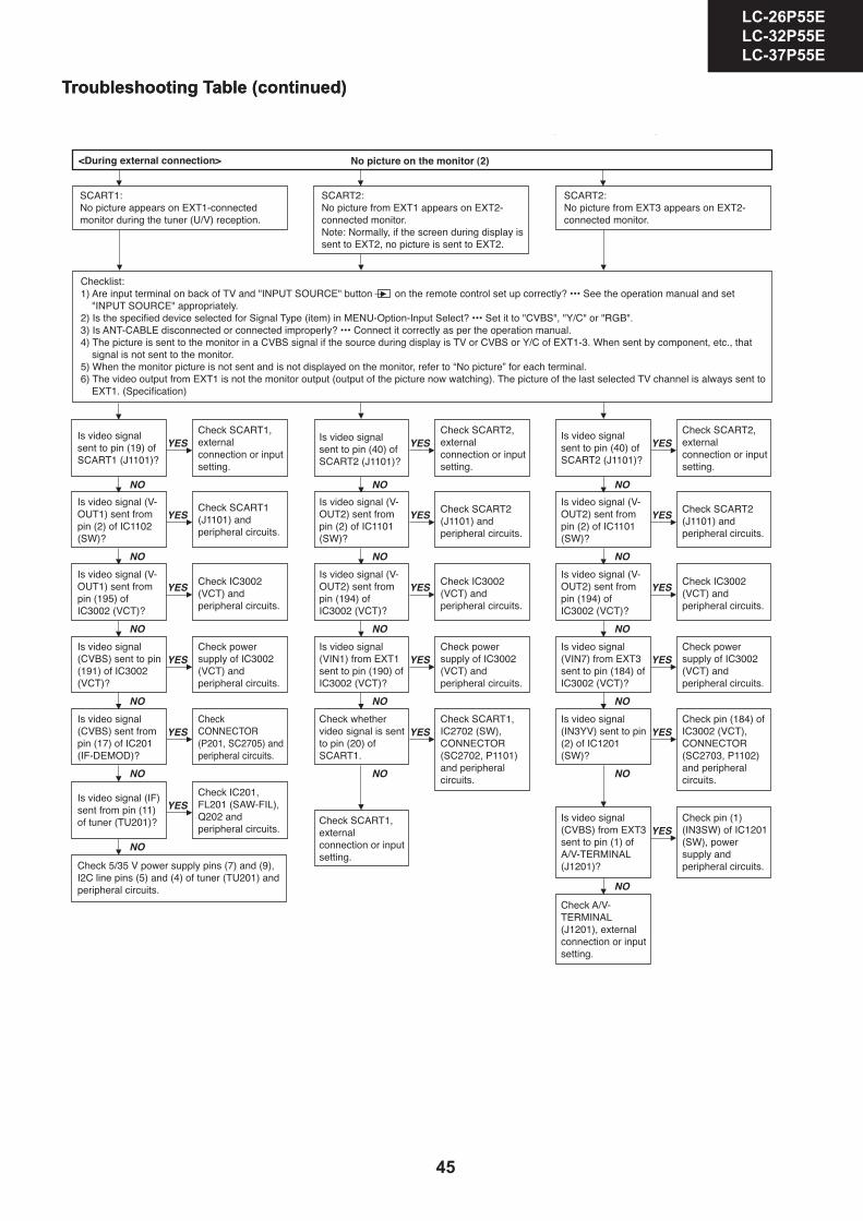
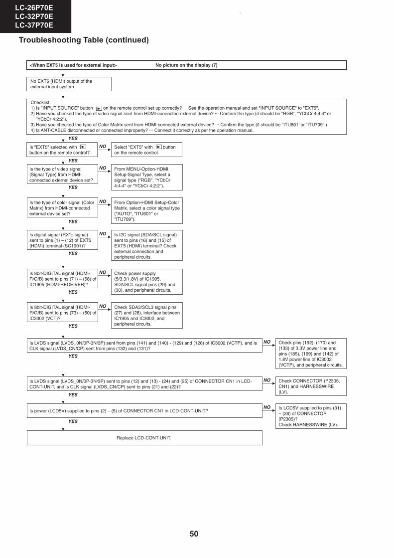
Troubleshooting Table (continued)
Troubleshooting Table (continued)
44
LC-26GA5E LC-32GA5E LC-26P70E LC-32P70E LC-37P70E
34
LC-26GA5E LC-32GA5E LC-26P55E LC-32P55E LC-37P55E
Troubleshooting Table (continued)
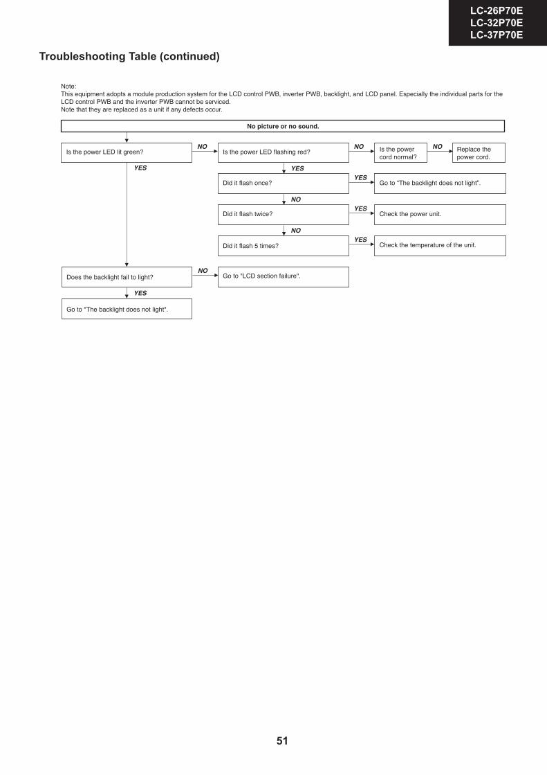
Troubleshooting Table (continued)
45
LC-26GA5E LC-32GA5E
LC-26P70E LC-32P70E LC-37P70E
35
LC-26GA5E LC-32GA5E
LC-26P55E LC-32P55E LC-37P55E
Troubleshooting Table (continued)
Troubleshooting Table (continued)
46
LC-26GA5E LC-32GA5E LC-26P70E LC-32P70E LC-37P70E
36
LC-26GA5E LC-32GA5E LC-26P55E LC-32P55E LC-37P55E
Troubleshooting Table (continued)
Troubleshooting Table (continued)

47
LC-26GA5E LC-32GA5E
LC-26P70E LC-32P70E LC-37P70E
37
LC-26GA5E LC-32GA5E
LC-26P55E LC-32P55E LC-37P55E
Troubleshooting Table (continued)
Troubleshooting Table (continued)

48
LC-26GA5E LC-32GA5E LC-26P70E LC-32P70E LC-37P70E
38
LC-26GA5E LC-32GA5E LC-26P55E LC-32P55E LC-37P55E
Troubleshooting Table (continued)
Troubleshooting Table (continued)
49
LC-26GA5E LC-32GA5E
LC-26P70E LC-32P70E LC-37P70E
Troubleshooting Table (continued)
LC-26P70ELC-32P70ELC-37P70E
26
TROUBLESHOOTING TABLE (Continued)
NO
NO
NO
YES
YES
YES
YES
NO
YES
NO
YES
NO
YES
50
LC-26GA5E LC-32GA5E LC-26P70E LC-32P70E LC-37P70E
40
LC-26GA5E LC-32GA5E LC-26P55E LC-32P55E LC-37P55E
Troubleshooting Table (continued)
Troubleshooting Table (continued)
51
LC-26GA5E LC-32GA5E
LC-26P70E LC-32P70E LC-37P70E
41
LC-26GA5E LC-32GA5E
LC-26P55E LC-32P55E LC-37P55E
Troubleshooting Table (DISPLAY AREA)
Troubleshooting Table (continued)
52
LC-26GA5E LC-32GA5E LC-26P70E LC-32P70E LC-37P70E
Troubleshooting Table (continued)
LC-26P70ELC-32P70ELC-37P70E
24
TROUBLESHOOTING TABLE (Continued)
YES
YES
NO
YES
NO
NO
NO
YES
YES
NO
NO
YES
YES
NO
NO
YES
YES
53
LC-26GA5E LC-32GA5E
LC-26P70E LC-32P70E LC-37P70E
Troubleshooting Table (continued)
LC-26P70ELC-32P70ELC-37P70E
25
TROUBLESHOOTING TABLE (Continued)
NO
YES
NO
NO
YES
YES
NO
YES
NO
NO
YES
YES
NO
NO
YES
YES
YES


