Embed Size (px)
Citation preview

Noname manuscript No.(will be inserted by the editor)
Shape optimization of microstructural designs subject to localstress constraints within an XFEM-level set framework
Lise Noel · Pierre Duysinx
Received: date / Accepted: date
Abstract The present paper investigates the tailor-
ing of bimaterial microstructures minimizing their local
stress field exploiting shape optimization. The prob-
lem formulation relies on the extended finite element
method (XFEM) combined with a level set representa-
tion of the geometry, to deal with complex microstruc-
tures and handle large shape modifications while work-
ing on fixed meshes. The homogenization theory, allow-
ing extracting the behavior of periodic materials built
from the repetition of a representative volume element
(RVE), is applied to impose macroscopic strain fields
and periodic boundary conditions to the RVE. Classical
numerical homogenization techniques are adapted to
the selected XFEM-level set framework. Following pre-
vious works on analytical sensitivity analysis [31], the
scope of the developed approach is extended to tacklethe problem of stress objective or constraint functions.
Finally, the method is illustrated by revisiting 2D clas-
sical shape optimization examples: finding the optimal
shapes of single or multiple inclusions in a microstruc-
ture while minimizing its local stress field.
Keywords Microstructural design · Shape opti-
mization · XFEM · Level set · Stress minimization ·Homogenization
The first author, Lise Noel, is supported by a grant from theBelgian National Fund for Scientific Research (F.R.S.-FNRS)which is gratefully acknowledged.
Lise NoelUniversity of Liege, Aerospace and Mechanics,Allee de la Decouverte, 13A, B52, 4000 LiegeE-mail: [email protected]
Pierre DuysinxUniversity of Liege, Aerospace and Mechanics,Allee de la Decouverte, 13A, B52, 4000 LiegeE-mail: [email protected]
1 Introduction
Nowadays, there is a huge demand for highly efficient
materials to fulfill some particular requirements, even
contradictory ones. In fact, with the development of
the automotive, transport, space. . . industries, the in-
terest in new materials exhibiting extreme properties is
greater than ever. Therefore, many research works are
devoted to the tailoring of material suited for specific
applications. The macroscopic behavior of materials is
related to their microstructures. It follows that design-
ing material at their microstructural level allows ob-
taining prescribed behaviors at the macroscopic level.
In the 1970s, the homogenization theory was devel-
oped to bind the local and global behaviors of materials.
In general, periodic materials are studied, i.e. materialsbuilt from the periodic repetition of a representative
volume element (RVE) in the two (resp. three) direc-
tions of space. Effective macroscopic properties can be
extracted starting from the microstructural specificities
assuming that the RVE scale is very small compared
to the macroscopic one, i.e. there is a clear separation
between these two scales. The theory of homogeniza-
tion is detailed by several authors as Bensoussan et al.
[7], Sanchez-Palencia [35], Suquet [40] or Torquato [43].
Later on, to tackle bigger and more complex microstruc-
tural problems, numerical homogenization methods, re-
sorting to the finite element method (FEM), were de-
veloped. The latter methods are described by Guedes
and Kikuchi [15] or more recently by Andreassen and
Andreasen [3].
Homogenization plays a key role in many engineer-
ing problems. In particular, interaction between homog-
enization theory and topology optimization is rather
important. This interaction is bidirectional. In their
seminal work, Bendsøe and Kikuchi [4] developed an

2 Lise Noel, Pierre Duysinx
approach to provide optimal structural topologies by
searching for an appropriate material distribution over
a given design domain. To circumvent the combinato-
rial problem of presence/absence of material at a point,
they relaxed the problem by introducing porous mate-
rials in the formulation. The effective properties of the
porous periodic microstructure were evaluated using
the homogenization theory. The approach was further
extended by several authors such as Suzuki and Kikuchi
[41] for bending problems or Diaz and Kikuchi [10] for
eigenfrequency maximization. Several microstructural
geometries have been considered for instance square
holes in Bendsøe and Kikuchi [4], rank-N materials in
Bendsøe [6] or Allaire and Kohn [2]. Even if optimal
stiffness properties are obtained as for rank-N materi-
als, there is no consideration of the local stress field
in the microstructures and so no consideration of the
strength of microstructured materials. Reentrant cor-
ners in square holed microstructures and connections
between layers in rank-2 materials, as shown in Fig.(1),
clearly exhibit infinite stresses.
(a) Square holedmicrostructure.
(b) Rank-2 mi-crostructure.
Fig. 1 Microstructures optimized for stiffness and exhibitinginfinite stresses at reentrant corners (1(a)) or at connectionsbetween material layers (1(b)).
On the other way around, optimization has been ex-
tensively used to design material microstructural lay-
outs exhibiting some prescribed macroscopic proper-
ties. The material design problem, known as material
tailoring or inverse homogenization, can be solved ef-
ficiently by resorting to topology optimization tools as
shown by Sigmund [37], [38]. This initial work was later
followed by numerous others considering various objec-
tives: extreme thermal expansion as in Sigmund and
Torquato [39], maximized stiffness as in Guest and Pre-
vost [16] or Weihong et al. [51], extremal bulk modulus
as in Gibiansky and Sigmund [13] or Andreasen et al.
[36]. A review of homogenization and topology opti-
mization is given by Hassani and Hinton [18], [19], [20].
Shape optimization was also exploited to design mate-
rials assuming given parametric geometrical shapes as,
for example, in Zhou et al. [52] or Prochazka and Valek
[33] where the optimal shapes of short fibers maximiz-
ing the bearing capacity of composites were studied.
Extending topology optimization scope to account
for local stress constraints, Duysinx and Bendsøe [12]
assumed that stress constraints could be considered at
the microstructural level by detecting the first point
exceeding the limit resistance of the material. After in-
vestigating the stress level in rank-2 microstructures,
a macroscopic failure model for porous microstructures
was assumed. The corollary of the latter approach is
to investigate layouts and geometries able to minimize
the local stress state in a microstructure for a given
macroscopic stress or strain state. However, despite the
growing number of works on microstructural designs,
local and global stress are scarcely used as objective or
constraint functions.
Early works by Vigdergauz [47], [49], [48] provide
some analytical and numerical solutions for the design
of microstructures of maximal stiffness. Later on, these
results were extended by Grabovsky and Kohn [14] show-
ing that the Vigdergauz microstructure was actually
minimizing the stress concentrations. More recently, Lip-
ton [22] and Lipton and Stuebner [23], [24] provided
some analytical and numerical results for functionally
graded composites and for composite structures under-
going stress constraints. They proposed an inverse ho-
mogenization approach based on the minimization of
some modulation functions connecting the macroscopic
stress to the local stress fluctuations at microscale. More
recently, Najafi et al. [30] also proposed an inverse ho-
mogenization problem to design particulate composites
considering a potential damage in the inclusions using
a NURBS-based shape optimization scheme. They seek
for an appropriate layout of the composite which mini-
mizes the area between the effective stress-strain curve
and a prescribed non linear curve corresponding to a
particular behavior.
The present work aims at contributing to restart
an investigation of the stress state at microstructural
level. In this initial work, we adopt a numerical shape
optimization approach to design bimaterial microstruc-
tures minimizing their local stress fields under given
macroscopic strain state. The level set method is used
to represent the microstructure geometry allowing us
to deal with complex shapes as well as with large shape
modifications. To avoid difficulties related to classical
shape optimization as frequent remeshing operations,
the analysis is carried out on a fixed mesh resorting
to the extended finite element method (XFEM). The
method can handle discontinuities across material in-
terfaces within the elements by adding some enriched
shape functions to the classical FEM approximations.
Exploiting this XFEM-level set framework provides an

Title Suppressed Due to Excessive Length 3
accurate knowledge of the local stress field around the
interfaces and thus a fine control on the local stress. The
sensitivity analysis is performed through an analytical
approach previously developed by Noel et al. [31] and
extended to the evaluation of stress derivatives.
The paper is organized as follow. Section 2 is de-
voted to the optimization framework used through the
paper. The basics of the level set description of the ge-
ometry and the XFEM are recalled. Then, the proce-
dure to evaluate the stress fields is explained. The ho-
mogenization method is briefly exposed in Section 3.
The attention is drawn to the modification in the nu-
merical procedure due to the use of XFEM. The discrete
analytical approach developed to perform the sensitiv-
ity analysis is recalled in Section 4 and the computation
of the stress derivatives is detailed. Finally, Section 5 il-
lustrates the developed methodology on 2D microstruc-
tural designs: finding the optimal shapes and locations
of a single or multiple inclusions in a microstructure
under various loadings.
2 Optimization framework
The objective of this work is to design periodic mi-
crostructures minimizing their local stress field. Two
phase microstructural design problems in two dimen-
sions are considered. A general description of the prob-
lem is given in Fig.(2). Two materials are distributed
over a given RVE, Ω. An interface ΓAB defines the non-
overlapping subdomains ΩA and ΩB filled with mate-
rial A and B respectively. Periodic boundary conditions
are imposed on the RVE as periodic materials are con-
sidered. The RVE is submitted to some equivalent loads
deduced from prescribed macroscopic strain fields.
ΩA
ΩB
Ω
ΓAB
Fig. 2 Description of the microstructural optimization prob-lem.
A bound on the volume V of material phase A or
B is prescribed to avoid trivial solutions. Some extra
constraints gj with j = 1, . . . ,m can also be imposed.
The resulting general optimization problem is for-
mulated as follow:
mins
maxe=1,...,ne
σVM
e (s)
s.t. V (s)− Vmax = 0
gj(s) ≤ 0, j = 1, . . . ,m
si ≤ si ≤ si, i = 1, . . . , n
(1)
where s is a vector collecting the n optimization vari-
ables, σVMe is the Von Mises stress associated to the eth
element of the mesh.
This problem can be reformulated so as to treat the
minimization of the maximum Von Mises stress as sev-
eral stress constraints:
mins
z
s.t. σVMe (s) ≤ z, e = 1, . . . , ne
V (s)− Vmax = 0
gj(s) ≤ 0, j = 1, . . . ,m
si ≤ si ≤ si, i = 1, . . . , n
z ≥ 0
(2)
The optimization problem, proposed in this work,
does not fall into the category of inverse homogeniza-
tion problems. In fact, the homogenization procedure,
as exposed in Section 3, is only exploited to impose pe-
riodic boundary conditions on the RVE and to evaluate
equivalent loads to some prescribed macroscopic strain
fields. The full procedure allowing the extraction of the
effective properties of a given RVE, is only used as a
post-processing operation on the optimization results.
2.1 Level set description of the geometry
In 1988, Osher and Sethian [32] introduced the level
set method to track moving interfaces efficiently. The
method allows the representation of interfaces or dis-
continuities resorting to an implicit function φ of di-
mension n+ 1, while working in a n dimensional space.
An iso-level of this function, generally the iso-zero one,
is chosen to draw the interface or discontinuity and thus
separates the domain between the different materials in
presence. The function φ, known as the level set func-
tion, can be given as a function of the spatial coordi-
nates x and some design parameters s:φ(x, s) > 0, ∀x ∈ ΩAφ(x, s) = 0, ∀x ∈ ΓABφ(x, s) < 0, ∀x ∈ ΩB
. (3)

4 Lise Noel, Pierre Duysinx
where ΩA is the subdomain filled with material A, ΩBthe subdomain filled with material B and ΓAB the in-
terface between the materials A and B.
Implementing FEM on discrete meshes, the level set
function φ is represented by its nodal values φi inter-
polated using classical finite element shape functions
Ni(x):
φh(x, s) =∑i
Ni(x)φi. (4)
In this paper, level set functions are parametrized
using a single or a combination of parametrized geomet-
ric shapes, as circles, ellipses or superellipses. Instead
of evolving the level set function by solving Hamilton-
Jacobi type equations as in Allaire et al. [1] or Wang et
al. [50], the level set function is here expressed as a func-
tion of the design parameters s and is modified through
mathematical programming algorithms. For more de-
tails, the interested reader can refer to van Dijk et al.
[11].
2.2 Extended finite element method
The XFEM was originally developed by Moes et al.
[27] to model crack propagation without remeshing.
The method allows representing singular or discontinu-
ous behaviors within a mesh element by adding specific
shape functions to classical finite element approxima-
tion fields:
uh(x) =∑i∈I
Ni(x) ui +∑i∈I?
N?i (x) ai, (5)
where I is the set of all the mesh nodes, Ni(x) are the
standard finite element shape functions, ui are the de-
grees of freedom (dof) associated to the standard shape
functions Ni(x), I? is the set of enriched nodes, N?i (x)
are the enriched shape functions and ai are the addi-
tional unknowns related to the enrichment.
The desired enrichment is introduced in the approx-
imations resorting to an enrichment function ψ. For
a particular application, the choice of the enrichment
function ψ depends on the singularities or discontinu-
ities that are to be taken into account. In this work,
we focus on interfaces between two materials A and B
characterized by a continuous displacement field, but
a discontinuous strain field. A commonly used enrich-
ment function to represent material interfaces is the
ridge function developed by Moes [26] and given as:
ψ(x) =∑i
Ni(x) |φi| −∣∣∣∣∣∑i
Ni(x) φi
∣∣∣∣∣ . (6)
The additional enriched shape functions N?i (x) are then
built by multiplying the classical finite element shape
functions Ni(x) and the enrichment function ψ(x):
N?i (x) = Ni(x) ψ(x). (7)
Since enriched elements are filled with two differ-
ent materials and present a discontinuity in their strain
field, they have to be treated with special care. The
different techniques implemented to perform the sub-
division and the integration on enriched elements are
briefly recalled hereunder.
2.2.1 XFEM subdivision
The subdivision of the enriched elements is performed
taking advantage of the level set description of the ge-
ometry. The level set function φ is approximated by
a straight line for the sake of simplicity. The intersec-
tions (ξ?, η?) of the iso-zero level curve and the elements
edges are computed, in the 2D case, from the nodal co-
ordinates (ξ1, η1) and (ξ2, η2) and the nodal level set
values φ1 and φ2, as shown in Fig.(3):
ξ? = tξ2 + (1− t)ξ1,η? = tη2 + (1− t)η1,
with t =|φ1|
|φ1|+ |φ2|. (8)
1
2
(ξ1, η1)
(ξ2, η2)
(ξ?, η?)
φ exact
φ approximated
φ1
φ2
Fig. 3 Subdivision of the enriched elements: intersections ofthe iso-zero level set and the edge of an element in 2D.
2.2.2 XFEM integration
To capture the discontinuous strain behavior through
the enriched elements, the integration can no longer be
performed using a classical Gauss quadrature. To ob-
tain accurate results, an integration background mesh
is introduced on the enriched elements. As illustrated
in Figure 4, Gauss points are brought back from a sec-
ond parametric space (m, l) to the first one (ξ, η) where
the classical Gauss quadrature integration is carried out
on each subpart of the parent element independently.
In particular, this procedure is applied to compute the
stiffness matrix K. The elemental stiffness matrix is
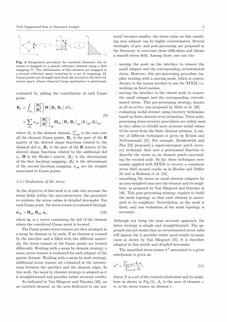
Title Suppressed Due to Excessive Length 5
x
y
1
2
3
4
J1 ξ
η
1 2
34
J2
l
m
Fig. 4 Integration procedure for enriched elements: the el-ement is mapped to a parent reference element using a firstmapping J1. The subdomains of this element are mapped toa second reference space resorting to a set of mappings J2.Gauss points are brought back from the second to the first ref-erence space, where classical Gauss quadrature is performed.
evaluated by adding the contribution of each Gauss
point:
Ke =
∫Ωe
[BTu
BTa
]H[Bu Ba
]dΩe,
'∑gp
wgp
[BTu
BTa
]gp
Hgp
[Bu Ba
]gp|J1|gp |J2|gp ,
(9)
where Ωe is the element domain,∑gp is the sum over
all the element Gauss points, Bu is the part of the B
matrix of the derived shape functions related to the
classical dof ui, Ba is the part of the B matrix of the
derived shape functions related to the additional dof
ai, H is the Hooke’s matrix, |J1| is the determinant
of the first Jacobian mapping, |J2| is the determinant
of the second Jacobian mapping, wgp are the weights
associated to Gauss points.
2.2.3 Evaluation of the stress
As the objective of this work is to take into account the
stress fields within the microstructures, the procedure
to evaluate the stress values is detailed hereunder. For
each Gauss point, the stress tensor is evaluated through:
σgp = Hgp Bgp ue, (10)
where ue is a vector containing the dof of the element
where the considered Gauss point is located.
The Gauss points stress tensors are then arranged as
a mean by element or by node. If an element is crossed
by the interface and is filled with two different materi-
als, the stress tensors at the Gauss points are treated
differently. Working with a mean by element strategy, a
mean stress tensors is evaluated for each subpart of the
parent element. Working with a mean by node strategy,
additional stress tensors are evaluated at the intersec-
tions between the interface and the element edges. In
this work, the mean by element strategy is adopted as it
is straightforward and provides rather accurate results.
As indicated in Van Miegroet and Duysinx [46], on
an enriched element, as the area dedicated to one ma-
terial becomes smaller, the stress value on this vanish-
ing area subpart can be highly overestimated. Several
strategies of pre- and post-processing are proposed in
the literature to overcome these difficulties and obtain
a smooth stress field. Among those, one can cite:
– moving the node on the interface to remove the
small subpart and the corresponding overestimated
stress. However, this pre-processing procedure im-
plies working with a moving mesh, which is contra-
dictory to the reason invoked to use the XFEM, i.e.
working on fixed meshes.
– moving the interface to the closest node to remove
the small subpart and the corresponding overesti-
mated stress. This pre-processing strategy, known
as fit-to-vertex, was proposed by Moes et al. [28].
– evaluating nodal stresses using recovery techniques
based on finite element error estimation. These post-
processing stress recovery procedures are widely used,
as they allow to rebuild more accurate nodal values
of the stress from the finite element solution. A sur-
vey of different techniques is given by Krizek and
Neittaanmaki [21]. For example, Zienkenwick and
Zhu [53] proposed a superconvergent patch recov-
ery technique that uses a polynomial function to
describe the stress on an element patch surround-
ing the treated node. So far, these techniques were
mainly applied with XFEM to recover a consistent
stress field around cracks as in Bordas and Duflot
[8] and in Rodenas et al. [34].
– smoothing the stress on small element subparts by
an area weighted sum over the element and its neigh-
bors, as proposed by Van Miegroet and Duysinx in
[46]. This post-processing strategy requires to build
the mesh topology so that each element is associ-
ated to its neighbors. Nevertheless, as the mesh is
fixed, only one evaluation of the mesh topology is
necessary.
Although not being the most accurate approach, the
latter strategy is simple and straightforward. The ap-
proach can not ensure that no overestimated stress value
will appear but it provides rather good results in many
cases as shown by Van Miegroet [45]. It is therefore
adopted in this article and detailed hereunder.
The smoothed stress tensor σS associated to a given
subelement is given as:
σS =
∑e∈N Aeσe∑e∈N Ae
, (11)
whereN is a set of the treated subelement and its neigh-
bors as shown in Fig.(5), Ae is the area of element e,
σe is the stress tensor on element e.

6 Lise Noel, Pierre Duysinx
Subelement
Neighborhood
Fig. 5 Smoothing the stress field while working with XFEM:neighborhood of a given subelement.
3 Homogenization
As the layout of materials at the microscopic level can
be extremely complex, it is not possible to study these
as a whole. To overcome this difficulty, the theory of ho-
mogenization was developed in the 1970s and allows ex-
tracting effective homogenized properties at the macro-
scopic level. Initial works on homogenization were pro-
vided by Bensoussan et al. [7] and Sanchez-Palencia
[35]. They studied periodic materials built from the rep-
etition of RVEs in two or three dimensions.
In this paper, we focus on orthotropic macroscopic
materials. Their constituent materials are considered as
linear elastic and isotropic. Therefore, the constitutive
equations, at the microscopic scale, are given as follow:
σ = H ε, (12)
where σ is the stress vector, ε the strain vector and H
the Hooke’s matrix.
The homogenized properties of a periodic material
can be deduced from its microstructure as the strain
energy evaluated at the macroscopic level in terms of
macroscopic strains should be equal to the strain energy
calculated from the microscopic strain field. Workingin 2D, the homogenized coefficients HH
ij are obtained
applying three independent unit strain fields εi0:
HHij =
1
Y
∫Y
(εi0 − εi
)TH(εj0 − εj
)TdY,
i, j = 1, . . . , 3,
(13)
where Y is the volume of the RVE, εi0 are the three
prescribed macroscopic strain field (in 2D ε10 = [1 0 0]T ,
ε20 = [0 1 0]T and ε30 = [0 0 1]T ), εi are the local varying
strain fields in the RVE when the latter is submitted to
the unit strain field εi0.
The chosen XFEM-level set framework is used to
extract the equivalent macroscopic properties from the
microstructures, performing numerical homogenization.
The procedure followed in this paper, inspired by works
by Mlejnek and Schirrmacher [25] or more recent similar
works by Andreassen and Andreasen [3], is adapted to
the particular framework.
First, the periodic boundary conditions are applied
through the elimination of redundant dofs. Two corre-
sponding nodes are associated and share the same dofs,
as described in Fig.(6).
u1, v1 u1, v1
u1, v1 u1, v1
u4, v4
u4, v4
u5, v5
u5, v5
u2, v2 u2, v2
u3, v3 u3, v3
Fig. 6 Applying periodic boundary conditions on 2D squareRVE via the elimination of redundant dofs. The nodes areassociated to their corresponding ones: the four corners of thecell are associated and each left (resp. bottom) white (resp.black) node is paired with its corresponding right (resp. top)one. Then, associated nodes share the same dofs.
Then, the displacement field ui, induced in the RVE
by the imposition of the unit strain field εi0, has to be
evaluated. It is done by solving the following equations:
Kui = f i0, i = 1, . . . , 3, (14)
where K is the stiffness matrix of the RVE, ui is the dis-
placement field induced by prescribing the unit strain
field εi0 on the RVE and f i0 is the load vector equivalent
to the application of the unit strain field εi0 on the RVE.
In an XFEM framework, as explained in section
2.2.3, the classical Gauss quadrature can no longer be
applied. The stiffness matrix is then evaluated as in
Eq.(9). The equivalent load vectors f i0 are evaluated as:
f i0 =
∫Y
BT H εi0 dY,
'∑gp
wgp BTgp Hgp εi0 |J1|gp |J2|gp ,
i = 1, . . . , 3.
(15)
Finally, the homogenized coefficients HHij are evalu-
ated through:
HHij =
1
Y
∫Y
(ui0 − ui
)TBTH B
(uj0 − uj
)dY,
=1
Y
(ui0 − ui
)TK(uj0 − uj
),
i, j = 1, . . . , 3.
(16)
where ui0 is the displacement field equivalent to the pre-
scribed unit strain field εi0 and ui is the displacement
field induced by the imposition of the unit strain field
εi0 on the RVE.

Title Suppressed Due to Excessive Length 7
4 Sensitivity analysis
This section focuses on the approach developed to per-
form the sensitivity analysis as proposed in Noel et
al. [31]. Working within an XFEM-level set framework,
performing the sensitivity analysis by finite difference
or a semi-analytical approach can lead to problems and
inaccuracies in the derivatives values. In fact, the per-
turbation of the interface or discontinuity can imply
a change in the status of the elements from enriched
to not enriched and vice versa, resulting in a modifi-
cation of the approximation/discretization fields used
since new shape functions are introduced or retrieved.
Therefore, as suggested in [31], an analytical approach
to the sensitivity analysis can be successfully applied.
4.1 Sensitivity and homogenization
Continuing along previous works, the developed ana-
lytical sensitivity analysis, adapted to the XFEM-level
set framework, is used to evaluate the requested deriva-
tives. Some important features for further developments
are recalled.
Starting from the discretized equations of the linear
elasticity Ku = f , where K is the stiffness matrix, u
the displacements vector and f the vector of the exter-
nal forces, the equations are derived with respect to a
design parameter s, it results:
∂K
∂su + K
du
ds=df
ds⇔ du
ds= −K−1
[∂K
∂su− df
ds
]. (17)
Thus, knowing the derivatives of the stiffness matrix K
and of the vector of the external forces f , the sensitivity
of the displacements vector u can be readily evaluated.
The stiffness matrix derivative is evaluated starting
from its discretized equation and deriving it with re-
spect to a particular design parameter s. Working with
an XFEM-level set framework, one gets:
∂K
∂s=∑gp
w∂BT
∂sH B |J1| |J2|
+∑gp
w BT H∂B
∂s|J1| |J2|
+∑gp
w BT H B |J1|∂ |J2|∂s
.
(18)
The equivalent load vector f0 is dependent on the
design parameters and its derivative is obtained follow-
ing the same procedure. Its discretized expression, given
in Eq.(15) is derived with respect to a particular design
parameter s:
∂f0∂s
=∑gp
w∂BT
∂sH ε0 |J1| |J2|
+∑gp
w BT H ε0 |J1|∂ |J2|∂s
,
i = 1, . . . , 3.
(19)
The derivative of the stiffness matrix, as well as the
derivative of the equivalent load vector, require to eval-
uate the derivatives of the B matrix and of the determi-
nant of the second Jacobian mapping J2 with respect
to the design parameter s.
The B matrix is made of two parts: Bu, related to
the classical dof ui, contains the derivatives of the clas-
sical shape function Ni(x) with respect to (ξ, η) the
coordinates of the first reference space and Ba, related
to the enrichment additional dof ai, contains the deriva-
tives of the enriched shape functionsN?i (x) with respect
to (ξ, η) the coordinates of the first reference space.
The derivative of the Bu matrix with respect to a
design parameter s is built using the following terms:
∂
∂s
∂Ni∂x
∂Ni∂y
= J−11
∂2Ni∂ξ2
∂ξ∂s + ∂2Ni
∂ξ∂η∂η∂s
∂2Ni∂η∂ξ
∂ξ∂s + ∂2Ni
∂η2∂η∂s
. (20)
The derivative of the Ba matrix with respect to a
design parameter s is built using the following terms:
∂∂s
∂N?i∂x
∂N?i∂y
= J−11
∂2Ni∂ξ2
∂ξ∂s + ∂2Ni
∂ξ∂η∂η∂s
∂2Ni∂η2
∂η∂s + ∂2Ni
∂η∂ξ∂ξ∂s
ψ+
∂Ni∂ξ
∂Ni∂η
∂ψ∂s + ∂
∂s
∂ψ∂ξ
∂ψ∂η
Ni+
∂ψ∂ξ
∂ψ∂η
(∂Ni∂ξ
∂ξ∂s + ∂Ni
∂η∂η∂s
) .
(21)
The derivative of the determinant of the second Ja-
cobian mapping J2 with respect to a design parameter
s is given as:
∂|J2|∂s =
(∑i∂Ni∂l
∂ξi∂s
) (∑i∂Ni∂m ηi
)+(∑
i∂Ni∂l ξi
) (∑i∂Ni∂m
∂ηi∂s
)−(∑
i∂Ni∂m
∂ξi∂s
) (∑i∂Ni∂l ηi
)−(∑
i∂Ni∂m ξi
) (∑i∂Ni∂l
∂ηi∂s
).
(22)
As in classical shape optimization, the evaluation of
these derivatives requires the definition and the com-
putation of a velocity field appearing in the equations
8 Lise Noel, Pierre Duysinx
through the following terms: dξ/ds, dη/ds. In classical
shape optimization, the velocity field describes the per-
turbation of the nodal positions with respect to mod-
ifications of the boundaries and has to be evaluated
over the entire design domain. Resorting to an XFEM-
level set framework, a fixed mesh is used and the ve-
locity field describes the material flow through the in-
tersected elements. Therefore, its evaluation is advan-
tageously limited to enriched elements. All the details
about the derivatives involved in these computations
are explained in [31] and the interested reader can refer
to the latter paper to find any additional information.
4.2 Sensitivity of the stresses
The developed analytical sensitivity analysis is also used
to evaluate the derivatives of the stress field.
Starting from Eq.(10) and deriving it with respect
to a design parameter s, one gets:
dσgpds
= Hgp∂Bgp
∂sue + HgpBgp
dueds
, (23)
which only requires the derivatives of the B matrix
given in Eq.(20), Eq.(21) and of the displacements vec-
tor given by Eq.(17).
As pointed out, these derivatives are evaluated di-
rectly from the values extracted during the analysis
and a very small subpart in an element crossed by
the interface can be associated with a highly overes-
timated stress derivative. The latter can lead to con-
vergence problems through the optimization process.
Therefore, the same pre- and post-processing strategies
mentioned in 2.2.3 can be applied. By proceeding this
way, smoothed stress derivative values can be recovered.
5 Applications
The developed approach is illustrated on 2D examples.
It is first validated on a classical shape optimization
problem: a single inclusion in a microstructure under-
going different loadings. In particular, the Vigdergauz
microstructures are investigated as they can achieve ex-
tremal elastic behavior while exhibiting a rather simple
geometry. Later on, the case of microstructures rein-
forced by several stiff inclusions is investigated to illus-
trate that the approach is able to generate more com-
plex microstructural designs.
Optimization problems are formulated as detailed in
Section 2 and solved resorting to mathematical pro-
gramming schemes, as the Method of Moving Asymp-
totes (MMA) of Svanberg [42].
5.1 Single inclusion microstructures under hydrostatic
and shear loadings
As a first example, single inclusion microstructures are
investigated. The design problem aims at finding the
optimal shape of a hole minimizing the surrounding Von
Mises stresses in a square RVE. The material behav-
iors are considered linear elastic and isotropic. Working
with given microscopic material properties and assum-
ing perfect bonding in the case of two-phase composite,
the shape of the hole is the only parameter to deter-
mine the stress field in the microstructure. Therefore,
this problem is well-suited to evaluate the accuracy and
the efficiency of the developed approach. Two loading
cases are considered: a hydrostatic and a pure shear
loading.
5.1.1 Hydrostatic loading
First, a hydrostatic loading is considered: εhydro = [−1−1 0]T . This hydrostatic loading was used as trial loading
while seeking to maximize the effective bulk modulus
of the microstructure and to saturate the correspond-
ing Hashin-Shtrikman bounds [17]. Under hydrostatic
loading and satisfying the traction-free condition on the
hole, Vigdergauz [48] was able to identify the optimal
contour of the hole minimizing the strain energy analyt-
ically. A family of elliptical shapes, evolving from circles
for low hole volume to squares with rounded corners for
higher hole volume, are maximizing the effective bulk
moduli of the material. These shapes also satisfy the
equi-stress principle, i.e. the non zero stresses along the
hole are uniform. Later on, Grabovsky and Kohn [14]
demonstrated that minimizing the strain energy was
equivalent to minimizing the stress concentration in the
case of a single inclusion microstructure undergoing a
single macroscopic load case.
In the following numerical investigations, two dif-
ferent objectives are then pursued and compared: min-
imizing the strain energy C and minimizing the lo-
cal Von Mises stresses σVM. In both cases, the optimal
shape of a hole in a square RVE is sought. The hole is
represented by a superellipse with a prescribed target
volume Vmax. The superelliptical hole is characterized
by two geometric features used as design parameters:
a, its semi-axis length and ξ, its exponent. The hole is
modeled by a very soft material, i.e. Esolid/Esoft = 106.
Proceeding this way, the chosen XFEM approximation
for material interface can be applied directly without
constraining the dofs within the void regions. Both ma-
terials have an isotropic and linear elastic behavior. A

Title Suppressed Due to Excessive Length 9
plane stress state is assumed. The optimization prob-
lems to solve are formulated as follow:
Strain energy: Von Mises stress:
mins
C
s.t. Vhole = Vmax
s ≤ s ≤ s
mins
maxe=1,...,ne
σVM
e
s.t. Vhole = Vmax
s ≤ s ≤ s
(24)
The stress design problem is reformulated as de-
tailed in Eq.(2). The stopping criteria are the relative
variations of the design parameters that have to be
smaller than 10−3. The initial configuration, the im-
posed boundary conditions and the mesh are presented
in Fig.(7). All the parameters used through the opti-
mization process are given in Table 1.
E2
E1
εhydro = [−1 − 1 0]T
Fig. 7 Single inclusion microstructure under hydrostaticloading: description of the problem.
Table 1 Single inclusion microstructure under hydrostaticloading: parameters.
Dimensions [m] c = 10, t = 1
Elastic moduli [N/m2] E1 = 1, E2 = 10−6
Poisson’s ratio [−] ν1 = ν2 = 0.3
Hydrostatic loading [−] εhydro = [−1 − 1 0]T
Bound on Vhole [m3] Vmax = 20, 40, 60, 80
Bounds on design variables [m] 0 ≤ a ≤ 4.9
[−] 1 ≤ ξ ≤ 20
Level set function φ(x, s) =(xa
)ξ+(ya
)ξ − 1
Gauss points per subelement ngp = 7
Convergence criteria ∆a,∆ξ ≤ 10−3
Mesh 100× 100 bilinear Q4
The optimized shapes found for target hole volumes
of 20, 40, 60 and 80 m3 for both objectives are shown
in Fig.(8). As expected, both formulations lead to very
similar results. Moreover, the obtained results are in
good agreement with Vigdergauz numerical results, as
presented in [48]. For growing target hole volumes, ex-
pected behavior is recovered, i.e. optimized shapes evolve
roughly from circular shapes to squares with rounded
corners. Although the local Von Mises stresses are mini-
mized instead of the stress concentration, Fig.(9) shows
that the stress fields around the holes are rather smooth
and that stress concentrations are avoided.
−5−4−3−2−1 0 1 2 3 4 5−5
−4
−3
−2
−1
0
1
2
3
4
5
(a) Strain energy.
−5−4−3−2−1 0 1 2 3 4 5−5
−4
−3
−2
−1
0
1
2
3
4
5
(b) Von Mises stress.
Fig. 8 Single inclusion microstructure under hydrostaticloading: optimized geometries for target volumes of 20, 40,60 and 80 m3.
(a) Vhole = 20 m3. (b) Vhole = 40 m3.
(c) Vhole = 60 m3. (d) Vhole = 80 m3.
Fig. 9 Single inclusion microstructure under hydrostaticloading: smoothed Von Mises stress fields [N/m2] in the senseof Eq.(11) around the optimized holes for target volumes of20, 40, 60 and 80 m3.
To further validate the numerical results, the ef-
fective bulk modulus κH is evaluated for the different
hole volumes. They are compared against the Hashin-
Shtrikman bounds. As the results are very similar for
the strain energy and the stress formulation, only the

10 Lise Noel, Pierre Duysinx
stress designs are considered here. Theoretically, the op-
timized microstructures should maximize the bulk mod-
ulus and saturate the Hashin-Shtrikman upper bound.
In plane elasticity, the effective bulk modulus κH can
be recollected from the homogenized coefficients HHij
and is given as:
κH =EH
2 (1− νH). (25)
For two-phase materials, in the case of plane elastic-
ity and one material being void, the Hashin-Shtrikman
bounds are given as a function of the microstructure
density ρ, the bulk and the shear modulus of the solid
phase κsolid and µsolid [44], [5]:
0 ≤ κHS ≤ ρ κsolid µsolid
(1− ρ) κsolid + µsolid
. (26)
The comparison is summarized in Fig.(10). It clearly
shows that the optimized stress designs are effectively
able to saturate the Hashin-Shtrikman upper bound.
0 0.2 0.4 0.6 0.8 10
0.2
0.4
0.6
0.8
Density ρ
Bulk
modulusκ
κHS
κH
Fig. 10 Single inclusion microstructure under hydrostaticloading: comparison of the bulk modulus obtained numeri-cally κH with the Hashin-Shtrikman bounds κHS .
To emphasize the choice of an initial superelliptical
shape, the performance of the optimized designs is eval-
uated in terms of maximal Von Mises stress achieved
for various initial shapes. In particular, a circle and an
ellipse are considered. For growing hole volumes, the
maximum Von Mises stress for each initial shape is pre-
sented in Table 2. No results are provided for the circle
and the ellipse for a target hole volume of 80 m3 as
such a high volume can not be reached while remain-
ing inside the RVE. For low hole volume, the maximum
Von Mises stress is very similar regardless of the initial
shape. This was expected as the optimal shape is, in
this case, close to a circle. For higher hole volume, the
maximum Von Mises stress is lower when a superellipse
is used as the optimal shape is a square with rounded
corners.
Table 2 Single inclusion microstructure under hydrostaticloading: influence of the initial shape on the maximum VonMises stress achieved.
σVMmax [N/m2] for \ Vmax [m3] 20 40 60 80
Circle 1.871 1.744 1.796 /
Ellipse 1.870 1.744 1.796 /
Superellipse 1.823 1.550 1.374 1.326
5.1.2 Shear loading
In this second case, a pure shear loading is considered:
εshear = [−1 1 0]T . This pure shear loading was used
as trial loading while seeking to maximize the effec-
tive shear modulus of the microstructure and to satu-
rate the corresponding Hashin-Shtrikman bounds. Un-
der pure shear loading, the equi-stress principle is not
applicable anymore. Vigdergauz [48] was only able to
identify an energy minimizing contour of the hole pre-
senting several angular points. The latter allows the non
zero stresses along the hole to change sign while keep-
ing a constant value, i.e. they satisfy the modular equi-
stress principle. These suboptimal shapes correspond to
squares with sharp corners and slightly rounded sides.
As for the hydrostatic loading, two objectives are
pursued and compared: minimizing the strain energy C
and minimizing the local Von Mises stresses σVM. The
optimal shape of a hole in a square RVE is sought, but
the hole is now represented by the intersection of two
superellipses. Six geometric features are used as design
parameters: ai, the horizontal semi-axis lengths, bi the
vertical semi-axis lengths and ξi, the exponents with
i = 1, 2. The hole is modeled by a very soft material, i.e.
Esolid/Esoft = 106. Both materials have an isotropic and
linear elastic behavior. A plane stress state is assumed.
The two optimization problems to solve are formulated
as in Eq.(24). The stress design problem is reformulated
as detailed in Eq.(2). The stopping criteria are the rel-
ative variations of the design parameters that have to
be smaller than 10−3. The initial configuration, the im-
posed boundary conditions and the mesh are presented
in Fig.(11). All the parameters used through the opti-
mization process are given in Table 3.
The optimized shapes found for target hole volumes
of 20, 40, 60 and 80 m3 for both objectives are shown
in Fig.(12). Anew both formulations in strain energy
and stress lead to very similar solutions. The obtained
results are in good agreement with Vigdergauz numeri-
cal results, as exposed in [48]. Figure 13 shows that the

Title Suppressed Due to Excessive Length 11
E2
E1
εshear = [−1 1 0]T
Fig. 11 Single inclusion microstructure under pure shearloading: description of the problem.
Table 3 Single inclusion microstructure under pure shearloading: parameters.
Dimensions [m] c = 10, t = 1
Elastic moduli [N/m2] E1 = 1, E2 = 10−6
Poisson’s ratio [−] ν1 = ν2 = 0.3
Hydrostatic loading [−] εshear = [−1 1 0]T
Bound on Vhole [m3] Vmax = 20, 40, 60, 80
Bounds on design variables [m] 0 ≤ ai ≤ 4.9
[m] 0 ≤ bi ≤ 4.9
[−] 1 ≤ ξi ≤ 20
Level set function φ1(x, s1) =(xa1
)ξ1 +(yb1
)ξ1 − 1
φ2(x, s2) =(xa2
)ξ2 +(yb2
)ξ2 − 1
φglobal(x, s) = φ1(x, s1) ∪ φ2(x, s2)
Gauss points per subelement ngp = 7
Convergence criteria ∆ai,∆bi,∆ξi ≤ 10−3
Mesh 100× 100 bilinear Q4
Von Mises stress fields for the different target volumes
are quite smooth, avoiding stress concentration in the
microstructure.
−5−4−3−2−1 0 1 2 3 4 5−5
−4
−3
−2
−1
0
1
2
3
4
5
(a) Strain energy.
−5−4−3−2−1 0 1 2 3 4 5−5
−4
−3
−2
−1
0
1
2
3
4
5
(b) Von Mises stress.
Fig. 12 Single inclusion microstructure under pure shearloading: optimized geometries for target volumes of 20, 40,60 and 80 m3.
As explained previously, these contours are only sub-
optimal and are unable to saturate the Hashin-Shtrikman
bounds on the shear modulus. Nevertheless, the effec-
tive shear modulus µH is evaluated for the different
(a) Vhole = 20 m3. (b) Vhole = 40 m3.
(c) Vhole = 60 m3. (d) Vhole = 80 m3.
Fig. 13 Single inclusion microstructure under pure shearloading: smoothed Von Mises stress fields [N/m2] in the senseof Eq.(11) around the optimized holes for target volumes of20, 40, 60 and 80 m3 with the objective of minimizing thelocal Von Mises stress.
hole volumes. They are compared against the Hashin-
Shtrikman bounds. Only the stress designs are consid-
ered here. In plane elasticity, the effective shear modu-
lus µH can be recollected from the homogenized coeffi-
cients HHij and is given as:
µH =EH
2 (1 + νH). (27)
For two-phase materials, in the case of plane elastic-
ity and one material being void, the Hashin-Shtrikman
bounds are given as a function of the microstructure
density ρ, the bulk and the shear modulus of the solid
phase κsolid and µsolid [44], [5]:
0 ≤ µH ≤ ρ κsolid µsolid
(1− ρ) (κsolid + 2µsolid) + κsolid
. (28)
The comparison is summarized in Fig.(14). It shows
that the optimized stress designs are suboptimal and so
unable to saturate the Hashin-Shtrikman upper bound.
To further validate the choice of an initial combi-
nation of two superellipses, the performance of the op-
timized designs is evaluated in terms of maximal Von
Mises stress achieved for different initial shapes. As in
the previous example, a circle and an ellipse are con-
sidered. For growing hole volume, the maximum Von
Mises stress for each initial shape is presented in Table
4. No results are provided for the circle and the ellipse
for a target hole volume of 80 m3 as such a high volume
can not be reached while remaining inside the RVE. As

12 Lise Noel, Pierre Duysinx
0 0.2 0.4 0.6 0.8 10
0.1
0.2
0.3
0.4
Density ρ
Shearmodulusµ
µHS
µH
Fig. 14 Single inclusion microstructure under pure shearloading: comparison of the shear modulus obtained numer-ically µH with the Hashin-Shtrikman bounds µHS .
expected, the maximum Von Mises stress is lower when
the combination of two superellipses is used as the op-
timized shape is, in this case, a square with rounded
sides.
Table 4 Single inclusion microstructure under pure shearloading: influence of the initial shape on the maximum VonMises stress achieved.
σVMmax [N/m2] for \ Vmax [m3] 20 40 60 80
Circle 1.203 1.232 1.262 /
Ellipse 1.203 1.232 1.262 /
2 Superellipses 0.798 0.763 0.755 0.767
5.2 Microstructures reinforced by stiff inclusions
In this second example, microstructures reinforced by
several stiff inclusions are investigated. Optimized shapes
and locations of the inclusions are sought to minimize
the local Von Mises stress in the microstructure. This
problem is inspired from the work by Najafi et al. [29].
The inclusions are represented by circular shapes.
Their radii Ri, as well as their locations (Xci, Yci) in the
RVE, are used as design parameters. Overlapping of the
inclusions is prohibited through the imposition of non
penetrating constraints. Several initial configurations of
the microstructure are considered. The inclusions are
embedded in a soft matrix, i.e. Eincl/Ematrix = 100. The
RVE is loaded through a prescribed macroscopic strain
field ε = [2 1 0]T . Both materials are characterized by
an isotropic and linear elastic behavior. A plane stress
state is assumed. The optimization problem to solve,
for nincl inclusions, is formulated as follow:
mins
maxe=1,...,ne
σVM
e
s.t.∑nincl
j=1 Vj − Vmax = 0
Rk +Rl + 0.3− dkl ≤ 0, k, l = 1, . . . , nincl
si ≤ si ≤ si, i = 1, . . . , n
(29)
where dkl is the distance between the kth and the lth
inclusions.
This design problem is reformulated as detailed in
Eq.(2). The stopping criteria are the relative variations
of the design parameters and of the maximum Von
Mises stress that have to be smaller than 10−3. All the
parameters used through the optimization process are
given in Table 5.
Table 5 Multiple stiff inclusions microstructure: parameters.
Dimensions [m] c = 10, t = 1
Elastic moduli [N/m2] Ematrix = 1, Eincl = 100
Poisson’s ratio [−] νmatrix = νincl = 0.3
Hydrostatic loading [−] εshear = [2 1 0]T
Bound on Vincl [m2] Vmax = 20
Bounds on design variables [m] 0.3 ≤ Ri ≤ 2
[m] 2 ≤ Xci, Yci ≤ 8
Gauss points per subelement ngp = 7
Convergence criterion ∆Ri,∆Xci, ∆Yci ≤ 10−3
∆σVMmax ≤ 10−3
Mesh 100× 100 bilinear Q4
The inclusions are considered very stiff compared
to the matrix, i.e. Eincl/Ematrix = 100. Figure 15 shows
the stress field in a microstructure made of five inclu-
sions embedded in a soft matrix. The inclusions are
highly stressed and their inner stress field is rather uni-
form. It results that the variations of the stress field
within the inclusions are small and can be recollected
with accuracy only resorting to very fine meshes. As
the stress field within the inclusions is rather uniform
and as failure is most likely to appear first in the soft
matrix phase, we choose not to consider the stress field
within the inclusions in the optimization process and
the problem aims at minimizing the local Von Mises
stress in the matrix. Therefore, the location of the in-
clusions is driven by the stress concentrations within
the soft matrix.
The Von Mises stress fields for the initial and op-
timized designs around the inclusions are exposed in
Fig.(16). One may remark that the maximum stress
value is lower in the initial design; this is due to the
fact that the initial configurations violate the constraint
imposed on the inclusions volume.
Starting from several initial configurations, the re-
sulting optimized designs can differ. For configurations

Title Suppressed Due to Excessive Length 13
(a) Microstructure stress field.
(b) Matrix stress field. (c) Inclusions stress field.
Fig. 15 Multiple stiff inclusions microstructure: SmoothedVon Mises stress fields [N/m2] for Eincl/Ematrix = 100 andε = [2 1 0]T on a fine 300× 300 Q4 mesh.
1 and 3, where no inclusion initially lies in the cen-
ter of the RVE, final designs are rather similar. For
configurations 2 and 3, where an inclusion initially lies
in the center of the RVE, final designs are also very
close. These designs are different and lead to different
maximal Von Mises stress values. The non penetrating
constraints induce a certain repulsion force between the
inclusions. For designs 1 and 3, this repulsion prevents
the displacement of the inclusions towards the center of
the RVE. For designs 2 and 4, the inclusion lying in the
center of the RVE limits the displacements of the other
inclusions. They only move around the central one.
The convergence of the optimization process in terms
of maximal Von Mises stress is given in Fig.(17) for
the different initial configurations. The performance in
terms of maximal Von Mises stress varies according
to the initial configurations. One should remark that
the objective function value oscillates. This happens as
the objective is very sensitive to slight modifications of
the interface, as small element subparts can be created.
This sensitivity is related to the XFEM approximation
and will be further investigated in future works.
After exhibiting these results, some important re-
marks have to be made:
– the symmetry of the initial configuration has a huge
influence on the optimized designs. Starting from
symmetric initial designs, it is more difficult for the
optimization scheme to modify the position of the
inclusions and so to break the symmetry.
(a) Initial design 1. (b) Optimized design 1.
(c) Initial design 2. (d) Optimized design 2.
(e) Initial design 3. (f) Optimized design 3.
(g) Initial design 4. (h) Optimized design 4.
Fig. 16 Multiple stiff inclusions microstructure: smoothedVon Mises stress fields [N/m2] in the sense of Eq.(11)for initial and optimized designs around the inclusions, forEincl/Ematrix = 100 and ε = [2 1 0]T .
– the ratio between the stiffnesses of the inclusions
and the matrix, Eincl/Ematrix, also plays a role. If
this ratio is high, the inclusions are highly stressed
and present a rather constant stress field. The move-
ments of the inclusions through the optimization
process are mainly driven by the stress field in the
matrix. If the ratio is low, the magnitude of the
stress field within the inclusions is rather close to the

14 Lise Noel, Pierre Duysinx
10 20 30
2
2.5
3
3.5
4
4.5
5
Iterations
σVM
max
(a) Design 1.
20 40 60 80
2
2.5
3
3.5
4
4.5
5
Iterations
σVM
max
(b) Design 2.
10 20 30
2
2.5
3
3.5
4
4.5
5
Iterations
σVM
max
(c) Design 3.
20 40 60 80 100 120
2
2.5
3
3.5
4
4.5
5
Iterations
σVM
max
(d) Design 4.
Fig. 17 Multiple stiff inclusions microstructure: convergencein terms of maximal Von Mises stress for the different initialconfigurations for Eincl/Ematrix = 100 and ε = [2 1 0]T .
one existing in the matrix. This is shown in Fig.(18)
where the same configuration as in Fig.(15) is con-
sidered but for Eincl/Ematrix = 2. The stress field
within the inclusions might then have a larger influ-
ence on their optimal locations.
(a) Microstructure stress field.
(b) Matrix stress field. (c) Inclusions stress field.
Fig. 18 Multiple stiff inclusions microstructure: smoothedVon Mises stress fields [N/m2] for Eincl/Ematrix = 2 and ε =[2 1 0]T on a fine 300× 300 Q4 mesh.
– the symmetry of the loading also influences the op-
timized designs. A symmetric load case combined
with an initial symmetric microstructure can pre-
vent the modifications and movements of the inclu-
sions in the RVE.
Finally, a more general remark is formulated on the
evaluation of the local stress field resorting to homog-
enization procedures. Performing the optimization of
microstructures while considering stress constraints, it
is critical to know whether the chosen homogenization
procedure provides an accurate indication of the strength
of the composite in practice. This issue was recently ad-
dressed by Coelho et al. [9] who investigate whether ho-
mogenization local stress predictions are in agreement
with numerical stress evaluations in composites build
from the repetition of the unit cell in the three direc-
tions of space. Their study suggests that a low scale
factor, i.e. a low number of repetition of the unit cell, is
sufficient to replace the non-homogeneous composite by
the equivalent homogeneous materials. While beyond
the scope of this paper, this issue is of significant im-
portance and should be further investigated in future
works.
6 Conclusions
The present work has provided a flexible and robust
approach to perform shape optimization of bimaterial
microstructures minimizing their local stress field. The
approach is based on a level set representation of the ge-
ometry and an XFEM discretization. While the level set
representation allowed dealing with complex geometries
and handling large shape modifications, the XFEM was
chosen to avoid heavy remeshing operations inherent to
classical shape optimization. Considering periodic ma-
terials built from the repetition of a RVE, the homoge-
nization theory is applied to impose macroscopic strain
fields and periodic boundary conditions to the consid-
ered RVE. Numerical homogenization techniques were
adapted to fit the selected XFEM-level set framework.
To perform shape optimization with stress objectives or
constraints, the scope of the analytical approach to the
sensitivity analysis, developed in previous work by the
authors [31], was extended. The derivatives of the stress
values were evaluated analytically starting from their
discretized expressions and deriving them with respect
to the design parameters. The different terms involved
in the sensitivities were detailed.
Working with geometric features as design param-
eters, the developed approach is illustrated on some
classical 2D shape optimization problems. The shape
of holed microstructures is optimized to minimize the
Von Mises stress field induced by hydrostatic or pure
shear loadings. Results obtained are very similar to the

Title Suppressed Due to Excessive Length 15
Vigdergauz microstructure. The developed approach is
able to tackle multiple inclusions problems to find the
optimal design of a bimaterial microstructure minimiz-
ing its Von Mises stress field.
Ongoing work aims on the one hand, at consider-
ing other strategies to control the local stress field. In
particular, the minimization of stress ratios can be con-
sidered resorting to different failure stresses so as to
simultaneously deal with the stress in the matrix and
in the inclusions. On the other hand, the optimization
problem can be modified to combine the local stress
field control with some restriction on the stiffness. The
design problem would then focus on maximizing the
stiffness while minimizing the local stress field within
the microstructure. To allow a greater freedom in the
design, nodal level set values could be used as design pa-
rameters. Finally, the work should be further extended
to tackle some non linear behaviors of materials within
the microstructure.
Acknowledgements The authors would like to thank E.Andreassen for the help with the homogenization implemen-tation and for providing the code related to [3].
References
1. Allaire, G., Jouve, F., Toader, A.M.: A level-set methodfor shape optimization. Comptes Rendus Mathematique334(12), 1125–1130 (2002)
2. Allaire, G., Kohn, R.V.: Optimal design of minimumcompliance. European Journal of Mechanics A 12, 839–878 (1993)
3. Andreassen, E., Schousboe Andreasen, C.: How to de-termine composite material properties using numericalhomogenization. Computational Materials Science 83,488–495 (2014)
4. Bendsøe, M., Kikuchi, N.: Generating optimal topolo-gies in structural design using a homogenization method.Computer Methods in Applied Mechanics Engineering71, 197–224 (1988)
5. Bendsøe, M., Sigmund, O.: Material interpolationschemes in topology optimization. Archive of AppliedMechanics 69, 635–654 (1999)
6. Bendsøe, M.P.: Optimal shape design as a material dis-tribution problem. Structural Optimization 1, 193–202(1989)
7. Bensoussan, A., Lions, J.L., Papanicolaou, G.: Asymp-totic analysis for periodic structures. North-Holland(1978)
8. Bordas, S., Duflot, M.: Derivative recovery and a poste-riori error estimate for extended finite elements. Com-puter Methods in Applied Mechanics and Engineering196, 3381–3399 (2007)
9. Coelho, P.G., Reis, R.A., Guedes, J.M.: Convergenceanalysis of stress fields to homogenization predictions inoptimal periodic composite design. In: Proceedings of theVII European Congress on Computational Methods inApplied Sciences and Engineering. Crete Island, Greece(2016)
10. Diaz, A.R., Kikuchi, N.: Solutions to shape and topologyeigenvalue optimization problems using a homogenizationmethod. International Journal for Numerical Methods inEngineering 35, 1487–1502 (1992)
11. van Dijk, N.P., Maute, K., Langelaar, M., van Keulen, F.:Level-set methods for structural topology optimization:a review. Structural and Multidisciplinary Optimization48, 437–472 (2013)
12. Duysinx, P., Bendsøe, M.: Topology optimization of con-tinuum structures with local stress constraints. Interna-tional Journal for Numerical Methods in Engineering 43,1453–1478 (1998)
13. Gibiansky, L., Sigmund, O.: Multiphase composites withextremal bulk modulus. Journal of the Mechanics andPhysics of Solids 48, 461–498 (2000)
14. Grabovsky, Y., Kohn, R.V.: Microstructures minimizingthe energy of a two phase elastic composite in two spacedimensions. ii: The vigdergauz microstructure. Journalof the Mechanics and Physics of Solids 43(6), 949–972(1995)
15. Guedes, J.M., Kikuchi, N.: Preprocessing and post-processing for materials based on the homogenizationmethod with adaptive finite element methods. ComputerMethods in Applied Mechanics and Engineering 83, 143–198 (1990)
16. Guest, J., Prevost, J.H.: Optimizing multifunctional ma-terials: Design of microstructures for maximized stiffnessand fluid permeability. International Journal of Solidsand Structures 43, 7028–7047 (2006)
17. Hashin, Z., Shtrikman, S.: A variational approach to thetheory of the elastic behaviour of multiphase materials.Journal of the Mechanics and Physics of Solids 11, 127–140 (1963)
18. Hassani, B., Hinton, E.: A review of homogenization andtopology optimization i–homogenization theory for mediawith periodic structure. Computers and Structures 69,707–717 (1997)
19. Hassani, B., Hinton, E.: A review of homogenization andtopology optimization ii–analytical and numerical solu-tion of homogenization equations. Computers and Struc-tures 69, 719–738 (1998)
20. Hassani, B., Hinton, E.: A review of homogenizationand topology optimization iii–topology optimization us-ing optimality criteria. Computers and Structures 69,739–756 (1998)
21. Krizek, M., Neittaanmaki, P.: On superconvergence tech-niques. Acta Applicandae Mathematicae 9, 175–198(1987)
22. Lipton, R.: Design of functionally graded compositestructures in the presence of stress constraints. Inter-national Journal of Solids and Structures 39, 2575–2586(2002)
23. Lipton, R., Stuebner, M.: Optimization of compositestructures subject to local stress constraints. ComputerMethods in Applied Mechanics and Engineering 196, 66–75 (2006)
24. Lipton, R., Stuebner, M.: Optimal design of compositestructures for strength and stiffness: an inverse homoge-nization approach. Structural and Multidisciplinary Op-timization 33, 351–362 (2007)
25. Mlejnek, H.P., Schirrmacher, R.: An engineer’s approachto optimal material distribution and shape finding. Com-puter Methods in Applied Mechanics and Engineering106(1), 1–26 (1993)
26. Moes, N., Cloirec, M., Cartaud, P., J.-F., R.: A compu-tational approach to handle complex microstructure ge-ometries. Computer Methods in Applied Mechanics andEngineering 192, 3163–3177 (2003)

16 Lise Noel, Pierre Duysinx
27. Moes, N., Dolbow, J., Belytschko, T.: A finite elementmethod for crack growth without remeshing. Interna-tional Journal for Numerical Methods in Engineering 46,131–150 (1999)
28. Moes, N., Gravouil, A., Belytschko, T.: Non-planar 3dcrack growth by the extended finite element and levelsets–part i: Mechanical model. International Journal forNumerical Methods in Engineering 53, 2549–2568 (2002)
29. Najafi, A.R., Safdari, M., Tortorelli, D.A., Geubelle, P.H.:A gradient-based shape optimization scheme using aninterface-enriched generalized fem. Computer Methodsin Applied Mechanics and Engineering 296, 1–17 (2015)
30. Najafi, A.R., Safdari, M., Tortorelli, D.A., Geubelle,P.H.: Material design using a nurbs-based shape op-timization scheme. In: Proceedings of the 57thAIAA/ASCE/AHS/ASC Structures, Structural Dynam-ics, and Materials Conference. San Diego, California(2016)
31. Noel, L., Van Miegroet, L., Duysinx, P.: Analytical sensi-tivity analysis using the extended finite element methodin shape optimization of bimaterial structures. Inter-national Journal for Numerical Methods in Engineering107(8), 669–695 (2016)
32. Osher, S., Sethian, J.A.: Fronts propagating withcurvature-dependent speed: Algorithms based onhamilton-jacobi formulations. Journal of ComputationalPhysics 79(1), 12–49 (1988)
33. Prochazka, P.P., Valek, M.: Shape optimization of fibersin frc. Acta Geodynamica et Geomaterialia 10(1(169)),111–120 (2013)
34. Rodenas, J.J., Gonzalez-Estrada, O.A., Tarancon, J.E.,Fuenmayor, F.J.: A recovery-type error estimator forthe extended finite element method based on singu-lar+smooth stress field splitting. International Jour-nal for Numerical Methods in Engineering 76, 545–571(2008)
35. Sanchez-Palencia, E.: Homogenization method for thestudy of composite media. In: F. Verhulst (ed.) Asymp-totic Analysis II, Lecture Notes in Mathematics, vol. 985,pp. 192–214. Springer Berlin Heidelberg (1983)
36. Schousboe Andreasen, C., Andreassen, E.,Søndergaard Jensen, J., Sigmund, O.: On the real-ization of the bulk modulus bounds for two-phaseviscoelastic composites. Journal of the Mechanics andPhysics of Solids 63, 228–241 (2014)
37. Sigmund, O.: Materials with prescribed constitutive pa-rameters: An inverse homogenization problem. Interna-tional Journal of Solids and Structures 31(17), 2313–2329(1994)
38. Sigmund, O.: Tailoring materials with prescribed elasticproperties. Mechanics of Materials 20, 351–368 (1995)
39. Sigmund, O., Torquato, S.: Design materials with ex-treme thermal expansion using a three-phase topologyoptimization method. Journal of the Mechanics andPhysics of Solids 45(6), 1037–1067 (1997)
40. Suquet, P.: Une methode duale en homogeneisation : ap-plication aux milieux elastiques. Journal de MecaniqueTheorique et Appliquee pp. 79–98 (1982)
41. Suzuki, K., Kikuchi, N.: Homogenization method forshape and topology optimization. Computer Methods inApplied Mechanics and Engineering 93, 291–318 (1991)
42. Svanberg, K.: The method of moving asymptotes–a newmethod for structural optimization. International Jour-nal for Numerical Methods in Engineering 24, 359–373(1987)
43. Torquato, S.: Random Heterogeneous Materi-als/Microstructure and Macroscopic Properties.Springer, New York (2002)
44. Torquato, S., Gibiansky, L.V., Silva, M.J., Gibson, L.:Effective mechanical and transport properties of cellularsolids. International Journal of Mechanical Sciences 40,71–82 (1998)
45. Van Miegroet, L.: Generalized shape optimization usingxfem and level set description. Ph.D. thesis, Universityof Liege, Liege (2012)
46. Van Miegroet, L., Duysinx, P.: Stress concentration mini-mization of 2d filets using x-fem and level set description.Structural and Multidisciplinary Optimization 33(4–5),425–438 (2007)
47. Vigdergauz, S.: Two-dimensional grained composites ofextreme rigidity. ASME Journal of Applied Mechanics61, 390–394 (1994)
48. Vigdergauz, S.: The effective properties of a perforatedelastic plate numerical optimization by genetic algorithm.International Journal of Solids and Structures 38, 8593–8616 (2001)
49. Vigdergauz, S.: Genetic algorithm perspective to identifyenergy optimizing inclusions in an elastic plate. Inter-national Journal of Solids and Structures 38, 6851–6867(2001)
50. Wang, M.Y., Wang, X., Guo, D.: A level set method forstructural topology optimization. Computer Methods inApplied Mechanics and Engineering 192(1-2), 227–246(2003)
51. Weihong, Z., Fengwen, W., Gaoming, D., Shiping, S.:Topology optimal design of material microstructures us-ing strain energy-based method. Chinese Journal of Aero-nautics 20, 320–326 (2007)
52. Zhou, Y., Li, C., Mason, J.J.: Shape optimization of ran-domly oriented short fibers for bone cement reinforce-ments. Materials Science and Engineering: A 393(1–2),374–381 (2005)
53. Zienkiewicz, O.C., Zhu, J.Z.: The superconvergent patchrecovery a posteriori error estimates. part 1: The recoverytechnique. International Journal for Numerical Methodsin Engineering 33, 1331–1364 (1992)