Embed Size (px)
Citation preview
Shape Optimization of Cover Plates
for Retractable Roof Structures
Thomas Buhl∗
Department of Mechanical Engineering, Solid Mechanics
Nils Koppels Alle, Building 404, Technical University of Denmark
DK-2800 Lyngby, Denmark
Frank V. Jensen and Sergio Pellegrino†
Department of Engineering, University of Cambridge
Trumpington Street, Cambridge CB2 1PZ, U.K.Abstract
The optimal shape of cover plates for circular, symmetric retractable roof struc-
tures based on a grid of multi-angulated rods connected by revolute joints is con-
sidered. It is assumed that these cover plates are co-planar, and hence they are
not allowed to overlap in any configuration; they are also required to form a gap
free surface in the closed configuration. Suitable shapes for the plates are found
by formulating an optimization problem based on suitably defined overlap and gap
area functions. The size of the hinges of the bar structure is considered in the op-
timization. To stabilize the optimization convergence various move limit strategies
are tested and a min-max formulation is proposed. The optimization problems are
solved by the method of moving asymptotes and the sensitivities are found by finite
differences. A series of test cases are presented, whose results agree with previously
known solutions, however the generality of the present method makes it suitable to
develop structures of general shape.∗Current address: Risø National Laboratory, Wind Energy Department, Building VEA-118,
P.O. Box 49, Frederiksborgvej 399, DK-4000 Roskilde, Denmark.†Corresponding author: [email protected]
1
1 Introduction
Over the last couple of decades budgets for sporting events and concerts have substantially
increased and the cost of cancellations has also been increasing. In the period from 1988
to 2002 the Wimbledon tennis tournament was extended nine times due to rain and
so finding a way of covering the center court is of considerable importance; however a
permanent enclosure will be unacceptable because the grass playing surface has to be
exposed to the sunlight. To overcome such conflicting requirements, recently a number of
stadia and swimming pools have been built with retractable roofs.
A concept for retractable roof structures was pioneered by Pinero, who developed
deployable structures that can be folded using the principle of the lazy-tong. These
structures consist of a number of pantograph elements, made of straight bars connected
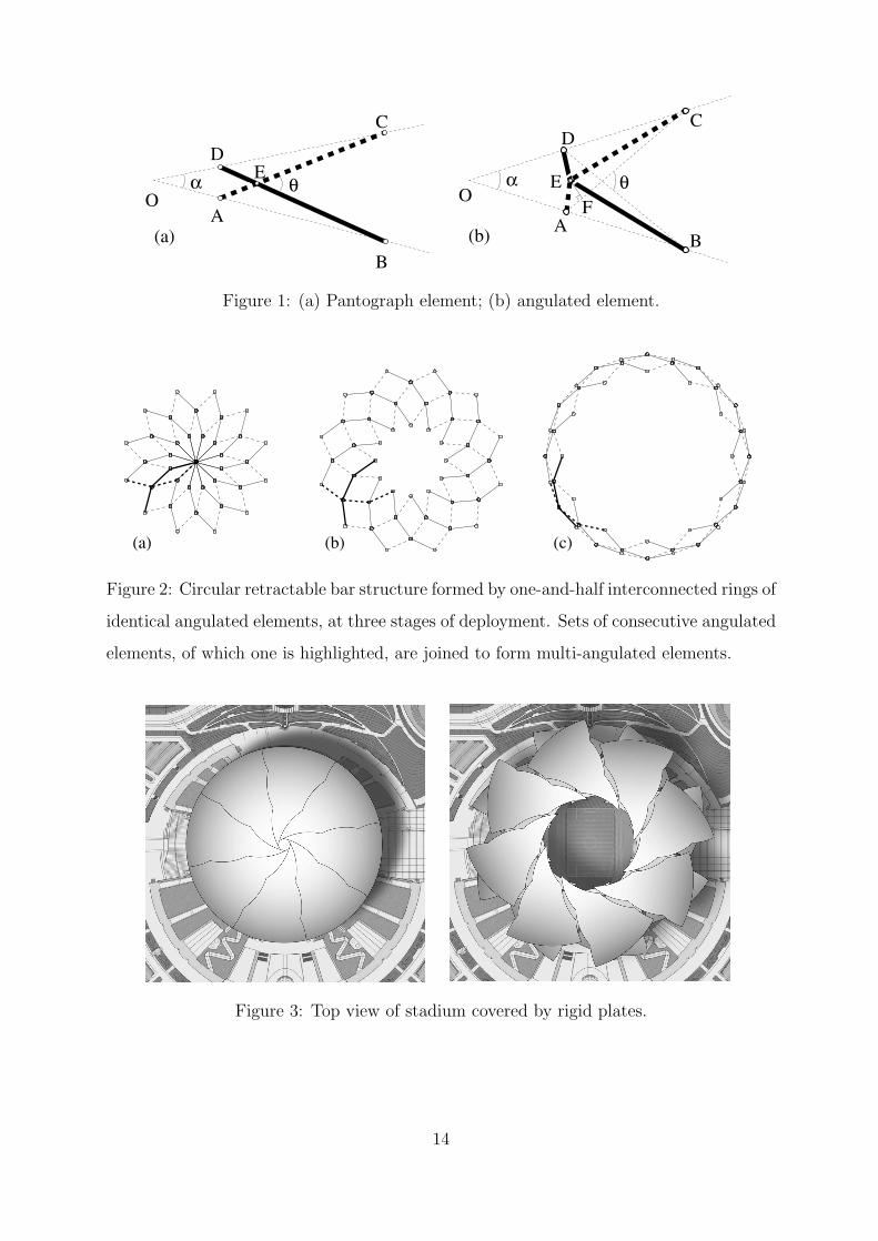
by simple scissor hinges as shown in Figure 1(a) (see e.g. [1], [2], [3]). Deployable bar
structures formed by pantograph elements have the advantage that they can be folded
into a small volume, however they cannot be readily attached to fixed supports which
makes them generally unsuitable for large retractable roofs.
The discovery of the angulated element, shown in Figure 1(b), extended the range
of application of pantograph-type structures. Hoberman’s Iris dome consists of co-axial
rings of angulated elements arranged on conical surfaces, and can expand while remaining
attached to a fixed boundary, [4] and [5]. Multi-angulated elements [6], which consist of
continuous beams with multiple kinks and with hinges at all kink points, as shown in
Figure 2, led to a further extension of this approach, and made it possible to design
structures with many different plan shapes which fold towards the perimeter.
For symmetric, circular structures Reference [7] investigated cover plates that can be
attached to the hinges of multi-angulated bar structures. Some cover plate shapes that
provided a gap-free covering and did not interfere during deployment were proposed. More
general results were later obtained [8], again by heuristic methods, and Figure 3 shows a
concept for a retractable roof cover based on the solution presented in Reference [8]. Note
that any flat structure that satisfies the above conditions can be projected onto a curved
surface, to arrive at a three-dimensional roof structure design [7].
The present paper presents a general study, based on an optimization approach, of the
shapes of cover plates for planar circular retractable structures based on multi-angulated
2
elements, such that there are no overlaps in any configuration (and hence no interference
between the plates) and no gaps in the closed configuration. The physical size of the
hinges, of crucial importance for structures that are to be practically realized, is incor-
porated in the object function. Shapes of plates that maximise the uncovered area when
the structure is in the fully open configuration are obtained. To the authors’ knowledge,
this is the first study of the optimal shape of cover plates for retractable roof structures.
The layout of the paper is as follows. Section 2 discusses the kinematics of retractable
circular structures based on multi-angulated elements. Section 3 formulates the optimiza-
tion problems that are then solved in Section 4 for three different examples. Finally,
Section 5 discusses the results obtained and Section 6 concludes the paper.
2 Foldable Bar Structures
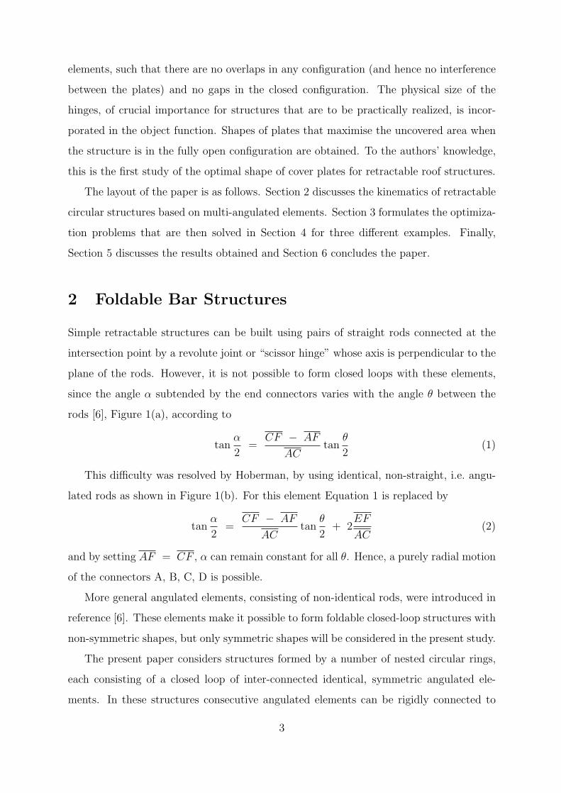
Simple retractable structures can be built using pairs of straight rods connected at the
intersection point by a revolute joint or “scissor hinge” whose axis is perpendicular to the
plane of the rods. However, it is not possible to form closed loops with these elements,
since the angle α subtended by the end connectors varies with the angle θ between the
rods [6], Figure 1(a), according to
tanα
2=
CF − AF
ACtan
θ
2(1)
This difficulty was resolved by Hoberman, by using identical, non-straight, i.e. angu-
lated rods as shown in Figure 1(b). For this element Equation 1 is replaced by
tanα
2=
CF − AF
ACtan
θ
2+ 2
EF
AC(2)
and by setting AF = CF , α can remain constant for all θ. Hence, a purely radial motion
of the connectors A, B, C, D is possible.
More general angulated elements, consisting of non-identical rods, were introduced in
reference [6]. These elements make it possible to form foldable closed-loop structures with
non-symmetric shapes, but only symmetric shapes will be considered in the present study.
The present paper considers structures formed by a number of nested circular rings,
each consisting of a closed loop of inter-connected identical, symmetric angulated ele-
ments. In these structures consecutive angulated elements can be rigidly connected to
3
form multi-angulated elements, i.e. beams made from non-collinear straight pieces, where
the lengths of all pieces are equal and the kink angles are also equal, as shown in Figure 2.
The shape of cover plates that can be used to cover this bar structure will be considered
in the next section.
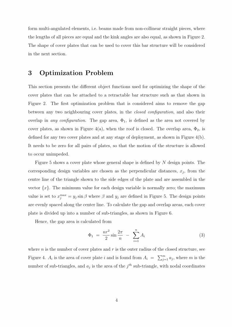
3 Optimization Problem
This section presents the different object functions used for optimizing the shape of the
cover plates that can be attached to a retractable bar structure such as that shown in
Figure 2. The first optimization problem that is considered aims to remove the gap
between any two neighbouring cover plates, in the closed configuration, and also their
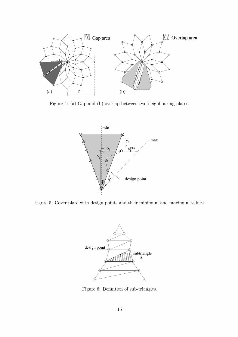
overlap in any configuration. The gap area, Φ1, is defined as the area not covered by
cover plates, as shown in Figure 4(a), when the roof is closed. The overlap area, Φ2, is
defined for any two cover plates and at any stage of deployment, as shown in Figure 4(b).
It needs to be zero for all pairs of plates, so that the motion of the structure is allowed
to occur unimpeded.
Figure 5 shows a cover plate whose general shape is defined by N design points. The
corresponding design variables are chosen as the perpendicular distances, xj, from the
centre line of the triangle shown to the side edges of the plate and are assembled in the
vector {x}. The minimum value for each design variable is normally zero; the maximum
value is set to xmaxj = yj sin β where β and yj are defined in Figure 5. The design points
are evenly spaced along the center line. To calculate the gap and overlap areas, each cover
plate is divided up into a number of sub-triangles, as shown in Figure 6.
Hence, the gap area is calculated from
Φ1 =nr2
2sin
2πn
−n∑
i=1
Ai (3)
where n is the number of cover plates and r is the outer radius of the closed structure, see
Figure 4. Ai is the area of cover plate i and is found from Ai =∑m
j=1 aj, where m is the
number of sub-triangles, and aj is the area of the jth sub-triangle, with nodal coordinates
4
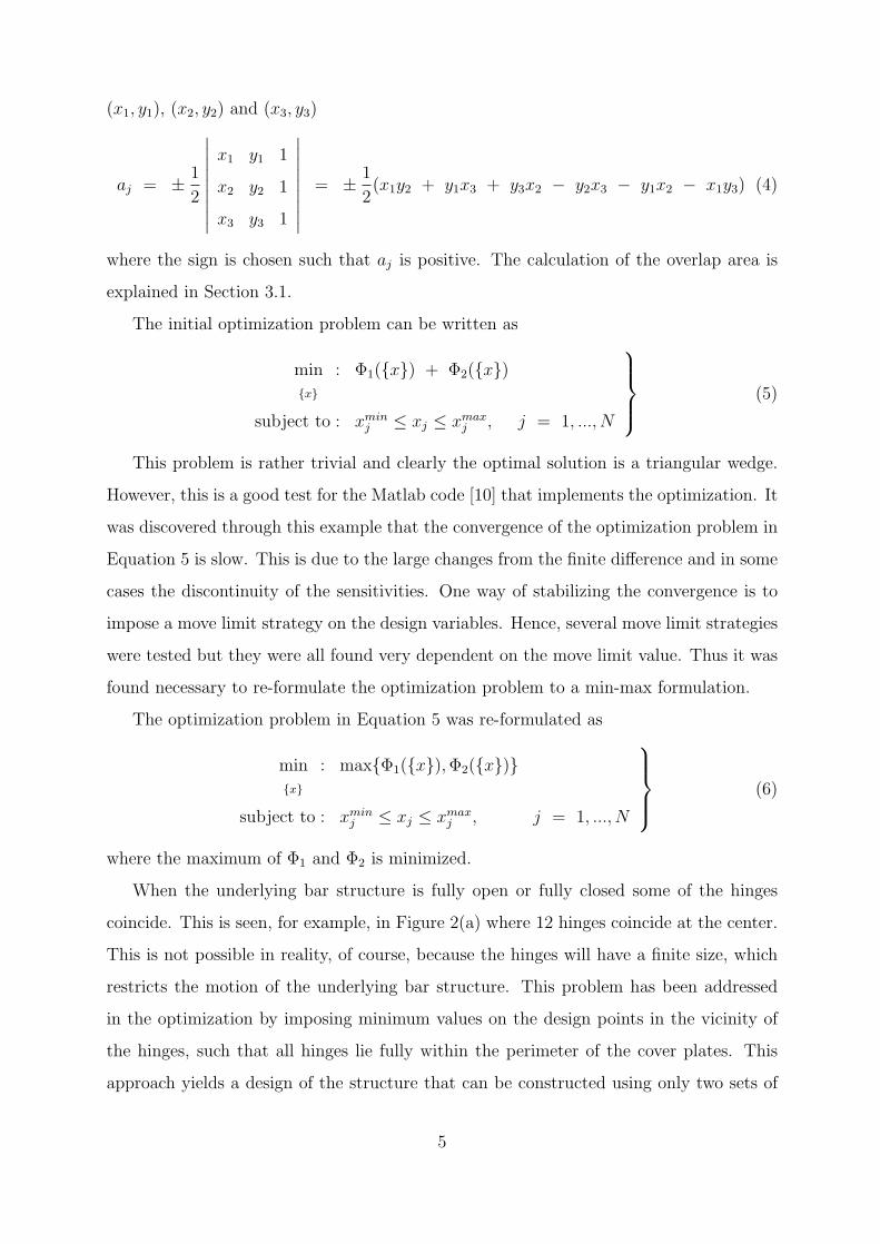
(x1, y1), (x2, y2) and (x3, y3)
aj = ± 12
∣∣∣∣∣∣∣∣∣
x1 y1 1
x2 y2 1
x3 y3 1
∣∣∣∣∣∣∣∣∣= ± 1
2(x1y2 + y1x3 + y3x2 − y2x3 − y1x2 − x1y3) (4)
where the sign is chosen such that aj is positive. The calculation of the overlap area is
explained in Section 3.1.
The initial optimization problem can be written as
min{x}
: Φ1({x}) + Φ2({x})
subject to : xminj ≤ xj ≤ xmax
j , j = 1, ..., N
(5)
This problem is rather trivial and clearly the optimal solution is a triangular wedge.
However, this is a good test for the Matlab code [10] that implements the optimization. It
was discovered through this example that the convergence of the optimization problem in
Equation 5 is slow. This is due to the large changes from the finite difference and in some
cases the discontinuity of the sensitivities. One way of stabilizing the convergence is to
impose a move limit strategy on the design variables. Hence, several move limit strategies
were tested but they were all found very dependent on the move limit value. Thus it was
found necessary to re-formulate the optimization problem to a min-max formulation.
The optimization problem in Equation 5 was re-formulated as
min{x}
: max{Φ1({x}), Φ2({x})}
subject to : xminj ≤ xj ≤ xmax
j , j = 1, ..., N
(6)
where the maximum of Φ1 and Φ2 is minimized.
When the underlying bar structure is fully open or fully closed some of the hinges
coincide. This is seen, for example, in Figure 2(a) where 12 hinges coincide at the center.
This is not possible in reality, of course, because the hinges will have a finite size, which
restricts the motion of the underlying bar structure. This problem has been addressed
in the optimization by imposing minimum values on the design points in the vicinity of
the hinges, such that all hinges lie fully within the perimeter of the cover plates. This
approach yields a design of the structure that can be constructed using only two sets of
5
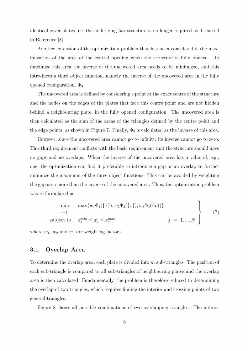
identical cover plates, i.e. the underlying bar structure is no longer required as discussed
in Reference [8].
Another extension of the optimization problem that has been considered is the max-
imization of the area of the central opening when the structure is fully opened. To
maximize this area the inverse of the uncovered area needs to be minimized, and this
introduces a third object function, namely the inverse of the uncovered area in the fully
opened configuration, Φ3.
The uncovered area is defined by considering a point at the exact centre of the structure
and the nodes on the edges of the plates that face this centre point and are not hidden
behind a neighbouring plate, in the fully opened configuration. The uncovered area is
then calculated as the sum of the areas of the triangles defined by the centre point and
the edge points, as shown in Figure 7. Finally, Φ3 is calculated as the inverse of this area.
However, since the uncovered area cannot go to infinity, its inverse cannot go to zero.
This third requirement conflicts with the basic requirement that the structure should have
no gaps and no overlaps. When the inverse of the uncovered area has a value of, e.g.,
one, the optimization can find it preferable to introduce a gap or an overlap to further
minimize the maximum of the three object functions. This can be avoided by weighting
the gap area more than the inverse of the uncovered area. Thus, the optimization problem
was re-formulated as
min{x}
: max{w1Φ1({x}), w2Φ2({x}), w3Φ3({x})}
subject to : xminj ≤ xj ≤ xmax
j , j = 1, ..., N
(7)
where w1, w2 and w3 are weighting factors.
3.1 Overlap Area
To determine the overlap area, each plate is divided into m sub-triangles. The position of
each sub-triangle is compared to all sub-triangles of neighbouring plates and the overlap
area is then calculated. Fundamentally, the problem is therefore reduced to determining
the overlap of two triangles, which requires finding the interior and crossing points of two
general triangles.
Figure 8 shows all possible combinations of two overlapping triangles. The interior
6
points are found by checking if any points in the first triangle satisfy the condition,
graphically explained in Figure 9
Ai =3∑
j=1
aj (8)
where Ai is the area of the second triangle and aj is the area of sub-triangle j.
Hence, Φ2 is found as the sum of all the overlap areas found during the above check.
4 Examples
This section presents five examples of shape optimization of cover plates for retractable
roof structures whose underlying bar structure consists of 12 multi-angulated elements,
each consisting of 3 segments. Details on these structures can be found in References [6]
and [7]. Note that the motion of the covering plates is determined by the motion of this
underlying structure, and hence the coordinates of the design points that define each plate
can be determined by carrying out suitable rigid-body translations and rotations of the
plates.
An initial example is investigated to test the optimization code, written in Matlab.
The optimization problem formulation is found to be slow and unstable, and hence it is
re-formulated. Two examples that make use of the revised code are then shown. Next, an
example is shown where the hinges are defined to have a finite size. Finally, an example
is presented where the uncovered area of the fully opened roof is maximized.
All of these optimization problems were solved with the Method of Moving Asymptotes
(MMA)[9], which requires knowledge of the sensitivities of the object function with respect
to the design variables.
4.1 Minimizing the Gap and Overlap Areas
In the following examples the overlap and gap areas are minimized. In all examples each
side of the cover plates is defined by 10 design points, hence N = 20; no symmetry is
prescribed. All of the plates have the same initial shape and the spacing of the design
points on the central line is set to one unit.
In the first example the initial shape is such that the cover plates overlap, as shown
in Figure 10. Minimizing the overlap and gap areas should result in an optimal design
7
where the overlap in the initial shape disappears.
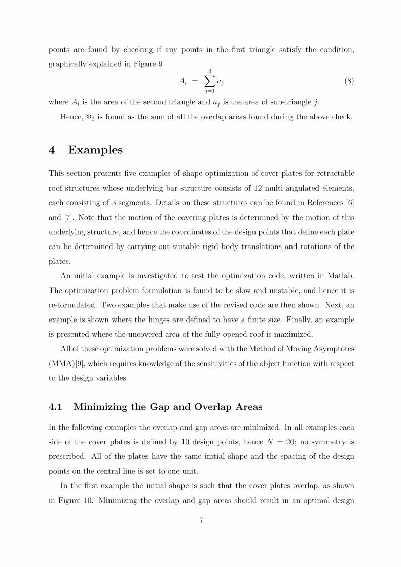
Figure 11 is a plot of the object function as a function of the optimization iterations.
It can be seen that the optimization converges slowly and is also unstable. This is due to
the fact that when the overlap area becomes zero a gap area suddenly appears. Thus the
sensitivities in some cases are discontinuous and the finite difference increments are too
large. Many optimization problems with abrupt changes in the object functions can be
stabilized by imposing move limits on the design variables instead of letting them move
freely between the upper and lower bounds. A move limit constrains the variables by
imposing maximum increment variations.
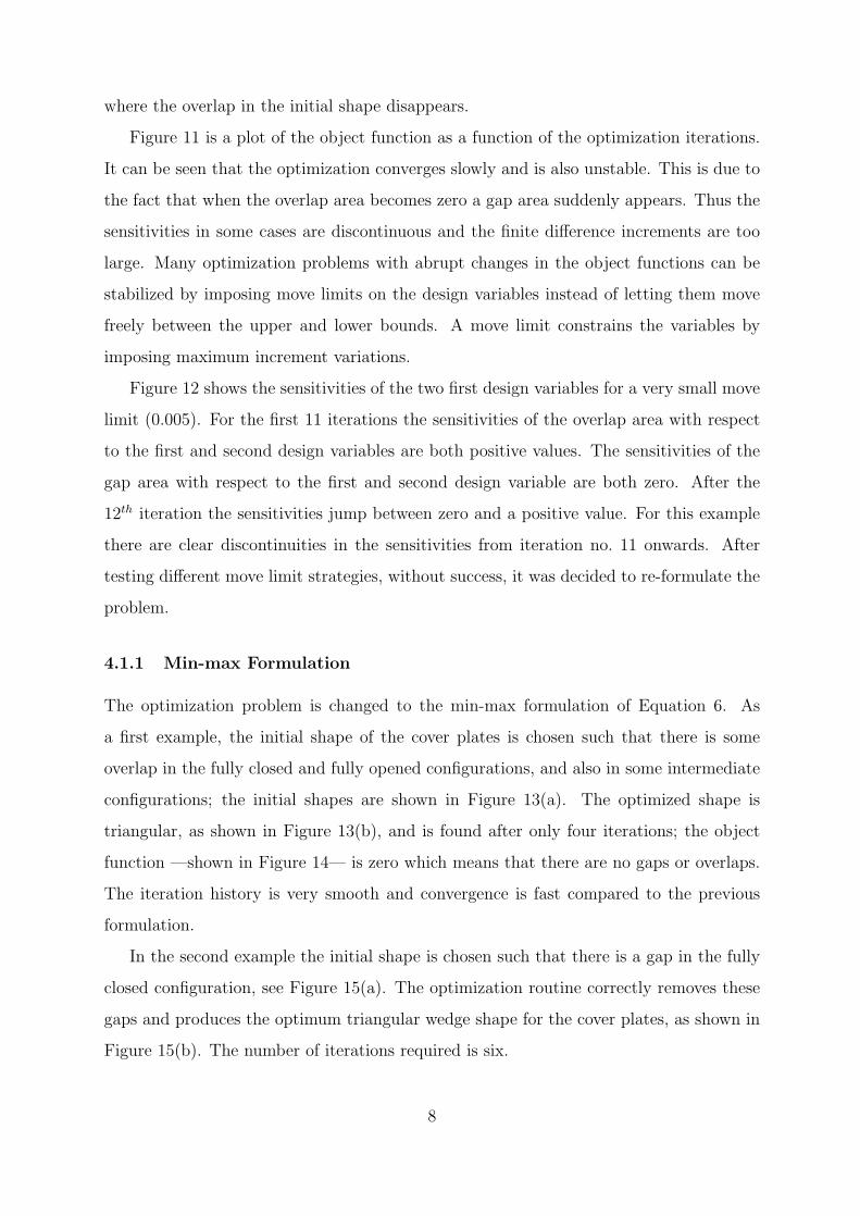
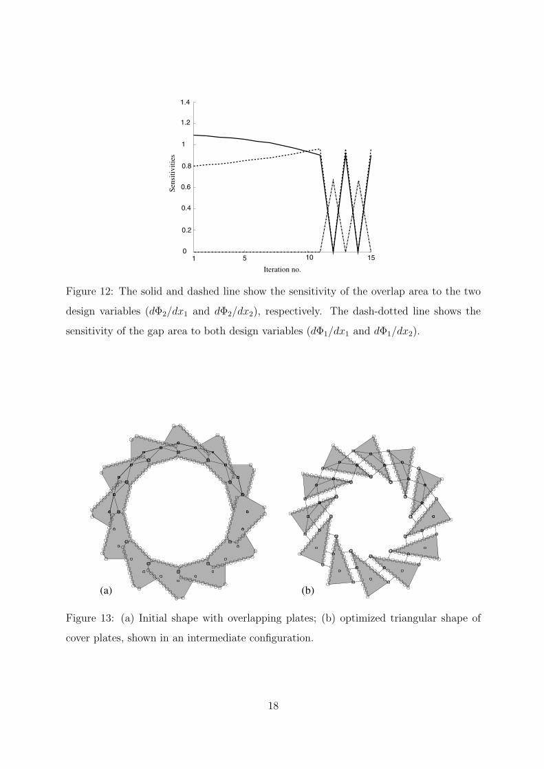
Figure 12 shows the sensitivities of the two first design variables for a very small move
limit (0.005). For the first 11 iterations the sensitivities of the overlap area with respect
to the first and second design variables are both positive values. The sensitivities of the
gap area with respect to the first and second design variable are both zero. After the
12th iteration the sensitivities jump between zero and a positive value. For this example
there are clear discontinuities in the sensitivities from iteration no. 11 onwards. After
testing different move limit strategies, without success, it was decided to re-formulate the
problem.
4.1.1 Min-max Formulation
The optimization problem is changed to the min-max formulation of Equation 6. As
a first example, the initial shape of the cover plates is chosen such that there is some
overlap in the fully closed and fully opened configurations, and also in some intermediate
configurations; the initial shapes are shown in Figure 13(a). The optimized shape is
triangular, as shown in Figure 13(b), and is found after only four iterations; the object
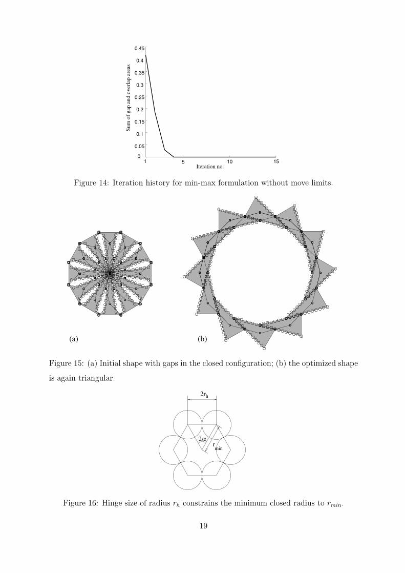
function —shown in Figure 14— is zero which means that there are no gaps or overlaps.
The iteration history is very smooth and convergence is fast compared to the previous
formulation.
In the second example the initial shape is chosen such that there is a gap in the fully
closed configuration, see Figure 15(a). The optimization routine correctly removes these
gaps and produces the optimum triangular wedge shape for the cover plates, as shown in
Figure 15(b). The number of iterations required is six.
8
4.2 Hinges of Finite Size
The first effect of the finite size of the hinges is that the range of motion of the underlying
structure is now restricted [8], therefore the optimization of the shape of the cover plates
needs to be repeated to take into account at least the restricted range of motion. However,
by slightly reformulating the optimization problem we can in fact design plates with finite-
size hinges that lie fully within the perimeter of the plates. Two layers of these plates
can then be used to construct self-supporting structures [8], thus doing away with the
underlying bar structure.
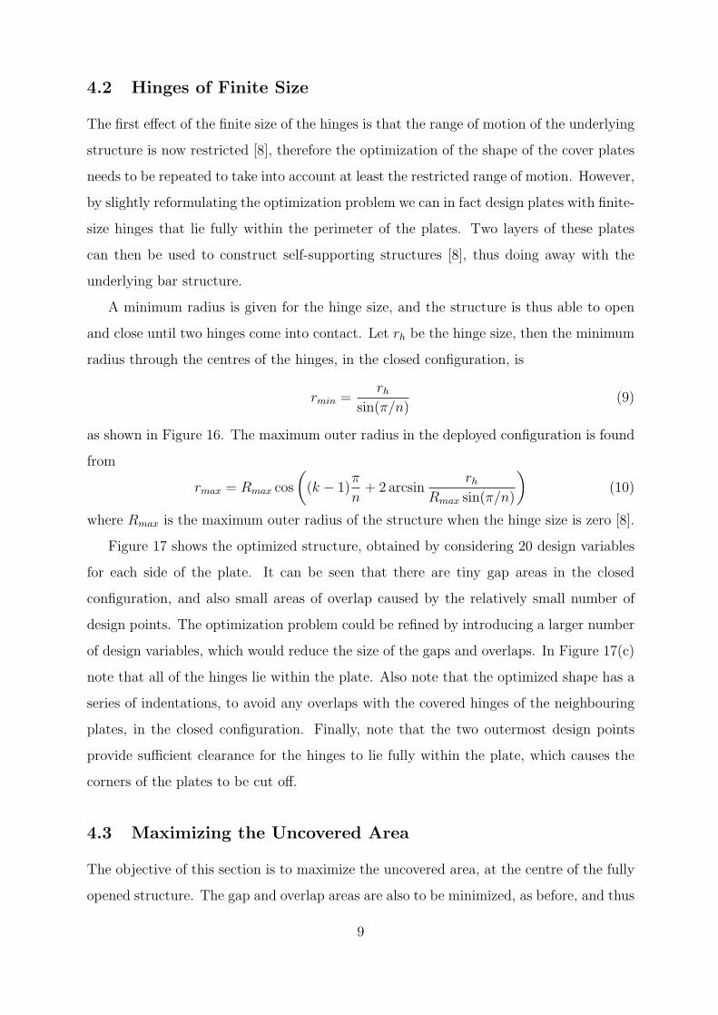
A minimum radius is given for the hinge size, and the structure is thus able to open
and close until two hinges come into contact. Let rh be the hinge size, then the minimum
radius through the centres of the hinges, in the closed configuration, is
rmin =rh
sin(π/n)(9)
as shown in Figure 16. The maximum outer radius in the deployed configuration is found
from
rmax = Rmax cos(
(k − 1)π
n+ 2 arcsin
rh
Rmax sin(π/n)
)(10)
where Rmax is the maximum outer radius of the structure when the hinge size is zero [8].
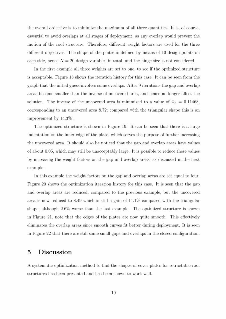
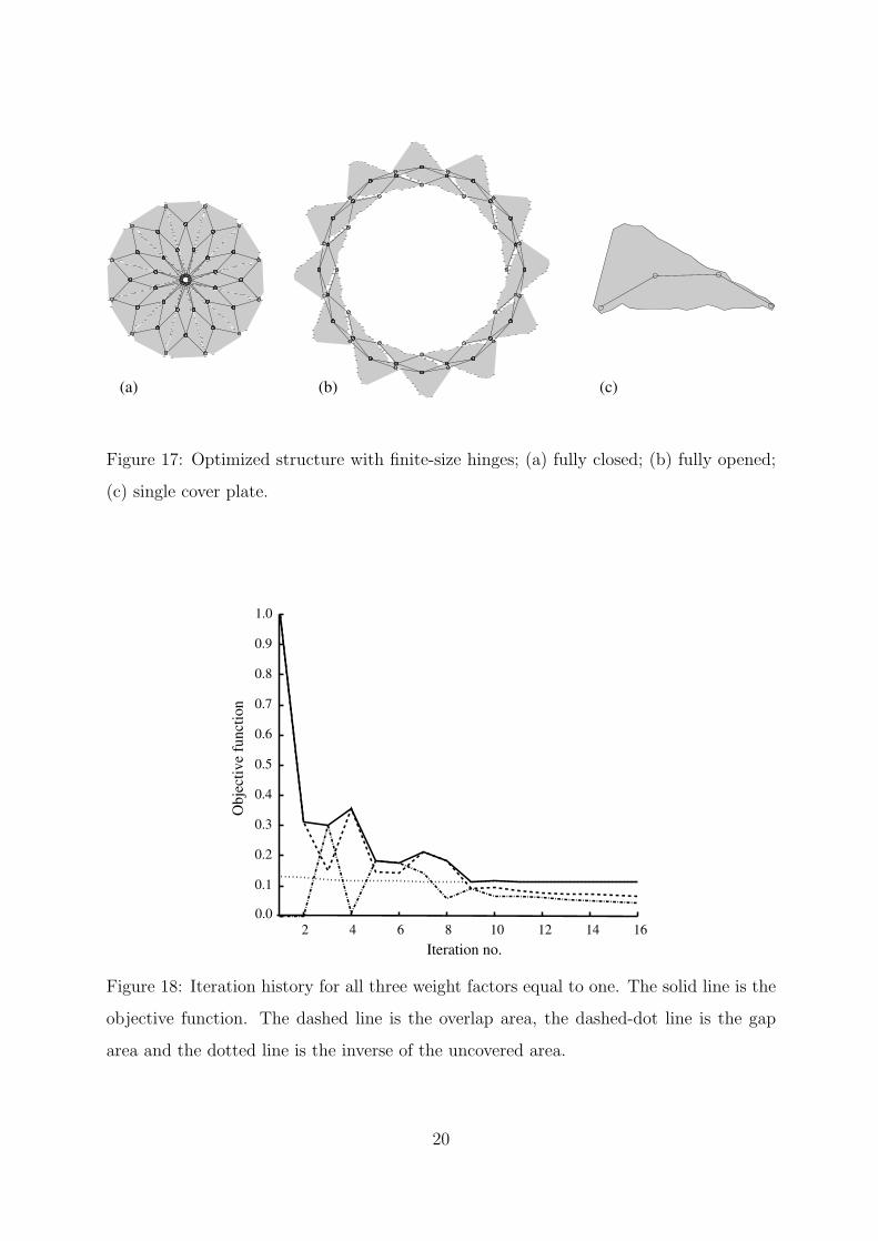
Figure 17 shows the optimized structure, obtained by considering 20 design variables
for each side of the plate. It can be seen that there are tiny gap areas in the closed
configuration, and also small areas of overlap caused by the relatively small number of
design points. The optimization problem could be refined by introducing a larger number
of design variables, which would reduce the size of the gaps and overlaps. In Figure 17(c)
note that all of the hinges lie within the plate. Also note that the optimized shape has a
series of indentations, to avoid any overlaps with the covered hinges of the neighbouring
plates, in the closed configuration. Finally, note that the two outermost design points
provide sufficient clearance for the hinges to lie fully within the plate, which causes the
corners of the plates to be cut off.
4.3 Maximizing the Uncovered Area
The objective of this section is to maximize the uncovered area, at the centre of the fully
opened structure. The gap and overlap areas are also to be minimized, as before, and thus
9
the overall objective is to minimize the maximum of all three quantities. It is, of course,
essential to avoid overlaps at all stages of deployment, as any overlap would prevent the
motion of the roof structure. Therefore, different weight factors are used for the three
different objectives. The shape of the plates is defined by means of 10 design points on
each side, hence N = 20 design variables in total, and the hinge size is not considered.
In the first example all three weights are set to one, to see if the optimized structure
is acceptable. Figure 18 shows the iteration history for this case. It can be seen from the
graph that the initial guess involves some overlaps. After 9 iterations the gap and overlap
areas become smaller than the inverse of uncovered area, and hence no longer affect the
solution. The inverse of the uncovered area is minimized to a value of Φ3 = 0.11468,
corresponding to an uncovered area 8.72; compared with the triangular shape this is an
improvement by 14.3% .
The optimized structure is shown in Figure 19. It can be seen that there is a large
indentation on the inner edge of the plate, which serves the purpose of further increasing
the uncovered area. It should also be noticed that the gap and overlap areas have values
of about 0.05, which may still be unacceptably large. It is possible to reduce these values
by increasing the weight factors on the gap and overlap areas, as discussed in the next
example.
In this example the weight factors on the gap and overlap areas are set equal to four.
Figure 20 shows the optimization iteration history for this case. It is seen that the gap
and overlap areas are reduced, compared to the previous example, but the uncovered
area is now reduced to 8.49 which is still a gain of 11.1% compared with the triangular
shape, although 2.6% worse than the last example. The optimized structure is shown
in Figure 21, note that the edges of the plates are now quite smooth. This effectively
eliminates the overlap areas since smooth curves fit better during deployment. It is seen
in Figure 22 that there are still some small gaps and overlaps in the closed configuration.
5 Discussion
A systematic optimization method to find the shapes of cover plates for retractable roof
structures has been presented and has been shown to work well.
10
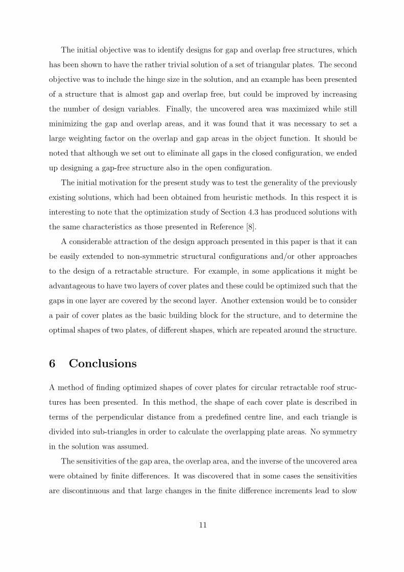
The initial objective was to identify designs for gap and overlap free structures, which
has been shown to have the rather trivial solution of a set of triangular plates. The second
objective was to include the hinge size in the solution, and an example has been presented
of a structure that is almost gap and overlap free, but could be improved by increasing
the number of design variables. Finally, the uncovered area was maximized while still
minimizing the gap and overlap areas, and it was found that it was necessary to set a
large weighting factor on the overlap and gap areas in the object function. It should be
noted that although we set out to eliminate all gaps in the closed configuration, we ended
up designing a gap-free structure also in the open configuration.
The initial motivation for the present study was to test the generality of the previously
existing solutions, which had been obtained from heuristic methods. In this respect it is
interesting to note that the optimization study of Section 4.3 has produced solutions with
the same characteristics as those presented in Reference [8].
A considerable attraction of the design approach presented in this paper is that it can
be easily extended to non-symmetric structural configurations and/or other approaches
to the design of a retractable structure. For example, in some applications it might be
advantageous to have two layers of cover plates and these could be optimized such that the
gaps in one layer are covered by the second layer. Another extension would be to consider
a pair of cover plates as the basic building block for the structure, and to determine the
optimal shapes of two plates, of different shapes, which are repeated around the structure.
6 Conclusions
A method of finding optimized shapes of cover plates for circular retractable roof struc-
tures has been presented. In this method, the shape of each cover plate is described in
terms of the perpendicular distance from a predefined centre line, and each triangle is
divided into sub-triangles in order to calculate the overlapping plate areas. No symmetry
in the solution was assumed.
The sensitivities of the gap area, the overlap area, and the inverse of the uncovered area
were obtained by finite differences. It was discovered that in some cases the sensitivities
are discontinuous and that large changes in the finite difference increments lead to slow
11
convergence. This problem was addressed by adopting a min-max formulation.
A test example, using an object function which minimized the sum of the gap and
overlap areas, showed that triangular plates are a solution to this problem. There are
probably different solutions to this problem, and it would be interesting to explore the
existence of alternatives. However, the description of the shape of the plates may have to
be changed in order to capture other shapes.
Hinges of a finite size were considered, which limit the range of motion of the structure.
Restrictions were put on the cover plates such that all hinges belonging to the same
angulated element have to lie fully within the boundary of a plate. This led to cover plates
of non-triangular shape which show periodic boundary shapes, as found in Reference [8].
The uncovered area when the structure is fully opened was maximized. The results
showed that it was necessary to have larger weighting factors on the gap and overlap
areas compared with the wieight of the uncovered area. The gap and overlap areas would
otherwise be unacceptably high.
Acknowledgments
The authors would like to thank Professors Ole Sigmund, Pauli Pedersen, Martin P.
Bendsøe for many valuable discussions. Part of this work was done while TB was a
visitor at the University of Cambridge, with partial support from the Danish Technical
Research Council through the THOR-program.
References
[1] Escrig F, Valcarcel JP, Sanchez J. Roofing geometry of deployable x-frames. Interna-
tional Journal of Space Structures 1998; 13:1–12.
[2] Valcarcel JP, Escrig F, Martin F. Expandable structures with incorporated roofing
elements. In: Abel JF, Leonard JW, Penalba CU, editors. Spatial, Lattice and Tension
Structures, pp 752–761. New York: ASCE, 1994.
[3] Gantes CJ. Deployable structures: analysis and design. Southampton: WIT Press,
2001.
12
[4] Hoberman C. Reversibly expandable doubly-curved truss structures. US Patent,
4,942,700. July 24, 1990.
[5] Hoberman C. Radial expansion/retraction truss structures. US Patent, 5,024,031.
June 18, 1991.
[6] You Z, Pellegrino S. Foldable bar structures. International Journal of Solids and
Structures 1997, 34(15):1825–1847.
[7] Kassabian PE, You Z, Pellegrino S. Retractable roof structures. Proceedings of
Institution of Civil Engineers, Structures and Buildings 1999, 134(2):45–56.
[8] Jensen F, Pellegrino S. Expandable structures formed by hinged plates. In: Parke
GAR, Disney P, editors. Space Structures 5, pp 263–272. London: Thomas Telford
Limited.
[9] Svanberg K. The method of moving asymptotes - a new method for structural opti-
mization. International Journal for Numerical Methods in Engineering 1987, 24:359–
373.
[10] MathWorks. Matlab user’s guide, version 6. 2001.
13
(b)(a)
αF
D
A
θEO
C
B
O
DEα
A
θ
B
C
Figure 1: (a) Pantograph element; (b) angulated element.
(b)(a) (c)
Figure 2: Circular retractable bar structure formed by one-and-half interconnected rings of
identical angulated elements, at three stages of deployment. Sets of consecutive angulated
elements, of which one is highlighted, are joined to form multi-angulated elements.
Figure 3: Top view of stadium covered by rigid plates.
14
����������
����������
����������
����������
Overlap area
r(a) (b)
Gap area
������������������������������������������������������������������������
������������������������������������������������������������������������
��������������������������������������������������������������������
��������������������������������������������������������������������
Figure 4: (a) Gap and (b) overlap between two neighbouring plates.
min
max
design point
xj
β
yj
xmaxj
Figure 5: Cover plate with design points and their minimum and maximum values.
a j
subtriangle
design point
Figure 6: Definition of sub-triangles.
15
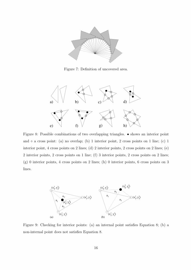
Figure 7: Definition of uncovered area.
a) b) c) d)
e) f) g) h)
Figure 8: Possible combinations of two overlapping triangles. • shows an interior point
and ◦ a cross point: (a) no overlap; (b) 1 interior point, 2 cross points on 1 line; (c) 1
interior point, 4 cross points on 2 lines; (d) 2 interior points, 2 cross points on 2 lines; (e)
2 interior points, 2 cross points on 1 line; (f) 3 interior points, 2 cross points on 2 lines;
(g) 0 interior points, 4 cross points on 2 lines; (h) 0 interior points, 6 cross points on 3
lines.
k2 2
k(x , y )
(x , y )11 1
1
(x , y )21 1
2
a
a
a
2
1
(x , y )31 1
3
3
(x , y )11 1
1
(x , y )21 1
2k2 2
k(x , y )
a1
a2
a3
(x , y )31 1
3
(a) (b)
Figure 9: Checking for interior points: (a) an internal point satisfies Equation 8; (b) a
non-internal point does not satisfies Equation 8.
16
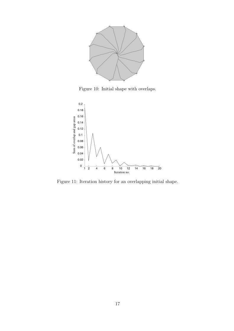
Figure 10: Initial shape with overlaps.
1 2 4 6 8 10 12 14 16 18 200
0.02
0.04
0.06
0.08
0.1
0.12
0.14
0.16
0.18
0.2
Sum
of
over
lap
and
gap
area
s
Iteration no.
Figure 11: Iteration history for an overlapping initial shape.
17
1 5 10 150
0.2
0.4
0.6
0.8
1
1.2
1.4
Sens
itivi
ties
Iteration no.
Figure 12: The solid and dashed line show the sensitivity of the overlap area to the two
design variables (dΦ2/dx1 and dΦ2/dx2), respectively. The dash-dotted line shows the
sensitivity of the gap area to both design variables (dΦ1/dx1 and dΦ1/dx2).
(a) (b)
Figure 13: (a) Initial shape with overlapping plates; (b) optimized triangular shape of
cover plates, shown in an intermediate configuration.
18
1 5 10 150
0.05
0.1
0.15
0.2
0.25
0.3
0.35
0.4
0.45
Sum
of
gap
and
over
lap
area
s
Iteration no.
Figure 14: Iteration history for min-max formulation without move limits.
(b)(a)
Figure 15: (a) Initial shape with gaps in the closed configuration; (b) the optimized shape
is again triangular.
2rh
α2rmin
Figure 16: Hinge size of radius rh constrains the minimum closed radius to rmin.
19
(a) (b) (c)
Figure 17: Optimized structure with finite-size hinges; (a) fully closed; (b) fully opened;
(c) single cover plate.
0.1
0.2
0.3
0.4
0.5
0.6
0.7
0.9
0.8
0.0
1.0
2 4 6 8 10 12 14 16
Obj
ectiv
e fu
nctio
n
Iteration no.
Figure 18: Iteration history for all three weight factors equal to one. The solid line is the
objective function. The dashed line is the overlap area, the dashed-dot line is the gap
area and the dotted line is the inverse of the uncovered area.
20
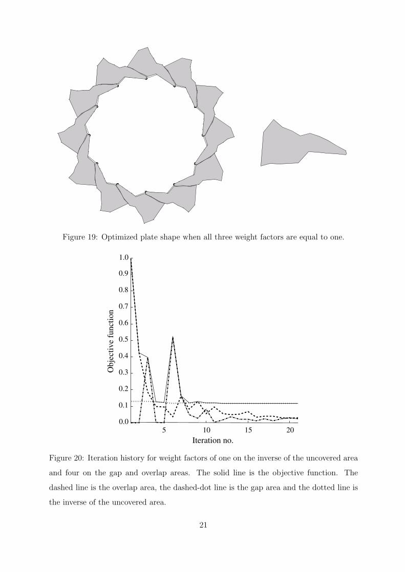
Figure 19: Optimized plate shape when all three weight factors are equal to one.
5 10 15
1.0
0.9
0.8
0.7
0.6
0.5
0.4
0.3
0.2
0.1
0.020
Obj
ectiv
e fu
nctio
n
Iteration no.
Figure 20: Iteration history for weight factors of one on the inverse of the uncovered area
and four on the gap and overlap areas. The solid line is the objective function. The
dashed line is the overlap area, the dashed-dot line is the gap area and the dotted line is
the inverse of the uncovered area.
21
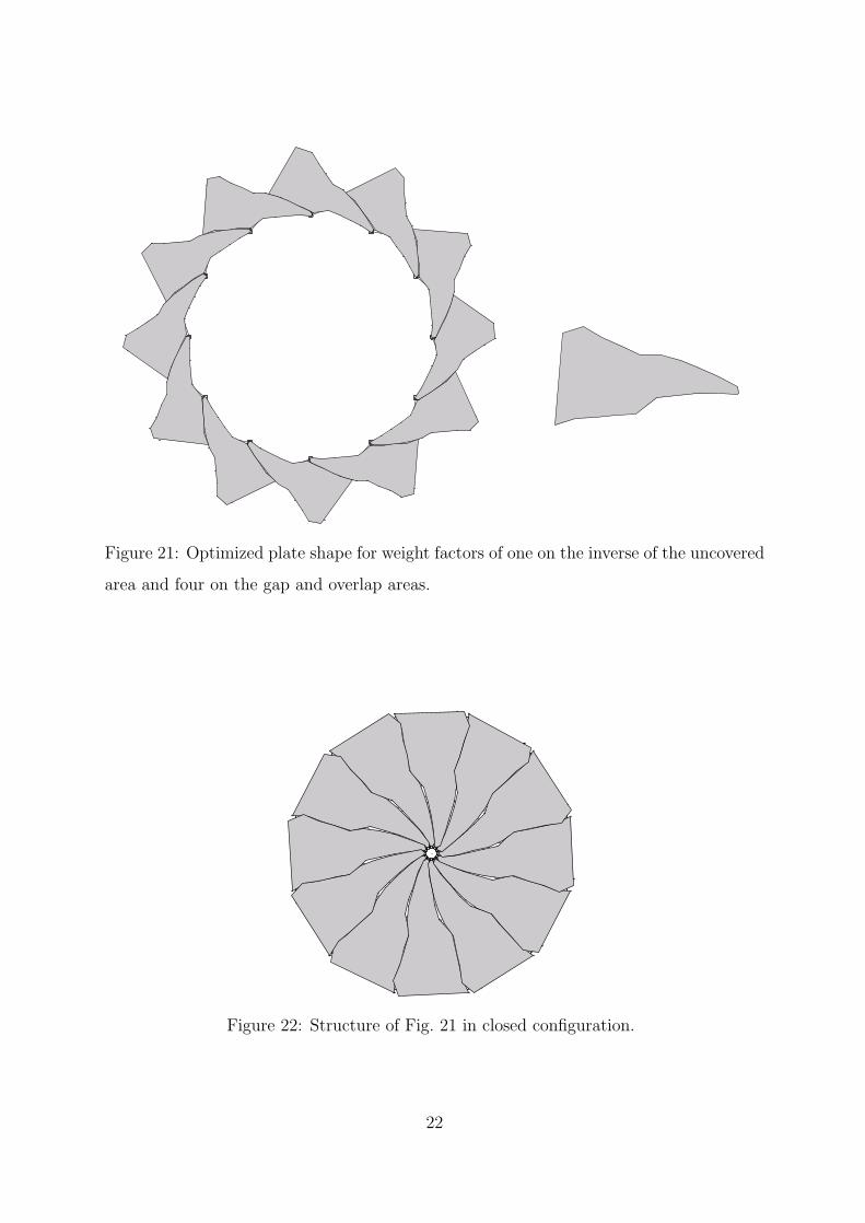
Figure 21: Optimized plate shape for weight factors of one on the inverse of the uncovered
area and four on the gap and overlap areas.
Figure 22: Structure of Fig. 21 in closed configuration.
22