Embed Size (px)
Citation preview

American Institute of Aeronautics and Astronautics
1
Shape Memory Rigidizable Inflatable (RI) Structures for
Large Space Systems Applications
John K. H. Lin*, Carl F. Knoll
† and Cliff E. Willey
‡
ILC Dover LP, Frederica, Delaware, 19946
DARPA and NASA have recognized ultra-lightweight shape memory Rigidizable
Inflatable (RI) structures as an enabling technology for future space and interplanetary
missions requiring large space systems. There are many benefits of using advanced Shape
Memory Polymer (SMP) materials in large space structures such as high compaction ratio,
increased design flexibility, and reduced complexity. These benefits are similar to the
benefits of pure inflatable applications, but without the disadvantages of high coefficient of
thermal expansion (CTE) and the need of constant make up gas for maintaining inflation.
Furthermore, it has higher structural stiffness and higher accuracy as compared to pure
inflatable applications. To date, ILC Dover has developed and continued to mature and test
several types of SMP material systems. These material systems include single glass transition
temperature (Tg) systems with customizable Tg ranging from 0°°°°C to 120°°°°C and dual Tg
systems that have an initial low Tg and can be triggered on command by heat, radiation (UV,
etc.) or chemical exposure to a higher Tg. It is important for the space community to
understand the major differences the SMP technologies bring to large space systems. This
paper will discuss current SMP materials and then examine the implication of SMP
technology as it relates to large space systems and how it can enable future missions.
I. IntroductionARPA and NASA have recognized ultra-lightweight shape memory Rigidizable Inflatable (RI) structures as an
enabling technology for future space and interplanetary missions requiring large space systems. The enabling
feature is the ability of the material to be compacted very tightly; extremely large structures can be stowed into
existing launch vehicles or smaller launchers. There are additional benefits of using advanced Shape Memory
Polymer (SMP) materials in large space structures:
• High compaction ratios – Volumetric compaction in % of deployed volume
• Increased design flexibility – Inflatables can be stowed in numerous ways
• Reduced complexity – Large deployed trusses without hinges or mechanisms
• Reduced weight – RI structures can be stowed so as not to carry large launch loads, therefore the
structure can be ultra-lightweight because they only need to handle the relatively small on-orbit loads.
• Low Thermal distortion – RI structures can have balanced composite materials that approach near
zero thermal expansion.
• High on-orbit stiffness – Compared to a pure inflatable, like Echo or IAE, the composite structures can
attain very good relative stiffness.
• Ground Testability – RI structures, at small to medium scale, can be deployed in ground testing. It is
fully reversible.
To date, ILC Dover has developed and continued to mature and test several types of SMP material systems.
These material systems include single glass transition temperature (Tg) systems with customizable Tg ranging from
0°C to 120°C, and dual Tg systems that have an initial low Tg and can be triggered on command by heat, radiation
(UV, etc.) or chemical exposure to a higher Tg. It is important for the space community to understand the major
differences the rigidizable technologies bring to large space systems. Rigidizables cannot be compared to the
membrane applications because the system implications are very different. This paper will discuss current
* Lead Design Engineer and Group Supervisor, Engineered Products Group, One Moonwalker Road/MS22, Member
AIAA.† System Engineering Manager, Engineering Department, One Moonwalker Road/MS32, Member AIAA.
‡ Space Inflatables Program Manager, Space Products, One Moonwalker Road/MS32, Member AIAA.
D
47th AIAA/ASME/ASCE/AHS/ASC Structures, Structural Dynamics, and Materials Confere1 - 4 May 2006, Newport, Rhode Island
AIAA 2006-1896
Copyright © 2006 by ILC Dover LP. Published by the American Institute of Aeronautics and Astronautics, Inc., with permission.

American Institute of Aeronautics and Astronautics
2
rigidizable materials and examine the classes of structures with the implication of SMP technology as it relates to
large space systems and how it can enable future missions.
In the past several decades, the gossamer spacecraft community has classified large space structure material
systems into two different groups, namely mechanical and inflatable systems. However, with recent advancement in
material technology there is another group that is distinct from these two which requires a new classification.
Rigidizable Inflatables (RI) need to be identified as a unique material system and structure. In addition, the
community has generated overall basic classifications for large space structures:
• Self-Deployed – Mechanical, RI and Inflatables are basic subclasses with trusses and large surface
reflectors as types of applications.
• On-Orbit Assembled – Astronaut and robotic construction of structural elements. This may be
enabling for the types of structures required for Lunar outpost assembly
• On-Orbit Manufactured – This class enables the extremely large structures envisioned for apertures or
in-space trusses of +1000M.
The application of RI materials for these classes will be also discussed in this paper.
II. RI Structure Material CharacteristicsWith the unique benefits and advantages of this class of material, it is imperative for the aerospace and military
communities to understand the implication of inserting SMP technology into various space applications. In dealing
with RI materials, many types of rigidization mechanisms exist. In general, RI materials can be defined as materials
that are initially flexible to facilitate packing and deployment, deployed via internal inflation pressure, and become
rigid once exposed to an external influence such as heat, radiation or vacuum.1, 2
In this paper the discussion will
focus only on thermally activated SMP composite materials and structures.
In the past several years, ILC Dover has developed, tested and matured numerous SMP composite systems for
large space structural applications. These composite material systems were primarily based on single glass transition
temperature systems with Tg ranging from 50°C to 95°C. Structures fabricated from SMP composite materials are
made utilizing similar methods as that of traditional thermoset composite structures. The final deployed or
operational shape of the SMP composite structure is established (i.e. fixed or set) during its initial cure cycle. Once
the SMP material is completely cured, it can be heated to the folding temperature (typically 20oC above the Tg)
where it becomes flexible and can be tightly packed (folded and/or rolled). The flexibility of the SMP composite
material at the folding temperature depends strongly on both the resin and fiber properties. Once the structure is
packed, it is constrained in that position until cooled to approximately 15oC or lower below Tg at which point the
SMP composite structure will remain locked or frozen in the packed position unrestrained until it is again heated
above the Tg. When the SMP structure is heated (and unconstrained by launch tie), internal strain energy will
naturally return to its initial cured shape. The speed and the accuracy of the shape return are a function of the shape
memory recovery force of the composite. In most large structure applications when the SMP materials are tightly
packed (hard creased) the shape memory recovery force of the composite will return the structure to 90 ~ 98% of the
initial cured shape unassisted. For most applications that require better accuracy, inflation while above the Tg is
required to supplement the recovery force to return the structure to its original cured shape. Once the structural
system is deployed and cooled to 15oC below Tg, it will again be structurally rigid and will no longer require the
support of the inflation pressure.
III. RI structure deployment vs. mechanized deployable structureThe need for deployable structures in space application required when the physical dimensions of the
spacecraft’s operational configuration are larger than the launch vehicle fairing dimensions thus requiring
reconfiguration of structural systems for stowage and on-orbit deployment. Deployable instrument masts, antennas,
solar arrays, radiators and sunshields are some examples of deployable space structures currently in operation.
The current means for changing structural configuration on-orbit are through the use of hinges, strain energy or
stored energy devices, motor driven and on-orbit assembly. A typical mechanically deployed space structure would
use single and multiple degree of freedom hinges to deploy (reorient and reconfigure) rigid structures connected
together by the hinges. The deployment forces required to reconfigure the structure could be motor driven or from
store energy devices (i.e. springs). In most applications, the hinges would lock at the end of the deployment and be
capable of transferring structural loads. In addition to hinges, strain energy devices are also used, often in
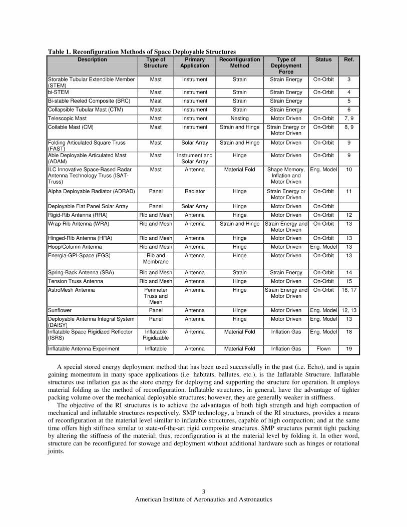
combination with hinges. Table 1 below is a comparative study on space deployable structures comparing different
reconfiguration methods.
American Institute of Aeronautics and Astronautics
3
Table 1. Reconfiguration Methods of Space Deployable StructuresDescription Type of
StructurePrimary
ApplicationReconfiguration
MethodType of
DeploymentForce
Status Ref.
Storable Tubular Extendible Member(STEM)
Mast Instrument Strain Strain Energy On-Orbit 3
bi-STEM Mast Instrument Strain Strain Energy On-Orbit 4
Bi-stable Reeled Composite (BRC) Mast Instrument Strain Strain Energy 5
Collapsible Tubular Mast (CTM) Mast Instrument Strain Strain Energy 6
Telescopic Mast Mast Instrument Nesting Motor Driven On-Orbit 7, 9
Coilable Mast (CM) Mast Instrument Strain and Hinge Strain Energy orMotor Driven
On-Orbit 8, 9
Folding Articulated Square Truss(FAST)
Mast Solar Array Strain and Hinge Motor Driven On-Orbit 9
Able Deployable Articulated Mast(ADAM)
Mast Instrument andSolar Array
Hinge Motor Driven On-Orbit 9
ILC Innovative Space-Based RadarAntenna Technology Truss (ISAT-Truss)
Mast Antenna Material Fold Shape Memory,Inflation andMotor Driven
Eng. Model 10
Alpha Deployable Radiator (ADRAD) Panel Radiator Hinge Strain Energy orMotor Driven
On-Orbit 11
Deployable Flat Panel Solar Array Panel Solar Array Hinge Motor Driven On-Orbit
Rigid-Rib Antenna (RRA) Rib and Mesh Antenna Hinge Motor Driven On-Orbit 12
Wrap-Rib Antenna (WRA) Rib and Mesh Antenna Strain and Hinge Strain Energy andMotor Driven
On-Orbit 13
Hinged-Rib Antenna (HRA) Rib and Mesh Antenna Hinge Motor Driven On-Orbit 13
Hoop/Column Antenna Rib and Mesh Antenna Hinge Motor Driven Eng. Model 13
Energia-GPI-Space (EGS) Rib andMembrane
Antenna Hinge Motor Driven On-Orbit 13
Spring-Back Antenna (SBA) Rib and Mesh Antenna Strain Strain Energy On-Orbit 14
Tension Truss Antenna Rib and Mesh Antenna Hinge Motor Driven On-Orbit 15
AstroMesh Antenna PerimeterTruss and
Mesh
Antenna Hinge Strain Energy andMotor Driven
On-Orbit 16, 17
Sunflower Panel Antenna Hinge Motor Driven Eng. Model 12, 13
Deployable Antenna Integral System(DAISY)
Panel Antenna Hinge Motor Driven Eng. Model 13
Inflatable Space Rigidized Reflector(ISRS)
InflatableRigidizable
Antenna Material Fold Inflation Gas Eng. Model 18
Inflatable Antenna Experiment Inflatable Antenna Material Fold Inflation Gas Flown 19
A special stored energy deployment method that has been used successfully in the past (i.e. Echo), and is again
gaining momentum in many space applications (i.e. habitats, ballutes, etc.), is the Inflatable Structure. Inflatable
structures use inflation gas as the store energy for deploying and supporting the structure for operation. It employs
material folding as the method of reconfiguration. Inflatable structures, in general, have the advantage of tighter
packing volume over the mechanical deployable structures; however, they are generally weaker in stiffness.
The objective of the RI structures is to achieve the advantages of both high strength and high compaction of
mechanical and inflatable structures respectively. SMP technology, a branch of the RI structures, provides a means
of reconfiguration at the material level similar to inflatable structures, capable of high compaction; and at the same
time offers high stiffness similar to state-of-the-art rigid composite structures. SMP structures permit tight packing
by altering the stiffness of the material; thus, reconfiguration is at the material level by folding it. In other word,
structure can be reconfigured for stowage and deployment without additional hardware such as hinges or rotational
joints.
American Institute of Aeronautics and Astronautics
4
IV. System Level Implications of SMP Technology InsertionThis section will address two basic on-orbit applications of interest from a systems perspective; dish type
antennas, and booms or columns that form large structural systems. As will be discussed in a later section, these are
the primary types of applications evaluated for potential missions using the SMP technology. How the SMP class of
rigidizable structure can improve existing applications and enable new missions will be discussed. SMP structures
will be compared to standard mechanical configurations at a system level. Typical design drivers to a structure
configuration, being the launch loads, launch volume, launch mass and on-orbit dynamic loads, will be addressed.
The SMP approach will be compared with current structure paradigms such as typical hinged configurations and
strain energy deployments.
A. Continuing the Evolution of Increasing Structural EfficiencyComposite materials that are flight qualified today addressed the launch mass and CTE issues of the metals they
replace. This replacement, much like the transition from wood to metals starting in the 1920’s, is another step in the
development of more efficient aerospace structures. During the early composite development period, when
composites started replacing metals, there were new manufacturing and test methods qualified that provided the
confidence in what was then a new structure approach for space applications. The increasing usage of composites in
the optimization driven aerospace industry is evidence of an improvement over the structure materials that are being
replaced. These improvements are seen as structures that otherwise would be a greater percentage of the mission
mass or have increased capabilities with the same mass. When Coefficient of Thermal Expansion (CTE) issues are a
concern, composite materials allow configurations with less elaborate mechanical isolation or no de-coupling
required between components. Further development of SMP composites can provide an improvement to the
composite structure approach by reducing the need for typical deployment mechanisms. Instead of just replacement
of metal to composite load carrying materials for a decrease in mass, the SMP technology allows a fundamental
change in the stowage and deployment methods while keeping the original benefits of composites.
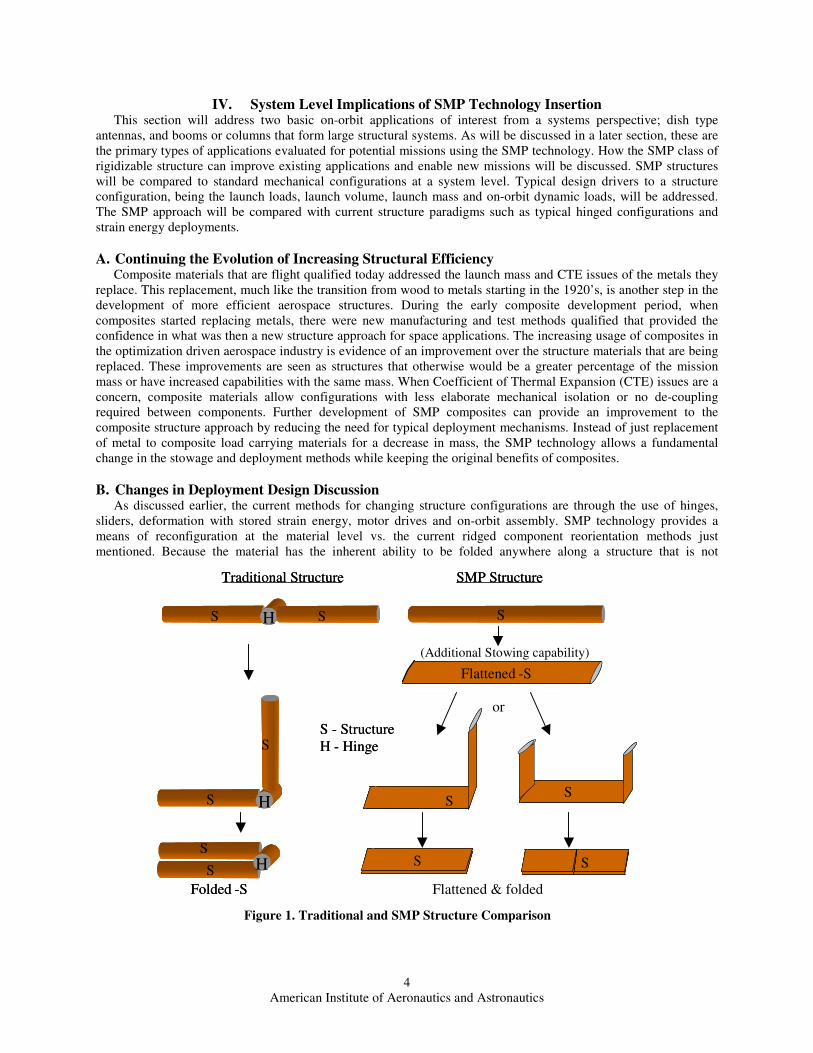
B. Changes in Deployment Design DiscussionAs discussed earlier, the current methods for changing structure configurations are through the use of hinges,
sliders, deformation with stored strain energy, motor drives and on-orbit assembly. SMP technology provides a
means of reconfiguration at the material level vs. the current ridged component reorientation methods just
mentioned. Because the material has the inherent ability to be folded anywhere along a structure that is not
H SS
H
S
S
HS
S
S
S - Structure
H - Hinge
Flattened -S
Folded -S
SMP StructureTraditional Structure
H SS
H
S
S
HS
S
S
S - Structure
H - Hinge
Flattened -S
Flattened & foldedFolded -S
SMP StructureTraditional Structure
(Additional Stowing capability)
S
S S
S
or
Figure 1. Traditional and SMP Structure Comparison

American Institute of Aeronautics and Astronautics
5
constrained by an item being supported, different packing configurations are possible without redesigning structure
members and the relocating of discrete mechanisms. This is a mission enabling capability because of the
combination of eliminating the traditional mechanisms between rigid members and adding an additional level of
stowing of the structural members (i.e., volume reduction, a load carrying beam that is longitudinally stowed into a
flat and reshaped on orbit). The benefits and challenges at the system level of utilizing the SMP technology will now
be discussed. Figure 1 is a pictorial comparison of the traditional mechanism approach and the SMP approach just
discussed.
Payload or mission designs and the available launch vehicle volumes are what drive the addition of deployment
and reconfiguration mechanisms into a design. The satellite configuration required on-orbit is not always compatible
with the available volume and configuration of the fairing. Although adding an element of risk, the deployment
mechanisms are enablers for these missions. This paradigm has become an acceptable and common practice. A
structural configuration using the SMP material allows a kinematically similar stowing of the structure compared to
a hinge, but without the discontinuity or discrete components. The addition of hinges and other mechanisms requires
an increase in the parts count of a system as well as a discontinuity that must be managed. In general, if one were to
consider a structural member sized for an on-orbit loading condition, the member is likely to have a constant linear
density. If this same structural member requires folding to fit within a fairing, the addition of the mechanism will
typically cause the linear density to be greater at that location. This is in addition to the complexity of the multi-part
hinge component. An exception may be a carpenter tape type hinge mechanism, but the trade for this type of
mechanism is lower deployed structural rigidity and stored energy requiring a restraint at that location. The ability of
the material to perform as a hinge, in addition to the structure, can be considered as a multifunctional or functionally
integrated approach. Evolving structures from the current state of the art to this method will provide increases in
structural, mass and reconfiguration efficiency for missions that are currently feasible and will allow enabling new
missions where current mechanisms cannot effectively provide the mechanical transformations. The fabrication of a
more continuous structure with a lower parts count is an also advantage in the structure manufacturing cost.
C. Application in Antenna StructureIn the case of antenna dish surfaces, a single piece rigid surface is constrained by size to what will fit within the
fairing. Larger antenna surfaces may be segmented and repositioned once on-orbit. These rely on the ability of the
deployment mechanisms to accurately reposition the discrete segments to obtain a surface with an acceptable overall
shape. These segments are also required to be stiff enough to survive the launch environment. This is typically done
by the support structure behind the reflective surface. Using the SMP material, the desired surface profile is obtained
similarly to the way a traditional composite antenna is formed. A mold surface is used to provide the cured surface
profile. Whereas the traditional antenna surface will have a significant structural backing to the reflective surface,
usually driven by launch loads, the SMP surface can be sized for the typically lower on-orbit loading conditions.
This is possible because the SMP dish can be heated to above the material folding Tg and reconfigured by literally
folding the surface. To enable the deployment and final shaping on orbit the surface will have thin film heaters
installed to reheat the surface to above the Tg just prior to deployment. Thin films are used as bladders for the
inflation gas to deploy and reshape the surface. These heaters and films are on the order of the thickness of the thin
composite surface and fold with the dish. The capability to perform tight folds allows the stowed configuration to be
more efficient by not requiring a separate snubbing function between each of the folded layers as is often done
between stowed panel-like components such as solar arrays or segmented antennas.
Stowed antennas will also typically require restraints to constrain the motions induced by launch loads. In the
case of the hinged configurations this function is sometimes integrated with the hinge mechanism(s). Configurations
that have been evaluated for the SMP antennas are similar to the traditional tie-downs, but for a given antenna
surface area are likely to be smaller because of the lower overall restrained mass. Another non-traditional restraint
configuration that has been evaluated is a soft cover over the folded and rigidized stowed configuration. Releasing
the tensioned fabric allows the antenna to be deployed once above its Tg.
D. Mass Reduction through Efficient Stowage DesignThe ability to more efficiently stow structures for launch allows a reduction in structural mass allocated for the
purposes of surviving that short and transient phase of a mission. The stowed configuration of SMP components is
in a rigid condition that also causes the material to be ‘locked out’. This rigidization of the material at the hinging or
folding point does not require an additional restraint. There will still be a requirement to restrain the bulk payload
mass but the SMP provides more of a ‘lump’ rigid mass than multiple discrete parts connected through movable
interfaces. The ability to make on-orbit loads the structure design driver vs. the typically higher launch loads can
lower the driving structural strength requirement. A side effect of the lower strength is the deployed structure that

American Institute of Aeronautics and Astronautics
6
may not be as conducive to ground testing. Developing new test methods or shifting the emphasis from ground test
to other validation or accommodation methods (i.e., on-orbit adjustment) must be considered.
E. Changes in Ground TestingWith the possibility of not having the launch loads drive structure sizing, designing exclusively for orbital loads
may create a ground test challenge where 1-g loading may be beyond the structure capability. This is the case
already in many space sub-systems, such as solar arrays, where off-loading using ground test fixtures support a
deploying and/or deployed system. By further reducing the mass of a structure, because of better launch load
carrying configurations, the test fixturing potentially becomes a greater test influence if not properly designed. This
is especially the case where precision structures are measured on the ground. An extremely light and low strength
structure will more easily be ‘influenced ‘ by the fixturing. An example of this type problem would be an unlevel
deployment support fixture that ‘helps’ the deployment because of the influence of gravity. This scenario could
potentially mask a hang-up condition with the fixture overcoming the hang point. In the case of SMP structures there
is less of chance of component failures. With an SMP material it is important that the material condition be correct
during the deployment. This means appropriate thermal control and monitoring during deployment. Introducing an
inflation gas while a stowed SMP component is still rigid can very likely damage the matrix by loading a rigid fold
line. Once the material is properly heated and unrestrained there is still the concern of hanging up on other local
components as with any deployable, but the potential for ‘internal’ component problems is reduced.
F. Inflation System DiscussionAs discussed above, the SMP material does have a shape restoring capability, albeit not usually great enough to
completely redeploy to the final configuration. As discussed in the material section the desired final configuration is
usually the ‘as manufactured’ configuration. In the majority of the applications studied and prototyped, an inflation
gas was used to augment the inherent deployment force. In the case of the inflation deployment, the mass of the gas
subsystem is of the same ‘category’ as the springs and drivers of the mechanical mechanisms. In most of the
inflation system configurations multiple deployments (i.e., unfolding) as well as the reconfiguration of the structural
member reshaping was done with the same gas system, in some cases all at the same time.
G. Truss Structure ApplicationGiven that a mission stowed configuration will fit in a fairing; there is a trade that should be performed that
considers the structure size and shape complexity to see if the SMP configuration is more efficient. In the very large
applications that have been conceptualized and SMP prototypes built, it was found that large structures benefit from
the new technology and in extremely large structures it is the enabler. The system stowed structure does need to be
large enough to exceed the breakeven point of a mechanism vs. SMP system for SMP to be efficient. As an extreme
example it is fairly obvious that an inflation system would have more mass than a single hinge. It is when there is
the ‘collapsing’ of the structural members to increase the storage efficiency and the elimination of multiple
mechanical joints that the SMP approach can improve performance. In one example of a very large and repeatable
structure (a repeating truss) the deployment design for the SMP structure utilized a single deployment mechanism (a
linear drive mechanism) to deploy the multiple repeating sections. The stowed truss shape was obtained by passing
each section through this single deployment mechanism that deployed each bay one at a time. This reduces the parts
count by using the deployment mechanism multiple times compared to each bay having its own set of mechanisms
that are used only once for that bay. Although as a mechanism it was more complex than a simple hinge, the
mechanism mass was located in a more centralized position and not distributed along the length of the structure.
This aided in two ways, first there were no deployment mechanism that had to be stowed within the packed structure
(allowing tighter structure packing) and second the mass at the root of the truss was better from a system mass
properties and on-orbit control perspective.
V. Recent SMP RI Development Programs and Results
A. SMP Composite Antenna Truss Structure DevelopmentA truss structure assembled from cylindrical booms, similar to the system described in Section IV-G, has
recently been fabricated and tested at ILC Dover. The truss structure was assembled from 45.7-mm diameter by 1.5-
m long booms. The booms were fabricated using 2 plies of IM7 and shape memory polymer. To demonstrate the
packing and deployment of this technology, heaters were integrated onto the outside of the booms and covered by

American Institute of Aeronautics and Astronautics
7
multi-layer insulation. Figure 2 shows the truss in both the deployed and packed positions. This SMP truss can be
designed to a compaction ratio (deployed-to-packed length ratio) of 100:1.
B. SMP Composite Parabolic Dish Antenna Reflector DevelopmentThe SMP composite material has also been used to fabricate and test deployable parabolic dishes. Currently, the
use of this technology is planned for JHU/APL’s Hybrid Inflatable Antenna.20
A 2-m diameter SMP composite
reflector was recently fabricated to demonstrate the feasibility of this technology (See Figure 3). In this application,
Figure 2. SMP Composite Truss in Packed and Deployed Configurations
Figure 3. 2-m Diameter SMP Reflector for the JHU/APL Hybrid Inflatable Antenna
Figure 4. 0.5-m Diameter SMP Reflector in Both Deployed and Packed Configurations
American Institute of Aeronautics and Astronautics
8
it is envisioned that both the dish and the support structure would be fabricated from the SMP composite. To date,
the packing and deployment of the 2-m reflector has not been demonstrated. However, two 0.5-m reflectors, which
were manufactured from the TP407/IM7 SMP composite, have demonstrated the feasibility of this application and
identified potential folding schemes (See Figure 4). Currently, further research and development work is on going to
modify the properties of the SMP composite to better fit this application.
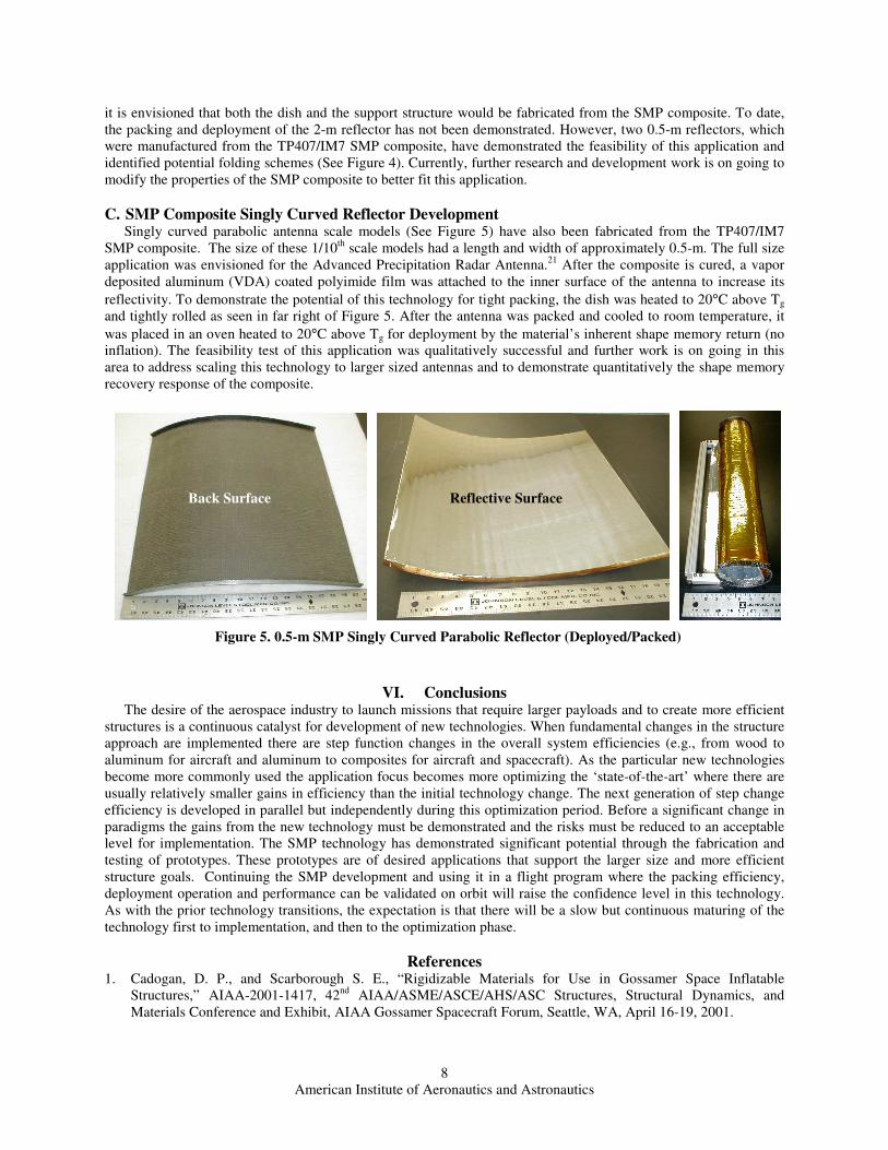
C. SMP Composite Singly Curved Reflector DevelopmentSingly curved parabolic antenna scale models (See Figure 5) have also been fabricated from the TP407/IM7
SMP composite. The size of these 1/10th
scale models had a length and width of approximately 0.5-m. The full size
application was envisioned for the Advanced Precipitation Radar Antenna.21
After the composite is cured, a vapor
deposited aluminum (VDA) coated polyimide film was attached to the inner surface of the antenna to increase its
reflectivity. To demonstrate the potential of this technology for tight packing, the dish was heated to 20°C above Tg
and tightly rolled as seen in far right of Figure 5. After the antenna was packed and cooled to room temperature, it
was placed in an oven heated to 20°C above Tg for deployment by the material’s inherent shape memory return (no
inflation). The feasibility test of this application was qualitatively successful and further work is on going in this
area to address scaling this technology to larger sized antennas and to demonstrate quantitatively the shape memory
recovery response of the composite.
VI. ConclusionsThe desire of the aerospace industry to launch missions that require larger payloads and to create more efficient
structures is a continuous catalyst for development of new technologies. When fundamental changes in the structure
approach are implemented there are step function changes in the overall system efficiencies (e.g., from wood to
aluminum for aircraft and aluminum to composites for aircraft and spacecraft). As the particular new technologies
become more commonly used the application focus becomes more optimizing the ‘state-of-the-art’ where there are
usually relatively smaller gains in efficiency than the initial technology change. The next generation of step change
efficiency is developed in parallel but independently during this optimization period. Before a significant change in
paradigms the gains from the new technology must be demonstrated and the risks must be reduced to an acceptable
level for implementation. The SMP technology has demonstrated significant potential through the fabrication and
testing of prototypes. These prototypes are of desired applications that support the larger size and more efficient
structure goals. Continuing the SMP development and using it in a flight program where the packing efficiency,
deployment operation and performance can be validated on orbit will raise the confidence level in this technology.
As with the prior technology transitions, the expectation is that there will be a slow but continuous maturing of the
technology first to implementation, and then to the optimization phase.
References1. Cadogan, D. P., and Scarborough S. E., “Rigidizable Materials for Use in Gossamer Space Inflatable
Structures,” AIAA-2001-1417, 42nd
AIAA/ASME/ASCE/AHS/ASC Structures, Structural Dynamics, and
Materials Conference and Exhibit, AIAA Gossamer Spacecraft Forum, Seattle, WA, April 16-19, 2001.
Reflective SurfaceBack Surface
Figure 5. 0.5-m SMP Singly Curved Parabolic Reflector (Deployed/Packed)
American Institute of Aeronautics and Astronautics
9
2. Scarborough S. E., and Cadogan, D. P., “Rigidizable Materials for Inflatable Space and Terrestrial Structures,”
SAMPE Symposium, Long Beach, CA, May 1-5, 2005.
3. “STEM™ Jib Antenna Data Sheet,” DS-201 07/04, Astro Aerospace, Northrop Grumman Space Technology,
2004.
4. “BI-STEM™ 40-lb Linear Actuator Data Sheet,” DS-414 07/04, Astro Aerospace, Northrop Grumman Space
Technology, 2004.
5. “Bi-Stable Reeled Composite (BRC),” RolaTube™ Technology Ltd., URL: http:rolatube.com/update/index.htm
[cited 17 April 2006].
6. Leipold, M., Runge, H., and Sickinger, C., “Large SAR Membrane Antennas with Lightweight Deployable
Booms,” 28th
ESA Antenna Workshop on Space Antenna Systems and Technologies, ESA/ESTEC, May 31 –
June 03, 2005.
7. Pellegrino, S., “Large Retractable Appendages in Spacecraft,” Journal of Spacecraft and Rockets, 0022-4650
Vol. 36, No. 6, 1995, pp. 1006-1014.
8. Murphy, D. M., Macy, B. D., and Gaspar, J. L., “Demonstration of a 10-m Solar Sail System,” AIAA-2004-
1576, 45th
AIAA/ASME/ASCE/AHS/ASC Structures, Structural Dynamics, and Materials Conference, 5th
AIAA Gossamer Spacecraft Forum, Palm Springs, CA, April 19-22, 2004.
9. “ADAM,” “CoilABLE,” and “Telescoping” Booms, ABLE Engineering, ATK Alliant Techsystems, URL:
http://www.aec-able/Booms/ablebooms.html [cited 17 April 2006].
10. “Innovative Space Spaced Radar Antenna Technology (ISAT),” Preliminary Design Review (PDR)
Presentation, Northrop Grumman Space & Mission Systems Corp., January 11-12, 2005.
11. “ALPHA Deployable Radiator Data Sheet,” Swales Aerospace, URL:
http://www.swales.com/pdf/deployrad.pdf [cited 17 April 2006].
12. Hachkowski, M. R., and Peterson, L. D., “A Comparative History of the Precision of Deployable Spacecraft
Structures,” CU-CAS-95-22, Center for Aerospace Structures, College of Engineering, University of Colorado,
Boulder, Colorado, 12/1995.
13. Tibert, G., “Deployable Tensegrity Structures for Space Applications,” Doctoral Thesis, Stockholm, 2002.
14. Younes, B., Zillig, D., Comberiate, A., Burns, M., and Chang, R., “NASA Future Operations at Ka-Band for
LEO Spacecraft Support,” Paper ID: 5a004, URL: http://track.sfo.jaxa.jp/spaceops98/paper98/track5/5a004.pdf
[cited 17 April 2006].
15. Miura, K., and Miyazaki, Y., “Concept of the Tension Truss Antenna,” AIAA Journal, Vol. 28, No. 6, 1990, pp.
1098-1104.
16. “AstroMesh™ Deployable Reflector Data Sheet,” DS-409 07/04, Astro Aerospace, Northrop Grumman Space
Technology, 2004.
17. Thomson, M., “AstroMesh™ Deployable Reflectors for Ku and Ka Band Commercial Satellites,” AIAA-2002-
2032, 20th
AIAA International Communication Satellite Systems Conference and Exhibit, Montreal, Quebec,
May 12-15, 2002.
18. Chmielewski, A. B., Noca, M., and Wietfeldt, R. D. (editors), ARISE Advanced Radio Interferometry between
Space and Earth – Mission and Spacecraft, 2nd
ed., JPL99-14, Jet Propulsion Laboratory, Pasadena, California,
October 1999, Chap. 4.

American Institute of Aeronautics and Astronautics
10
19. Freeland, R. E., and Veal, G. R., “Significance of the Inflatable Antenna Experiment Technology,” AIAA-
1998-2104, 39th
AIAA/ASME/ASCE/AHS/ASC Structures, Structural Dynamics, and Materials Conference
and Exhibit, and AIAA/ASME/AHS Adaptive Structures Forum, Long Beach, CA, April 20-23, 1998.
20. Willey, C. E., Bokulic, R. S., Skullney, W. E., Cadogan, D. P., and Lin, J. K., “The Hybrid Inflatable Antenna,”
AIAA-2001-1258, 42nd
AIAA/ASME/ASCE/AHS/ASC Structures, Structural Dynamics, and Materials
Conference and Exhibit AIAA Gossamer Spacecraft Forum, Seattle, WA, April 16-19, 2001.
21. Lin, J. K., Sapna, G. H., Scarborough, S. E., and Lopez, B. C., “Advanced Precipitation Radar Antenna Singly
Curved Parabolic Antenna Reflector Development,” AIAA-2003-1651, 44th
AIAA/ASME/ASCE/AHS/ASC
Structures, Structural Dynamics, and Materials Conference and Exhibit, AIAA Gossamer Spacecraft Forum,
Norfolk, VA, April 7-10, 2003.