Embed Size (px)
Citation preview
PERGAMON
INTERNATIONAL JOURNAL OF
IMPACT ENGINEERING
International Journal of Impact Engineering 26 (2001) 699-711 www.elsevier.com/loeate/ijimpeng
SHAPE EFFECTS IN HYPERVELOCITY IMPACT ON SEMI-INFINITE METALLIC TARGETS
FRANK K. SCHA~ER, MICHAEL HERRWERTH, STEFAN J. HIERMAIER and EBERHARD E. SCHNEIDER
Emst-Mach-lnstitut - Fraunhofer Institut fiir Kurzzeitdynamik, Eckerstr. 4, D - 79104 Freiburg i. Br., Germany
Abstract--In this study, an existing penetration equation, which was originally designed to give the penetration depth of spherical projectiles at hypervelocity into semi-infinite metallic targets, was modified to give the penetration depths of rotationally symmetric ellipsoid shaped projectiles into semi-infinite targets. To that purpose, a shape factor was defined in order to be able to describe the ellipsoid shape with a single number. The shape factor corresponds to the I/d ratio of rod- or disk-like projectiles. It was shown, that existing penetration equations can be modified to account for the shape of the projectile by introducing a single factor f n. From the experimental and simulation data available in this study, n=0.45 was derived as a suitable exponent to describe the shape effect. In addition to the experiments numerical simulation was performed to enhance the data base and to show it's value for further investigations of the shape effect. © 2001 Elsevier Science Ltd. All rights reserved.
Keywords: hypervelocity impact, semi-infinite target, penetration equation, shape effect, ellipsoid shaped projectile, shape factor, numerical simulation
a, b, c
C d f H n
P~ V
V n
Pp
P,
NOTATION
semi-ax i s of e l l ipsoid ve loc i ty of sound [km/s] pro jec t i le d iamete r [cm]
shape fac tor (c/a = c/b = l/d) [-] Br inel l Hardness of target [-]
exponent desc r ib ing dependence on shape fac tor [-]
penet ra t ion depth in semi- inf in i te target [cm] ve loc i ty [km/s] normal componen t of pro jec t i le ve loc i ty [km/s]
projec t i le dens i ty [g/cm 3]
target dens i ty [g/cm 3]
0734-743X/01/$ - see front matter © 2001 Elsevier Science Ltd. All rights reserved. PII: S 0 7 3 4 - 7 4 3 X ( 0 1 ) 0 0 1 1 5 - 4

700 EK. Schiifer et al. / International Journal of lmpact Engineering 26 (2001) 699-711
INTRODUCTION
The current penetration and damage equations for hypervelocity impacts of metallic projectiles on semi-infinite targets, thin plates and Whipple shields are based on spherical impactors. Shape is not considered in any damage equation. From impact tests with non- spherical geometries like thin flyer plates and inhibited shaped charges or rod impact it is well known that shape influences strongly type and extent of the damage (see [1 ] - [5 ]). However, there exists no publication giving an equation that describes the shape effect in a general manner.
Risk analysis tools for spacecraft survivability calculations like ESABASE/DEBRIS from ESA or BUMPER from NASA rely on the quality of the damage and penetration equations implemented. Currently these damage equations are based on spherical impactors only. Also, the requirements concerning the Probability of No Penetration (PNP) that have to be fulfilled by the spacecraft structures in any mission are based on spherical impactors. As stated above, shape has a major impact on the penetration performance of a projectile. Considering only spherical projectiles thus leads to systematically wrong predictions by the analysis tools in use today. It is obvious that in general the introduction of the shape in the penetration equations reduces the PNP for a given structure.
The purpose of this study is to present an approach to cope with the shape effects in the penetration equations in semi-infinite targets. In order to have a single parameter that describes the shape, the projectiles were of ellipsoid shape. This parameter was called the shape factor and corresponds to the 1/d ratio of cylindrical projectiles.
A series of tests was performed on semi-infinite targets. Penetration equations, based on Cour-Palais' formula, that include the shape factor, are presented for semi-infinite metallic targets.
SHAPE FACTOR
The projectiles were of ellipsoid shape. Ellipsoids are fully described by the three semi-axis a, b, and c (Fig. 1). In Fig. 1 the z-Axis is the shot direction. In this study, only "regular" ellipsoids are considered, having at least two equal semi-axis. In the following, three types of ellipsoids are distinguished:
Type I: sphere a = b = c Type II: prolate ellipsoid a = b < c Type III: oblate ellipsoid a = b > c
Y
Fig. 1 Ellipsoid.
F.K. Schiifer et al. / International Journal of Impact Engineering 26 (2001) 699-711 701
In order to describe the deviation from the spherical shape with a single factor, the so-called shape factor was introduced. As the transversal semi-axis a and b are selected equal, the shape factor can be defined by the ratio of c to a (or b). Even more general, the shape factor becomes the ratio of length I = 2c of the ellipsoid to its diameter d = 2a = 2b.
Shape factor for ellipsoid projectiles: f = / d
Thus, spherical projectiles, which are the reference projectile shapes, have a shape factor f --- 1, prolate ellipsoids have a shape factor f > 1 and oblate ellpsoids have a shape factor f < 1. In Fig. 2 the shape factor is plotted for a reference spherical projectile diameter of 6 mm as a function of the ellipsoid diameter. Having a constant volume elllipsoid, large shape factors are achieved when the ellipsoid diameter is reduced or increased. For example, reducing the diameter of the ellipsoid from 6 mm to 3 mm (i.e., by a factor of 2) raises the shape factor f from 1 to 8. Increasing the diameter by a factor of two from 6 mm to 12 mm reduces the shape factor to 0.125.
Z
'6
9 -
8- 7
6
5
4
3
2-"
s h a p e f ac to r as a f u n c t i o n of d i a m e t e r
Ilipsold A " • ' oblate ellipsoid
f
0 , , , , , , . .
2 3 4 5 6 7 8 9 10 1 2 diameter d [ram]
C__ ljl
Fig. 2 Shape factor f , plotted as a function of the ellipsoid diameter. The reference volume is that of a 6 mm diameter sphere.
PROJECTILES AND TARGETS
The projectiles were made from AI 2017 alloy (AICuMgl), having a yield strength of ca. 265 MPa, an upper tensile strength of 390 MPa, maximum elongation of 13 % and a Brinell Hardness of 100 (manufacturer data). They were machined from bulk material on a CNC. The reference volume of the ellipsoid projectiles was chosen to be that of a 6 mm diameter sphere. The corresponding mass was 316 mg. The projectile measures are given in Table 1. Photos of the projectiles and the corresponding sabots are shown in Fig. 3.
702 EK. Schiifer et al. /International Journal of lmpact Engineering 26 (2001) 699-711
Table 1. Ellipsoid projectile types
Projectile Type Diameter length mass shape factor [mml [mml [mgl [-1
S-I 6.0 316 1 EL-II 5.2 8.0 316 1.539 LE-III 8.0 3.38 316 0.423 EL-IV 4.25 12.0 316 2.824 EL-V 3.68 16.0 316 4.348 LE-VI 10.0 2.16 316 0.216 LE-VII 12.0 1.5 316 0.125
Type I
Type II
Type III
Type Sabot (section) Sabot (top view) and projectile (front and side views)
Fig. 3 Projectiles and corresponding sabot shapes.
The targets were semi-infinite aluminium blocks. The semi-infinite targets were made of A1 2007 (A1CuMgPb), having a thickness of 50 mm (Fig. 4).
Fig. 4 Semi-infinite target, top view, with an impact crater.
El(,. Schi~fer et al. / International Journal of lmpact Engineering 26 (2001) 699-711 703
IMPACTS ON SEMI-INFINITE METALLIC TARGETS
The impact tests were performed on the two-stage light-gas guns of the Emst-Mach-Institute, Freiburg ([6 ], [7 ]). Purpose of the impact tests on semi-infinite targets was the modification of existing penetration equations by considering the projectile shape, i. e. the shape factor f of ellipsoid shaped projectiles. Five impact tests on semi-infinite targets were performed and the penetration depths were recorded.
The test matrix is given in Table 2. Impact velocities were between 3.4 and 5.3 km/s. Besides the test parameters the inclination angle of the projectile axis with respect to the shot axis and the penetration depth in the semi-infinite target are provided. Concerning the inclination angle of the projectile prior to impact, pitch and yaw angle need to be determined. However, the projectile was only photographed in single high-speed video shadowgraphs. Consequently, only yaw can be measured directly from the photographs. In order to determine the pitch, an indirect procedure was followed: The apparent L/D ratio was measured form the apparent length of the projectile and its apparent diameter on the pictures. Comparing the apparent L/D to the actual L/D yields then the pitch angle. The angles provided in Table 2 refer to the actual inclination angle of the projectile with respect to the shot axis. Some examples of the shadowgraphs used for determination of the inclination angle with respect to the z-axis are presented in Fig. 5. As can be seen in the test matrix, there was only one test out of four of the ellipsoid shaped projectiles where the projectile axis was oriented exactly along the shot axis. This is related to lack of symmetry in the release of the projectiles from the sabot parts in the blast tank, introducing in most cases a slight torque. Technologically, it is hardly feasible to reach inclination angles of 0 ° in all tests. For what concerns the evaluation of the data, only those data points were selected where the inclination angle was below 10 °. As expected, the deepest craters were generated by the prolate ellipsoid, though the conditions are not directly comparable to the oblate ellipsoid due to slight differences in the impact velocities. The crater shapes for each of the each projectile type are plotted in Fig. 6.
Table 2 Test matrix for the impacts on semi-infinite targets and penetration depths EMI No. Exp./Sim No. Geometry v inclination Penetration depth
angle Type [km/s] [ °] [mm]
3807 1 SP-I 5,3 - 9,85 3808 2 Prol.-EL-II 4,5 28 10 3809 3 Prol.-EL-II 4,3 0 10,75 3814 4 Prol.-EL-II 3,4 45 8,2 3816 5 Obl.-EL-III 3,5 5 5,6

704 EK. Schiifer et al. /International Journal of Impact Engineering 26 (2001) 699-711
Type I (No. 1, 3807)
Type II (No. 2, 3808)
Type II (No. 3, 3809)
Type III (No. 5, 3816)
/
Shadowgraph of projectile-in-flight shortly before impact (flight direction:
from right to left)
Magnified view of the projectile-in-flight used for the determination of the inclination
angle of the projectile with respect to the shot axis
Fig. 5 Shadowgraphs of projectiles-in-flight.
F.K. Schiifer et al. / International Journal of lmpact Engineering 26 (2001) 699-711 705
Type I (No. 1, 3807)
Type II (No. 3, 3809)
Type III (No. 5, 3816)
Fig. 6 Crater shapes as a function of the projectile shape.
NUMERICAL SIMULATION
For the semi infinite impact test No. 1, 3 and 5 numerical simulations have been performed using the hydrocodes AUTODYN-2D in axisymmetric mode and AUTODYN-3D. As the deep penetration into a massive target is a mainly hydrodynamically dominated process, material failure models are of secondary importance. Thus a shock equation of state and a yon Mises yield model was used for the calculations. In order to simulate the crater forming process with finite difference cells an erosion criterion has been used to convert highly distorted cells into mass points. This conversion occurred at a strain threshold of 250 %.
For the ellipsoids with short lengths and large diameters a normal impact is hard to achieve in the experiments. Actually it is very likely to get yaw or pitch angles. In order to model these angles the oblate ellipsoid impacts were modeled in 3D with one symmetry plane.
Figure 7 shows a pressure contour plot during the penetration of the EL-II projectile in to the semi-infinite target.
706 F..K. Sch~ifer et al. / International Journal of Impact Engineering 26 (2001) 699-711
Fig. 7 Pressure contour plot for projectile EL-II penetrating the semi-infinite target.
Calculated crater profiles are shown in figure 8, the related data on penetration depths are given in table 3. The simulation was stopped when the target showed a homogeneous velocity distribution. All these results show a clear influence of the projectile shape on penetration behavior as seen before in the experimental results.
O Fig. 8
o 0 Calculated impact craters for the different shapes.
EK. Schitfer et al. / International Journal of lmpact Engineering 26 (2001) 699-711 707
Table 3: Comparison of measured and calculated penetration depths for semi infinite targets
Geometry
Sphere SP-I Prol.-EL-II
Prol.-EL-IV
Prol.-EL-V
Obl.-EL-III
Obl.-EL -VI Obl.-EL -VII
Impact Velocity [km/s]
5.3 2.5 3.5 4.3 6.0 3.5 4.3 3.5 4.3 3.5
3.5 3.5
Experiment
(Test No. 1) 9.85
(Test No. 3) 10.75
Penetration depth [mm]
(Test No. 5) 5.6
2D 9.8 7.4 9.4 11.2 14.3 11.9 13.8 14.1 16.8
4,5 2,6
Simulation 3D
5.4 (0 °) 5.15 (S °) 5.0 (10 °) 4.7 (15 ° ) 8.9 (450)
Comparing the numerical results concerning the crater depth with the experimental ones shows variations of about 5 % and are considered acceptable.
The fact that the simulation of more or less deep penetration into semi infinite targets gives good results is not surprising. The reason to perform the simulation was to show that the numerical tools can and should be used to further investigate the shape effects during hypervelocity impact. A lot more parameter studies could be performed by simulation. Not only for the experiments performed anyway but also for cases where experiments are in some way limited. For instance angles of attack, defined rotation speed, more complex shape that can hardly be accelerated by light gas guns and other circumstances leading to experimental problems. A close cooperation of experimental tests and numerical simulation is the key to get much more information on this important issue with reasonable efforts.
DERIVATION OF MODIFIED PENETRATION EQUATION
A commonly used penetration equation for semi-infinite targets giving the penetration depth as a function of normal impact velocity, projectile diameter, projectile and target density, and the target's Brinell Hardness is the Cour-Palais equation (Equation 1 [8 ]). It is the equation that is being referred to in the following. However, the derivation of the modified penetration equation can generally be performed for any other penetration equation.
1 2
f.01 (Original Cour-Palais equation) (1)
The fit coefficient in Equation 1 is a material and batch dependent constant which was determined from fitting experimental data to the parameters of the equation. The Cour-Palais
708 F.K. Schiifer et al. /International Journal of lmpact Engineering 26 (2001) 699-711
equation and the experimental data are plotted in the diagram in Figure 9 as a function of impact velocity. The large symbols correspond to the experimental data that were used for fitting the equation in a procedure described hereafter. The smaller symbols correspond to the experimental penetration depths from impact of prolate ellipsoids that had an inclination angle of more than 10 °.
In a first step, the fit-coefficient in the Cour-Palais equation was adjusted to predict precisely the penetration depth obtained from the impact test involving the spherical projectile. Thus it was ensured, that the equation was capable to describe the penetration depths into the Al-alloy used in this test series. The coefficient was determined to be 5.52 thus about 5 % larger than the original Cour-Palais coefficient (Equation 2). The adjusted Cour-Palais equation (Equation 2) is plotted together with the original Cour-Palais equation (Equation 1) into Figure 10.
1 2
P==5.52 .d~ .H ¼ / pp/~ (~.~--~)' "L-~-t ) ' (Adjusted Cour-Palais equation) (2)
16-
14. 12-
E io. r"
Q .
~ 8
0 = 6
~ 4 C
Q.
2
0 0
Cour-Palais • sphere
(inclination angles with respect to shot axis)
• prolate ellipsoid 0 ° • • prolate ellipsoid 28 ° -" • prolate el.lipsoid 41 ° •
I I I I I
2 3 4 5 6 7
velocity [km/s]
Fig. 9 Experimental data: Penetration depth for the different shapes plotted versus impact velocity; semi-empirical equation of Cour-Palais plotted for comparison
The next step was the determination of the functional dependence of the penetration depth on the shape factor. A general approach was selected: Assuming the penetration behaviour of shapes differing from spherical can also be described with the same basic parametrical dependence as in the original Cour-Palais equation for spheres, it is reasonable to assume the shape effect can be described by an additional factor, say f ". f is the shape factor as defined previously, n is an arbitrary exponent to be fitted in the tests, n should be chosen such that it is capable to describe the penetration depth P(v) for shapes having a shape factor in excess of 1 and below 1, i.e. it should hold for the prolate and the oblate ellipsoids.
It is thus stated that the general form of the equation is:
EK. Schiifer et al. / International Journal of lmpact Engineering 26 (2001) 699-711 709
P(v)=P~(v).f" (3)
The dependence of the penetration depth on velocity is highlighted in Equation 3. Equation 3 is readily solved for the unknown exponent n:
r l = log(f)
P=(v) is known from Equation 2, all that remains to do is to insert into Equation 4 the shape factor for the considered shape and the corresponding P(v). The best fit for n to all experimental and numerical data points yielded 0.45. The resulting modified penetration equation is:
19 -1 1 2
~ : ~. ~ . d , ~ . . ~ . / ~ ~ ~ . (~1~. fo ~ k Pt .)
(5)
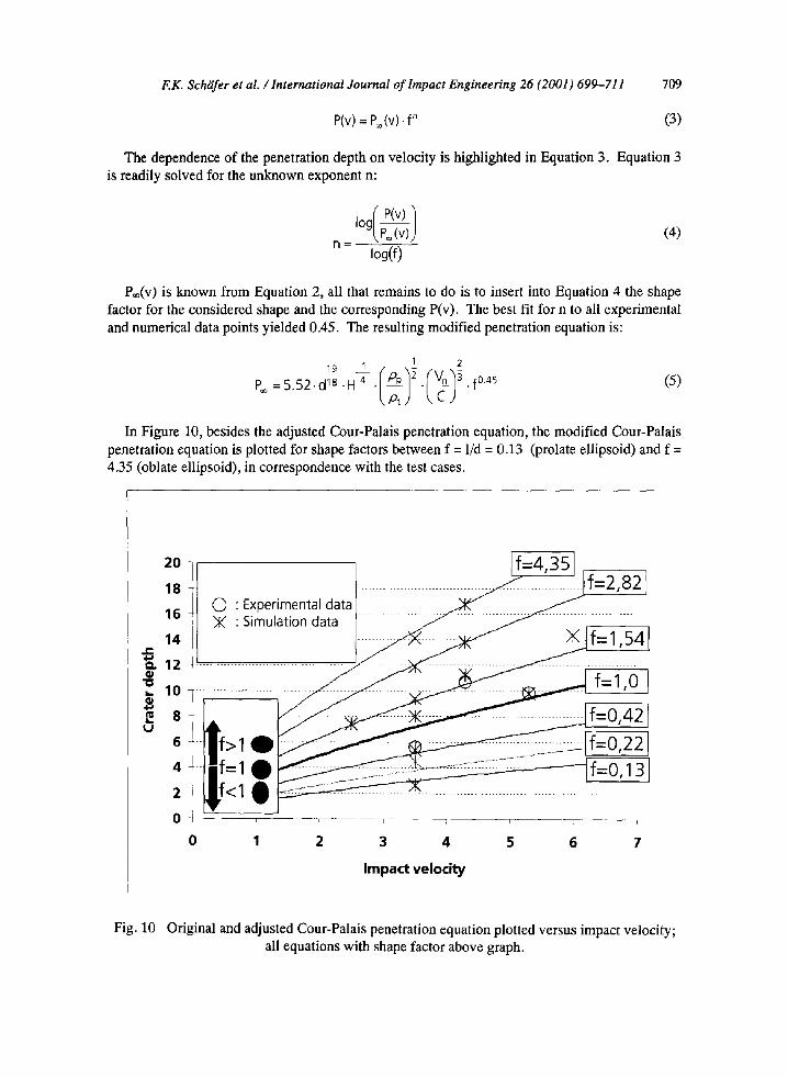
In Figure 10, besides the adjusted Cour-Palais penetration equation, the modified Cour-Palais penetration equation is plotted for shape factors between f = 1/d = 0.13 (prolate ellipsoid) and f = 4.35 (oblate ellipsoid), in correspondence with the test cases.
20 f=4,35 f
0 • Experimental d a t a x x . Simulation data i i i i i i i i i i i i i ~ ~ ]
. . . . . . . . . . . . . . . . . . . . . . . . . . . . . . . . . . . . .
................................. J f = l , 0 / f-o,4 > f=0,22
18
16
Q. 12 < . . . . . . . . . . . . . . . . . . . . . "O ,. 10 ............
6 -- f > l
4 - - 1 . . . . . . . . . . . . • . . . . . . . . . . . . -.==c-::::::i_- . . . . . .
, - |f:~l O - i ] • T
0 1 2 3 4 5 6 7
Impact velocity
Fig. 10 Original and adjusted Cour-Palais penetration equation plotted versus impact velocity; all equations with shape factor above graph.
7 1 0 EK. Schlifer et al. /International Journal of lmpact Engineering 26 (2001) 699-711
DISCUSSION AND CONCLUSIONS
In this study, the Cour-Palais penetration formula was modified in a way that it is capable to give the shape dependent penetration depth of hypervelocity projectiles into semi infinite metallic targets. It was shown that the existing version of the penetration formula can be adjusted by a shape factor to the power of n. Where n is the exponent that was fit experimentally to a value of 0.45. The number of tests that were available to derive this result is small. The reason is the big efforts to manufacture both the non-spherical projectiles and the related sabots and the performance of the impact tests.
To overcome this problem additional numerical simulations have been performed. The model was validated with the existing experimental data. Using the same material data for all simulations a reliable database for shape factors between 0.125 and about 4.5 was achieved. Generally good agreement between experimental and numerical results could be shown. Thus it is reasonable to assume that the penetration formula derived is valid for shape factors in the simtdated regime at least to a first order.
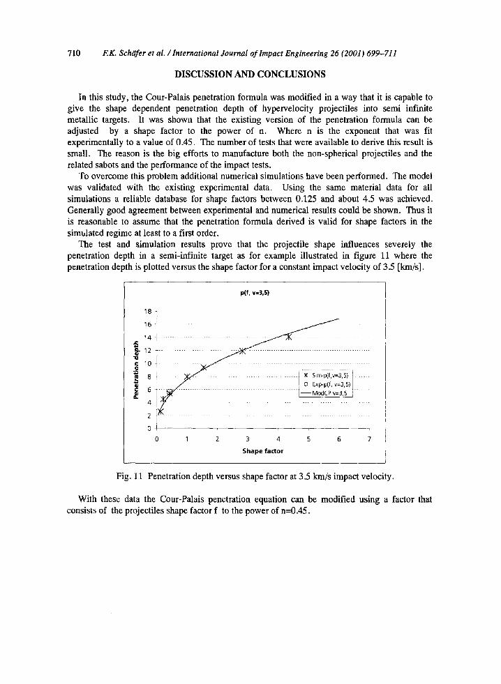
The test and simulation results prove that the projectile shape influences severely the penetration depth in a semi-infinite target as for example illustrated in figure 11 where the penetration depth is plotted versus the shape factor for a constant impact velocity of 3.5 [km/s].
p(f, v=3,5)
18-]
. - 10
0 1211 I;;i!IZIZZZ211ZZ211ZIII, IZI 4
2 I
0 +
0 1 2 3 4 5 6 7
Shape factor
Fig. 11 Penetration depth versus shape factor at 3.5 km/s impact velocity.
With these data the Cour-Palais penetration equation can be modified using a factor that consists of the projectiles shape factor f to the power of n=0.45.

F.K. Schgifer et al. /International Journal of Impact Engineering 26 (2001) 699-711
REFERENCES
711
[1] Gehring, JW. Engineering Considerations In Hypervelocity Impact, Pages 463-514 In: R. Kinslow High- Vclocity Impact Phenomena, New York-London, Academic Press, 1970.
[2] Denardo, P. Projectile Shape Effects On Hypervelocity Impact Craters In: Aluminum, Ames Research Center, NASA, Moffett Field, Calif. 94035, Sept. 11, 1968.
[3] Konrad CH, Chhabildas LC, Boslough MB, Pietkutowski A. J., Poormon K. L., Mullin S. A., Littlefield DL. Dependence Of Debris Could Formation On Projectile Shape. High-Pressure Science and Technology, 1993, p. 1845-1848.
[4] Bjerke, TW., Zukas, JA., Kimsey K. D. Penetration Performance Of Disk Shaped Penetrators, Int. J. of Impact Engng, 1992; 12(2):263-280.
[5] Orphal, D.L., Anderson Jr., D. E., Franzen R. R., Babcock S. M. Variation of Crater Geomatry With Projectile L/D For L/D<I, Int. J. oflmpact Engng, 1995; 17:595-604.
[6] Crozier WD, Hume W. High Velocity Light Gas Gun.J. ofAppl. Phys.,1957; 28. [7] Stilp A. Review of Modem Hypervelocity Impact Facilities. Int. J. oflmpact Engng., 1987; 5. [8] Ch ristiansen EL. Design And Performance Equations For Advanced Meteroid And Debris Shields. Int. J.
of lmpact Engng, 1993; 14:145-156.


![ɷ[haym kruglak, john moore, ramon mata toledo] scha](https://img.pdfslide.us/doc/110x75/568cab711a28ab186da59571/haym-kruglak-john-moore-ramon-mata-toledo-scha.jpg)