Embed Size (px)
Citation preview

Shanghai Slam tec Co., Ltd.www.slamtec.com
RPLIDAR A2 Low Cost 360 Degree Laser Range Scanner
Introduction and Datasheet
Model: A2M3
A2M4
2016-04-28 rev.06
OPTMAG 4K

CONTENTS ................................................................................................................................................... 1
1. INTRODUCTION ................................................................................................................................. 3
SYSTEM CONNECTION ........................................................................................................................................ 4
MECHANISM ....................................................................................................................................................... 5
SAFETY AND SCOPE ............................................................................................................................................ 6
DATA OUTPUT .................................................................................................................................................... 6
HIGH SPEED SAMPLING PROTOCOL AND COMPATIBILITY ................................................................................. 7
APPLICATION SCENARIOS ................................................................................................................................... 8
2. SPECIFICATION .................................................................................................................................. 9
MEASUREMENT PERFORMANCE ......................................................................................................................... 9
LASER POWER SPECIFICATION .......................................................................................................................... 10
OPTICAL WINDOW ........................................................................................................................................... 10
COORDINATE SYSTEM DEFINITION OF SCANNING DATA ................................................................................ 11
COMMUNICATION INTERFACE .......................................................................................................................... 11
POWER SUPPLY INTERFACE .............................................................................................................................. 12
DATA COMMUNICATION INTERFACE ................................................................................................................ 13
SCANNER MOTOR CONTROL ........................................................................................................................... 14
MISC ................................................................................................................................................................ 14
3. SELF-PROTECTION AND STATUS DETECTION ......................................................................... 15
4. SDK AND SUPPORT ........................................................................................................................ 16
5. MECHANICAL DIMENSIONS ......................................................................................................... 17
6. REVISION HISTORY ......................................................................................................................... 18
APPENDIX .................................................................................................................................................. 19
IMAGE AND TABLE INDEX ................................................................................................................................. 19

3 / 19
Copyright (c) 2009-2013 RoboPeak Team
Copyright (c) 2013-2016 Shanghai Slamtec Co., Ltd.
The RPLIDAR A2 is the next generation low cost 360 degree 2D laser scanner
(LIDAR) solution developed by SLAMTEC. It can take up to 4000 samples of laser
ranging per second with high rotation speed. And equipped with SLAMTEC
patented OPTMAG technology, it breakouts the life limitation of traditional LIDAR
system so as to work stably for a long time.
The system can perform 2D 360-degree scan within a 6-meter range. The
generated 2D point cloud data can be used in mapping, localization and
object/environment modeling.
The typical scanning frequency of the RPLIDAR A2 is 10hz (600rpm). Under this
condition, the resolution will be 0.9°. And the actual scanning frequency can be
freely adjusted within the 5-15hz range according to the requirements of users.
The RPLIDAR A2 adopts the low cost laser triangulation measurement system
developed by SLAMTEC, which makes the RPLIDAR A2 has excellent performance
in all kinds of indoor environment and outdoor environment without direct
sunlight exposure. Meanwhile, before leaving the factory, every RPLIDAR A2 has

4 / 19
Copyright (c) 2009-2013 RoboPeak Team
Copyright (c) 2013-2016 Shanghai Slamtec Co., Ltd.
passed the strict testing to ensure the laser output power meet the standards of
FDA Class I.
System connection
The RPLIDAR A2 consists of a range scanner core and the mechanical powering
part which makes the core rotate at a high speed. When it functions normally, the
scanner will rotate and scan clockwise. And users can get the range scan data via
the communication interface of the RPLIDAR and control the start, stop and
rotating speed of the rotate motor via PWM.
Figure 1-1 RPLIDAR System Composition
The RPLIDAR A2 comes with a rotation speed detection and adaptive system. The
system will adjust the angular resolution automatically according to the actual
rotating speed. And there is no need to provide complicated power system for
RPLIDAR. In this way, the simple power supply schema saves the BOM cost. If the
actual speed of the RPLIDAR is required, the host system can get the related data
via communication interface.
The detailed specification about power and communication interface can be
found in the following sections.
Range Scanner Core
Mechanical
Powering Part
Communication and
Power Interface

5 / 19
Copyright (c) 2009-2013 RoboPeak Team
Copyright (c) 2013-2016 Shanghai Slamtec Co., Ltd.
Mechanism
The RPLIDAR A2 is based on laser triangulation ranging principle and adopts the
high-speed vision acquisition and processing hardware developed by SLAMTEC.
The system ranges more than 4000 times per second.
Figure 1-2 The RPLIDAR Working Schematic
During every ranging process, the RPLIDAR emits modulated infrared laser signal
and the laser signal is then reflected by the object to be detected. The returning
signal is then sampled by vision acquisition system in RPLIDAR and the DSP
embedded in RPLIDAR starts processing the sample data and outputs distance
value and angle value between object and RPLIDAR via communication interface.
When drove by the motor system, the range scanner core will rotate clockwise
and perform the 360-degree scan for the current environment.
𝐝

6 / 19
Copyright (c) 2009-2013 RoboPeak Team
Copyright (c) 2013-2016 Shanghai Slamtec Co., Ltd.
Figure 1-3 The Obtained Environment Map from RPLIDAR Scanning
Safety and Scope
The RPLIDAR A2 system uses a low power infrared laser as its light source, and
drives it by using modulated pulse. The laser emits light in a very short time
frame which can ensure its safety to human and pet, and it reaches Class I laser
safety standard.
The modulated laser can effectively avoid the interference from ambient light
and sunlight during ranging scanning process, which makes RPLIDAR work
excellent in all kinds of indoor environment and outdoor environment without
sunlight.
Data Output
During the working process, the RPLIDAR will output the sampling data via the
communication interface. And each sample point data contains the information in
*Note:The LIDAR scan image is not
directly relative to the environment
showed here. Illustrative purpose only.
Class I

7 / 19
Copyright (c) 2009-2013 RoboPeak Team
Copyright (c) 2013-2016 Shanghai Slamtec Co., Ltd.
the following table. If you need detailed data format and communication protocol,
please contact SLAMTEC.
Figure 1-4 The RPLIDAR Sample Point Data Information
Figure 1-5 The RPLIDAR Sample Point Data Frames
The RPLIDAR outputs sampling data continuously and it contains the sample point
data frames in the above figure. Host systems can configure output format and
stop RPLIDAR by sending stop command. For detailed operations please contact
SLAMTEC.
High Speed Sampling Protocol and Compatibility
The RPLIDAR A2 adopts the newly extended high speed sampling protocol for
outputting the 4000 times per second laser range scan data. Users are required to
update the matched SDK or modify the original driver and use the new protocol
to use the 4000 times per second mode of RPLIDAR A2. Please check the related
protocol documents for details.
The RPLIDAR A2 is compatible with all the communication protocols of previous
versions. Users can directly replace the previous RPLIDAR with RPLIDAR A2 and
Data Type Unit Description
Distance mm Current measured distance value between the rotating
core of the RPLIDAR and the sampling point
Heading degree Current heading angle of the measurement
Start Flag (Bool) Flag of a new scan
Checksum The Checksum of RPLIDAR return data
… (dሾn − 1ሿ, θሾn − 1ሿ) (dሾnሿ, θሾnሿ) (dሾ0ሿ, θሾ0ሿ) (dሾ1ሿ, θሾ1ሿ)
…
Start Flag
A new scan

8 / 19
Copyright (c) 2009-2013 RoboPeak Team
Copyright (c) 2013-2016 Shanghai Slamtec Co., Ltd.
use it in the original system. But in this scenario, the RPLIDAR A2 will work in
compatible mode and the system will take range 2000 times per second.
Application Scenarios
The RPLIDAR can be used in the following application scenarios:
o General robot navigation and localization
o Environment scanning and 3D re-modeling
o Service robot or industrial robot working for long hours
o Home service /cleaning robot navigation and localization
o General simultaneous localization and mapping (SLAM)
o Smart toy’s localization and obstacle avoidance

9 / 19
Copyright (c) 2009-2013 RoboPeak Team
Copyright (c) 2013-2016 Shanghai Slamtec Co., Ltd.
Measurement Performance
For Model A2M3/A2M4 Only
Figure 2-1 RPLIDAR Performance
Note: the triangulation range system resolution changes along with distance, and
the theoretical resolution change of RPLIDAR is shown as below:
Figure 2-2 The Trend Graph of RPLIDAR Resolution
0.00%
0.02%
0.04%
0.06%
0.08%
0.10%
0.12%
0.14%
0.16%
0.18%
0.20%
0
2
4
6
8
10
12
10
25
0
49
0
73
0
97
0
12
10
14
50
16
90
19
30
21
70
24
10
26
50
28
90
31
30
33
70
36
10
38
50
40
90
43
30
45
70
48
10
50
50
52
90
55
30
57
70
60
10
Resoultion
Precent
Item Unit Min Typical Ma
x Comments
Distance
Range Meter(m) TBD 0.15 - 6
TB
D White objects
Angular
Range Degree n/a 0-360 n/a
Distance
Resolution mm n/a
<0.5 n/a
<1.5 meters
<1% of the distance All distance range*
Angular
Resolution Degree 0.45 0.9
1.3
5 10Hz scan rate
Sample
Duration Millisecond(ms) n/a 0.25 n/a
Sample
Frequency Hz 2000 ≥4000
410
0
Scan Rate Hz 5 10 15
Typical value is measured
when RPLIDAR takes 400
samples per scan

10 / 19
Copyright (c) 2009-2013 RoboPeak Team
Copyright (c) 2013-2016 Shanghai Slamtec Co., Ltd.
Laser Power Specification
For Model A2M3/A2M4 Only
Figure 2-3 RPLIDAR Optical Specification
Note: the laser power listed above is the peak power and the actual power is much
lower than the value.
Optical Window
To make the RPLIDAR A2 working normally, please ensure proper space to be left
for its emitting and receiving laser lights when designing the host system. The
obscuring of the host system for the ranging window will impact the performance
and resolution of RPLIDAR A2. If you need cover the RPLIDAR A2 with translucent
materials or have other special needs, please contact SLAMTEC about the
feasibility.
Figure 2-4 RPLIDAR Optical Window
You can check the Mechanical Dimensions chapter for detailed window
dimensions.
Item Unit Min Typical Max Comments
Laser
wavelength Nanometer(nm) 775 785 795
Infrared Light
Band
Laser power Milliwatt (mW) TBD 3 5 Peak power
Pulse length Microsecond(us) 60 87 90
Laser Safety
Class FDA Class I
Optical Window

11 / 19
Copyright (c) 2009-2013 RoboPeak Team
Copyright (c) 2013-2016 Shanghai Slamtec Co., Ltd.
Coordinate System Definition of Scanning Data
The RPLIDAR A2 adopts coordinate system of the left hand. The dead ahead of
the sensors is the x axis of the coordinate system; the origin is the rotating center
of the range scanner core. The rotation angle increases as rotating clockwise. The
detailed definition is shown in the following figure:
Figure 2-5 RPLIDAR Scanning Data Coordinate System Definition
Communication interface
The RPLIDAR A2 uses separate 5V DC power for powering the range scanner core
and the motor system. And the standard RPLIDAR A2 uses XH2.54-5P male socket.
Detailed interface definition is shown in the following figure:
θ ሾ0,360)
Interface Lead

12 / 19
Copyright (c) 2009-2013 RoboPeak Team
Copyright (c) 2013-2016 Shanghai Slamtec Co., Ltd.
Figure 2-6 RPLIDAR Power Interface Definition
Figure 2-7 RPLIDAR External Interface Signal Definition
Power Supply Interface
RPLIDAR A2 takes the only external power to power the range scanner core and
the motor system which make the core rotate. To make the RPLIDAR A2 work
normally, the host system needs to ensure the output of the power and meet its
requirements of the power supply ripple.
Color Signal Name Type Description Min Typical Max
Red VCC Power Total Power 4.9V 5V 5.5V
Yellow TX Output Serial port output of the
scanner core 0V 3.3V 3.5V
Green RX Input Serial port input of the
scanner core 0V 3.3V 3.5V
Black GND Power GND 0V 0V 0V
Blue MOTOCTL Input
Scan motor /PWM
Control Signal(active
high, internal pull
down)
0V 3.3V 5V
Red
XH2.54-5P
VC
C
TX
RX
GN
D
MO
TO
CT
L

13 / 19
Copyright (c) 2009-2013 RoboPeak Team
Copyright (c) 2013-2016 Shanghai Slamtec Co., Ltd.
For Model A2M3/A2M4 Only
Figure 2-8 RPLIDAR Power Supply Specification
Data communication interface
The RPLIDAR A2 takes the 3.3V-TTL serial port (UART) as the communication
interface. The table below shows the transmission speed and the protocol
standard.
Figure 2-9 RPLIDAR Serial Port Interface Specifications
Item Unit Min Typical Max Remark
Power Voltage V 4.9 5 5.5 If the voltage exceeds the max
value, it may damage the core
Power Voltage
Ripple mV 20 50
High ripple may cause the core
working failure.
System Start
Current mA 1200 1500
The system startup requires
relatively higher current.
Power Current mA
TBD 200 220 5V Power,power off
TBD 400 500 5V Power,power on
Item Unit Min Typical Max Comments
Band rate bps - 115200 -
Working mode - - 8N1 - 8n1
Output high voltage Volt (V) 2.9 - 3.5 Logic High
Output low voltage Volt (V) - - 0.4 Logic Low
Input high voltage Volt (V) 2.9 - 3.5 Logic High
Input low voltage Volt (V) -0.3 - 0.4 Logic Low

14 / 19
Copyright (c) 2009-2013 RoboPeak Team
Copyright (c) 2013-2016 Shanghai Slamtec Co., Ltd.
Scanner Motor Control
The RPLIDAR A2 is embedded with a motor driver which has speed tuning feature.
Users can control the start, the stop and the rotating speed for the motor via
MOTOCTL in the interface. MOTOCTL can be supplied using PWM signal with
special frequency and duty cycle, and in this mode, the rotating speed is decided
by the duty cycle of the input MOTOCTL PWM Signal.
The following table describes the requirement for the input PWM signal of
MOTOCTL:
Figure 2-10 RPLIDA Specification for PWM Signal of MOTOCTL
Note: the typical value is tested when the scanner rotating frequency is 10Hz. With
the same rotating speed, the PWM duty cycle of every RILIDAR A2 may vary
slightly.
If the host system only need to control the start and stop of the motor, please use
the direct current signal in high level and low level to drive MOTOCTL. Under this
condition, when the MOTOCTL is the low level signal, the RPLIDAR A2 will stop
rotating and scanning; when the MOTOCTL is the high level signal, the RPLIDAR
A2 will rotated at the highest speed.
MISC
For Model A2M3/A2M4 Only
Figure 2-11 RPLIDAR MISC Specification
Item Unit Min Typical Max Comments
High level
voltage V 3.0V 3.3V 5V
PWM
frequency Hz 24,500 25,000 25,500
Square Signal
Duty cycle
range - 0% 41%* 100%
Typical value is the duty
cycle of scanner
frequency 10hz
Item Unit Min Typical Max Comments
Weight Gram (g) TBD 190 TBD
Temperature range Degree Celsius (oC) 0 TBD 45

15 / 19
Copyright (c) 2009-2013 RoboPeak Team
Copyright (c) 2013-2016 Shanghai Slamtec Co., Ltd.
To ensure the laser of RPLIDAR always working in the safety range (<3mW) and
avoid any other damage caused by device, the RPLIDAR comes with laser power
detection and sensor healthy check feature. It will shut down the laser and stop
working automatically when any of the following errors has been detected.
o Laser transmit power exceeds limited value
o Laser cannot power on normally
o Scan speed of Laser scanner system is unstable
o Scan speed of Laser scanner system is too slow
o Laser signal sensor works abnormally
The host systems can check the status of the RPLIDAR via the communication
interface and restart the RPLIDAR to try to recover work from error.

16 / 19
Copyright (c) 2009-2013 RoboPeak Team
Copyright (c) 2013-2016 Shanghai Slamtec Co., Ltd.
SLAMTEC provides debug GUI tool and SDK (available for Windows, x86 Linux and
Arm Linux) to speed up the product development for users. Please contact
SLAMTEC for detail information.
Figure 4-1 the Debugging GUI of RPLIDAR

17 / 19
Copyright (c) 2009-2013 RoboPeak Team
Copyright (c) 2013-2016 Shanghai Slamtec Co., Ltd.
The mechanical dimensions of the RPLIDAR A2 are shown as below:
Figure 5-1 RPLIDAR Mechanical Dimensions
18 / 19
Copyright (c) 2009-2013 RoboPeak Team
Copyright (c) 2013-2016 Shanghai Slamtec Co., Ltd.
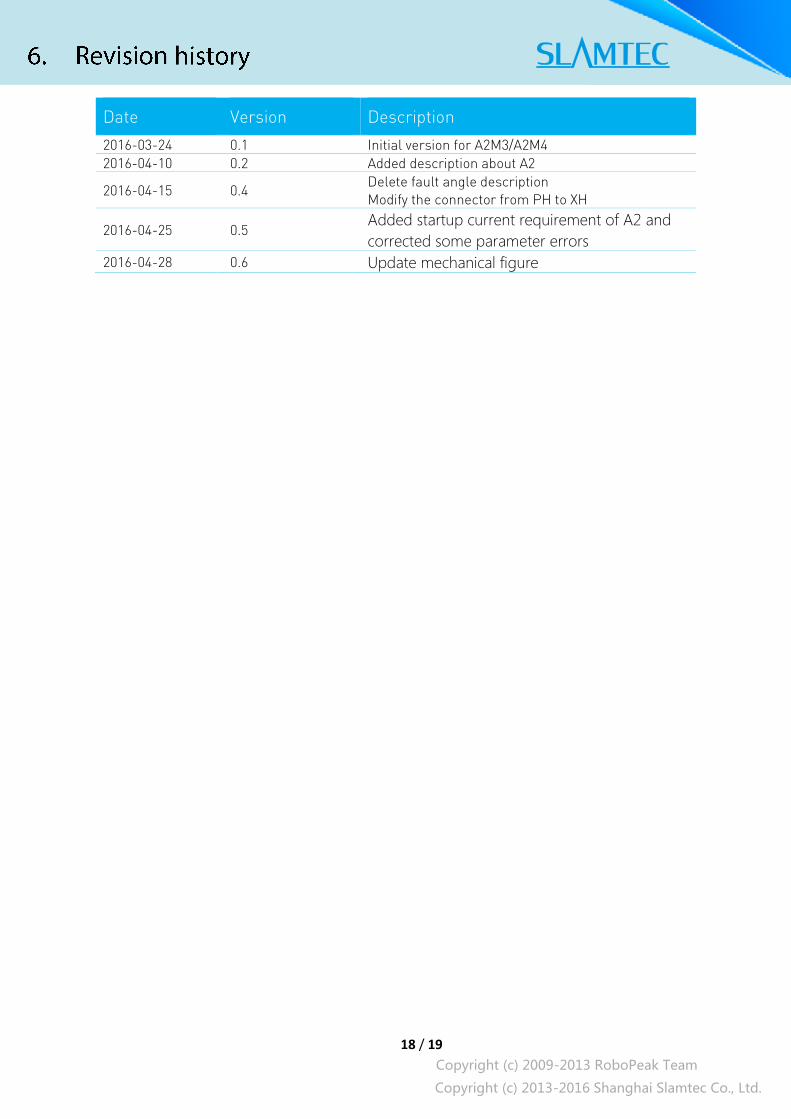
Date Version Description
2016-03-24 0.1 Initial version for A2M3/A2M4
2016-04-10 0.2 Added description about A2
2016-04-15 0.4 Delete fault angle description
Modify the connector from PH to XH
2016-04-25 0.5 Added startup current requirement of A2 and
corrected some parameter errors
2016-04-28 0.6 Update mechanical figure

19 / 19
Copyright (c) 2009-2013 RoboPeak Team
Copyright (c) 2013-2016 Shanghai Slamtec Co., Ltd.
Image and Table Index
FIGURE 1-1 RPLIDAR SYSTEM COMPOSITION ..................................................................................................... 4
FIGURE 1-2 THE RPLIDAR WORKING SCHEMATIC ............................................................................................... 5
FIGURE 1-3 THE OBTAINED ENVIRONMENT MAP FROM RPLIDAR SCANNING ................................................... 6
FIGURE 1-4 THE RPLIDAR SAMPLE POINT DATA INFORMATION ........................................................................ 7
FIGURE 1-5 THE RPLIDAR SAMPLE POINT DATA FRAMES ................................................................................... 7
FIGURE 2-1 RPLIDAR PERFORMANCE .................................................................................................................. 9
FIGURE 2-2 THE TREND GRAPH OF RPLIDAR RESOLUTION ................................................................................. 9
FIGURE 2-3 RPLIDAR OPTICAL SPECIFICATION .................................................................................................. 10
FIGURE 2-4 RPLIDAR OPTICAL WINDOW .......................................................................................................... 10
FIGURE 2-5 RPLIDAR SCANNING DATA COORDINATE SYSTEM DEFINITION ..................................................... 11
FIGURE 2-6 RPLIDAR POWER INTERFACE DEFINITION ....................................................................................... 12
FIGURE 2-7 RPLIDAR EXTERNAL INTERFACE SIGNAL DEFINITION ..................................................................... 12
FIGURE 2-8 RPLIDAR POWER SUPPLY SPECIFICATION ....................................................................................... 13
FIGURE 2-9 RPLIDAR SERIAL PORT INTERFACE SPECIFICATIONS ....................................................................... 13
FIGURE 2-10 RPLIDA SPECIFICATION FOR PWM SIGNAL OF MOTOCTL ........................................................ 14
FIGURE 2-11 RPLIDAR MISC SPECIFICATION ................................................................................................... 14
FIGURE 4-1 THE DEBUGGING GUI OF RPLIDAR ................................................................................................. 16
FIGURE 5-1 RPLIDAR MECHANICAL DIMENSIONS............................................................................................. 17