Embed Size (px)
Citation preview

Final Report
Shampoo/Conditioner Identification Device & Backpack Lever Arm System
By: Lu Ma
Nahum Kryzman Raj Shah
Team No. 4
Client Contact: Shampoo/Conditioner Identification Device Brooke Hallowell, Ph.D., CCC-SLP, F-ASHA
Associate Dean, Research and Sponsored Programs Director, School of Hearing, Speech and Language Sciences
College of Health and Human Services Grover Center
Ohio University Athens, OH 45701
(740) 593-1356 [email protected]
Backpack Lever Arm System
Gregg McClement [email protected]
Laura McClement [email protected]

2
Table of Contents
Section Page Number Shampoo/Conditioner Identification Device ABSTRACT …………………………………………………………………2 1. INTRODUCTION………………………………………………………..2-6 1.1 Background 1.2 Purpose of the Project 1.3 Previous Work done by Others 2. PROJECT DESIGN 2.1.1 Design 1………………………………………………………………..7-12 2.1.2 Design 2………………………………………………………………..12-18 2.1.3 Design 3………………………………………………………………..18-26 2.2 Optimal Design………………………………………………………….26-41 3. REALISTIC CONSTRAINTS…………………………………………….41-42 4. SAFTETY ISSUES………………………………………………………….42 5. IMPACT OF ENGINEERING SOLUTIONS…………………………….43 6. LIFE-LONG LEARNING…………………………………………………..44 7. BUDGET AND TIMELINE……………………………………………….. 45 - 47 8. TEAM MEMBERS CONTRIBUTION TO PROJECT……………………. 47 9. CONCLUSION………………………………………………………………47 10. REFERENCES………………………………………………………………48 11. ACKNOWLEDGEMENTS………………………………………………..48

3
Shampoo/ Conditioner Identification Device Abstract
This NSF-sponsored project is being carried out by students of the University of Connecticut Biomedical Engineering program, to aid an elderly client, who faces reduced visual perception, and substantial memory loss. The client is unable to differentiate between products within the household, and wishes to maintain her independence by using a device that will help make this distinction. Specifically, the team is working to design an assistive device to help in identifying shampoo and conditioner bottles in the shower.
On the basis of client’s requirements and an analysis of engineering
design (taking into account factors such as optimal efficiency, practicality, safety, comfort, and cost), the team has come up with a design which will output an audible message in response to the depression of a button (mechanical stimulus by the client).
Fundamentally, the device is a ‘talking’ belt, customizable to different size bottles. It consists of a voice-recorder player, which plays a pre-recorded message (outputted through a small attached speaker) when activated. Several buttons, located around the circumference of the bottle serve as these activation points. The physical characteristics of the device have been determined on the basis of surroundings in which the device will be most frequently operated, the shower. The design is unique, as it is rare to find a device that uses client’s input to identify the object that he or she is holding. This is due to the combination of decreased eyesight and memory loss which made elementary solutions to this problem ineffective. Thus, a more sophisticated and technologically advanced design was requested to aid the client. 1 Introduction 1.1 Background
An innovative biomedical appliance is required to aid Mrs. Smith, an
elderly woman with reduced visual acuity. In addition, Mrs. Smith faces mild-to-moderate progressive cognitive impairment. Despite these conditions, Mrs. Smith strives to remain independent and carry out her daily routine. One such task is the recognition of shampoo and conditioner bottles in the shower.

4
Her family has requested a lightweight waterproof shock-proof device that utilizes her auditory abilities. Several elementary alternatives have been attempted to resolve this issue, such as clearly segregating bottles with large letters and using containers of different dimensions, but have unfortunately failed. It is apparent that Mrs. Smith will require another means of discerning between the bottles, thus eliminating the need to deal with shapes, colors, and sizes.
The product should be able to connect to each bottle. When squeezed
gently, it should emanate an auditory voice signal - “shampoo” or “conditioner!” After an initial assessment of Mrs. Smith’s needs and environment in which the design is bound to operate, it is vital to account for safety (e.g. shock-resistant, corrosion-resistant). In addition, the device should be user-friendly and simple to operate. 1.2 Purpose of the Project
The purpose of this project is to design and develop an instrument that will allow Mrs. Smith to accurately differentiate between shampoo and conditioner bottles while in the shower. Due to conditions that result in reduced memory and vision, simple indicators to distinguish between these two objects have failed Mrs. Smith to reliably make a distinction between shampoo and conditioner bottles while in the shower. Other options have failed for Mrs. Smith because the effectiveness of those solutions relied on her memory and vision. Mrs. Smith requires a touch-sensitive device, which upon triggering will cause a sound signal to be produced.
1.3 Previous Work Done by Others
Several previous NSF projects are similar to the Shampoo and Conditioner Identification Device because they share the same goal of using voice outputs to aid people who are visually impaired.
Cynthia Henderson from the Department of Agricultural and Biological Engineering of Mississippi State University designed a voice output device for scientific calculators. The device sends user inputs from a calculator to a BASIC Stamp II microprocessor. The microprocessor then sorts and transfers the data to an ISD1000A voice chip that plays the information corresponding to the mathematical expression. This device is extremely helpful for people who need verbal reinforcement for visual stimuli.

5
Kurt Peterson and Neil Peterson of the Department of Electrical Engineering of North Dakota State University created a GPS voice output device for visually impaired cane users. This mechanism uses a GPS receiver and a PIC16F876 microcontroller to collect position, speed, and heading information every 1 to 5 seconds. These data are then processed by the V8600A Speech Synthesizer to generate voice outputs when users press on the keypad.
Verbal indication devices are also used in many children interactive learning toys. When user presses on the items, appropriate voice outputs help them to identify the objects, colors, shapes and learn phrases.
Figure 1. Fisher Price - Laugh & Learn Learning Table 1
Figure 2. Fisher Price - Jumbo Talking Elmo 1 Touch sensitive device with voice feedback are also used for training animals. When pets step on them, a sound signal emits out from the small speakers that are integrated in the device.
Figure 3. High Tech Pet - Radio Mat, Electronic Scat 2

6
1.3.1 Patent Search Results U.S. Patent No. 6,449,887 – Water Globe with Touch Sensitive Activation This device is a crystal ball system consisting of a support base and a display. The touch sensitive mechanism inside of the globe assembly drives the audio producing mechanism which produces voice outputs upon contact. 3 U.S. Patent No. 4,748,756 –Touch Activated Enhanced Picture Frame The picture frame contains a sound generating device that emits voice when user touches the touch sensitive contact area. The concept behind this device is the touch sensed by control circuitry which responds by activating and controlling the functioning of the built-in speakers. 3 U.S. Patent No. 7,264,377 - Sensor-Activated Audible Story Lamp A microcontroller is built into the lamp, which is connected to the touch sensor. Upon contact the microcontroller initiates communication of audible messages. 3 U.S. Patent No. 7,269,484 - Vehicular touch switches with adaptive tactile and audible feedback A manual control system for a vehicle includes a touch sensitive input element and an audible feedback generator. When user touches the device, a sound signal is generated and emitted. 3
1.4 Map for the rest of the report This report provides a detailed description of the device. Three alternative designs are summarized in the Project Design section. The team learned from these designs, and decided to modify and combine the best of each alternative designs to finalize the optimal design.
The optimal design section followed discusses every component of the device in great detail, along with the technical analysis of each part and the integrated circuits. Diagrams and figures are also given in this section to demonstrate the device from different angels of views.
The optimal design was not selected only based on the specifications, but
also on the realistic constrains such as economic, environmental, social, political, ethical, health, safety, manufacturability and sustainability as well as safety issues.

7
Since this project is founded for the National Science Foundation, there is a $750 allocated budget. The detailed budget for the project is listed near the end of the report. Planning is the key to completing any projects, therefore a timeline for the rest of the year is also included. The impact of engineering solutions and the life-long lessons that the team learned was discuss to conclude the report. 2 Project Design 2.1 Design Alternatives 2.1.1 Design 1 Objective
The client’s specific symptoms have resulted in the inability to make certain distinctions, and have led to an increased dependency on others. Mrs. Smith desires to be more self-reliant in terms of being able to differentiate between shampoo and conditioner bottles in the shower. As with this design and with all others that will follow, the objective is for a mechanical stimulus from the client to result in an auditory output, indicating which hair product is currently being used.
The first alternative design is capable of attaching to each individual
bottle, and is therefore customizable to a variety of sizes. When stimulation points (soft-touch buttons) are squeezed gently, emanation of an auditory voice signal - “shampoo” or “conditioner!” will occur. The fundamental concept of this device is the translation of a mechanical stimulus into a sound output. Essentially, there is reliance on the fact that the client will be able to depress one of six buttons in parallel. Here, each button represents a single-pole, single throw (SPST) switch in the circuit. Pressing any one or more of the six buttons will close result in a short, and complete the circuit.
This design is different from other alternative designs, in that it does not
require an external base. In fact, this is exactly what the client had asked for – the reliance on a mechanical stimulus (squeezing the bottle) for a voice output. The reason that an adjunct base was explored in other designs was that the team felt the device would become too bulky/heavy, making it difficult for the client to handle it. This type of device has its advantages, but has been carefully eliminated in the optimal design due to its unnecessary complexity, high expenditure, and unfeasibility to place a base in a small shower environment.

8
In the present design, a small speaker has been incorporated onto the belt. Soft insulation (Teflon tape) will be used to cover any wires to avoid any exposure of visibility from the outside. Furthermore, this will be covered in a nylon casing for its waterproof properties. By placing a small speaker on the belt of the device, there is no need for an additional output system, which may be expensive, inconvenient, and more space –inefficient.
Figure 4. Flow Chart for device operation The idea was for a 6 parallel push-button switches in parallel to function
as stimulation points for the system. These switches would be connected to a 6 volt battery source that would run the entire system. Initially, the team had planned for a voltage dividing system to accurately output 5 volts. This system was to be composed of a 10 ohm resistor in series with a 50 ohm resistor. However, after taking feedback from the adviser, as well as further analysis of the design, the team realized that this was not acceptable as a power supply for a microprocessor. Instead, a voltage regulator would prove optimal, due to its ability to automatically maintain a constant voltage level. This mechanism would protect electrical components from any irregularities in voltage or current, and clearly enhance the efficiency of the device. This modification has been taken into account, and incorporated in the final design, which will be discussed later in the report.
In this design, when any one of 6 buttons is pushed, the input signal is
initiated and the microcontroller sends a signal to the synthesizer. This would allow the output of a vocal prompt. The positions of stimulation points were designed to be most ergonomic, as a button would be present every 60 degrees around the belt. In this manner, it would be easy for the client to activate the device at her convenience. The advantage of using push buttons is that they only activate on a push sequence and will not continue to be run if they are not released.
9
Subunits Microcontroller
In order to have the sound output the group planned to use two different
chips. One of the chips was the microcontroller and the other will be used to output a particular voice prompt. The microcontroller is a BASIC Stamp II made by Parallax. The voice prompt controller is a V8600A Speech Synthesizer by RC Systems. The output from the V8600A chip was to be sent through an amplifier and finally out to a speaker. This setup is shown in the figure below.
Figure 5. The flow chart for operation of the chips
The BASIC Stamp II is a 24-pin DIP module that is used as an elementary microcontroller in most application. Its voltage requirements also fit the project parameters, as its range is 5 to 15 volts. The chip is designed to control an array of electronic devices including relays, sensors, motors, etc. The programming of this chip is done using the PBASIC language, which requires no compiler to be implemented. When the switches are activated the microcontroller will output an English ASCII text string to the Speech Synthesizer [2].
Figure 6. BASIC Stamp II
10
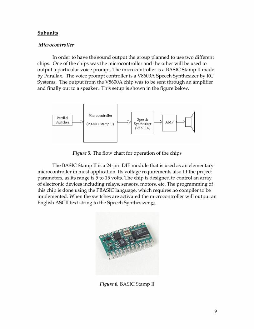
The V8600A Speech synthesizer is a compact speech synthesizer, and only uses 5 volts. The V8600A is designed to be piggy-backed onto a host PCB, such as a microcontroller. An eight-bit bidirectional data bus and read/write control pins enable the V8600A allow for easy manipulation of the chips parameters via the microcontroller. The voice output is controlled through software. The speed and pitch can be dynamically controlled by embedding the parameters in the text input. The volume will be controlled by using a 10kΩ potentiometer connected between the line pin and ground. Adjusting the potentiometer clockwise will increase the volume and counterclockwise will decrease the volume [3]. The speech synthesizer will output a signal, which can be amplified to increase the volume if necessary. However, the speaker incorporated in this design is compatible with iPods, and will provide a sufficiently loud auditory output that can be heard over the noise of a running shower.
Figure 7. V8600A Speech Synthesizer
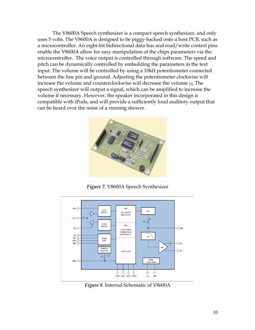
Figure 8. Internal Schematic of V8600A

11
The microcontroller and speech have the same voltage requirements. The main advantage of not controlling the voice prompt by the microcontroller is that it has less potential of complications. The memory on the microcontroller only needs to have one object stored, the ASCII text for “shampoo” or “conditioner.” The rest of the system is controlled by the speech synthesizer. This is far superior because the V8600A is a dedicated to only one task, voice out put. So any manipulation of the output can be controlled through this device by embedding commands through the input text.
Although this design would work technically, the team realized the size of
the speech synthesizer had not been accounted for (4.25’’ x 2.7’’). It was concluded that such a circuit would be difficult to incorporate onto a belt due to sheer size. In the optimal design, the team is using a different approach to an auditory output, which involves a smaller circuit. However, it still cannot fit inside the hose. Therefore, it will be accommodated onto the belt using a plastic encasing and appropriate insulation that is described in detail later in the report. Although the issue of the circuit board being inflexible is a valid concern, the optimal design’s circuit is merely 1.64 inches2, and will not make the device hard to handle.
Belt
Materials for the belt have been chosen based on the environment in which the design plans to operate. Given the properties of water and proximity to electrical parts, all measures should be taken to ensure that any possibility of contact is eliminated. This will be carried out through a waterproof casing to maintain client’s safety. In addition to making the device shock-proof, corrosion resistance is absolutely necessary for daily use and long-term product life.
Use of an appropriate material to use in the manufacturing of this device
would be similar to that of a hose, and has been also incorporated in the optimal design. The ‘Gilmour 4-Ply Medium Reinforced Rubber/Vinyl Bulk Hose’ is only 5/8 inches in diameter, increasing the total diameter of the shampoo bottle 1.25 inches. This is a manageable width, and will not make the device too bulky. In terms of material properties, the hose is made of rubber, and soft PVC. The high strength of the hose will ensure that the electrical components inside are protected. In addition, since hoses cater to water running at high speeds, the type of environment subject to the hose-made belt will cause negligible weathering.
Six holes can be made along the line of the hose and evenly spaced to incorporate the buttons. The buttons will be covered by an additional insulating (hot glue) layer from the inside to ensure that no water leaks into the inner

12
circuitry, located within the hose (belt). An additional hole will be made for the small speaker output, from which the client will receive an auditory signal.
To be able to customize the belt to various bottle sizes, the group will
create a watch belt mechanism. Here the hose (belt) will extend, as if it were a strap. The strap will have additional small holes and a buckle (the same concept as a watch belt) to change the bottle – diameter on which the belt can fit. Speakers
The speakers that will be attached to the Shampoo/Conditioner bottles need to be small and light to eliminate burden during the operation of the device. The IPod NANO portable mini speakers seem to be very suitable for this project because of their petite size and low voltage requirements.
They have a dimension of 8cm in length, 5cm in height, 2.4cm in width,
and a light mass of 38 grams. Since to minimize the total amount of weight of the device is one of the main goals of this project, the power source for the speakers becomes very important. These speakers only require two small AAA batteries.
Although these speakers are ideal in terms of being small in size and
requiring a low voltage for operation, iPod speakers are very specialized in terms of the type of devices they can be connected to. Therefore, in the optimal design, the team is using a general 8 Ohm speaker, that can be connected to output of the voice player circuit. The team has made sure to keep features such as the convenient spatial dimensions and low power requirement. These are described in detail later in the report. 2.1.2 Design 2 Objective
This alternative design is very different from the other two alternative designs as well as the original design in that it incorporates ideas that were brought to the team’s attention during the first round of senior design presentations. Instead of designing a product that uses a mechanical stimulus from the client (for purposes of item identification), a device that dispenses the product upon voice – activation may prove to be more convenient. This design would involve one terminal, which would be consist of the voice-recognition port, as well as separated containers that could be filled with the shampoo/conditioner of choice. The dispenser would be located at the bottom of

13
the terminal, releasing the product based on a voice signal (auditory command) from the client.
The product would eliminate the need for the client to physically carry
any object in her hand. This is a major advantage, as reduced visual acuity may be a hazard, when trying to grip and carry a heavy shampoo/conditioner bottle. It is clear that the safety advantages that this design provides surpass those of any other design. A mere voice signal by the client would result in the product being dispensed from a spout at the bottom of the terminal. In designing this device, it would be imperative to account for the fact that noise of the shower would exist in the background, and should not prevent the voice-signal from being recognized. In addition, vacant space of certain dimensions would have to be present in order to accommodate this device.
The benefit of using this alternative is added convenience to the client. In
comparison to the other designs, there is no need to customize already available touch-pads to fit the size of a belt that will wrap around a bottle. The initial designs assume that Mrs. Smith will be able to lift a full shampoo bottle (to which the device is attached). Although this is what the client has asked for, it does not seem to be the most effective and user-friendly design. This has led the group to think of alternative methods by which the product can reach the hands of the client, without needing high visual perception or complex cognitive skills.
However, after careful consideration, the team came to the conclusion that
this design is not suitable for the special environment that the device will be operated in – shower. Since the entire device is controlled by a single user voice command, the accuracy of voice recognition is vital, and the amount of the background noises in a shower will interference with the user command and cause potential problems. Therefore, the team decided that this design is not optimal.
Figure 9. Flow Chart for device operation
14
Shampoo Conditioner
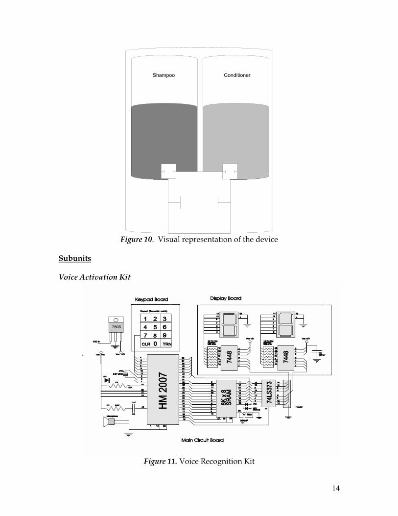
Figure 10. Visual representation of the device
Subunits Voice Activation Kit
Figure 11. Voice Recognition Kit

15
This circuit planned for use will have three components the main circuit board, the display board, and the keypad board. The only component that will actually be implemented into the final design is the main circuit board. The other two pieces will only be used during the programming phase. The board will work as follows. The power delivery for this kit will provided for a 9V battery routed through a voltage regulator. The voltage regulator used will be a 7805 chip. This chip is ideal because it has a max voltage rating of 5.25 volts and a typical voltage of 5 volts. The current out of the voltage regulator is also set at 500mA. The chip is small and quit cheep to buy. A block diagram describing the voltage regulator is given bellow.
Figure 12. Voltage Regulator
The brain of the circuit is the HM2007 chip. This is the main voice recognition switch. The other component that is vital for the system is the 8K-byte SRAM chip. The HM2007 has to operating modes manual and CPU controlled. This project is interested in only the manual mode. In this mode the key pad is used to control the state of the HM2007 chip. When power is first applied to the chip it initializes. If the WAIT pin is low then the chip will run through its memory check in order to check the state of the 8K SRAM. If the WAIT pin is high it will skip the memory check process and go into the recognition mode. When WAIT is high and RDY is low the chip is ready to read voice inputs to be recognized. Once an input is given the RDY will become high the chip will run through the recognition process. After this step is complete the result appears in the D-bus with the pin DEN activated. Figure 4 describes how the data is transferred through the data bus. A is the binary code range 0 to 4 and B is in the range 0 to 9. When training the chip the first step is to use the key pad to select the word number. The number is inputted by entering the digits on the keypad one

16
at a time. When the numbers are pressed on the key pad they same number is sent down the D-bus. After the word number is entered the function key is used to choose the operating function. If CLR is pressed the corresponding word pattern is cleared from the SRAM and the HM2007 goes back to recognition mode. If the TRN function is activated the training process will be initialized. When the WAIT pin is high the chip will send a low signal to the RDY pin, which means the chip is ready to accept a voice input. Once the voice input is completed the RDY pin goes low indicating that it is ready to go through the recognition process.
Figure 13. D-bus transfer code
Figure 14. Voice Recognition Chip
Microphone
After exploring available products in the market, the team decided the
Mini Microphone (Model Number: HX-0018-1) manufactured by Wellsun Industry (Shenzhen) Co.,Ltd is very suitable for shampoo/conditioner identification device. They are small in size and can rotate 180 to 360-degree, have a 50-60 Hz frequency response, and -39, +/- 3dB sensitivity. The microphone is compatible with almost all the sound equipment, and can be directly plugged into the voice recognition circuit in the shampoo/conditioner

17
identification device. Although the Mini Microphones are made of water-proof material, they will be covered by the insulating material just like the rest of the device to ensure the safety of the user [4].
Figure 15. For size comparison analysis [4]
Figure 16. Mini Microphone [4]

18
Outer Structure
The design for the outer structure of the voice-activated shampoo and conditioner will be based on a product called the ClearChoiceTM Dispenser, available through the ClearChoice Corporation. It consists of two separated compartments, which can hold different products. This produce will be modified so that when the client inputs a voice signal, she will place her hand below the spout and wait for the product to be dispensed. The product shown below has two spouts, the team wishes to have one dispenser, connected to two the separate compartments. Based on the voice command, one of the two valves will open, dispensing the product into the client’s hands.
Some features that make the ClearChoice Dispenser an appropriate
product to work with are that they come with wall brackets, and can fit into corners or flat walls. Each compartment holds approximately 15 oz, which is a substantial amount assuming that small amounts of shampoo/conditioner would be used every 2-3 days. In terms of the exact dimensions, the two-part reservoir system is 7.5 inches in height, 5.5 inches in width, and 3 .125 inches in depth. The voice activation circuitry will be attached to the device, and will increase the height of the total device by approximately 2 inches. The weight of the empty container is .42 kg, making it easy to attach/detach to the wall in case of occasional maintenance needs.
The ClearChoice Dispenser is made out of a material called ABS, or Acrylonitrile butadiene styrene. ABS combines the high strength and rigid nature of acrylonitrile and styrene polymers with the toughness of the polybutadiene rubber. In addition, ABS is resistant to various aqueous environments (acidic and basic), making it a durable material and viable choice for this product. [2]
Figure 17. Product for base of design

19
2.1.3 Design 3 Objective:
This alternative design plans to incorporate ideas that were brought to the team’s attention by comments and suggestions from alternative design reports. Previous designs have involved the attachment of accessory speakers onto a touch-sensitive belt, or a belt with several buttons along the circumference of the bottle. These serve as mechanical stimulation points, which the client must use to activate subsequent parts of the system and result in an auditory output. In the proposal as well as the first alternative design, small speakers were attached to the belt itself. Thus, the need for an additional station or base was eliminated. However, it quickly became clear to the group that such a device (which requires components such as a speech synthesizer, speakers, a battery, and other circuitry) would be difficult to produce in terms of being able to adhere to dimensional and weight requirements. Even if the device were light, the volumetric bulk would make the instrument impractical to use.
In alternative design two, the entire system was incorporated into one
unit. The shampoo/conditioner was dispensed based on voice-activation (rather than a mechanical stimulus). This product would eliminate the need for the client to physically carry any object in her hand. This was a major advantage, as reduced visual acuity, when trying to grip and carry a heavy shampoo/conditioner bottle carries an element of risk. However, the method of delivery in this case is different from what the client originally requested; the team is currently working with the client to find out whether this design would be suitable, given her health conditions.
In the event that the client insists on complying with the original request
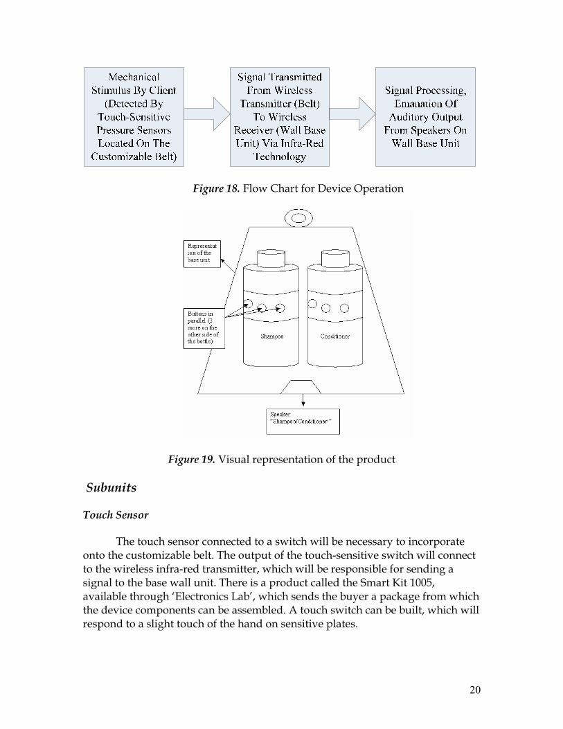
(mechanical stimuli), the team has decided to make changes to the customizable, belt-and-speaker based, auditory output design. Rather than encompassing all the desired components onto a single belt, the team has decided to have a separate wall unit, in which appropriate circuitry, speakers, and an infra-red wireless receiver can be placed. The belts will merely consist of a touch-sensitive pad and an infra-red wireless transmitter. Once a mechanical stimulus is detected by the touch-sensitive pressure sensors, a wireless signal will be sent (via infra-red technology) the wall unit. Upon receiving this, the speaker on this base will emit an auditory output, indicating the product that Mrs. Smith has in her hands.
20
Figure 18. Flow Chart for Device Operation
Figure 19. Visual representation of the product
Subunits
Touch Sensor
The touch sensor connected to a switch will be necessary to incorporate onto the customizable belt. The output of the touch-sensitive switch will connect to the wireless infra-red transmitter, which will be responsible for sending a signal to the base wall unit. There is a product called the Smart Kit 1005, available through ‘Electronics Lab’, which sends the buyer a package from which the device components can be assembled. A touch switch can be built, which will respond to a slight touch of the hand on sensitive plates.

21
Figure 20. A circuit diagram of the touch sensor. (Dimensions: 5.5 X 4.2 cm)
In terms of technical specifications, a supply voltage of 12 V (DC) is required. From the diagram shown below, it is clear that the circuit uses eight components. The main portion of the circuit is the IV CD 4011, which is connected as the ‘Flip-Flop’, as described by the company. Pins #9 and #13 of the IC are the ‘Set’ and ‘Reset’ contacts of the ‘Flip-Flop’. The IC is part of a category called CMOS or complementary metal-oxide-semiconductor, which requires a very low current into its gates for purposes of control. The touch operation is made possible due to the high sensitivity of the circuit. Two resistors, R1 and R3 connect two gates (which are held at logic state ‘1’) to the positive supply line. These resistors have high impedances of 10MΩ. If a set of contacts are touches, the skin resistances closes a circuit between the corresponding gate and a negative supply line. Skin resistances for small areas of the skin (fingertips) are usually much lower than 10MΩ; the gate is changed to logic condition ‘0’, which makes the ‘Flip-Flop’ change state. This change of state causes the circuit to alter its balances state, and toggle the switch. An output from the ‘Flip-Flop’ is connected to a relay through a transistor, which is finally connected to the switch. Circuit Components
R1 = 10MΩ 1/4 W D1 = Lead Red R2 = 10MΩ 1/4 W D2 = 1N4148 diode
R3 = 1KΩ 1/4 W
IC1 = CD4011 CMOS IC RL1 = 12V Relay Rated at 250 V / 2A

22
Main Voltage Regulator
The power delivery for this kit will provided by two 9V battery routed through a voltage regulator. The voltage regulator used will be a 7812 chip. This chip is ideal because it has a max voltage rating of 11.5 volts and a typical voltage of 12 volts. The current out of the voltage regulator is also set at 500mA. The chip is small and quit cheep to buy. A block diagram describing the voltage regulator is given bellow.
Figure 21. Voltage Regulator
Microcontroller
The microcontroller that is ideal for application to this project is the PIC18F1230.
This chip offers the ability to of customization and self programming based on the mode that it is put into. It also features pin break-out so that it is easy to use with a protoboard. There is also a built in potentiometer that is used to control a 10-bit analog-to-digital input channel. The microcontroller consists of two external clock modes and two external RC modes. However the two most pertinent aspects of this chip are the internal oscillator and the flash memory module. The microcontroller will only be used to accesses memory and output a specific voice prompt from the text to speech module.
Figure 22. Microcontroller Pin outs

23
Text to Speech
The V8600A Speech synthesizer is one of the most convenient and compact
speech synthesizers on the market. It is ideal for our application because it only uses 5 volts to power the entire chip. The V8600A is designed to be piggy-backed onto a host PCB, such as a microcontroller. An eight-bit bidirectional data bus and read/write control pins enable the V8600A allow for easy manipulation of the chips parameters via our microcontroller. The voice output is controlled through software. The speed and pitch can be dynamically controlled by embedding the parameters in the text input. The volume will be controlled by using a 10kΩ potentiometer connected between the line pin and ground. Adjusting the potentiometer clockwise will increase the volume and counterclockwise will decrease the volume.
Figure 23. Text to speech Synthesizer
The microcontroller and speech synthesizer should work well together because they both have the same voltage requirements. The main advantage of not controlling the voice prompt by the microcontroller is that it has less potential of complications. The memory on the microcontroller only needs to have one object stored, the ASCII text for “shampoo” or “conditioner.” The rest of the system is controlled by the speech synthesizer. This is far superior because the V8600A is a dedicated to only one task, voice output. So any manipulation of the output can be controlled through this device by embedding commands through the input text. Wireless Transmitter/Receiver The wireless receiver and transmitter devices should be relatively easy to build. A schematic of the general circuit is shown bellow. Vcc can be as low as 3 volts depending on the transistor that is used. The resistor tolerances for this device will also be quite large so there is no worry that the part will be expensive.

24
Figure 24. IR Transmitter/Receiver
The system works in this way. When the switch is closer around Vcc and GND there is an emission from the LED. The photo diode on the receiver end will then pick up the signal of a specific frequency and make a closed loop on the other end. The transistor will close and a voltage high will be sent to a specific pin-in on the microcontroller. The controller will then relay the signal to the synthesizer, which will output the proper voice prompt.
Belt
To be able to customize the belt to various bottle sizes, the group will use an adjustable belt, which will wrap around the entire bottle. The picture below shows the ‘Aquapac Waterproof Belt’. A thin, flexible rubber casing will cover the all circuitry (except the touch sensitive plates) and the wireless transmitter.
Figure 25. Belt

25
Outer Structure - Base
The base – wall unit will be modified from a product, available in the market by the Velleman Corporation It is simply a box, manufactured from a material called ABS, or Acrylonitrile butadiene styrene. This is a commonly used thermoplastic in the manufacturing of lightweight, rigid and customizable molding products. The advantage of using ABS is that it combines the high strength and rigid nature of acrylonitrile and styrene polymers with the toughness of the polybutadiene rubber. In addition, ABS is resistant to various aqueous environments (acidic and basic), making it a durable material and viable choice for this product. [2] .
Figure 26. Picture of the ABS casing, which will be used in making a ‘Base Unit’ for the Shampoo/Conditioner Identification System.
The dimensions of the ABS box are 160x95x55mm. Given the size of the speakers, voice synthesizer circuit, and wireless receiver, this amount of volumetric space should be sufficient to hold the necessary components. The weight of the container is approximately two pounds. This will increase with the components that will go inside of it. Wall brackets can be bought, so that the container can fit into corners or flat walls in a bathroom setting. Alternatively, it may be placed on the ground immediately outside of the shower.
One limitation of this design is that the base unit must be close (an
estimated 1 meter) to the wireless transmitter. It is vital that this condition is met, to ensure that the infra-red signal is optimally transmitted and received.

26
Speakers
The speakers that will be attached to the Shampoo/Conditioner bottles need to be small and light to minimize the device. The IPod NANO portable mini speakers seem to be very suitable for this project because of their petite size and low voltage requirements.
They have a dimension of 8cm in length, 5cm in height, 2.4cm in width,
and a light mass of 38 grams. Since to minimize the total amount of weight of the device is one of the main goals of this project, the power source for the speakers becomes very important. These speakers only require two small AAA batteries. The speaker will be connected to the output of the voice synthesis chip that is part of the base unit circuit because they are compatible with all audio output signals, and costs about $17 per piece. These great qualities are ideal for the Shampoo/Conditioner Identification device.
Figure 27. IPod NANO Portable Mini Speakers 2.2 Optimal Design 2.2.1 Objective
For individuals with physical and psychological limitations, creative healthcare products can be used to help them independently perform certain

27
tasks. The client’s specific symptoms have resulted in the inability to make certain distinctions, and have led to an increased dependency on others. Mrs. Smith desires to be more self-reliant in terms of being able to differentiate between shampoo and conditioner bottles in the shower. Even with mild cognitive impairment and reduced visual acuity, Mrs. Smith wishes to remain independent in carrying out her daily routine.
Similar to the initial design, the optimal design will be able to connect to
each bottle, customizable to a variety of sizes. When squeezed gently, it should emanate an auditory voice signal - “shampoo” or “conditioner!” Even though the fundamental concept of this device is the same as the previous design (translation of a mechanical stimulus into a sound output), the process through which is done involves a different electrical design. Here, instead of a touch-sensitive pad, there is reliance on the fact that the client will be able to depress one of six buttons in parallel. This is a very simple electrical design, in which each button is represented by a switch in the circuit. Pressing any one or more of the six buttons will close result in a short, and complete the circuit of the voice recording kit that is placed on the belt. This kit is capable of recording and playing back up to 40 seconds of message.
A small speaker will be incorporated into the belt. Soft insulation will be
used to cover any wires to avoid any exposure of visibility from the outside. Furthermore, this will be covered in a nylon casing for its waterproof properties. By placing small speakers on the belt of the device, there is no need for an additional output system, which may be expensive, inconvenient, and more space –inefficient.
The advantage of using this alternative is the simplicity of design. In
comparison to the initial design, there is no need to customize already available touch-pads to fit the size of a belt that will wrap around a bottle. Generally, the touch-sensitive pads available (‘scat mats’) are placed straight, on a horizontal surface. In the case of wrapping them around a shampoo/conditioner bottle, we would have to make sure that the strain induced by this type of placement would not trigger an output of the signal. With the current alternative design, we are making the assumption that Mrs. Smith will be capable of pressing any one of the six buttons on the belt of the bottle. We think that this possible, as the buttons will be of substantial size, light-weight, and clearly perceptible.

28
Figure 28. Flow Chart for device operation
ButtonsSpeaker
Figure 29. The front view of the finished device on the bottle

29
ButtonsSpeaker
Voice Recording
Kit
Figure 30. Back view of the product

30
2.2.2 Subunits 2.2.2.1 Main Voltage Regulator
The power delivery for this kit will provided by a 6V DC supply routed through a voltage regulator. The importance of a voltage regulator is that unlike using a direct voltage source, the voltage regulator does not allow for fluctuations in the voltage or current that it outputs. For most regulators this is done by comparing the output voltage to some internal fixed reference voltage. Any difference is routed through an amplification system and is used to control the regulation element. To further explain, when the output voltage drops, the regulation element is commanded to produce a higher voltage. For some regulators if the output voltage is too high, the regulator just stop taking current and depends on the current draw from whatever is being powered to pull the voltage down. In this way, the output voltage is held roughly constant.
The voltage regulator used will be a 7805 chip. This chip is ideal because it
has a max voltage rating of 5.2 and a typical voltage of 5 volts. This level of fluctuation is well within the tolerances for this design. This regulator also comes in two different designs so it will be easy to adapt to any lay out. The two types are pictured below. The current out of the voltage regulator is also set at 500mA. The chip is small and quit cheap to buy. A block diagram describing the voltage regulator is given below.
Figure 31. Two Chip layouts

31
Figure 32. Block Diagram
2.2.2.2 Microcontroller
The microcontroller that is ideal for application to this project is the ISD2540 because this is a recorder and playback chip in one. The CMOS devices include an on-chip oscillator, microphone preamplifier, automatic gain control, ant aliasing filter, smoothing filter, speaker amplifier, and high density multi-level storage array. In addition, the ISD2500 is microcontroller compatible, allowing complex messaging and addressing to be achieved. Recordings are stored in on-chip nonvolatile memory cells, providing zero-power message storage. This unique, single-chip solution is made possible through ISD's patented multilevel storage technology. Voice and audio signals are stored directly into memory in their natural form, providing high quality, solid-state voice reproduction
This microcontroller meets the needs of the project because of it size,
functionality, and power consumption. The chip is .5 inches wide, .3 inches long, .04 inches thick. This makes the unit ideal for the parameters of this project. The chip also function with a voltage range as low as 4.5 volts and up to 7.0 volts. This coupled with the 7805 voltage regulator will be a stable system because the fluctuation in voltage from the regulator is significantly smaller than what the chip can handle. The maximum current draw from any of the parts of this chip is 30mA. Given that the power supply planned for this device will be providing 500mA indicates that this device will have the ability to run on this battery for a significant amount of time before it needs to be recharged.

32
The sound quality delivered from this microcontroller is also quite important to this project. Since this device is planned for use in a shower where the running water will tend to distort and voice prompt care must be taken is choosing a controller with good sound output. The ISD2500 is available in 4.0, 5.3, 6.4, and 8.0 kHz sampling frequencies. Increasing the duration of the speech recording decreases the sampling frequency and bandwidth. This intern affects the sound quality because of the filter pass band. The sound volume from this device is typically adequate for application where outside distortions are not of much concern. However, for this project volume is of great importance. Another great advantage of this chip is the EEPROM memory storage. This first advantage is that the memory is integrated into the chip. This saves on bulk and creates a smaller chance of error than attaching a separate memory device. EEPROM is a full non-volatile memory and provides zero-power message storage. This means that even if the device has no power coming to it the message in the memory will still be saved. In fact the messages can be stored for up to 100 years with no power. This means that there is no need for a backup battery to ensure that the stored voice prompt is saved.
The volume can be adjusted through a trick method. The typical speaker
attached to this device is a small 4 or 8 ohm unit. This is also the type of sound output device that will be used in this project. Small speakers such as these are not efficient at reproducing low frequency sound. They therefore should only used to output high frequencies and there is no need to even run low frequency signals through them. Based on this if the low end frequency response is limited this should increase the volume of the high frequencies. The way to do this is to set different values for C4 & C6 in the diagram below. When these capacitors are set at 0.1uF, signals above 160Hz are not attenuated. By lowering the capacitors values by a factor of 10 to 0.01uF will increases this low end pole to 1500Hz. Another, less practical, option is to use an amplification stage.
Using an external amplifier however, may introduce other issues that are
less than desirable. An example would be that the level of noise distortion will be intolerable by our client. The other factor that needs to be considered is the added bulk and power consumption. That being said the differential output may be fed directly to an amplifier such as an LM386. If you use the amplifier between one output pin (either pin 14 or 15) and ground it is very important that the unused output pin not be grounded. It must be left unconnected.

33
Figure 33. Microcontroller Pin outs
The development of this chip will require a different circuit than the one
that will be used in the final assembled project design. This is because during nominal use the chip will only be set to playback mode. The only control that the client will use is the Start/Pause function which is executed through a series of pushbuttons connected to the CE pin. During development of the device the setup will look similar to the figure bellow. In this circuit design a message can be recorded to the device by setting the P/R pin to ground and pulsing the CE pin to ground. This will then initiate the record function. To end the recording phase the CE will be pulsed again. This places an EOM (End Of Message) marker in the memory internally. This is done so that during playback the device will automatically end the start phase at this marker and reset itself to play the message again. Once the message is satisfactorily stored the device can be set to playback mode permanently by tying the P/R pin to Vcc.
Figure 34. Picture of Microcontroller

34
Figure 35. Diagram of development circuit
For this specific application the record function will only be used during
the programming phase of the project development. When the device is going to be sent out to the client the chip will continually be set in the playback mode (i.e. P/R will be set to high). When the device is being programmed the P/R will be set low and since there is only one prompt that needs to be recorded the address line will be permanently tied to address 1. The record phase is started by pulling either CE or PD low. Once the message is recorded the record phase is ended by pulling the either CE or PD high. During normal operation the P/R input will be set high so that the controller is continually in playback mode. This way the series of buttons can just be attached to the CE or input in order to control when the prompt is played. During each playback the device will output a prompt until the EOM marker is reached. Once it is reached the device goes to the next message in the memory. However, since in this project the pointers will all be tied to ground the device will automatically reset to the message that is stored on it. 2.2.2.3 Belt
Taking into consideration the environment in which the device will operate, there are certain requirements that have guided us in choosing the appropriate materials for the belt. Given the properties of water and proximity to electrical parts, all measures should be taken to ensure that any possibility of contact is eliminated. This will be carried out through a waterproof casing to maintain client’s safety. In addition to making the device shock-proof, corrosion

35
resistance is absolutely necessary for daily use and long-term product life. In making sure that these requirements are met, there is a need to ensure that the weight of the entire device is still kept within a reasonable limit. A device that is light in weight would reduce risk of injury to the client, in-case the bottle/device falls.
Figure 36. Material for belt An appropriate material to use in the manufacturing of this device would
be similar to that of a hose. The ‘Roll a Hose’ Flat Hose is only 12mm in diameter, increasing the total diameter of the shampoo bottle 2.4 cm. This is a manageable width, and will not make the device too bulky. In the optimal design, the belt of this diameter will only include small touch buttons. Therefore, the hose’s width will be sufficient.
The small circuit will be placed into a waterproof, plastic container.
Outgoing wires, connecting the buttons and the speaker to the circuit will run through the belt, which will be properly insulated to prevent any contact with water.

36
Figure 37. Diagram of the circuit, encased in a small plastic rectangular box.
In terms of material properties, the hose is made of rubber, and soft PVC.
In addition, it is covered with a layer of nylon and cotton. This satisfies the requirement of making the belt resistant to water, and corrosion. The high strength of the hose will ensure that the electrical components inside are protected. In addition, since hoses cater to water running at high speeds, the type of environment subject to the hose-made belt will cause negligible weathering.
Six holes can be made along the line of the hose and evenly spaced to incorporate the buttons. The buttons will be covered by an additional insulating layer from the inside to ensure that no water leaks into the inner circuitry, located within the hose (belt). An additional hole will be made for the small speaker output, from which the client will receive an auditory signal.
To be able to customize the belt to various bottle sizes, the group will
create a watch belt type of mechanism. Here the hose (belt) will extend, as if it were a strap. The strap will have additional small holes and a buckle (the same concept as a watch belt) to change the bottle – diameter on which the belt can fit.

37
Figure 38. Belt Mechanism
Buttons
SpeakerBelt
Voice Recorder
Player Circuit
Figure 39. Belt assembly

38
2.2.2.4 Pushbutton Switch
The 6 buttons on the belt will essentially be ‘normally –open, soft-touch momentary switches’. These push buttons are small, with dimensions that allow them to fit into a circular hole that is 9.5 mm in diameter. Therefore, since the diameter of the hose is 12mm, it is clear that the buttons will fit and still leave space to accommodate the circuit wires. In terms of insulating the buttons, the team has planned to use hot glue to fill any space in between. This will allow the formation of a water tight area, eliminating the possibility of an electrical short.
Figure 40. Small, normally-open soft-touch momentary switch
The soft-touch momentary switch is an example of an SPST (single pole, single throw). This is a simple on/off switch. Here, the two terminals are either connected or not connected to anything.
The activation of the system will work through pushbutton switches that will surround each bottle. There will be 6 buttons that are connected in parallel across the battery source. When any of the 6 buttons are pushed the input signal is initiated. The design should be quite effective because it will allow for a button every 60 degrees around a bottle of shampoo or conditioner. In this way it will be easy for our client to activate the device at her convenience. The advantage of using push buttons is that they only activate on the push sequence and they will not continue to be activated if they are not released. 2.2.2.5 Speakers
The speakers that will be attached to the Shampoo/Conditioner bottles need to be small and light to minimize the device. In addition, the output from the message recording circuit drives a 4 ohm or an 8 ohm speaker. Taken all these into consideration, the team has decided to use the 4 ohm 8 watts speakers from skycraftsurplus.
They have a dimension of 3 and 5/16’’ in diameter which is small enough
to be place on a shampoo or conditioner bottle. Since the device will be operated in the shower, the speakers also need to be loud enough to produce a voice output that is still clear with all the background noises. These speakers generate

39
minimum 8 watts up to 15 watts, and they only require up to 4 volts of power. The speaker will be connected to the output of the message recording circuit because they are compatible with all audio output signals, and costs about $1.50 per piece.
Figure 41. 4 ohm speakers (sk2052) 2.2.2.6 Batteries
The voice recorder/playback circuit, which further drives an 8 Ohm speaker, is powered by a 6V DC supply. This will be provided by a battery pack, also attached to the external part of the belt. The team has decided to use the Powersonic PS-605 F1 6V 0.5ah as the source. Specifically, it is small in size and lightweight. Its capacity is 500mAh, and supplies 6 V. Its dimensions are 2.24’’ x .55’’ x 1.97’’. Its weight is merely .25 lb, making it easy for the client to carry.
Figure 42. Battery pack

40
3 Realistic Constraints
Engineering Standards must be taken into consideration when designing and developing new products. Some of organizations that specializing in creating and monitoring engineering standards include American National Standards Institute (ANSI), American Society for Quality (ASQ), Association for Advancement of Medical Instrumentation (AAMI), International Organization of Standardization (ISO), and National Institute of Standards and Technology (NIST). The Shampoo/Conditioner Identification device must meet or exceed the engineering standards and guidelines provided by the standard organizations because not only do they ensure the safety of the users, but they also enhance the quality of the product. Several standards that are relevant to this project specifically are EN 1441:1997 Medical Devices (Risk Analysis), and EN 868-1:1997 (standardized packaging). i
In terms of economic constraints, the primary limitation is the allotted budget of $750. The device designed should be as affordable as possible, as it may hold potential to serving a larger population of senior citizens at some point. Families that require this device will vary in income levels. The solution will satisfy this fundamental condition.
The shampoo and conditioner identification device is essentially an
adaptation of a touch sensitive device that generates a voice output through a speaker that is placed on a separate unit. Striving for the highest quality; the device will be designed and assembled in manner with which it is economical to produce.
With reference to the environment, all measures will be taken to ensure
that the device causes negligible or no harm to the surroundings. Specifically, this involves adequate disposal of batteries, and the waterproof nature of this system (to avoid leakage of toxic substances from the battery into the surrounding). Construction materials of the device will account for the client’s health and safety.
In terms of sustainability, the device will have to be capable of
withstanding a variety of temperatures and a moist environment, which it will be constantly exposed to. Selection of appropriate materials for this device will be essential for corrosion resistant properties. In case of unintentional damage, the device must have accessible electrical test points for checking or repairing its operation.

41
Considering the properties of this device and its application, its
manufacturing will involve a detailed consideration of each component. The safety measures will be central to the manufacturing decisions. Other factors will be based upon ergonomics and client convenience. It is expected that the circuitry and design to be relatively easy to replicate, in case a larger market opens up for this type of product.
In addition to using insulating and airtight material in a wet surrounding
(to make the device shock-proof), low-voltage power sources are used to make sure that all electrical components work according to the simulated model, we will ensure that the working life will be optimized. Materials with rough edges or sharp protrusions will not be incorporated to abide by the underlying values, which is to guarantee the safety of the client.
There is one social constraint, which is that the device might need to be
removed and attached to other shampoo and conditioner bottles. This will require someone to periodically visit Mrs. Smith and do the needful. Therefore, a minute element of dependency on another individual still exists.
4 Safety Issues
The main safety concerns of the Shampoo/Conditioner Identification device are due to the unusual environment that it will be operated in – shower. The device includes electrical circuits which contain parts that will cause shock when exposed to water, therefore the entire device will be enclosed with insulating material to prevent water from entering. The security of the attachment of the device is another critical safety constraint because it will be placed on a relatively wet and slippery surface.
The shower has limited space, hence it is likely that the user could
accidently run into the device. The device should have as few sharp edges as possible to avoid potential harm. Minimize the size of the device also increases the available space to the user in the shower, thus the device need to be very compact. The device has a lot of electrical components, so the reliability of these parts will be very important. The batteries which act as the power source of the entire device will need to be small yet powerful enough to prevent operational failure, which consequently may result in inconvenience or even injuries to the user.

42
5 Impact of Engineering Solutions
It is clear that engineering solutions impact humanity at multiple levels, and can be seen in almost any activity carried out on a daily basis. Engineering has the potential to transform the way in which humans live their lives, and also advance knowledge and practices in a manner that is unimaginable
Based on an optimal design for the shampoo/conditioner identification device, it is obvious that a significant impact can be made at a global level, for clients with cognitive impairment, or reduced visual acuity. Memory loss is a major symptom of patients with Alzheimer’s disease, a health condition that is most common in individuals above the age of 65. At present, more than 5 million Americans are estimated to have Alzheimer’s disease. By the middle of the century, it is estimated that 14.3 million Americans will have the disease. Therefore, it is clear that a large market for this kind of device will develop over the course of the next few decades. This product can be used for patients with low visual acuity, which may be caused by a disorder, or during healing time after ophthalmic surgical procedures. Patients (especially those that are single) may need temporary assistance in recognition of items within their household. Thus, a device such as the shampoo/conditioner identifier will provide assistance in doing so. The current project is catered to the identification of specific bottles of hair products for use in the shower. However, it is possible to diversify applications using the same concept. A recognition device can be used in the kitchen for beverage bottles or food containers. When discussing engineering solutions in an economic context, it is natural to analyze the market and customer base. Generally, a conservative estimate is taken, in which it is projected that 10% of the customer base will be using the product within five years of release. However, this may change depending on company strategy and the method of marketing used. There would be two customer bases, one that would need this device permanently (individuals with Alzheimer’s disease), and post-ophthalmic surgery patients, that would require it temporarily. Thus, it may be beneficial for a company that was responsible for manufacturing and selling this product to have two separate marketing and sales strategies. In the first case, the product would be sale. In the second case, the product would be rented out to the consumer. Depending on factors such as total costs, and the profit margins desired, a price for both schemes could be determined.
However, it is vital to evaluate whether this type of product would be successful in a global scale (by analyzing cultural norms). In developing

43
countries, it would be hard to imagine this sort of device being successful. In many developing countries, it is customary to see elderly parents living under the same roof as their son and his family. It is also common to see domestic help around families that are middle to upper class. Therefore, even if this device was made affordable, the group feels that cultural norms would prevent it from being a financially lucrative product to produce in this type of market.
In an environmental context, engineering solutions such as this do not
seem to pose much of a threat. In terms of manufacturing a device such as the shampoo/conditioner identification device for a market of this size, the amount of pollution caused to the environment (land, air, water) is negligible in comparison to production of other products, in which harmful fumes or toxic wastes may be emitted. An optimal design plans to use a small dc power source (battery). Inadequate disposal of the batteries is the only other cause of concern to the environment. However, it is unlikely that this problem will be significant enough to threaten natural surroundings in any way.
6 Life-Long Learning
For this project, the majority of what the team has learned involved comments on previous alternative design reports and other peoples’ experiences in designing the same device. In spring 2007, one senior design group created a shampoo/conditioner identification device for the same client. However, their design did not meet the specifications of the client, and unfortunately, could not be utilized. Through comments from the adviser, reviews from the client, and research, the group have learned about what constitutes an excellent design and what sort of features can lead to problems.
Last year, although the previous design group incorporated a clever idea,
it did not meet the expectations of the client. The instrument functioned in a manner that involved lifting the bottle off of a base, which then output an auditory signal. This was not what the client had asked for, since Mrs. Smith wanted to rely on a mechanical stimulus (squeezing the bottle) rather than having an adjunct base, for which she would need to find a vacant space in the shower. In addition, the device attached to the shampoo/conditioner bottle in order to make this work exceeded the weight limit, in terms of what was reasonable for the client to handle.
Primarily based on a critique of last year’s product from an engineer, the
team has decided to eliminate having multiple components on the belt material, which would potentially increase volume and weight, beyond what is acceptable for the client. However, after analysis of the client’s health conditions, the team

44
feels that a base terminal, which manages every aspect of the system except the mechanical stimulus would be most convenient for the client to operate. Carrying a heavy shampoo/conditioner bottle and managing a potentially cumbersome belt would be an unnecessary hassle and possible safety hazard to the client. In addition, the team has made sure to take the client’s exact request into considering, that is, the application of pressure to the bottle (on soft-touch momentary switches) should result in the emission of an auditory signal.
In terms of new skills acquired, the machine shop course has progressed
into teaching about in lays and on lays. So far, this course has been helpful in learning how to cut and shape metal to various specifications. By emphasizing accuracy of design (to the nearest thousandth of an inch), the team is confident that this course will prove to be valuable, when it comes time to actually develop the device. These skills are also helping this semester, as it is possible to imagine which tools/instruments can be used to make a device of certain dimensions.
7 Budget and Timeline
7.1 Budget
Item Price 5V Fixed-Voltage Regulator 7805 $1.59
Microcontroller $7.20 Flat Garden Hose $16.95
Momentary Switches $21 4 Ohm Speaker (2x) $6
PS-605 Powersonic 6V Power Supply $15.94 Voice Recorder/ Player Kit (2x) $55.90
Plastic Casing $7 Insulation Materials (Hot Glue, Tape) $21
Total Expense $152.58

45
7.2 Timeline

46
8 Team Members’ Contributions to the Project
Team Member 1 (Lu Ma)
Lu contacted the client to discuss the problems that they had with the Shampoo/Conditioner Identification Device made by a senior design team from the previous years. She was in charge with communicating with the client throughout the semester. She also participated in the brain storming sessions to come up with alternative and optimal designs along with the other team members.
In writing the reports, Lu took care of the most formatting issues. She also took parts in writing sections like Objectives, Subunits and drawing most of the figures in Visio. Lu found the appropriate speakers for the device. Budget was another one of Lu’s tasks.
Team Member 2 (Raj Shah)
After analyzing alternative designs with the group, Raj was responsible for providing a broad overview of the design and its function to teammates, so they could use it as a reference when writing about components allocated to them. With reference to the shampoo/conditioner identification device, Raj’s role was to find the materials best suited to each component. This included analysis of various material properties (quantitative and qualitative), as well as incorporation of external factors. Specifically, these refer to client requests, spatial efficiency, aesthetic appeal, functionality in a wet environment (preliminary electrical analysis), and the most user-friendly interface. Raj’s contributions towards the subunits focused on the belt and buttons (push-button switches), and their incorporation into the entire device.
In terms of writing design reports, Raj’s other work included the Abstracts, Introductions, Task List, Impact on Engineering Solutions, Life-Long Learning Sections and Conclusions.
Team Member 3 (Nahum Kryzman)
Nahum was responsible for technical development of the electrical components for this device. He also helped to develop a budget and timeline for the group to work by for the upcoming semester. For the shampoo/conditioner identification device Nahum focused on finding the ideal method for creating a voice prompting system. He was in charge of finding parts that could function together reliably and give the desired output. The main concern was to find the optimal chips so that the device would be light, convenient and would have a

47
low power consumption.
In writing the alternative design reports Nahum was responsible for writing the Engineering Constraints. He was also charges with including all of the circuit analyses and circuit diagrams. In the future Nahum’s main concern will be assembly and testing of the electrical circuits and components.
9 Conclusion
The utility of the shampoo/conditioner identification device can be seen in not only individuals such as our client, but those that may suffer from chronic conditions. Alzheimer’s diseases often results in memory loss, and affects a significant portion of the elderly population in America. In addition, this device may be useful for individuals that have recently been through surgical procedures involving the eyes, and need to temporarily adjust themselves while healing takes place.
This particular device will be utilized in the shower, and will allow the
client to be independent in area where individuals prefer privacy. Due to this device’s small size, it is naturally portable and can be used wherever the client goes, even is he or she needs to travel. Being independent is a fundamental desire of most individuals, and it is clear (at present, through other products) that helping them attain self-sufficiency is possible through the use of technology. By designing and developing a device that is the first of its kind, the team is creating an innovative and unique product. In general, features incorporated within the device such as soft-touch momentary switches and small audio outputs are standard in other products. However, their integration and use to form a healthcare product is a novel concept. Production of such a device in this niche market will reduce the inconvenience caused to individuals suffering from a combination of health conditions.

48
10 References
http://www.tranzistoare.ro/datasheets/400/249955_DS.pdf http://ww1.microchip.com/downloads/en/DeviceDoc/39758b.pdf http://www.rcsys.com/Downloads/v8600a.pdf http://www.rentron.com/Infrared_Remote_Control.htm http://ww1.microchip.com/downloads/en/devicedoc/80023c.pdf http://www.tranzistoare.ro/datasheets/2300/301522_DS.pdf' www.flat-hoses.com http://www.radioshack.com http://www.techexpressusa.com/mm5/merchant.mvc http://www.newark.com/jsp/Power+Products/Battery+Accessories http://www.techstreet.com/cgi-bin/detail?product_id=24975
11 Acknowledgements
The team would like to extend a special thank you to the NSF for its help in funding this project. In addition, the group would like to appreciate support given by the Biomedical Engineering department at the University of Connecticut. Dr. John Enderle and David Price have provided valuable input and suggestions into this project’s design, and consistently given guidance to help the group progress.

49
Table of Contents
Section Page Number Backpack Lever Arm System ABSTRACT ………………………………………………………………… 50 1. INTRODUCTION……………………………………………………….. 52-53 1.1 Background 1.2 Purpose of the Project 1.3 Previous Work done by Others 2. PROJECT DESIGN 2.1.1 Design 1……………………………………………………………….. 54-62 2.1.2 Design 2……………………………………………………………….. 62-74 2.1.3 Design 3……………………………………………………………….. 74-84 2.2 Optimal Design…………………………………………………………. 85-101 3. REALISTIC CONSTRAINTS……………………………………………. 102 4. SAFTETY ISSUES…………………………………………………………. 103 5. IMPACT OF ENGINEERING SOLUTIONS……………………………. 103-105 6. LIFE-LONG LEARNING………………………………………………….. 105-106 7. BUDGET AND TIMELINE……………………………………………….. 107 - 108 7.1 Budget 7.2 Timeline 8. TEAM MEMBERS CONTRIBUTION TO PROJECT……………………. 108-109 9. CONCLUSION……………………………………………………………… 109-110 10. REFERENCES……………………………………………………………… 110 11. ACKNOWLEDGEMENTS……………………………………………….. 110 - 111 12. APPENDIX………………………………………………………………… 111

50
Backpack Lever Arm System Abstract
This NSF-sponsored project is being carried out by students of the University of Connecticut Biomedical Engineering program, to a client with cerebral palsy. Along with physical mobility, other symptoms include irregular posture, reflexes, and muscle coordination. In many scenarios, this leads to greater dependence for the individual on others in terms of carrying out minor tasks. Specifically, the client is an eight-year old who wishes for an assistive device to help in removing and replacing items from his backpack.
Based on the client’s needs and an analysis of engineering design the team
has designed a novel healthcare device to help the client achieve this capability. Fundamentally, the device is a lever arm, capable of rotating limbs about two hinges to bring a backpack (which is initially located at the rear of the wheelchair) to the client’s midline. Many engineering decisions have been made on the basis of the surroundings in which the device will operate, space optimization, and client-catered requests. The design is unique due to its ability to bring the backpack to the precise position of the client’s mid-body line and fold once the cycle has been completed. In this manner, a compact structure is formed, which is easy to carry and leave attached to the wheelchair when it is moving or stationary. 1. Introduction 1.1 Background
An innovative biomedical device is required to aid Mason, an eight-year
old with cerebral palsy, a non-contagious disease that causes physical disability in human development. Typically, this disorder is characterized by abnormal muscle tone, posture, reflexes, or motor development and coordination. In addition, there can be joint and bone deformities and contractures. This condition generally leads to spasms and other involuntary movements.
Based on correspondence with the family, we have gained an insight on
the nature of Mason’s specific needs. Particularly, this refers to the fact that Mason has a functional right shoulder/arm/ hand, capable of a wide range of motion and fine motor skills. However, his trunk is weak; but he can sit, if properly positioned, upright in a regular chair for some time before tiring. He has trunk supports on this wheelchair to assist him with fatigue.

51
1.2 Purpose of the project
Mason’s health symptoms have caused increased dependency on others, even to carry out minor tasks. Our client has a strong desire to be independent and wishes for the capability to access his possessions without outside assistance. Specifically, this refers to being able to remove objects from his back pack, which is usually attached to the wheelchair. 1.3 Previous Work Done by Others
Thomas Cabell and Brian Deuter from the Department of Agricultural and Biological Engineering of Mississippi State University designed a device that transfers, supports and stores backpacks to facilitate independence for a student with cerebral palsy. This device is very similar to the one being developed in this project. An aluminum track with a 900 curve in the middle mounted on to the two parts of the wheelchair: the front main frame and the bar behind the seat. Attached to the track is a carriage consisting of six ball bearings and a rectangular piece of aluminum. One bearing supports the load while four others keep the rectangle tangent to the track.
Figure 1. Backpack Transfer Device 1
There are many wheelchair assistive products in the market. They are
usually attached to different parts of the wheelchair to make certain items easily accessible. Some examples are camera holder and joystick holder.

52
Figure 2. Camera Holder for Wheelchairs 2
Although the products listed above share the common goal of aiding the wheelchair user gain easy access to their belongings, they are not as close to the device designed in this project as the Magic Arm made by Beneficial Designs Inc. Magic Arm has a 90 degree pivoting end, a 360 degree rotating end, and a 360 degree rotating elbow. Both ends have studs that are tapped and fit any standard 5/8 inch socket.
Figure 3. Magic Arm 2
1.3.2 Patent Search Results U.S. Patent No. 5,180,181 - Motorized Movable Storage Bag for Use on a Wheelchair A storage bag attachable to a wheelchair is moved from the back of a wheelchair to an accessible position. This is achieved by an electric motor which rotates an

53
L-shaped bar supporting the storage bag. The motor works in both directions, and draws energy from a battery mounted on the wheelchair frame. 3
U.S. Patent No. 20050001405 - Pivoting Wheelchair Backpack Holder The device includes a lever rod, a swing-out handle, and a frame. The backpack that is being moved from the back of the wheelchair to the front is attached to the frame, which is moved by the lever rod. The backpack rests behind the wheelchair in its closed position. The operator grabs the swing-out handle and locks it to the lever rod which then brings the frame around to the best accessible position. 3
U.S. Patent No. 4,919,443 – Swing-out backpack for wheelchairs The device is a box that has a top, bottom, left and right compartment. The box is pivoted at a rod which is mounted to the wheelchair. The box has the capability to swing from the back of the wheelchair to the side which gives the user more convenient access to their belongings. 3
1.4 Map for the rest of the report
This report provides a detailed description of the device. Three alternative designs are summarized in the Project Design section. The team learned from these designs, and decided to modify and combine the best of each alternative designs to finalize the optimal design.
The optimal design section followed discusses every component of the device in great detail, along with the technical analysis of each part and the integrated circuits. Diagrams and figures are also given in this section to demonstrate the device from different angels of views.
The optimal design was not selected only based on the specifications, but
also on the realistic constrains such as economic, environmental, social, political, ethical, health, safety, manufacturability and sustainability as well as safety issues.
Since this project is founded for the National Science Foundation, there is a $750 allocated budget. The detailed budget for the project is listed near the end of the report. Planning is the key to completing any projects, therefore a timeline for the rest of the year is also included. The impact of engineering solutions and the life-long lessons that the team learned was discuss to conclude the report. 2. Project Design

54
2.1 Design Alternatives Design 1
Objective
The client’s specific symptoms have resulted in an increased dependency on others; he desires to be more self-reliant in terms of accessing his possessions without external assistance. Specifically, this refers to being able to place and remove objects from his back pack, which is usually attached to the wheelchair.
This design of the backpack lever arm takes advantage of the client’s
functional right arm. The mechanism in which the device operates makes it unique from all other designs. This involves a different method of motion, and does not utilize some components of the initial design, such as the motorized wheel. In addition, the device will be stored and folded (in entirety) at the back of the wheelchair. In comparison to the initial design, the current alternative has a potential to be more convenient in terms of usage. This refers to the fact that there will be no peripheral obstacle (as well as visual hindrance) to the client even during times that the device is not being utilized.
Similar to alternate designs two and three, the current design brings the
backpack to the same final position, at the client’s midline. However, understanding the distinctions between all three designs is crucial to knowing why the team has chosen certain aspects of each to incorporate in the optimal one. This design is different from the second alternative design, in that it operates by utilizing space at the client’s side, rather than above the wheelchair. However, it is similar in the sense that it is electrically operated, and uses a microcontroller and stepper motors for motion. The reason that this type of motion (horizontal, planar) was chosen for the optimal design rather than vertical motion using a telescopic pole, was due to the fact that the former was practical in a greater number of settings, as the ceiling heights in different rooms may not accommodate a device with such a motion. In addition, the horizontal planar motion is less attention-catching, and more aesthetically pleasing.
The current design is substantially different from the third design, in that
it is electrically operated. The goal of the third alternative design was to explore the possibility of eliminating all electrical operation, and making the device purely mechanical. Despite advantages such as no need of battery recharging, or protection of circuitry components from the external environment, the feature of electrical control was included in the optimal design. The reason for this being, that a certain amount of force is required to operate the mechanical design.

55
Although the team knows that the client’s current health condition allows functional use of his right arm, details about strength on a daily basis and projections of abilities in the future are unknown.
In the first alternative design, the foldable arm will involve one hinge joint
at an appropriate position on the arm to allow for horizontal planar motion. The arm will have one joint, connecting two limbs. One limb will remain attached to the back of Mason’s wheelchair (at a height level that approximately 6 inches above that of his armrest). The first movement will involve rotation about one hinge to bring the moving limb in a position that is perpendicular to the client’s armrest. At this point, the backpack will be to the right of the client, above his armrest. A metal piece at the center of the moving limb (to which the backpack is attached) will move in and out (perpendicular to the arm) to bring the backpack close to the client’s midline. This refers to the upper-abdominal – lower-thoracic level. This will serve as the final position of the device. From here, the client may remove or place belongings as he wishes.
To describe the functioning of the device in sequence, it starts with a user
stimulus. When Mason wishes to obtain items from his backpack, he will turn Switch 1 located on a wireless remote controller (which is attached by a Velcro strap to his right arm chair). The limb that is not physically attached to the wheelchair will rotate about a hinge, 270 degrees in a counter-clockwise direction. Once it has reached this position, it will be parallel to the client’s armrest, but a certain distance away from his midline (to the right of his body). Once the arm has reached its final position and locked into place, Mason will turn Switch 2 to have the perpendicular metal piece with the attached backpack move outwards, bringing the backpack to the client’s desired position.
Once he has removed/replaced the desired items from his backpack,
Mason will turn Switch 2 on the wireless remote control. This will reverse the movement of the perpendicular piece. Finally, he will turn Switch 1 to rotate the collapsible arm about the hinge (270 degrees) in the opposite (clockwise) direction to attain a folded position.
Figure 4. Flow Chart for device operation
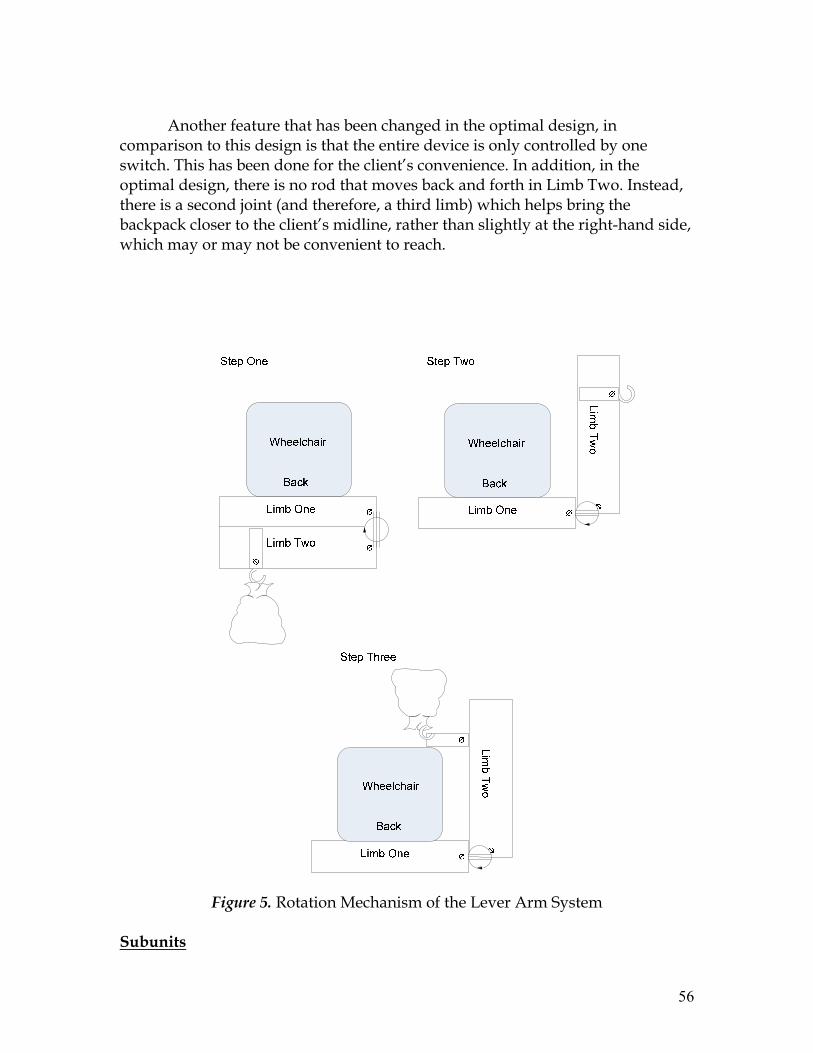
56
Another feature that has been changed in the optimal design, in comparison to this design is that the entire device is only controlled by one switch. This has been done for the client’s convenience. In addition, in the optimal design, there is no rod that moves back and forth in Limb Two. Instead, there is a second joint (and therefore, a third limb) which helps bring the backpack closer to the client’s midline, rather than slightly at the right-hand side, which may or may not be convenient to reach.
Figure 5. Rotation Mechanism of the Lever Arm System
Subunits

57
Motor
The team plans to use the 10A-TTL-3SW stepper motor by Excitron. Motions are precise, and the need for an angle measurement device is eliminated. This motor moves .9 degrees per step. Given this information, a microcontroller (described below) can be appropriately programmed and used. A given number of pulses will be sent to the motor so as to ensure it only moves the proper amount. In this setup, there will be two motors, one for each hinge. These are ideal for the design, as the correct amount of torque is provided to ensure that the arm rotates out consistently (without complication such as overheating of gear shredding). In terms of a power source, these motors require 12 volts to operate; however 24 volts is recommended. This should be easily provided by an external battery pack. The motor is also relatively light at 1 pound so it should not put any extra strain on the actual lever arm assembly.
Figure 6. Stepper Motor (with controller) ii
Microcontroller
The microcontroller that is ideal for application to this project is the
PIC18F1230. This chip enables customization and self programming based on the mode that it is put into. It also features pin break-out so that it is easy to use with a protoboard. There is a potentiometer that is used to control a 10-bit analog-to-digital input channel. The microcontroller consists of two external clock modes and two external RC modes. However the two most pertinent aspects of this chip are the internal oscillator and the flash memory module.

58
Figure 7. Microcontroller iii
The internal oscillator block can provide a 8 MHz clock as well as a range
of six selectable frequencies between 125kHz to 4MHz. This provides the correct movement sequence to the stepper motors that are involved in the joint articulation. A specific interval of time can be programmed for each of the stepper motors to be active. This way there will be precise, repeatable movements of the lever arm. Lever Arms
In terms of exact location and of the device, dimensions of the client’s
wheelchair, the Quickie-500, must be taken into account. The seat has an adjustable width of between 12’’-14’’; the depth of the seat is adjustable between 10’’-15’’. Taking these figures into account, it becomes easier to specify lengths of the individual arm components. In this design, the first limb of the arm, which is attached to the back of the wheelchair is 14 inches in length. Limb Two will be about 15 inches in length and 4 inches in width. The rod that is hidden inside of Limb Two will be 4 inches in length, and when it moves out, it is capable of bringing the backpack close to Mason’s mid-line. The height of these steel rods (used to form the limbs) will be 2 inches.
The foldable arm itself will be made of low carbon steel because of it is light, malleable and inexpensive. These properties are extremely critical because the addition of the device should not affect the balance of the wheelchair.
As far as determining the placement of the hook that will attach the backpack to limb three, torque must be taken into account. Client requested a device that will hold approximately 30 lbs, thus the torque will be calculated based on that weight. Torque is the measurement of the force acting on an object causing it to rotate. It is the cross product of distance vector and force vector.
Ƭ0 = r X F

59
Figure 8. Torque caused by Force (F)
As mentioned previously, the length of limb two is 15 inches. Hinge one acts as the pivot point, and weight of the backpack 30 lbs is the only force that will produce the torque. The following torque calculations were made based on the free body diagram. The small protruding rod
Figure 9. Free Body Diagram of limb Two
The backpack is hangs about one inch away from the end of limb 2, off of
the protruding rod; therefore, the torque at the hinge joint connecting limbs 1 and 2 is τ = r x F = 14 in. x 30 lb = 420 lb in
Considering that the shear strength of the hinge (the point of connection), which is made out of brass is 200-400 MPa, which is many orders of magnitude

60
above the torque value calculated, it is safe to assume that the device will be able to easily sustain the load.
The foldable arm itself will be made of low carbon steel because of it is light, malleable and inexpensive. These properties are extremely critical because the addition of the device should not affect the balance of the wheelchair. The project has a relatively low budget, therefore the inexpensive nature of low carbon steel is also important. The team has decided to use the hot rolled square low carbon steel bars from Chapin & Bangs. Control Switches In this design, the control switches are wired directly to the system. Their individual functions are described in the diagrams shown previously. In terms of the location of the switches, the team expects that Mason will attach the Velcro strap to his right arm rest, as this is his functional arm. It will be placed at a location that does not hinder his movement or ability to use writing utensils. Generally, this tends to be towards the far end of the arm rest. Clipper
The H.B. Clipper Quickdraw will be used to hold the backpack in place. In addition to being capable of supporting a heavy load, this will enable convenient attachment/detachment of the backpack in case there is a need. In terms of materials, the clippers are made of stainless steel, which is corrosion-resistant. This will improve the safety and product life the device. The two clippers are connected by a strong, 13 cm nylon string. Since this device is meant to be used for climbing, it is capable of handling various degrees of strain, as well as different climatic conditions. This durability will prove to be a positive feature of the device. In addition, it is essential to realize that the H.B. Clipper Quickdraw is light in weight, and will not significantly add to the weight of the entire device. It is a mere 4.8 oz, which is great when attention is directed to the amount of strength that it adds to the entire system. In terms of the exact location on the backpack lever arm, the H.B. Clipper Quickdraw will be placed on the metal piece, moving in and out of rotating limb. One clipper will be used to attach the backpack whereas the other will be used to attach to the metal piece.

61
Figure 10. Clipper Quickdraw Device [3] Supports
The component used to attach the device to the wheelchair is a vital part of the system. It is absolutely necessary that it be placed at locations that provide maximum stability. In addition, materials that form the support must possess high mechanical strength. The team plans to use low-carbon steel to build an attachment/support device, which will provide adequate strength to the design.
After a careful analysis of the client’s wheelchair and the environment in
which the device plans to operate (on the basis of pictures sent by the client’s family as well as a review of on-line information posted by the manufacturer), it seems appropriate to incorporate a horizontal bar support at the back of the client’s wheelchair. Since Quickie Z-500’s seat width is (12-14 in.), the horizontal support bar will be adjustable to accommodate sizes in between. This will be taken care of by inserting rods of varying lengths into the vertical adjustment holes, based on the client’s requirement. The bar will be locked on both sides to the vertical adjustment pieces, generally used to adjust the height of armrest clamps.
If the wheelchair needs to be adjusted, the support can be removed and
placed at a level that the client feels is appropriate. The horizontal support will serve as the location to which the first segment (path for the wheel) is attached. The support piece will be attached to the path at four points, equidistant from each other along the path. Screws will be placed on each to ensure that fixation has taken place.
Primarily, the vertical adjustment holes will bear the greatest force, which
will be in the downwards direction. It is also essential that the rods inserted in the vertical adjustment holes have sufficient shear strength, since this is the type

62
of force they will be experiencing. The team plans to use 304 stainless steel, as it will be more than sufficient in meeting strength requirements. The shear strength of 304 stainless steel has been noted to be 186 MPa. [2]
Figure 11. Visual representation (back view) of the wheelchair with lever arm.
Design 2 Objective
This design is unique in its ability to utilize space above the client, rather
than relying on sufficient space on the sides. It is only similar to the previously proposed designs in that the final position of the backpack will be at the client’s midline. This design will differ in the mechanism through which the backpack is moved towards the client’s midline. This involves a different method of motion, and does not utilize some components of the initial design, such as the motorized wheel. In addition, the device does not move along the client’s side, but sufficiently above his head. In comparison to the initial designs, the current alternative has the potential to be more efficient in terms of space utility. Previously, vacant space of approximately four feet along the client’s periphery was necessary for proper function of the device. In a packed classroom setting, this requirement may be difficult to meet. In terms of safety, it is vital to note that the currently proposed foldable device uses vertical space, and poses less of a hazard to individuals within close proximity. Additionally, the device will be stored and folded (in entirety) at the back of the wheelchair.

63
The device will involve a motorized telescopic pole, attached to the back of the wheelchair. A rotational limb will be attached to the end of the pole. When it is not being used, the rotational limb will lie in the horizontal plane, and point to in the right-hand direction. For purposes of functionality, it will be capable of revolving ninety degrees in the clockwise and counter-clockwise direction. The rotational limb will be connected to one more limb (capable of parallel movement) via a hinge. The purpose of this is to allow sufficient horizontal distance between the client and backpack when the telescopic pole (raising the backpack) is lowered. This mechanism will bring the backpack close to the client’s midline (upper-abdominal – lower-thoracic level). It will be the final position of the device. From here, the client may remove or place belongings as he wishes.
Figure 12. The back view of the device at resting position

64
To describe the functioning of the device in sequence, it starts with a user stimulus. When Mason wishes to obtain items from his backpack, he will turn Switch 1 located on a remote controller (which is attached by a Velcro strap to his right arm chair). The motorized telescopic pole (to which the limbs are attached) will slowly extend upwards, ending at a position that is 4 feet above the wheelchair’s height. Assuming a standard-sized school backpack that is less than 3 feet in length, sufficient space (6-12 inches) will remain between the client’s head and the base of the backpack.
Following this movement, the rotational limb (parallel to the floor and
initially pointing in the right hand-direction) will move 90 degrees in the counter-clockwise direction. After this, the other limb (attached to the first limb via a hinge) will extend 180 degrees in a counter-clockwise direction. Finally, the telescopic pole will move downwards, lowering the base of the extended backpack to his chest –line. At this point, the extended arm will be 6 inches above his head. As both limbs are equal in length (1 foot), their combined extension will provide 2 feet horizontal space between the client’s backrest and the backpack.
Once he has removed/replaced the desired items from his backpack,
Mason will turn Switch 1 on the remote control. This will reverse the movement of the telescopic pole and limbs. A final, collapsible position will result, in which the device and backpack are conveniently located at the rear of the wheelchair.
Figure 13. Flow Chart for device operation 2.1.2.2 Subunits 1.1.1 Rotational Telescopic Pole For the current design a telescopic pole will be implemented in order to raise a level arm system over the clients head. This lever arm portion will then extend out to a position that will place the backpack in at the client midsection. The telescopic pole will then lower the backpack so that it is in front of the client.

65
The telescopic pole that is planned for use in this project is the HTR dynamic telescoping actuator model T3B050. It is made to raise objects weighing up to 110 pounds. It can also extend up to eight feet. This will allow ample space for the backpack to clear the clients head. The accuracy of this actuator is also roughly .008 inches, which means that the pole should consistently work in the manner proposed.
Figure 14. HTR Telescopic Pole
The pole is more than capable of meeting the needs of this project so the next step is how it will be used. The manufacturer offers different gears on the system so that it can be lowered and raised at different speeds. The weight of the unit is only 25 pounds so it is fairly light compared to the weight that it can lift. The extension is governed by sensors on the pole. The telescopic pole will be bolted to the back of the wheelchair using by using one of the rails on the back. It will be mounted so that when the pole is retracted it will fit completely behind the back of the chair. This way it will not impede the client’s ability to move or be a danger to anyone walking around the wheelchair. Once the pole is completely extended the lever arm will activate. Stepper Motor

66
The team plans to use the 10A-TTL-3SW stepper motor by Excitron. Motions are precise, and the need for an angle measurement device is eliminated. This motor moves .9 degrees per step. Given this information, a microcontroller (described below) can be appropriately programmed and used. A given number of pulses will be sent to the motor so as to ensure it only moves the proper amount. In this setup, there will be two motors, one for each hinge. These are ideal for the design, as the correct amount of torque is provided to ensure that the arm rotates out consistently (without complication such as overheating of gear shredding). In terms of a power source, these motors require 12 volts to operate; however 24 volts is recommended. This should be easily provided by an external battery pack. The motor is also relatively light at 1 pound so it should not put any extra strain on the actual lever arm assembly.
Figure 15. Stepper Motor (with controller) iv
Microcontroller
The microcontroller that is ideal for application to this project is the
PIC18F1230. This chip offers the ability to of customization and self programming based on the mode that it is put into. It also features pin break-out so that it is easy to use with a protoboard. There is also a built in potentiometer that is used to control a 10-bit analog-to-digital input channel. The microcontroller consists of two external clock modes and two external RC modes. However the two most pertinent aspects of this chip are the internal oscillator and the flash memory module.

67
Figure 16. Microcontroller
The internal oscillator block can provide an 8 MHz clock as well as a range
of six selectable frequencies between 125kHz to 4MHz. This feature will easily be utilized for providing the correct movement sequence to the stepper motors that are involved in the joint articulation. A specific interval of time can be programmed for each of the stepper motors to be active. This way there will be precise, repeatable movements of the lever arm.
Figure 17. Microcontroller Cicruit Design

68
Lever Arm
The foldable arm will involve a single-hinge joint at an appropriate position on the arm to allow for horizontal planar motion. The arm will have one joint, connecting two limbs. It is attached to the end of the Rotational Telescopic Pole, parallel to the floor and pointing in the right hand direction at resting position. During the operation of the device, both Limbs will rotate about the hinges in order to bring the backpack to the front of the client. The backpack is attached to Limb Two via an attachment accessory, such as a clipper.
To describe the functioning of the arm in sequence, it starts after the
Rotational Telescopic Pole rises and locks into place. Limb One will rotate 90 degrees counterclockwise about Hinge One. Limb Two will then rotate about Hinge Two 180 degrees in a counter-clockwise direction from the folding parallel position to directly in front of Limb One. Once the limb has reached its final position and locked into place, Mason will turn switch one more time to have the Rotational Telescopic Pole lowers to 6 inches above his head.
Once he has removed/replaced the desired items from his backpack,
Mason will turn switch on the wireless remote control to raise the Rotational Telescopic Pole, followed by the 180 degrees rotation of Limb Two in a clockwise direction to attain a folded position. Then both Limbs will rotate 90 degrees clockwise about Hinge One to bring the whole device behind the wheelchair. Once this has been achieved, the Rotational Telescopic Pole will lower to the original storage position.
The followings are visual representations of how the rotational arm part of the device is supposed to function. Figure 18 illustrates the arm and its rotation mechanism. The upper block diagram indicates the movement to bring the backpack from its initial position at the back of the wheelchair to the front – to our client’s mid-body level. The lower block diagram shows how, upon stimulus, the backpack returns to its initial position behind the wheelchair, followed by folding of the arm into a convenient and ‘collapsed’ position.

69
ØLi
mb
One
ØLi
mb
Two
Figure 18. Rotation Mechanism of the Lever Arm System

70
Figure 19. Flow Chart of Lever Arm Operation
In terms of exact location and of the device, dimensions of the client’s
wheelchair, the Quickie-500, must be taken into account. The seat has an adjustable width of between 12’’-14’’; the depth of the seat is adjustable between 10’’-15’’. Taking these figures into account, it becomes easier to specify lengths of the individual arm components. In this design, both limb will be equal in length (1 foot), their combined extension will provide 2 feet horizontal space between the client's backrest and the backpack, and will not exceed the depth of the seat.
As far as determining the placement of the hook that will attach the
backpack to Limb Two, torque must be taken into account. Client requested a device that will hold approximately 30 lbs, thus the torque will be calculated

71
based on that weight. Torque is the measurement of the force acting on an object causing it to rotate. It is the cross product of distance vector and force vector.
Ƭ = r X F
Figure 20. Torque caused by Force (F)
As mentioned previously, the length of Limb Two is one foot or 0.3048
meters. Hinge Two acts as the pivot point, and weight of the backpack 30 lbs is the only force that will produce the torque. The following torque calculations were made based on the free body diagram.

72
Pivot point (Hinge Two)
Ø
Figure 21. Free Body Diagram of Limb Two
The backpack is hanging ¾ away from Hinge Two,
.56.30
)8.9)(64.13()3048.0(43
MN
Fr
•=
×=
×=
τ
τ
τ
Considering that the shear strength of the hinge (the point of connection),
which is made out of brass is 200-400 MPa, which is many orders of magnitude above the torque value calculated, it is safe to assume that the device will be able to easily sustain the load.
The foldable arm itself will be made of low carbon steel because of it is light, malleable and inexpensive. These properties are extremely critical because the addition of the device should not affect the balance of the wheelchair. The project has a relatively low budget of $750, therefore the inexpensive nature of low carbon steel is also important. Clipper
The H.B. Clipper Quickdraw will be used to hold the backpack in place. In addition to being capable of supporting a heavy load, this will enable convenient attachment/detachment of the backpack in case there is a need. In terms of materials, the clippers are made of stainless steel, which is corrosion-resistant. This will improve the safety and product life the device. The two clippers are connected by a strong, 13 cm nylon string. Since this device is meant to be used

73
for climbing, it is capable of handling various degrees of strain, as well as different climatic conditions. This durability will prove to be a positive feature of the device. In addition, it is essential to realize that the H.B. Clipper Quickdraw is light in weight, and will not significantly add to the weight of the entire device. It is a mere 4.8 oz, which is great when attention is directed to the amount of strength that it adds to the entire system. In terms of the exact location on the backpack lever arm, the H.B. Clipper Quickdraw will be placed on the metal piece, moving in and out of rotating limb. One clipper will be used to attach the backpack whereas the other will be used to attach to the metal piece.
Figure 22. Clipper Quickdraw Device [3] Supports
The component used to attach the device to the wheelchair is a vital part of the system. It is absolutely necessary that it be placed at locations that provide maximum stability. In addition, materials that form the support must possess high mechanical strength. The team plans to use low-carbon steel to build an attachment/support device, which will provide adequate strength to the design.
After a careful analysis of the client’s wheelchair and the environment in
which the device plans to operate (on the basis of pictures sent by the client’s family as well as a review of on-line information posted by the manufacturer), it seems appropriate to incorporate a horizontal bar support at the back of the client’s wheelchair. Since Quickie Z-500’s seat width is (12-14 in.), the horizontal support bar will be adjustable to accommodate sizes in between. This will be taken care of by inserting rods of varying lengths into the vertical adjustment holes, based on the client’s requirement. The bar will be locked on both sides to

74
the vertical adjustment pieces, generally used to adjust the height of armrest clamps.
If the wheelchair needs to be adjusted, the support can be removed and
placed at a level that the client feels is appropriate. The horizontal support will serve as the location to which the first segment (path for the wheel) is attached. The support piece will be attached to the path at four points, equidistant from each other along the path. Screws will be placed on each to ensure that fixation has taken place.
Primarily, the vertical adjustment holes will bear the greatest force, which
will be in the downwards direction. It is also essential that the rods inserted in the vertical adjustment holes have sufficient shear strength, since this is the type of force they will be experiencing. The team plans to use 304 stainless steel, as it will be more than sufficient in meeting strength requirements. The shear strength of 304 stainless steel has been noted to be 186 MPa. [2] Design 3 Objectives
Similar to the initial design, the backpack lever arm be designed to take advantage of the client’s functional right arm. In addition, it is similar in the fact that it will use a curved path, upon which a wheel will roll from the rear of the wheelchair to the client’s midline. However, the method of operation for this design is unique and completely different from any of the other proposed alternatives. This design seeks to eliminate every electrical component, and make the device purely mechanical. As it will be operated by the client, functionality and operation of the device is largely dependent on the user. A significant challenge that the group faced in developing a product was to ensure that a minimal force input was required from the client.
However, by creating a mechanical design, the team is eliminating any
safety concerns that would need to be taken into account otherwise. In addition, benefits include the fact that there is minimal maintenance in a mechanical design, which would require occasional oiling for smooth movement. In the case of an electrical design, rechargeable batteries would be required, as well as the help of a family member/friend to help the client his device into a power socket.
The foldable arm will involve one hinge joint at an appropriate position
on the arm to allow for horizontal planar motion. The arm will have one joint, connecting two limbs. One limb (L-shaped) will remain attached to the back of Mason’s wheelchair (at a height level that approximately 6 inches above that of his armrest). The first movement will involve rotation about one hinge to bring

75
the rotational limb in a position that is perpendicular to the client’s armrest, and horizontally about one foot away from the client’s midline. This refers to the upper-abdominal – lower-thoracic level. The second motion will involve movement of the client’s backpack from the rear of the wheelchair to the front, along a curved path. This occurs, as the rolling wheel (to which the backpack is attached) runs along the inner surface of the curved path. This will serve as the final position of the device. From here, the client may remove or place belongings as he wishes.
Client Moves Rotational Limb
(Using Handle), 270 Degrees In A
Counter-Clockwise Direction
Client Rotates Sailing Wench To
Move The Backpack Along The Curved
Path
Final Position Of Backpack Is In Front Of The Client, At His
Midline
Figure 23. Flow Chart for device operation Winch
The system devised will incorporate a fully mechanical method for
transferring the client’s backpack to a position that is comfortable for use. A sailing winch will be utilized to move the backpack by wrapping a loop around the winch and connecting the other ends of the rope to the wheels of the backpack hanger. This will make a second bigger loop. As the winch is cranked clockwise it will move the smaller loop that is around the winch and in turn bring the backpack closer to the client. When the winch is rotated in the other direction the wheels (and backpack) will move back the other way.

76
Figure 24. Winch with Looped Rope System
The winch that will be used is the Harken # 6 Single-speed Winch model number
HARB6A. This winch is ideal because it is a compact size and it only weighs 1.5 pounds. The winches drum diameter is 2.75 inches and the base diameter is a little over 3.5 inches. These dimensions will allow for the winch to be securely fastened to the wheelchair’s armrest. The height of the drum is only 3.25 inches, which coupled with the height of the crank will make it in an ideal position for the client to use comfortably. The winch is also more than capable of applying the needed force to move the backpack. The winch has a power ratio of 8.1:1. This means that for every pounds per foot that is applied to the winch 8 pounds is applied to the drum. This is due to the fact that the winch is composed of gears that will multiply force. Based of the equation for work we know that:
Work = Force x Distance
Based on this law we can say that is the power ration is 8.4:1 than the rotational distance of the gears is 1:8.4. This way the conservation of energy law is upheld. The way in which the transfer will work will be with a rope connected to the axle of the rolling wheels. In order to ensure that the devise functions properly and consistently there must always be tension in the rope. This will be provided by the use of pulley wheels. The wheels will guarantee that the rope is always lined up along the track and that there is constant tension. Pulley Wheels The pulleys that will be used for the devise will be plastic round belt pulleys. These are ideal because they are designed for use with standard nylon ropes. The pulley wheels will a be setup on the inside of curves in the rollers

77
path. This way they will ensure that the rope stays taught and that is follows a particular path. The curve for the rope in the pulley will be design for a 1/4 inch rope to be used. The rope will be discussed further in the next section. The particular wheels that will be used in this project are made by POBCO Plastics. The model number is 1/4C240804. This particular model has a 1.5 inch over all diameter, which makes it small enough to be used in this project. The most complex scenario will be the guide rope around the hinge joint in the lever arm. This will have to be composed of two pulley wheels put together as shown in the figure below.
Figure 25. Example of guide pulley setup
Rope
The rope that will be used for this project is that is a ¼ inch 3 twist nylon rope. These ropes are specifically designed for to be used in high load situation but have minimal weight. The min tensile strength of this rope is 1650 lbs, which is more than enough to handle the backpack. Nylon is also an ideal material because it has a low coefficient of friction: 0.15 - 0.25. This means that it will take little effort to actually move the rope and cause less wear on the rope, pulley wheels and winch drum.
Figure 26. Nylon 3 twist rope.

78
Lever Arms
The foldable arm will involve a single-hinge joint at an appropriate position on the arm to allow for horizontal planar motion. The arm will have one joint, connecting two limbs. Limb one will be L-shaped and remain attached to the back of Mason’s wheelchair (at a height level that approximately 6 inches above that of his arm rest) and the other (Limb Two) will rotate to create a track n which the roller will move. The end of the arm will serve as the final position for the roller. The backpack will be attached will be fastened to the roller wheel via an attachment accessory, such as a clipper.
The followings are visual representations of how the device is supposed to
function. Figure 3 illustrates the Lever Arm System and its rotation mechanism. The upper block diagram indicates the movement to bring the backpack from its initial position at the back of the wheelchair to the front – to our client’s mid-body level. The lower block diagram shows how, upon stimulus, the backpack returns to its initial position behind the wheelchair, followed by folding of the arm into a convenient and ‘collapsed’ position.
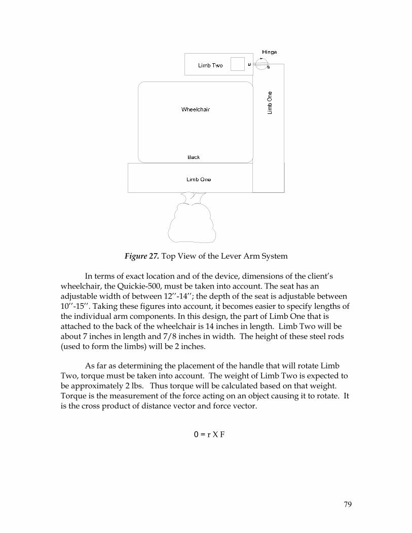
79
Figure 27. Top View of the Lever Arm System
In terms of exact location and of the device, dimensions of the client’s
wheelchair, the Quickie-500, must be taken into account. The seat has an adjustable width of between 12’’-14’’; the depth of the seat is adjustable between 10’’-15’’. Taking these figures into account, it becomes easier to specify lengths of the individual arm components. In this design, the part of Limb One that is attached to the back of the wheelchair is 14 inches in length. Limb Two will be about 7 inches in length and 7/8 inches in width. The height of these steel rods (used to form the limbs) will be 2 inches.
As far as determining the placement of the handle that will rotate Limb Two, torque must be taken into account. The weight of Limb Two is expected to be approximately 2 lbs. Thus torque will be calculated based on that weight. Torque is the measurement of the force acting on an object causing it to rotate. It is the cross product of distance vector and force vector.
�0 = r X F

80
Figure 28. Torque caused by Force (F)
As mentioned previously, the length of Limb Two is 7 inches or 0.1778 meters. The Hinge acts as the pivot point, and weight of the Limb Two 2lbs is the only force that will produce the torque. The following torque calculations were made based on the free body diagram.
Pivot point (Hinge)
Ø
Figure 29. Free Body Diagram of Limb Two

81
The backpack is hanging 1/4 away from Hinge Two,
.3952.
)8.9)(9072.0()1778.0(41
MN
Fr
•=
×=
×=
τ
τ
τ
The foldable arm itself will be made of low carbon steel because of it is
light, malleable and inexpensive. These properties are extremely critical because the addition of the device should not affect the balance of the wheelchair. The project has a relatively low budget of $750, therefore the inexpensive nature of low carbon steel is also important. Hinge
The hinge that will be used to attach Limb One and Two has to have the capability of rotating 270 degrees both counter clock and clock wise. The team decided to use 270 degree overlay hinge supplied by Hardware Source. It is made of brass, and only costs $17.97. The dimensions of the hinge are 1-9/16” tall, 1” deep, 1-3/8” long. It has a limitation on size of bar attached, and it can be up to 7/8” thick
Figure 30. 270 degree overlay hinge
Attachment of backpack The H.B. Clipper Quickdraw will be used to hold the backpack in place. In
addition to being capable of supporting a heavy load, this will enable convenient attachment/detachment of the backpack in case there is a need. In terms of materials, the clippers are made of stainless steel, which is corrosion-resistant. In addition, it is essential to realize that the H.B. Clipper Quickdraw is light in

82
weight, and will not significantly add to the weight of the entire device. It is a mere 4.8 oz, which is great when attention is directed to the amount of strength that it adds to the entire system.
Figure 31. Clipper Quickdraw Device [3] In terms of the exact location on the backpack lever arm, the H.B. Clipper Quickdraw will be attached to a protruding piece, located at the wheel’s axle. One clipper will be used to attach the backpack whereas the other will be used to attach to the protruding piece. As shown below, a torque of 150 lb.in will be exerted about the point at the center of the wheel. However, since the path about which the wheel moves is a carved out metal arm, into which the wheel fits, it adheres to its ‘track’ on the top and bottom sides. Thus, there is no possibility of the wheel slipping out of the track. In a static position, the torque is balanced by the force being exerted from the metal track to the wheel itself, helping maintain equilibrium.
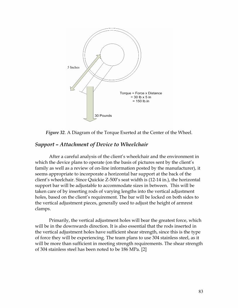
83
Figure 32. A Diagram of the Torque Exerted at the Center of the Wheel.
Support – Attachment of Device to Wheelchair
After a careful analysis of the client’s wheelchair and the environment in
which the device plans to operate (on the basis of pictures sent by the client’s family as well as a review of on-line information posted by the manufacturer), it seems appropriate to incorporate a horizontal bar support at the back of the client’s wheelchair. Since Quickie Z-500’s seat width is (12-14 in.), the horizontal support bar will be adjustable to accommodate sizes in between. This will be taken care of by inserting rods of varying lengths into the vertical adjustment holes, based on the client’s requirement. The bar will be locked on both sides to the vertical adjustment pieces, generally used to adjust the height of armrest clamps.
Primarily, the vertical adjustment holes will bear the greatest force, which
will be in the downwards direction. It is also essential that the rods inserted in the vertical adjustment holes have sufficient shear strength, since this is the type of force they will be experiencing. The team plans to use 304 stainless steel, as it will be more than sufficient in meeting strength requirements. The shear strength of 304 stainless steel has been noted to be 186 MPa. [2]

84
Low -Carbon SteelSupport Bar
Vertical Adjustment Holes (Sides of
Wheelchair)
Segment of Pathway For Wheels
Four Equidistant Holes for Attachment of Arm Segment to
Wheelchair
2 Inches
12-14 Inches (Adjustable)
Figure 33. (Back View) – Above is a figure that gives a visual representation of
how the backpack lever arm will attach to the wheelchair. An adjustable horizontal support, fixed to vertical adjustment holes through the use of stainless steel rods will connect at four equidistant points to the arm segment.
Figure 34. Adjustment Holes for the Armrest

85
2.2 Optimal Design 2.2.1 Objective
The device is an electrically operated lever arm, capable of moving the client’s belongings to an accessible position. The design will make use of the client’s functional right arm, as this was requested by the family. The device will remain at an ideal distance away from the client, close enough to allow utilization of his arm’s abilities and far enough to not cause inconvenience to his own movement. It will also account for the safety of those in close proximity, whether class associates or family members.
After evaluating a purely mechanical design, and various electrical
designs that incorporate multiple controls, it has been decided that a single switch mechanism (electrical) will be used to conveniently position the device at Mason’s lower thoracic/upper abdominal level for optimal comfort. One of the clients’ requests is that the backpack be brought close to the body’s midline.
In a position of non-use, the limbs fold into a compact position at the rear
of the client’s wheelchair. A simple ‘ON/OFF’ switch will control the movement of the limbs, which will sequentially unfold to obtain the position desired. The first Limb is securely fastened to the back of the wheelchair. Limbs 2 and 3 rotate (in that order) in a counterclockwise fashion upon client stimulus to bring the backpack into the position desired. This process is described in extensive detail further in the report.

86
Low -Carbon SteelSupport Bar
Vertical Adjustment Holes (Sides of
Wheelchair)
12-14 Inches (Adjustable)
20 Inches
9 Inches
Armrest
6 Inches
Figure 35. Visual representation (back view) of the wheelchair with lever arm. 2.2.2 Subunits 2.2.2.1 Voltage Controller
The power delivery for this kit will provided by a 24V source from the clients wheel chair routed through a voltage regulator. The importance of a voltage regulator is that unlike using a direct voltage source, the voltage regulator does not allow for fluctuations in the voltage or current that it outputs.
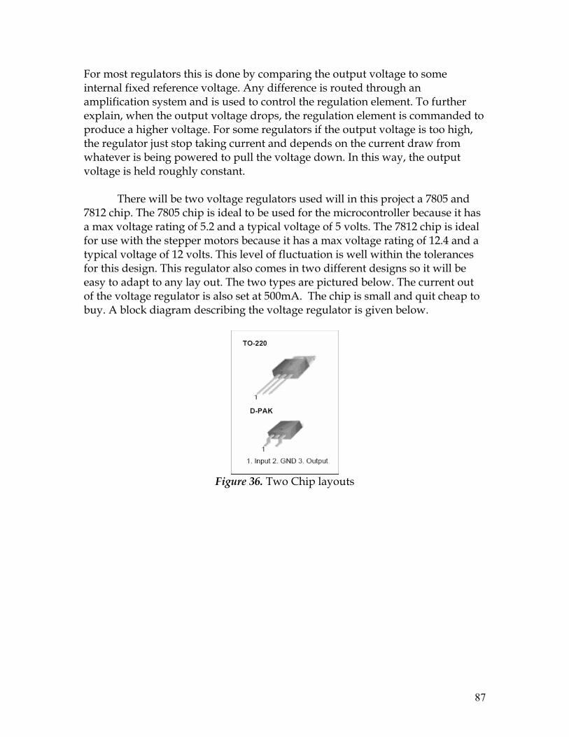
87
For most regulators this is done by comparing the output voltage to some internal fixed reference voltage. Any difference is routed through an amplification system and is used to control the regulation element. To further explain, when the output voltage drops, the regulation element is commanded to produce a higher voltage. For some regulators if the output voltage is too high, the regulator just stop taking current and depends on the current draw from whatever is being powered to pull the voltage down. In this way, the output voltage is held roughly constant.
There will be two voltage regulators used will in this project a 7805 and
7812 chip. The 7805 chip is ideal to be used for the microcontroller because it has a max voltage rating of 5.2 and a typical voltage of 5 volts. The 7812 chip is ideal for use with the stepper motors because it has a max voltage rating of 12.4 and a typical voltage of 12 volts. This level of fluctuation is well within the tolerances for this design. This regulator also comes in two different designs so it will be easy to adapt to any lay out. The two types are pictured below. The current out of the voltage regulator is also set at 500mA. The chip is small and quit cheap to buy. A block diagram describing the voltage regulator is given below.
Figure 36. Two Chip layouts

88
Figure 37. Block Diagram
2.2.2.2 Microcontroller
The microcontroller that is ideal for application to this project is the
PIC16F84. This chip offers the ability of customization and self programming based on the mode that it is put into. The PIC16C84 is a low-cost, high-performance, CMOS, fully-static, 8-bit microcontroller. All PIC16Fxx microcontrollers employ an advanced RISC architecture. PIC16CXX devices have enhanced core features, eight-level deep stack, and multiple internal and external interrupt sources. The separate instruction and data buses of the Harvard architecture allow a 14-bit wide instruction word with a separate 8-bit wide data bus. The two stage instruction pipeline allows all instructions to execute in a single cycle making the chip significantly fast then previous models. A total of 35 integrated instructions are available. Additionally, a large register set is used to achieve a very high performance level. The chip also only use 5.0Volts
PIC16CXX microcontrollers typically achieve a 2:1 code compression and
up to a 2:1 speed improvement (at 10 MHz) over other 8-bit microcontrollers in their class. The PIC16C84 has 36 bytes of RAM, 64 bytes of Data EEPROM memory, and 13 I/O pins. A timer/counter is also available. The PIC16CXX microcontrollers also have special features to reduce external component use. This is important because it reduces the cost needed to create various devices. It also improves reliability and reduces cost of any project. The power consumption of the device is also greatly reduced by its interrogated design. This is of great concern for this project because the client cannot constantly recharge the battery pack. The unit also offers a SLEEP mode, which can reduce power consumption greatly. The user can wake the chip from sleep through several external and internal interrupts and resets.

89
The chip offers four oscillator options, of which the single pin RC oscillator provides a low-cost solution, the LP oscillator minimizes power consumption, XT is a standard crystal, and the HS is for High Speed crystals. These oscillators may be used to control the stepper motors as is explained in a later section. A highly reliable Watchdog Timer with its own on-chip RC oscillator provides protection against software lockup. This will make the chip incredibly reliable, which is important because the client will be using the device constantly. The PIC16C84 EEPROM program memory allows the same device package to be used for prototyping and development. Internal circuit reprogramability allows the code to be updated without the device being removed from the end application. If there are any problems once the chip is placed in the device if there are any problems this feature will make it easy to fix. This is useful in the development of many applications where the device may not be easily accessible, but the prototypes may require code updates.
The EEPROM technology makes customization of application programs
(transmitter codes, motor speeds, receiver frequencies, security codes, etc.) extremely fast and convenient. The small footprint packages make this microcontroller series perfect for all applications with space limitations. Low cost, low power, high performance, ease of use and I/O flexibility make the PIC16C84 very versatile. The serial in-system programming feature (via two pins) offers flexibility of customizing the product after complete assembly and testing. This feature can be used to serialize a product, store calibration data, or program the device with the current firmware before shipping.
Figure 38. Microcontroller

90
Figure 39. Block diagram of PIC16C84
2.1.2.3 Stepper Motor Controller
Below is a schematic of general setup of how a stepper motor can be controlled by the microcontroller we picked. The PIC's output lines are first buffered by a 4050 hex buffer chip, and are then connected to an NPN transistor. The transistor is a TIP120, which is actually a NPN Darlington. This is significant because the Darlington transistor main advantage is that it combines two bipolar transistors in a single device. In this setup the current is amplified by the first transistor and then amplified again by the second. This gives a high current gain and takes less space than two discrete transistors in the same configuration. For this circuit the TIP120's act like switches, activating one stepper motor coil at a time.
Figure 40. Darlington transistor

91
Figure 41. Circuit Diagram For Stepper Motor Controller.
When the coils are activated there is typically current spike. Due to this inductive surge that is created when a coil is toggled, a standard 1N4001 diode is usually placed across each transistor. This allows a safe way of channeling the reverse current without damaging the transistor. This is important because once the device is assembled it will be difficult to remove components in order to replace them. This setup is typically called a snubbing diode. However, because the transistors being used are TIP120 transistors there is no need do not need for an external snubbing diode. The TIP120 has a built in diode. The diodes shown in the diagram are simply a representation of the internal diodes.
The most convenient way to operate a stepper motor with a PIC microcontroller is with the full step pattern shown in the table below. Each part of the sequence turns on only one transistor at a time in a continuous sequence. This way the motor rotates smoothly. The chip is programmed so that the process is repeated until the microcontroller is told to stop. It also makes the control very efficient. As will be seen later the delay used in the program controls how much the motor will rotate. To increase the speed the delay can be lowered and vice-versa in order to slow the motor down.

92
Q1 Q2 Q3 Q4
+ - - -
- + - -
- - + -
- - - +
Figure 42. Step patern
Below is a demonstration of how easily a program can be written to control a stepper motor. The program uses a high and low command in order to tell each pin to go high or low. This particular program shows a complete loop as in there is no end to this process. However, by introducing a control loop the rotation of the device can be controlled. That is to say for example, that this process will only initiate 250 times and at that point the motor will have rotated 220 degrees.
' First stepper motor controller program ' Rotates motor at set speed forever Symbol delay = B0 ' use b0 as the delay variable delay = 25 ' set the delay to 25 ms loop: high 0 ' turn on Q1 pause delay ' wait 25 ms low 0 ' turn off Q1 high 1 ' turn on Q2 pause delay ' wait 25 ms low 1 ' turn off Q2 high 2 ' turn on Q3 pause delay ' wait 25 ms low 2 ' turn off Q3 high 3 ' turn on Q4 pause delay ' wait 25 ms low 3 ' turn off Q4 goto loop ' forever ----listing 1----
Figure 43. Sample program
2.1.2.4 Lever Arms
The foldable arm will involve single-hinge joints at appropriate positions on the arm to allow for horizontal planar motion. The arm will have two joint, connecting three limbs. Limb one will be attached to the back of Mason’s wheelchair (at a height level that approximately 6 inches above that of his arm rest) and the others (limb two and three) will rotate to bring the backpack to the

93
front as close to the client’s mid-line as possible. The backpack will be fastened to the lever arm via an attachment accessory, such as a clipper.
To describe the functioning of the device in sequence, it starts with a user
stimulus. When Mason wishes to obtain items from his backpack, he will turn the switch located on controller (which is attached by a Velcro strap to his right arm chair). This will trigger the step motors to rotate the lever arm.
First, Limb two will rotate about hinge one 180 degrees in a counter-
clockwise direction from the folding position. Then limb three will rotate 270 degrees counter clockwise about hinge two to the right of limb two to form an L-shape. After that, limb two will rotate once again about hinge one 90 degrees clock wise to bring the backpack that is attached to limb three as possible to the client’s mid-line as possible. The final positions of three limbs after the rotations are limb one remains attached to the back of the wheelchair, limb two is 6 inches directly above the right arm rest, and limb three is in font of Mason with the backpack attached to it.
Once he has removed/replaced the desired items from his backpack,
Mason will turn the switch to reverse the sequence of the rotations described previously to bring the backpack to the back of the wheelchair.
The followings are visual representations of how the device is supposed to function. Figure 3 illustrates the Lever Arm System and its rotation mechanism. The upper block diagram indicates the movement to bring the backpack from its initial position at the back of the wheelchair to the front – to our client’s mid-body level. The lower block diagram shows how, upon stimulus, the backpack returns to its initial position behind the wheelchair, followed by folding of the arm into a convenient and ‘collapsed’ position.
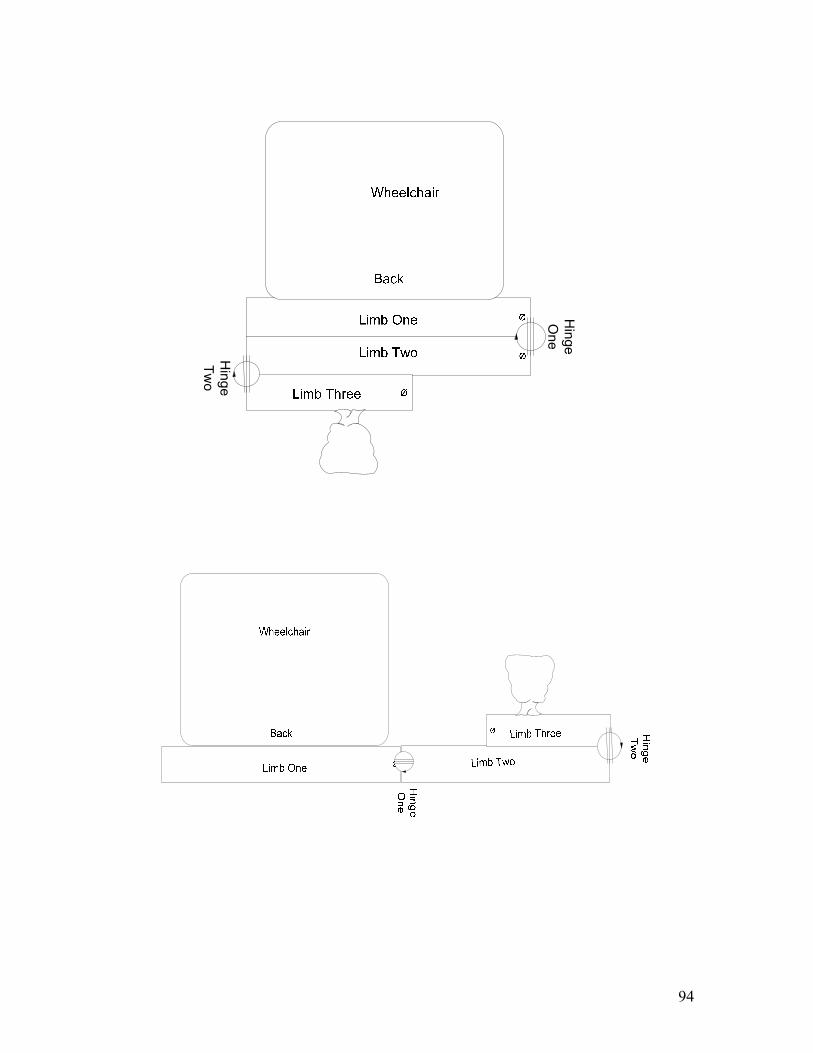
94
Hinge
One
Hinge
Two

95
Ø
Hinge
One
Hinge
Two
Limb Three
Figure 44. Top View of the Lever Arm System

96
Figure 45. Flow Chart of Lever Arm Operation
In terms of exact location and of the device, dimensions of the client’s wheelchair, the Quickie-500, must be taken into account. The seat has an adjustable width of between 12’’-14’’; the depth of the seat is adjustable between 10’’-15’’. Taking these figures into account, it becomes easier to specify lengths of the individual arm components. In this design, limb one that is attached to the back of the wheelchair is 14 inches in length. Limb Two will be about 14 inches in length and limb three will be 8 inches in length. The height of these steel rods (used to form the limbs) will be 2 inches, and the width will be 7/8’’.
As far as determining the placement of the hook that will attach the backpack to limb three, torque must be taken into account. Client requested a device that will hold approximately 30 lbs, thus the torque will be calculated based on that weight. Torque is the measurement of the force acting on an object causing it to rotate. It is the cross product of distance vector and force vector.
Τ0 = r X F

97
Figure 46. Torque caused by Force (F)
As mentioned previously, the length of limb three is one foot or 0.3048 meters. Hinge two acts as the pivot point, and weight of the backpack 30 lbs or 13.64 kg is the only force that will produce the torque. The following torque calculations were made based on the free body diagram.
Pivot point (Hinge Two)
Ø
Figure 47. Free Body Diagram of limb three

98
The backpack is hanging ¾ away from hinge two,
.56.30
)8.9)(64.13()3048.0(43
MN
Fr
•=
×=
×=
τ
τ
τ
Considering that the shear strength of the hinge (the point of connection),
which is made out of brass is 200-400 MPa, which is many orders of magnitude above the torque value calculated, it is safe to assume that the device will be able to easily sustain the load.
The foldable arm itself will be made of low carbon steel because of it is light, malleable and inexpensive. These properties are extremely critical because the addition of the device should not affect the balance of the wheelchair. The project has a relatively low budget of $750, therefore the inexpensive nature of low carbon steel is also important. The team has decided to use the hot rolled square low carbon steel bars from Chapin & Bangs. They are 7/8’’ in size which fits the requirements of the design. 2.1.2.4 Hinge
The backpack lever arm system requires two hinges, one attaches limb two to limb one, the other connects limb two and three. Please refer to figure 48 for the specific placements of the two hinges. These hinges need to have the capability to rotate 270 degrees both counter clock and clock wise to satisfy the forward and reverse movements of the lever arm.
The team decided to use 270 degree overlay hinge supplied by the
Hardware Source. It is made of brass, and costs $17.97 each. As mentioned previously the shear strength of brass is 200-400 MPa which is more than enough to handle the weight of the 30lb maximum weight that the client requested (please see the torque calculation above for proof). The dimensions of the hinge are 1-9/16” tall, 1” deep, and 1-3/8” long. It has a 7/8’’ limitation on the thickness of the bar attached. Therefore, the height of the lever arm cannot exceed 7/8’’.
Limb two is attached to the moving attachment piece of the hinge. The
fixed part of the hinge will be mounted to the end of the front right side of Limb One. In its closed state, the limb two remains rested parallel to limb one at the back of the wheelchair. The fixed part of the hinge two will be mounted to the other end of limb two, and the moving part will be attached to one end of limb three. When Mason wants to access his backpack, he will turn the switch. And
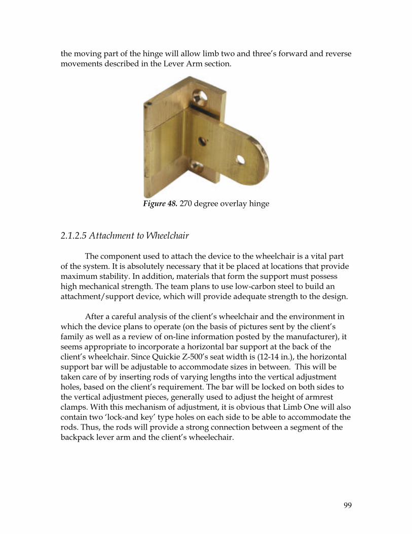
99
the moving part of the hinge will allow limb two and three’s forward and reverse movements described in the Lever Arm section.
Figure 48. 270 degree overlay hinge
2.1.2.5 Attachment to Wheelchair
The component used to attach the device to the wheelchair is a vital part of the system. It is absolutely necessary that it be placed at locations that provide maximum stability. In addition, materials that form the support must possess high mechanical strength. The team plans to use low-carbon steel to build an attachment/support device, which will provide adequate strength to the design.
After a careful analysis of the client’s wheelchair and the environment in
which the device plans to operate (on the basis of pictures sent by the client’s family as well as a review of on-line information posted by the manufacturer), it seems appropriate to incorporate a horizontal bar support at the back of the client’s wheelchair. Since Quickie Z-500’s seat width is (12-14 in.), the horizontal support bar will be adjustable to accommodate sizes in between. This will be taken care of by inserting rods of varying lengths into the vertical adjustment holes, based on the client’s requirement. The bar will be locked on both sides to the vertical adjustment pieces, generally used to adjust the height of armrest clamps. With this mechanism of adjustment, it is obvious that Limb One will also contain two ‘lock-and key’ type holes on each side to be able to accommodate the rods. Thus, the rods will provide a strong connection between a segment of the backpack lever arm and the client’s wheelechair.

100
Limb 1 (Attached to Back of Wheelchair)
HorizontalSupport
Rods
Vertical Holes On Bars That
Run Parallel On Either Side Of
The Wheelchair
Figure 49. Diagram showing the horizontal support rods, used to attach
the device to the back of the wheelchair. If the wheelchair needs to be adjusted, the support can be removed and
placed at a level that the client feels is appropriate. The horizontal support will serve as the location to which the first segment (path for the wheel) is attached. The support piece will be attached to the path at four points, equidistant from each other along the path.
Figure 50. Adjustment Holes for the Armrest

101
Primarily, the vertical adjustment holes will bear the greatest force, which will be in the downwards direction. It is also essential that the rods inserted in the vertical adjustment holes have sufficient shear strength, since this is the type of force they will be experiencing. The team plans to use 304 stainless steel, as it will be more than sufficient in meeting strength requirements. The shear strength of 304 stainless steel has been noted to be 186 MPa. [2] 2.1.2.6 Attachment of Backpack to Device
The H.B. Clipper Quickdraw will be used to hold the backpack in place. In
addition to being capable of supporting a heavy load, this will enable convenient attachment/detachment of the backpack in case there is a need. In terms of materials, the clippers are made of stainless steel, which is corrosion-resistant. This will improve the safety and product life the device. The two clippers are connected by a strong, 13 cm nylon string. Since this device is meant to be used for climbing, it is capable of handling various degrees of strain, as well as different climatic conditions. This durability will prove to be a positive feature of the device. In addition, it is essential to realize that the H.B. Clipper Quickdraw is light in weight, and will not significantly add to the weight of the entire device. It is a mere 4.8 oz, which is great when attention is directed to the amount of strength that it adds to the entire system.
Figure 51. Clipper Quickdraw Device [3] In terms of the exact location on the backpack lever arm, the H.B. Clipper Quickdraw will be attached to Limb 3, which is the segment that comes closest to the client’s midline. One clipper will be used to attach the backpack whereas the other will be used to attach to the limb. This will be done by making a small circular hole with a 1 inch diameter into one side of the limb.

102
3 Realistic Constraints
In today’s age it is not enough to just build an object, the affect it has on its surrounding must also be taken into account. Engineers are instructed to make sure that the products they design meet specific standards. Above all else their creations must do not harm others. They must also be efficient and affective for the potential users. In order to ensure that new products on the market adhere to all of the requirements there are engineering standards that are predetermined.
These guidelines are setup up by the government and engineering organizations. Some of organizations that specializing in creating and monitoring engineering standards include American National Standards Institute (ANSI), American Society for Quality (ASQ), Association for Advancement of Medical Instrumentation (AAMI), International Organization of Standardization (ISO), and National Institute of Standards and Technology (NIST). The approval of these groups is vital in the potential market reaction to any new product.v
For the Backpack Lever Arm System this means that it must meet all the
standards of any product on sale today. Since this is not just a prototype that will be used for testing, but instead a device that will directly impact the life of another person it must meet or exceed the benchmark that consumers have come to expect. The most relevant standards that this project must meet are specifically the ISO 9001:2000 Quality Management Systems (Requirements which provides systematic methods for managing all aspects of manufacturing a device), EN 1441:1997 Medical Devices (Risk Analysis), and EN 868-1:1997 (standardized packaging). However, these are not the only constraints that have been put on or project.
In terms of economic restrictions, the primary limitation is our allotted
budget of $750. The device that we plan to create must be affordable because it may hold potential to serve not only Mason, but other people living with cerebral palsy. The consumer market for a product such as ours will greatly vary in financial flexibility. So our charge is to design a device that is both effective and cost conscious. In this way we will ensure that the product will have a wide consumer bas.
Our device is essentially an electrically operated mechanical limb, capable
of moving Mason’s belongings to an accessible position. Given that we are combining two types of engineering into one device we must take care to ensure that these vastly different fields mesh together properly. This is not an easy task as there have been many instances where the outcomes of endeavors such as ours have been less than ideal.
103
4 Safety Issues
Ideas related to this design have been formed, taking into account the environment in which the device will operate. Primarily, this refers to the populated classroom/school setting, which will not only contain a higher density of individuals around the client, but other objects such as desks or learning materials. To avoid swinging metallic parts (lever arm) around the client’s periphery, the team has decided to minimize the range of the rotational motion by limiting the length of the limbs as short as possible so that injury to others is considerably reduced.
However, it is vital to examine the actual components of the device, in relation to the external environment (not necessarily indoor), and what repercussions changes in weather would have on the device’s functioning. It is necessary to make sure that mechanical and electrical components are reliable. The device might be exposed to heavy rain or other harsh weather conditions; to protect electrical components and ensure a long product-life, Teflon tape will be used to insulate. In addition, Neoprene rubber will be used to cover the device from the outside, eliminating water contact with internal components of the device. Nylon may also be used to cover the rotational and extension arm, as its properties make it resistant to abrasion and chemicals. These protective measures will make sure that the client is safe from electric and any injury associated with corrosion of device parts. 5 Impact of Engineering Solutions
Obviously any engineering solution that has been developed throughout history impacts humanity in many ways. These solutions are used so frequently that we can forget how much of they affect our daily lives. In the modern age not only do new products have the ability to make life easier, but they also are a testament to the technological advances that have been made in our time. The project discussed in this design paper is yet another indication of just how far engineering has come in the modern age. Creating a backpack transferring system that will assist the client in performing daily tasks will greatly improve his quality of life. Those around him may also begin to see the client in a different way. Without the need of others help the user will develop a sense of independence and accomplishment.
The impact can stretch much further to change the life of his family and potential many other individuals living with cerebral palsy. This global influence can even encompass persons with varying levels of cognitive impairment or

104
physical limitation. There are close to 100 million people with disabilities living in America today. Of those roughly 500,000 have cerebral palsy.
Involuntary movements and poor motor skills are the typical symptoms of
cerebral palsy. At present, about 2 out of 1000 children born in this country have some form of cerebral palsy. The trend is slowly decreasing, but the trend is still prevalent. Therefore the need for a device such as the one purposed in this text would bring great benefit to this community. However, this device is not limited to only persons with cerebral palsy. The system can be implemented by anyone who uses a wheel chair and has trouble with manipulation of heavy objects.
This device will bring independence to any client who wants it. Clients who live by themselves will benefit from the ability to transfer object to a position where they can use them. Our current project will be catered to or specific client and will be use to move a backpack to a comfortable position for him. However, it is definitely possible to diversify applications using the same basic concepts. A transfer device can be used in the home, office, workplace, or educational facility. When discussing engineering solutions in an economic context, it is natural to analyze the market and customer base. Generally, a conservative estimate is taken, in which it is projected that 10% of the customer base will be using the product within five years of release. This means that the potential number of clients for our product will be somewhere in the range of 50,000 people. This number may vary depending on the way that our product is marketed. As stated before the customer bases for our device should be quite extensive because of the potential applications. Depending on factors such as total costs, and the profit margins desired, a price a proper marketing approach could be decided upon.
The next step in to look at when bringing a new product to consumers is the global potential. The main issue to consider is financial flexibility of people outside our own economy. This problem however, should not be too detrimental as the estimated cost for our project will certainly be less than $750 US. This is a price that should be relatively affordable for a majority of people outside the United States. The last impact that needs s to be addressed is that of the environmental aspect.
In an environmental context, engineering solutions such as this do not seem to pose much of a threat. The materials planned for this device are all either made from recycled material are themselves recyclable. There is also no extra environmental concern about batteries since we plan on use the battery already implemented on the wheelchair. An optimal design plans to use a small voltage

105
of 12 volts. Therefore, it is unlikely that this problem will be significant enough to threaten natural surroundings in any way.
6. Life-long Learning
Life-long learning is a process that every individual experiences, whether by choice, or sub-consciously. It has the potential to strongly influence one’s perspective; here, what one learns through research and the input of others can significantly impact decisions that are made with regard to design.
Based on input, questions, and suggestions after three alternative designs, the team has decided on an optimal design for the backpack arm. Advice that the team received gave a strong indication that the design should involve a single-switch, for ease of operation and minimize moments about the joints at which horizontal rotation occurs.
One of the designs was free of any electrical components, and made
entirely mechanical. The team realizes that there are advantages and disadvantages to any purely electrical or mechanical design. By creating a purely mechanical design, the team is assuming that the client’s physical symptoms will never be so debilitating, as to prevent him from being able to operate low-force input backpack transfer design.
However, the team does not want to take a chance in producing a device
that will be difficult to operate, since a sufficient amount of mechanical force is required to operate the design. In addition, the team thought that having an electrically controlled device would make the device increasingly convenient and user-friendly, as operation would only involve turning a single switch ‘on’ or ‘off’ for operation. This method of operation is incorporated in the optimal design.
In one alternative proposal, the team attempted to utilize space above the
client, which is more likely to be vacant, except in the case of a low-ceiling room or another close-packed environment. Although this design seemed to be efficient in terms of space utilization, two factors contributed to its elimination from the optimal design. Since the device was being manufactured to operate in the maximum number of environments possible, it was unreasonable to assume that the client would always be in an environment where ceilings would be high enough to not hinder the upward movement of the device. Secondly, this design was not aesthetically pleasing.
In terms of the design advantages that were present previously, the group
has managed to ensure that all important features have remained. An ability to

106
bring the backpack to the client’s midline, and a collapsible capability to form a compact structure are to main aspects that differentiates the current project from the ‘Backpack Transfer Device’ by students of Mississippi State University. By incorporating rotating and collapsible limbs, the ability to fold into a convenient storage position has been maintained. By sequentially moving the limbs, the team has made sure that the backpack reaches the specified and desired position.
7 Budget and Timeline 7.1 Budget
Item Price
Step Motor (10A-TTL-3SW-42 ) $179 Microcontroller (16F84) $7.20
Hinge (2) $32 H.B. Clipper Quickdraw $7.93
Low carbon steel bars $10 Total Expense $236

107
7.2 Timeline

108
8 Team Members Contributions to the Project
Team Member 1 (Lu Ma)
Lu contacted the client to discuss their exact needs initially. She was in charge with communicating with the client throughout the semester. She also participated in the brain storming sessions to come up with alternative and optimal designs along with the other team members.
In writing the reports, Lu took care of the most formatting issues. She also took parts in writing sections like Objectives, Subunits and drawing most of the figures in Visio. Lu wrote about the rotating mechanisms of the 3 segments of the lever arm based on her calculations. Budget was another one of Lu’s tasks.
Team Member 2 (Raj Shah) Upon analysis of alternative designs with the group, Raj was responsible
for providing an overview of the design and its exact function to teammates, so they could use it as a reference when writing about components allocated to them. With reference to the backpack lever arm, Raj’s role was to find the

109
materials best suited to each component. This seemed appropriate, as he has finished the Machine Shop course offered here in Storrs. This involved research on material properties, as well as the integration of applications in statics and material science (to assess loads and the abilities of different materials to continuously undergo such forces). Based on this, Raj’s contribution to the subunits included the ‘attachment of wheelchair’ and ‘attachment of backpack to device’ sections.
In terms of work on the design reports, Raj wrote the Abstracts, Introductions, Timeline, Life-Long Learning Sections and Conclusions.
Team Member 3 (Nahum Kryzman)
Nahum was responsible for technical development of the electrical components for this device. He also helped to develop a budget and timeline for the group to work by for the upcoming semester. For the Backpack Lever Arm System Nahum focused on finding the ideal method for transferring the clients belongings to him using electric motors controller by a microcontroller. He was in charge of finding parts that could function together reliably and control the movement of the lever arms efficiently. The main concern was to find the optimal chips so that the device would be able to take advantage of the built in battery supply on the clients wheel chair.
In writing the alternative design reports Nahum was responsible for writing the Engineering Constraints. He was also charges with including all of the circuit analyses and circuit diagrams. In the future Nahum’s main concern will be assembly and testing of the electrical circuits and components.
9 Conclusion The utility of the backpack lever arm can be seen in not only individuals
with cerebral palsy, but others that may have trouble with adjustment of their bodies to various postures. Specifically, this can include individuals with progressed forms of muscular dystrophy or multiple sclerosis. This particular device will be applied in a school setting, and primarily involved the removal and replacement of educational accessories such as books or writing utensils. It is also practical for a backpack lever arm to be used in anywhere, whether in a professional scenario or casual social setting. Being independent is a fundamental desire of most individuals, and it is clear (at present, through other products) that helping them attain self-sufficiency is possible through the use of technology.

110
By adding a collapsible feature to the lever arm, the team will be able to develop an innovative and unique product. Other features in this system are standard, and can be found in related products. However, if this device is ever taken to the market, there is a possibility that it will have a competitive advantage over competitors, as the foldable technology permits movement of the backpack to the exact position desired by the user. It also brings the object closer to the body, minimizing stretch and inconvenience caused.
10 References http://prostores2.carrierzone.com/servlet/excitroncom/ http://ww1.microchip.com/downloads/en/DeviceDoc/39758b.pdf http://www.hardwaresource.com/Store_ViewProducts.asp?Cat=592 http://www.climbhighoutlet.com/ http://www.techstreet.com/cgi-bin/detail?product_id=24975 http://prostores2.carrierzone.com/servlet/excitroncom/ http://ww1.microchip.com/downloads/en/DeviceDoc/39758b.pdf http://prostores2.carrierzone.com/servlet/excitroncom/ http://www.techstreet.com/cgi-bin/detail?product_id=24975
11 Acknowledgements
The team would like to extend a special thank you to the NSF for its help in funding this project. In addition, the group would like to appreciate support given by the Biomedical Engineering department at the University of Connecticut. Dr. John Enderle and David Price have provided valuable input and suggestions into this project’s design, and consistently given guidance to help the group progress.

111
12 Appendix
Updated Specification
Electrical Parameters Power Source 12 – 24 V from the power source of the wheelchair Battery Life Rechargeable every 24 hours Mechanical Parameters Weight 30 lb Load >= 30 lb
Segment 1 12-14 in Segment 2 20 in Segment 3 9 in
Size
Diameter 7/8 in. Durability Withstand heavy loads, constant performance Environmental Parameters Location Accessory to Wheelchair (School Surrounding) Storage Temp -40F-100F

112
http://www.techstreet.com/cgi-bin/detail?product_id=24975 http://prostores2.carrierzone.com/servlet/excitroncom/ http://ww1.microchip.com/downloads/en/DeviceDoc/39758b.pdf http://prostores2.carrierzone.com/servlet/excitroncom/ http://www.techstreet.com/cgi-bin/detail?product_id=24975