Embed Size (px)
Citation preview

Instruction Manual
Model : LSWB-30T
Labnics Equipment
SHAKING WATER BATH
Please read this manual carefully before using the instrument

Table of Content
CHAPTER CONTENT PAGE NO.
1. Before Use 1
2. Safety Precaution 1
2.1 Power Connection 1
2.2 Installation 2
2.3 Operation 2
2.4 Maintenance 2
3. Product Feature 3
4. Specifications 4
5. Parts and Functions 4
6. Operation 8
7. Frequently Asked Questions 12
8. Trouble Shooting 13
9. Setting Factory Parameters 13
10. Inspection Log 17
11. Sevice Report 18

- 1 -
CHAPTER1. BEFORE USE:-
Thank you for choosing Labnics Equipment Laboratory Products .
Please read this Operation manual carefully before use for your safety and optimum operating performance.
If you have any question, please contact sales representative or service engineer.
CHAPTER 2. SAFETY PRECAUTION:-
This manual contains important operating and safety information. You must carefully read and understand the contents of this manual prior to the use of this equipment.
Warning:-
Warning alert you to a possibility of personal injury
Caution:-
Caution alerts you to a possibility of damage to the equipment.
2.1 Power Connection:-
Caution
1. Your Digital Water Bath is designed for 110VAC/60 Hz 1P or 220VAC 50/60 Hz 1P.
2. Check electrical requirement on the name plate before use.
3. Connect to receptacle with ground connection.
4. Make sure to connect on sufficient electrical current receptacle.

- 2 -
CAUTION
HOT SURFACEmay cause seriousinjuryKeep hands away
DANGER
FIRE / EXPLOSIONDo not put flammableor explosive material
CAUTION
Do not modifyor alter withoutmanufacturer’s permission
2.2 Installation:-
Caution
1. Do not use in high humid environment.
May cause Electrical leakage
Corrosion may occur
2. Do not use in high temperature environment.
3. Do not use beside instrument generate heat.
4. Place flat, rigid and leveled surface.
2.3 Operation :
Warning
1. Hot surface may cause serious injury.
2. Hot liquid in the bath may cause serious injury.
3. Do not put volatile, flammable and explosive material inside of bath.
4. Do not put volatile, flammable and explosive material nearby bath.
5. Moving parts may cause serious injury during operation. Make sure to put or remove containers in the basket after shaking motion is completely stop.
Caution :
1. Be careful not to spill liquid on the control panel.
2. Do not operate Shaking Water Bath without water in the bath.
2.4. Maintenance:-
Caution
1. Do not pour water or any liquid when you clean bath.
2. Do not use highly organic solvent for cleaning surface of bath.
3. Do not modify or alter electrical circuit or hardware.

- 3 -
CHAPTER 3. FEATURE AND ADVANTAGE :
Labnics Shaking Water Bath is................
o oideal for laboratory experiment which needs to keep constant temperature range from ambient +5 C to 99 C and reciprocal motion shaking for agitation of samples to mix to accelerate reaction or aeration.
Labnics Shaking Water Bath has following features and specifications;
FRAME SPCC metallic body with heavy duty epoxy powder coating in white and green /w Rubber foot
INTERNAL BATH Stainless Steel 304 (AISI 304)
Magnetic drain cap
LID Lid: Stainless Steel 304 (AISI 304)
CONTROL SYSTEM Integrated Digital PID microprocessor control system for temperature and speed
Digital display of PV and SV for temperature, rpm and time
Control of temperature, speed and timer independently or integral
Timer: 99min 59sec / 99hr 59min / continuous time scale selectable
Adjustable acceleration and deceleration speed in rpm/sec
Class A pt100 control sensor
SAFETY Adjustable over-temp. Cut-off safety: Thermostatic controller
Over current cut-off: Electrical circuit breaker
ALARM SYSTEM Audible and visual alarm system for;
Over temperature
Shaking motion failure
Disconnection of sensor
STANDARD ACCESSORIES Universal spring rack x 1ea
Lid: Stainless Steel 304 (AISI 304)
Operation manual
- 4 -
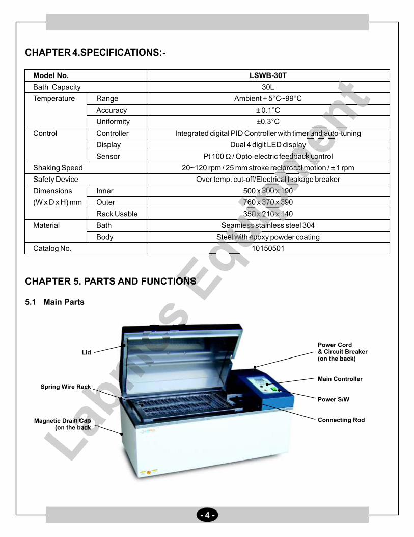
CHAPTER 4.SPECIFICATIONS:-
Model No. LSWB-30T
Bath Capacity 30L
Temperature Range Ambient + 5°C~99°C
Accuracy ± 0.1°C
Uniformity ±0.3°C
Control Controller Integrated digital PID Controller with timer and auto-tuning
Display Dual 4 digit LED display
Sensor Pt 100 Ω / Opto-electric feedback control
Shaking Speed 20~120 rpm / 25 mm stroke reciprocal motion / ± 1 rpm
Safety Device Over temp. cut-off/Electrical leakage breaker
Dimensions Inner 500 x 300 x 190
(W x D x H) mm Outer 760 x 370 x 390
Rack Usable 350 x 210 x 140
Material Bath Seamless stainless steel 304
Body Steel with epoxy powder coating
Catalog No. 10150501
CHAPTER 5. PARTS AND FUNCTIONS
5.1 Main Parts
Lid
Spring Wire Rack
Magnetic Drain Cap(on the back
Power Cord & Circuit Breaker(on the back)
Main Controller
Power S/W
Connecting Rod
24.2SV
RPM
TIME 37.0
00.00
60SV
RPM
TIME
SV
RPM
TIME
- 5 -
3 7 0200
PRESENTTEMPERATURE
SV
RPM
TIME
HeaterOn
Heat RPM
0
40
80
120MAX
SAFETY
LAMP
POWER
Timer Cool
.
ON / OFFControl
HEAT RPM COOL
MODE
AT DSP
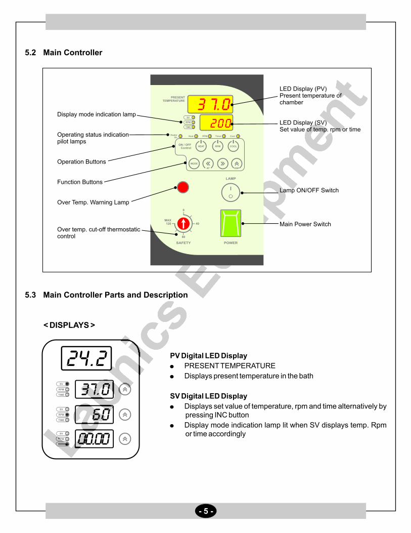
Display mode indication lamp
Operating status indication pilot lamps
Operation Buttons
Function Buttons
Over Temp. Warning Lamp
Over temp. cut-off thermostatic control
LED Display (PV)Present temperature of chamber
LED Display (SV)Set value of temp. rpm or time
Lamp ON/OFF Switch
Main Power Switch
5.2 Main Controller
5.3 Main Controller Parts and Description
< DISPLAYS >
PV Digital LED Display
PRESENT TEMPERATURE
Displays present temperature in the bath
SV Digital LED Display
Displays set value of temperature, rpm and time alternatively by pressing INC button
Display mode indication lamp lit when SV displays temp. Rpm or time accordingly

- 6 -
[PILOT LAMPS]
Display Mode Indication Lamp
SV pilot lamp lit when SV LED displays set temperature
RPM pilot lamp lit when SV LED displays set rpm
TIME pilot lamp lit when SV LED displays time
Operating Status Indication Lamp
Heater On: Turned on when controller give output to heater. ON and OFF during PID control
Heat: Turned on when heating starts by pressing HEAT button
RPM: Turned on when shaking starts by pressing RPM button
TIMER: Turned on when user set wait-off timer and timer starts count down by press HEAT or RPM button
COOL: No function on Shaking Water Bath
[OPERATION BUTTONS]
HEATER OUTPUT :
Start and stop heating (Press to ON and press again to OFF)
RPM Button
Start and stop shaking (Press to ON and press again to OFF)
COOL Button
Your shaking Water Bath has no cooling system
Button has no function
MODE Button
Press to set temp. Rpm and time
Press to set factory parameters. (See how to set factory parameters on SETTING PARAMETER section)
LEFT SHIFT Button
Press to shift cursor to left digit when setting temp. Rpm or time.
AUTO-TUNING Function
Press and hold for 5 seconds to start auto-tuning
Your Shaking Water Bath was auto-tuned before shipment
RPM
HeaterOn
Timer
Cool
Heat
SV
RPM
TIME
ON / OFFControl
HEAT RPM COOL
MODE
MODE

- 7 -
About Auto-Tuning
The temperature of your Shaking Water Bath is controlled by precise PID Microprocessor controller.
Controller automatically calculate optimum operating parameters such as P, I, A and D value.
Auto-Tuning command enables to optimize temperature control.
When Auto-Tuning needed
Your Shaking Water Bath is auto-tuned before shipment. You do not need to auto-tune again before use.
Auto-tune is necessary in case of
- Replacing heater (after replacing heater and check temperature stability. If temperature stability is ok, auto-tuning is not necessary).
- Replacing main controller (when you replace main controller, you have to auto-tune again).
How to start Auto-Tuning
- Input factory parameter as instruction.o- Set temperature at 40 C.
- Set rpm at 60 rpm.
- Press HEAT and RPM button to start temperature and rpm control.
- Press and hold LEFT SHIFT BUTTON for 5 seconds.
- LED displays blink indicating auto-tuning is stars with beep sound.
- Wait for 1 ~ 2 hours to finish auto-tuning.
- LED displays stop blinking with beep sound indicating auto-tuning is finished.
- Shaking Water Bath is auto-tuned again and ready to use.
RIGHT SHIFT Button
Press to shift cursor to right digit when setting temp. Rpm or time.
INC Button
Increase values by 1 increment.
DSP Function
In normal display mode, press INC button to change display on SV LED display to shoe set temp. Rpm or time alternatively.

- 8 -
SAFETY LAMP/OVER-TEMP. CUT-OFF SAFETY THERMOSTAT
Safety lamp turned on indicating current bath temperature is higher than over temp. Cut-off setting.
Turn over temp, cut-off safety thermostat to 20% higher than normal operating temperature.
o(Ex. Your operating temperature is 40 C, set safety thermostat o o
at 60 C, if bath temperature increase higher than 60 C by any reason, thermostat automatically cut-off heater and lamp is turned on).
POWER SWITCH
Main Power Switch.
CHAPTER 6. OPERATION:-
Before Operation:-
1) Check electrical requirement on the name plate before connect to consent.
2) Place your Shaking Water Bath on the flat and level surface.
3) Remove packing material in the bath.
4) Make sure to place shaking wire rack on the right position.
5) Connect power plug in rear panel to wall mount receptacle.
Getting Started:-
1) Pour water into the bath. Do not fill water over 60~70% of bath height.
2) Be careful not to be over flow during shaking motion.
3) Using deionized water is highly recommended.
4) Turn the circuit breaker on located on the back. Turn the POWER switch on. The PV LED READOUT displays current temperature of the bath.
0
40
80
120MAX
POWER

- 9 -
Setting Temperature, RPM and Time:-You can change operating temperature, rpm and time by using MODE button.
Setting mode changes as left figure.
Setting Temperature:-
1) Press MODE button to set temperature in normal display mode.
2) PV Digital LED displays "TEMP" and SV Digital LED displays current SV temperature and prompt user input.
3) Press SHIFT button to move left or right digit.
4) Press INC button to increase or decrease value.
5) Temperature can be set from ambient +5°C to 99.9°C
6) Press MODE button again to go RPM setting.
7) Press MODE button twice to go normal display mode.
(Illus. showed how to change operating temperature from o o37.0 C to 40.0 C).
24.2
TEMP
TACH60.0
24.2
TIME00.00
24.2
TEMP
TEMP40.0

- 10 -
Setting RPM:-
1) Press MODE button twice to set RPM in normal display mode.
2) PV Digital LED displays " TACH " and SV Digital LED displays current SV RPM and prompt user input.
3) Press SHIFT button to move left or right digit.
4) Press INC button to increase or decrease value.
5) RPM can be set from 20 ~ 120 rpm.
6) Press MODE button again to go TIMER setting.
7) Press MODE button to go normal display mode.
(Illus showed how to change operating RPM from 60 to 30).
Maximum operating RPM may less than specification When sample is loaded in the shaking basket. RPM may affected by weight of load or other operating Conditions.
Error Message (Err0)
If motor cannot be start within 15 seconds after pressing RPM button, controller warning error by audio visual message. Controller displays ERR0 and keep beep sound.
Press RPM button to escape from error status.
Trouble Shooting
Check any obstacle which may obstruct shaking motion.
Check total weight of sample loaded in the basket shouldn't exceed than maximum load (less than 15 kg).
Check basket is well positioned to move back and forth.
Setting Timer:-
1) Press MODE button three times to set timer in normal display mode.
2) PV Digital LED displays "TIME" and SV Digital LED displays current time and prompt user input.
3) Press SHIFT button to move left or right digit.
4) Press INC button to increase or decrease value.
5) For continuous operation set time at 00.00.
6) Timer can be set from 1 Min to 99 Hr 59 Min.
7) Press MODE button to go normal display mode.
(Illus. showed how to change operating time from continuous to 1 Hr).
Time scale can be changed in min: sec.
Refer factory parameter setting to change time scale.
24.2
TACH
TACH30
60
24.2
TIME
TIME01.00
00.00
- 11 -
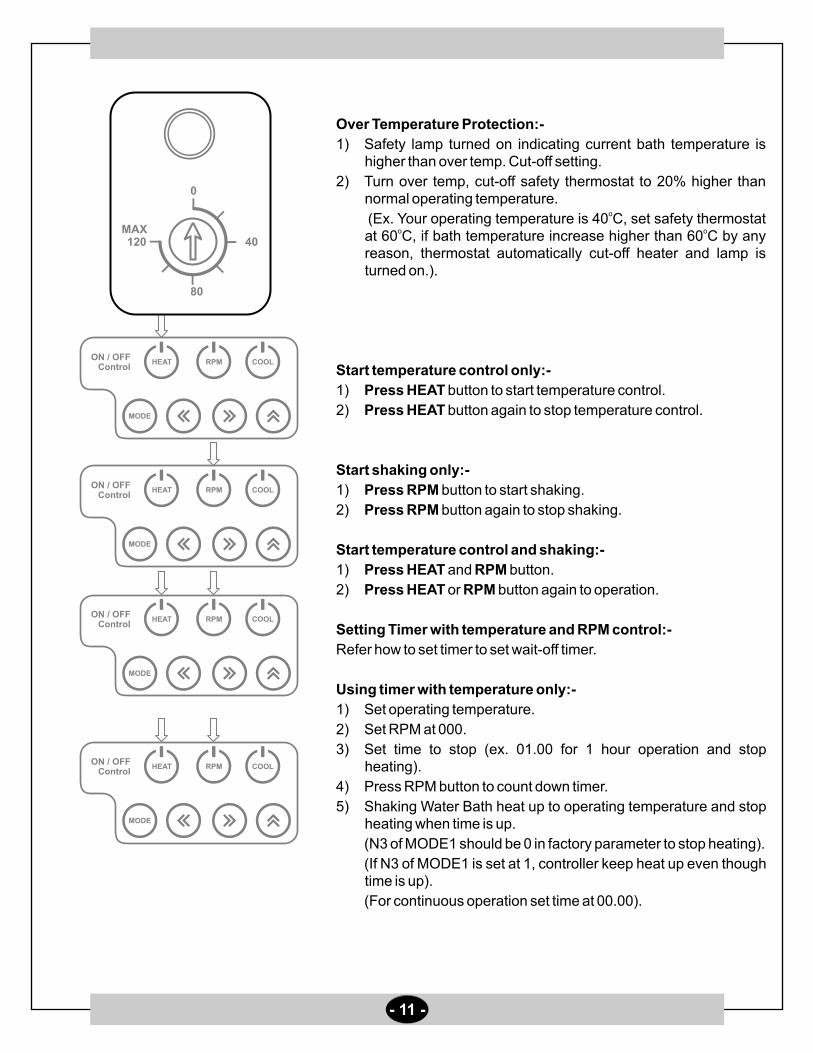
Over Temperature Protection:-
1) Safety lamp turned on indicating current bath temperature is higher than over temp. Cut-off setting.
2) Turn over temp, cut-off safety thermostat to 20% higher than normal operating temperature.
o (Ex. Your operating temperature is 40 C, set safety thermostat o o
at 60 C, if bath temperature increase higher than 60 C by any reason, thermostat automatically cut-off heater and lamp is turned on.).
Start temperature control only:-
1) Press HEAT button to start temperature control.
2) Press HEAT button again to stop temperature control.
Start shaking only:-
1) Press RPM button to start shaking.
2) Press RPM button again to stop shaking.
Start temperature control and shaking:-
1) Press HEAT and RPM button.
2) Press HEAT or RPM button again to operation.
Setting Timer with temperature and RPM control:-
Refer how to set timer to set wait-off timer.
Using timer with temperature only:-
1) Set operating temperature.
2) Set RPM at 000.
3) Set time to stop (ex. 01.00 for 1 hour operation and stop heating).
4) Press RPM button to count down timer.
5) Shaking Water Bath heat up to operating temperature and stop heating when time is up.
(N3 of MODE1 should be 0 in factory parameter to stop heating).
(If N3 of MODE1 is set at 1, controller keep heat up even though time is up).
(For continuous operation set time at 00.00).
0
40
80
120MAX
ON / OFFControl
HEAT RPM COOL
MODE
ON / OFFControl
HEAT RPM COOL
MODE
ON / OFFControl
HEAT RPM COOL
MODE
ON / OFFControl
HEAT RPM COOL
MODE

- 12 -
Using timer with RPM only
1) Set operating temperature below present temperature.
2) Set RPM you want to operate.
3) Set time to stop (ex. 01.00 for 1 hour operation and stop shaking).
4) Press RPM button to count down timer.
5) Shaking Water Bath start shaking and stop when time is up.
(For continuous operation set time at 00.00).
Using timer with temperature and RPM
OPERATING MODE A: Keep operating temperature and stop shaking only when time is up.
(Set N3 of MODE 1 at 1)
1) Set operating temperature.
2) Set RPM.
3) Set time to stop (ex. 01.00 for 1 hour operation and stop heating).
4) Press HEAT button and press RPM button to start count down timer.
5) Shaking Water Bath heat up and start shaking.
6) When time is up, shaking stops and temperature keep at set temperature.
(N3 of MODE1 should be 1 in factory parameter to keep heating).
OPERATING MODE B: Stop temperature and shaking control when time is up.
(Set N3 of MODE 1 at 0)
1) Set operating temperature.
2) Set RPM.
3) Set time to stop (ex. 01.00 for 1 hour operation and stop heating).
4) Press HEAT button and press RPM button to start count down timer.
5) Shaking Water Bath heat up and start shaking.
6) When time is up, temperature control and shaking stops.
(N3 of MODE1 should be 0 in factory parameter to keep heating).
CHAPTER 7.FREQUENTLY ASKED QUESTION
7.1 Temperature keep increasing and decreasing under operating temperature
Cause: SAFETY setting is lower than operating temperature
Solution: Turn SAFETY setting clockwise higher than operating temperature
Cause : Alternation of optimum factory parameters
Solution: Auto-tune again

- 13 -
7.2 Temperature Overshoot
Cause : High room temperatureo
Solution: Your Shaking Water Bath has no cooling system. If room temperature is higher than 30 C, your bath ocannot maintain less than 35.0 C. Use water bath in optimum operating condition
Cause: Heat generated by reaction or insulation
Solution: Open lid during operation so that water in the bath lose heat to ambient air
7.3 LED displays uuuu and beep
oCause: Over heat higher than 100 C. check water levelo o
Solution: Your water bath cannot be used over 100 C. If temperature increase over 101 C, controller warning high temperature and cut-off heater
CHAPTER 8. TROUBLE SHOOTING
Error Symbol Cause Solutiono
uuuu Over heat higher than 100 C Call for Service
nnnn Sensor disconnection Call for Service
ErrO Motor failure or shaking disable Remove obstacle
Lessen weight load
Check motor
CHAPTER 9. SETTING FACTORY PARAMETERS:-
Factory Parameter A
To set factory parameter A,
press and hold MODE Button for 5 seconds
Press SHIFT and INC Button to change values
Press MODE Button to go next parameter
To escape from Parameter mode to normal display mode, press and hold MODE Button for 6 seconds.
Parameter Name of Parameter Setting Range Factory Default User Set Value
Symbol and Descriptions
BEEP BEEP ON TIME 0 ~ 99 SEC 30
Beep on time in seconds after timer is over.
If the value is set at 0, continuously beep until press RPM button

- 15 -
Adj Temperature Adjustment - 99.9 ~ 299.9 Calibrated value
Compensate temperature deviation
If the actual temperature measured by standard thermometer is different from temperature
which controller read, user can compensate temperature difference by Adj function
Ex) Actual temp = 100.0 Displayed temp = 99.9 Set Adj at 0.1
Actual temp = 99.5 Displayed temp = 100.0 Set Adj at - 0.5
COOL COOLER ON TEMP. - 99.9 ~ T-Lt value 35 No function
SET Temp. > Cool value -> Cooler relay off
SET Temp. < Cool value -> Cooler relay on
ALH ALARM LIMIT HIGH 00.0 ~ 99.9 0.2 No function
No function
ALL ALARM LIMIT LOW 00.0 ~ 99.9 0.3 No function
No function
USLP Speed increment per second 1 ~ 59 RPM 5 Do Not Change
Acceleration and deceleration rate when start up and stop shaking
For smooth start-up and stop motion, keep this value high
HYS HYSTERESIS 0.2 No function
No function
Frpm Fix rpm speed display 0 ~ 99 5
Fix displayed operating RPM within a range. Control rpm drift
Dloc LOCK PASSWORD 0000, 1111 0000
Protect set values and parameters from unauthorized change
N3 N2 N1 N0
Available value to set 0 or 1 0 or 1 0 or 1 0 or 1
Where N3 : KEY LOCK 1 : LOCK 0 : UNLOCK
N2 : RESERVED 1 : 0 :
N1 : PARAMETER DATA LOCK 1 : LOCK 0 : UNLOCK
N0 : SET VALUE DATA LOCK 1 : LOCK 0 : UNLOCK
N3 (KEY LOCK): Protect pressing button.
N1 (PARAMETER DATA LOCK) : Protect parameter values stored in the controller
N0 (SET VALUE DATA LOCK) : Protect user set values such as temperature and time

- 16 -
Mode2 OPERATING MODE CONTROL 0000~1111 1000
N3 N2 N1 N0
Available value to set 0 or 1 0 or 1 0 or 1 0 or 1
Where N3 : DECIMAL PLACE DISPLAY 1 : YES (0.1oC) 0 : NO (1oC)
N2 : ALARM HIGH DATA TYPE 1 : ABSOLUTE 0 : RELATIVE
N1 : ALARM LOW DATA TYPE 1 : ABSOLUTE 0 : RELATIVE
N0 : HEATER OUTPUT CONTROL WHEN DOOR OPEN
1 : HEATER ON 0 : HEATER OFF
Mode3 OPERATING MODE CONTROL 0000 0000
N3 N2 N1 N0
Available value to set 0 or 1 0 or 1 0 or 1 0 or 1
Where N3 : RESERVED
N2 : RESERVED
N1 : ALH 1 : START RELAY OFF 0 : START RELAY ON
N0 : RESERVED
Cton Defrost cycle time in minutes No function
CtoF Defrost duration time in minutes No function
Cdly Delay time of compressor start No function
DrAn Fix drift of temperature display within the set value 0.5
Temperature drifts during operation owing to several reasons.
To eliminate temperature drift, set DrAn value to fix temp. within the value
dton Fix drift of temperature display within the set value during defrost No function
- 17 -
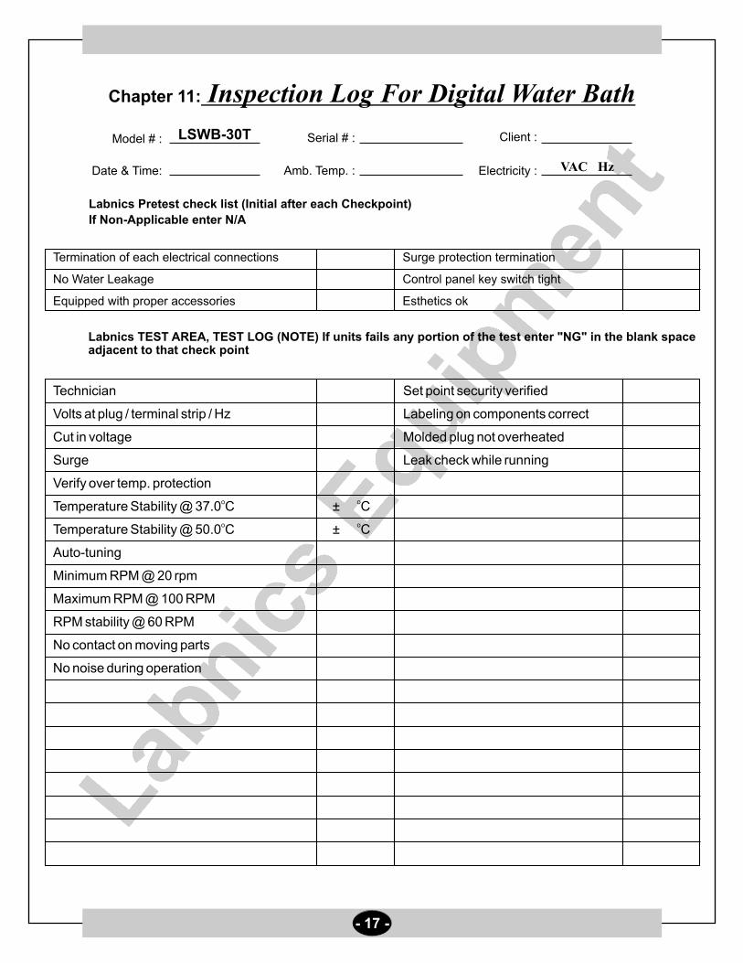
Chapter 11: Inspection Log For Digital Water Bath
Model # : Serial # :
Date & Time: Amb. Temp. :
Labnics Pretest check list (Initial after each Checkpoint)
If Non-Applicable enter N/A
Termination of each electrical connections
No Water Leakage
Equipped with proper accessories
LSWB-30T
Labnics TEST AREA, TEST LOG (NOTE) If units fails any portion of the test enter "NG" in the blank space adjacent to that check point
Client :
Electricity :
Surge protection termination
Control panel key switch tight
Esthetics ok
VAC Hz
Technician Set point security verified
Volts at plug / terminal strip / Hz Labeling on components correct
Cut in voltage Molded plug not overheated
Surge Leak check while running
Verify over temp. protectiono oTemperature Stability @ 37.0 C ± Co o
Temperature Stability @ 50.0 C ± C
Auto-tuning
Minimum RPM @ 20 rpm
Maximum RPM @ 100 RPM
RPM stability @ 60 RPM
No contact on moving parts
No noise during operation

Customer’s Address :
SERVICE REPORT
Contact Person / Designation :
Tel.No.:
Fax No.:
Weekly Off.:
Dept.:
Date
Nature of Problem :
Observation & Action Taken :
Customer’s Remarks :
Parts Replaced :
Parts Recommended / Action Required : Yes
Service Engineer’s Name & Signature
Requisition Number :
Customer’s Name, Signature, Date & Stamp
Page ____ Of ____
No
Model Serial No.Date :
Status : OK
Installation
Demonstration
Maintenance
Repairs
Application
Calibration
Validation
Not OK
Warranty
Contract
Billable
Courtesy
SR. No.SystemConfiguration
Time
From To
- 18 -

Labnics Equipment43040 Christy St., Fremont, CA 94538 USA.Toll Free : (877) 620 9992Tel. : (925) 271 4322Fax : (925) 886 0400Email : [email protected] : www.labnics.com