Embed Size (px)
Citation preview
Shaking Table Testing of a Multi-Storey Post-tensioned Timber
Building equipped with Advanced Damping System
PONZO F.C.+, DI CESARE A., SIMONETTI M., NIGRO D. University of Basilicata
V.le Ateneo Lucano, 10 – 85100 Potenza, ITALY
+ [email protected] http://www2.unibas.it/ponzo/Sito/MAIN.html
SMITH T., PAMPANIN S. University of Canterbury,
Christchurch NEW ZEALAND
CARRADINE D. Branz,
Wellington NEW ZEALAND
Abstract: - This paper describes the main results of shaking table testing performed on a post-tensioned timber
frame building equipped with an advanced damping system. This experimental campaign, carried out in the
structural laboratory of the University of Basilicata in Potenza, Italy, is part of a series of experimental tests in
collaboration with the University of Canterbury in Christchurch, New Zealand. The specimen is 3-dimensional,
3-storey, 2/3rd scale and is made by using post-tensioned timber frames in both directions. During the testing
programme, the specimen was tested both with and without the addition of dissipative steel angle reinforcing
which was designed to yield at a certain level of drift. These steel angles release energy through hysteresis
during seismic loading, thus increasing damping. This paper discusses the main results of the experimental
testing and presents comparisons with numerical outcomes using two non-linear finite element codes: SAP2000
and RUAUMOKO.
Key-Words: - Shaking table test, Timber Buildings, Damping system, Post-Tensioning, Passive control, Steel dissipating devices, Pres-Lam technology.
1 Introduction This paper describes the main results of shaking
table testing performed on a multi-storey post-
tensioned timber frame building equipped with an
advanced damping system. The study evaluates the
feasibility of applying jointed ductile post-
tensioning technology, originally conceived for use
in concrete structure [11], to glue laminated timber
(glulam). The aim of the project is to evaluate the
seismic performance of the system and further
develop the system for use in multi-storey timber
frame buildings. The post-tensioned timber concept
(under the name PRES-LAM) has been developed at
the University of Canterbury and extensively tested
in the structural laboratory of the university [6, 12].
This technology enables the design of buildings
having large bay lengths (8-12m), reduced structural
sections and lower foundation loads with respect to
traditional construction methods. The PRES-LAM
concept uses post-tensioning technology in order to
connect structural timber elements. The structural
response of a post-tensioned timber frame centres
on the moment-rotation response of its connections.
In order to design all structural characteristics a
certain starting point must be selected as the design
drift (θd). From this point all of the elastic
contributions of the frame must be subtracted (beam
rotation, column rotation, joint panel rotation,
interface rotation). Having obtained the rotation to
be imposed at the beam-column joint the Modified
Monolithic Beam Analysis (MMBA) method is used
in order to calculate the moment capacity of the
Advances in Mathematics and Statistical Sciences
ISBN: 978-1-61804-275-0 308
rocking joint. From this, the required value of initial
post-tensioning and steel reinforcing can be defined
and the key to this type of system is made up of the
ratio β between the moment resistance provided by
the post-tensioning and the moment resistance
provided by the dissipation (Fig 1).
Fig. 1. Moment response with varying levels of the parameter β
Although a simple concept, this ratio provides the
cornerstone in the understanding of system
performance. Clearly, during design this choice
affects both damping and moment capacity of the
system and therefore changing this value will have a
direct effect on both capacity and demand. In Stage
One of PRES-LAM project a full-scale beam-
column joint was designed, fabricated, constructed
and tested at the Structural Laboratory of UNIBAS.
This experimental programme was completed
midway through 2011 providing excellent results
[13] and began to answer key questions regarding
system performance. During testing the application
of the post-tensioned timber concept to glulam
timber was confirmed and the system displayed the
same excellent performance under static loading as
when the system was employed with laminated
veneer lumber (LVL). In the current stage of the
project a 3-dimensional, 3-storey timber structure
(Figg. 2 and 3) has been dynamically tested in real
time in the UNIBAS lab. During the experimental
campaign the size of the structural members,
building layout and mass was not altered, however
different values of post-tensioning and steel
reinforcing moment capacity contributions were
investigated. The dissipative devices used were
based on yielding steel angles which activate at low
drift levels, both increasing the moment capacity of
the system and adding energy dissipation (thus
reducing seismic load through damping) without
inducing plastic deformations in other elements.
This paper will describe briefly the detailing, the
testing set-up of the experimental model and the
testing results with and without dissipation. Finally,
comparisons between experimental outcomes and
SAP2000 and RUAUMOKO numerical predictions
will be also shown.
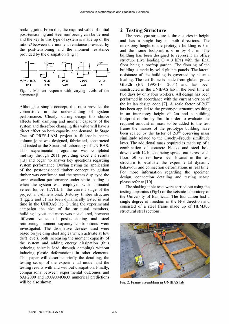
2 Testing Structure The prototype structure is three stories in height
and has a single bay in both directions. The
interstorey height of the prototype building is 3 m
and the frame footprint is 6 m by 4.5 m. The
building has been designed to represent an office
structure (live loading Q = 3 kPa) with the final
floor being a rooftop garden. The flooring of the
building is made by solid glulam panels. The lateral
resistance of the building is governed by seismic
loading. The test frame is made from glulam grade
GL32h (EN 1995-1-1 2004) and has been
constructed in the UNIBAS lab in the brief time of
two days by only four workers. All design has been
performed in accordance with the current version of
the Italian design code [7]. A scale factor of 2/3rd
has been applied to the prototype structure resulting
in an interstorey height of 2m and a building
footprint of 4m by 3m. In order to evaluate the
required amount of mass to be added to the test
frame the masses of the prototype building have
been scaled by the factor of 2/3rd observing mass
similitude related to the Cauchy-Froude similitude
laws. The additional mass required is made up of a
combination of concrete blocks and steel hold
downs with 12 blocks being spread out across each
floor. 50 sensors have been located in the test
structure to evaluate the experimental dynamic
behaviour and connection deformations in real time.
For more information regarding the specimen
design, connection detailing and testing set-up
please refer to [10].
The shaking table tests were carried out using the
testing apparatus (Fig4) of the seismic laboratory of
the University of Basilicata. The foundation had a
single degree of freedom in the N-S direction and
consisted of a steel frame made up of HEM300
structural steel sections.
Fig. 2. Frame assembling in UNIBAS lab
Advances in Mathematics and Statistical Sciences
ISBN: 978-1-61804-275-0 309

Fig. 3. Experimental model built in UNIBAS lab
Fig. 4. Shaking foundation in UNIBAS lab.
The foundation was driven by an MTS 244.41
dynamic actuator characterized by a capacity of ±
500 kN and ± 250 mm stroke. The actuator was
fixed to a hinge at the base of the foundation and
pushed against the 6 m thick strong wall used during
the beam-column test programme. Pressure for the
actuator was provided by 3 MTS SilentfloTM 505-
180 hydraulic pumps. The foundation was situated
upon 4 SKF frictionless sliders (model LLR HC 65
LA T1) with one each situated under the four
columns. These sliders sat upon a series of levelling
plates set upon grout-pads to ensure that a system
with a coefficient of friction of less than 1% was
obtained. The table was displacement controlled and
therefore seismic input was supplied as table
displacement over a specific time interval.
2.1 Energy dissipating devices During dynamic testing energy dissipation devices
have been added to the structure in order to add
strength and damping and reduce displacements
without increasing of accelerations or base shears.
This passive hysteretic devices are made by yielding
steel angles and have been located in beam-column
and column-foundation connections (Fig. 5).
Fig. 5. Details of beam-column and column-foundation connections.
The dissipative system is based on the DIS-CAM
system [3] developed at the University of Basilicata
in Potenza, Italy and consists of the use of low
carbon steel angles designed to yield in a controlled
manner. These angles not only provide dissipative
capacity (thus reducing demand) but also
significantly contribute to capacity. An extended
experimental campaign has been performed at
UNIBAS in order to define the angle forms to be
used in the dynamic experimental model. Following
this two different methods of creating a
concentrated yield area were selected both based on
the concept of creating a controlled zone of
concentrated yielding. The first option (taken from a
section of square hollow section tube) involves the
removal of two holes and the second of these
involves the milling down of a certain section of an
equal steel and. Milled steel angle ID5 configuration
Advances in Mathematics and Statistical Sciences
ISBN: 978-1-61804-275-0 310

has been chosen for dynamic testing with
dissipation adopting the angled cut as particular
form of transition. This type of transition proved to
be successful and simple and is now recommended
for all milled angle manufacture.
For more information regarding the experimental
campaign, please refer to [1].
Fig. 6. Steel angles device for beam-column joint selected for dynamic testing (with dissipation) and experimental Force-Displacement device characterisation.
2.1 Seismic Input The testing input was a set of 7 spectra compatible
earthquakes selected from the European strong-
motion database (Fig. 7).
0
10
20
30
0 1 2 3Tsc (sec)
Sa (m/sec2
) 196
535*1.5
1228*1.5
Average
Code Spectrum
Fig. 7. Spectral characteristics of selected earthquakes and comparison with the Code Spectrum considered
Seismic loading during testing has been mono-
directional applied along the north-south axis of the
building. The seismic intensities were progressively
increased until the design performance criterion was
achieved. The code spectrum was defined in
accordance with the current Eurocode for seismic
design (EN 1998-1:2003 2003) having a PGA of
ag= 0.35 and a soil factor of S = 1.25 (Soil class B –
medium soil) giving a PGA for the design spectrum
of ag= 0.4375. The elastic response spectra of three
accelerograms used in blind numerical predictions
SAP 2000 and RUAUMOKO are shown below with
their Average and Code Spectrum.
3 Numerical modelling From the conception of the post-tensioned jointed
ductile connection it has been clear that the nature
of the controlled rocking mechanism lent itself well
to the use of a lumped plasticity approach in
modelling.
This approach combines the use of elastic
elements with springs, which represent plastic
rotations in the system. Recent studies have also
recognized the importance of modelling and
accounting for the elastic joint rotation in the
calculation of rocking connection rotation, therefore
a rotational spring was added in the joint panel
region.
Fig. 8. Numerical model of the test frame, beam-column joint and column/foundation interface.
This procedure can be applied to the design of a
timber hybrid connection provided a few simple
considerations are made. This method of modelling
has been used in the predictive modelling of the
structural behaviour under the planned input
loading. The specimen was modelled (Fig. 8)
considering rotational springs to predict the moment
rotation response and the effects of dissipation of
0 5 10 15 20 25
Displacement (mm)
-25
-20
-15
-10
-5
0
5
10
15
20
25
30
35
Fo
rce
(k
N)
ID5 A
ID5 B
Advances in Mathematics and Statistical Sciences
ISBN: 978-1-61804-275-0 311
the post-tensioned beam-column joints and a multi-
spring column/foundation interface to match the
structural rocking movement. Rotational springs
have been calibrated against the design procedure
for the moment calculation of a hybrid joint
presented in Appendix B of the New Zealand Code
for the Design of Concrete Structures [8]. Post-
tensioning was represented using tri-linear elastic
elements for both models with bounded Ramberg-
Osgood and Buoc-Wen rotational spring models
used to represent the steel dissipative angles in the
RUAUMOKO and SAP2000 model respectively
[2].
3 Shaking Table Tests In the first series of tests, carried out on July 2013,
the structure was first tested with the addition of the
dissipative reinforcing angles. Upon completion the
angles were removed and testing without dissipation
was performed.
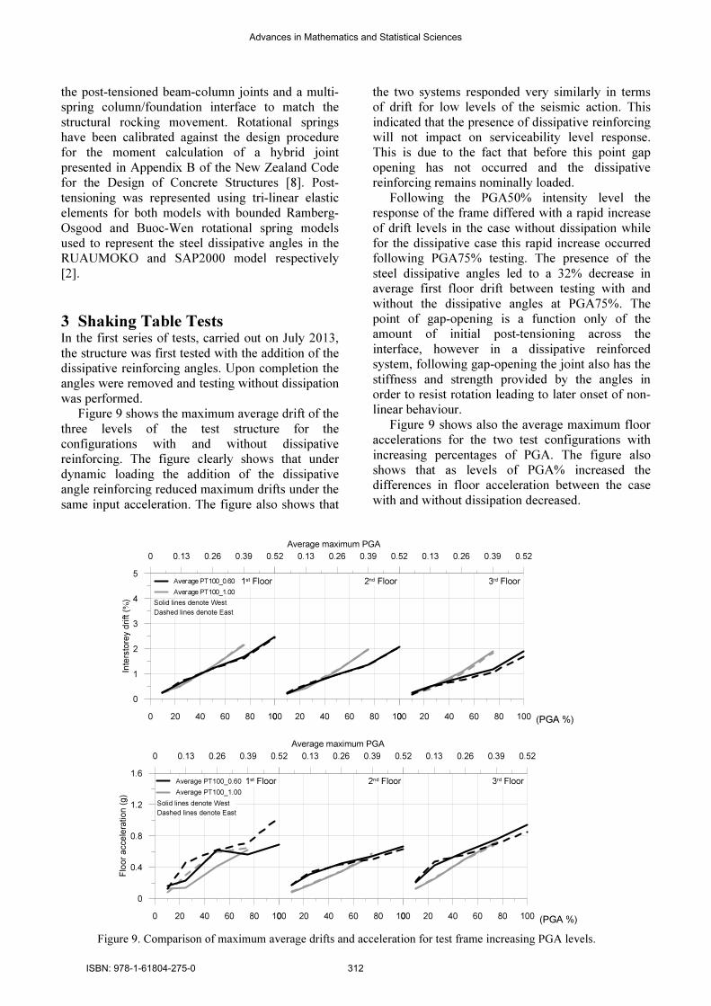
Figure 9 shows the maximum average drift of the
three levels of the test structure for the
configurations with and without dissipative
reinforcing. The figure clearly shows that under
dynamic loading the addition of the dissipative
angle reinforcing reduced maximum drifts under the
same input acceleration. The figure also shows that
the two systems responded very similarly in terms
of drift for low levels of the seismic action. This
indicated that the presence of dissipative reinforcing
will not impact on serviceability level response.
This is due to the fact that before this point gap
opening has not occurred and the dissipative
reinforcing remains nominally loaded.
Following the PGA50% intensity level the
response of the frame differed with a rapid increase
of drift levels in the case without dissipation while
for the dissipative case this rapid increase occurred
following PGA75% testing. The presence of the
steel dissipative angles led to a 32% decrease in
average first floor drift between testing with and
without the dissipative angles at PGA75%. The
point of gap-opening is a function only of the
amount of initial post-tensioning across the
interface, however in a dissipative reinforced
system, following gap-opening the joint also has the
stiffness and strength provided by the angles in
order to resist rotation leading to later onset of non-
linear behaviour.
Figure 9 shows also the average maximum floor
accelerations for the two test configurations with
increasing percentages of PGA. The figure also
shows that as levels of PGA% increased the
differences in floor acceleration between the case
with and without dissipation decreased.
0 20 40 60 80 100
0
1
2
3
4
5
Inte
rsto
rey d
rift (%
)
Average PT100_0.60
Average PT100_1.00
0 20 40 60 80 1000 20 40 60 80 100
1st Floor 2nd Floor 3rd Floor
Solid lines denote West
Dashed lines denote East
0 0.13 0.26 0.39 0.520 0.13 0.26 0.39 0.52
Average maximum PGA
0 0.13 0.26 0.39 0.52
(PGA %)
0 20 40 60 80 100
0
0.4
0.8
1.2
1.6
Flo
or
accele
ration (
g)
Average PT100_0.60
Average PT100_1.00
0 20 40 60 80 1000 20 40 60 80 100
1st Floor 2nd Floor 3rd Floor
Solid lines denote West
Dashed lines denote East
0 0.13 0.26 0.39 0.520 0.13 0.26 0.39 0.52
Average maximum PGA
0 0.13 0.26 0.39 0.52
(PGA %)
Figure 9. Comparison of maximum average drifts and acceleration for test frame increasing PGA levels.
Advances in Mathematics and Statistical Sciences
ISBN: 978-1-61804-275-0 312

For low levels of PGA% a slight increase in floor
acceleration is observed. It is likely that this was due
to the increased stiffness of the structure before the
initial slipping of the floors and the failure of the
column base connection. These two factors led to a
reduced building stiffness as evidenced by a higher
building period. The base shear response of the
structure with and without dissipative reinforcing is
also shown in Figure 10. This was calculated using
the accelerations and the model masses. Although a
load cell was placed on the dynamic actuator these
readings included the weight of the shaking
foundation and provided higher values than what
was actually present during testing. As expected the
base shear display the same general trend as the
accelerations presented above. A maximum average
value of 97 kN was recorded for testing case with
dissipation corresponding to 100% of PGA intensity
which was similar to the design level base shear.
0 20 40 60 80 100Percentage PGA
0
40
80
120
160
Ba
se s
hea
r (V
b, kN
)
000196x
000535y
001228x
Average
a)
0 20 40 60 80 100Percentage PGA
0
40
80
120
160
Ba
se
sh
ea
r (V
b,
kN
)
000535y
000196x
001228x
Average
b)
Fig. 10. Maximum base shear of test frame at increasing levels of PGA for a) with and b) without dissipation testing
Although it was not possible to directly compare
this value to the design values and assuming a linear
trend to continue, a value of approximately 91 kN
(similar to the performance point) could be obtained
also for testing case without dissipation.
During the first series of testing, carried out on
2013, some slipping of the dissipative connection
was observed. This reduced the effectiveness of the
reinforcing by decreasing both stiffness and
dissipative capacity. Although the slipping shown is
approximately 3 mm this represented almost half of
the expected reinforcing displacement and was 6
times the yielding displacement. It is likely that this
fact led or at least was a contributing factor to the
increased drifts and displacements. Slipping
between the base of the dissipative reinforcing and
the connection plate also explains why the
dissipative loops were low in spite of the significant
levels of gap opening. It is unclear the degree to
which this slipping occurred during testing with
only one of the connections being recorded. In any
case, despite this anomaly, the system demonstrated
its overall effectiveness and thus its robustness.
The final study of the dynamic test results
involves the evaluation of the elastic and inelastic
damping of the frame. During a seismic event the
presence of damping reduces demand on a structure.
The total equivalent viscous damping of a structure
(ξ) is made up of two sources: the elastic (ξel) and
the hysteretic damping (ξhyst). Damping values are
evaluated and compared in this section.
Elastic damping is used to introduce damping not
captured by the hysteretic model represented by the
codified reduction methods. Many methods can be
used in order to evaluate the elastic damping of a
building. During the analysis of the test structure,
the half-power bandwidth (HPB) method [4] was
used. This method estimates the damping using the
frequency range, in combination with a Welch
Fourier analysis [14]. The HPB method returns
significant results in the analysis of a stationary
system (i.e. no significant non-linear response)
therefore it has been applied using the forced
vibration hammer identification testing. In the
application of the HPB method, firstly, the
amplitude of each (in this case the first) natural
frequency is obtained. Values of ξel = 1.49% and
1.84% were calculated for tests with and without
dissipation respectively.
Test configuration without reinforcing showed
slightly elevated elastic damping likely due to the
reduction in stiffness created by the series testing
with dissipation. It is important to note however that
an experimental model is without many of the
sources of elastic damping present in a normal
structure (partitions, cladding etc.).Values were
therefore expected to be lower than in a real post-
tensioned timber structure which contains these
elements.
Advances in Mathematics and Statistical Sciences
ISBN: 978-1-61804-275-0 313
As with elastic damping, several methods are
available to evaluate inelastic damping [5]. The
evaluation of hysteretic damping (ξhyst) during
dynamic testing is complicated by the forced nature
of the system response. In order to have hysteretic
damping gap opening and dissipative reinforcing,
yield must occur. With increased displacement
beyond yield (i.e. increased ductility) the equivalent
viscous damping of a post-tensioned timber
structure also increases. During seismic response
therefore, damping increases with stronger ground
motion. Test without dissipation did not contain the
use of dissipative reinforcing at the beam-column
joint indicating that the timber system itself is
capable of providing nominal amounts of hysteretic
dissipation during strong motions [9]. The total
response of the system without dissipation was very
similar to the response of model with dissipation
(ξhyst=2.8% for PGA75%) tending to indicate that
the damping characteristics of the two
configurations are very similar. This is not
unexpected as the dissipative reinforcing will only
provide damping during the maximum frame
response cycle of which few occur during the total
frames responses. It can be seen that only one clear
flag shaped hysteretic loop occurred during all tests.
Performing the area EQV analysis method
suggested by [5], the equivalent viscous damping
value of this loop was ξhyst = 7.8 %.
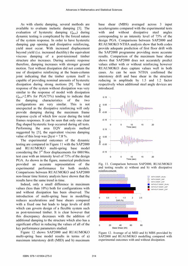
The experimental outcomes of the dynamic
testing are compared in Figure 11 with the SAP2000
and RUAUMOKO multi-spring base model
considering the 3rd floor displacements for 000196x
test case with an intensity level of 75% of the design
PGA. As shown in the figure, numerical predictions
provided an accurate representation of the
experimental performance for both models.
Comparisons between RUAUMOKO and SAP2000
non-linear time history analysis have shown that the
results have the same trend in time.
Indeed, only a small difference in maximum
values (less than 10%) both for configurations with
and without dissipation has been observed. The
introduction of multi-spring base in modelling
reduces accelerations and base shears compared
with a fixed one but leads to large levels of drift
which can govern design of a flexible system such
as post-tensioned timber. It is clear however that
this discrepancy decreases with the addition of
additional damping to the structure which also has a
significant effect in reducing the values of all of the
key performance parameters studied.
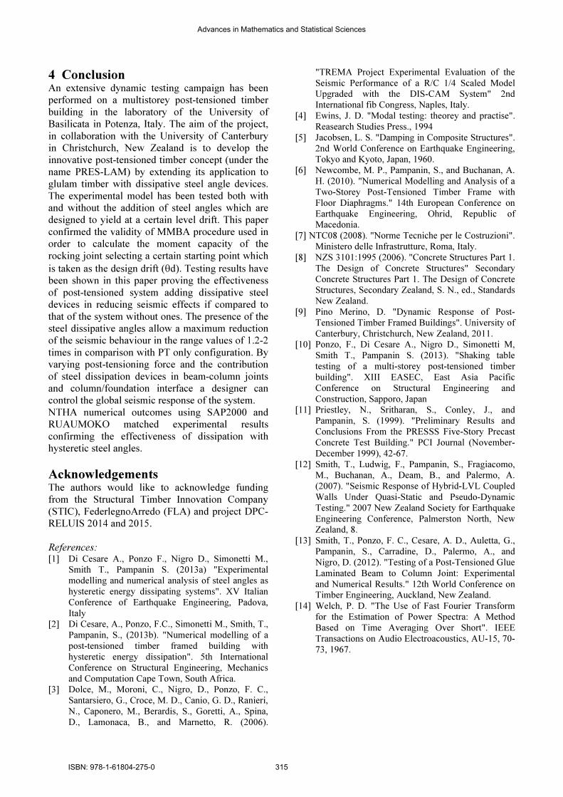
Figure 12 shows SAP2000 and RUAUMOKO
multi-spring base model results in terms of a)
maximum interstorey drift (MID) and b) maximum
base shear (MBS) averaged across 3 input
accelerograms compared with the experimental tests
with and without dissipative steel angles
corresponding to an intensity level of 75% of the
design PGA. Comparisons between SAP2000 and
RUAUMOKO NTHA analysis show that both codes
provide adequate prediction of first floor drift with
the SAP2000 programme providing more accurate
results. Comparison of the maximum base shear
shows that SAP2000 does not accurately predict
values either with or without reinforcing however
RUAUMOKO does capture values well in both
cases. As can be seen NTHA confirmed the
interstorey drift and base shear in the structure
reducing in amplitude by 1.5 and 1.2 factor
respectively when additional steel angle devices are
introduced.
0 5 10 15 20Time (sec)
-0.15
-0.05
0.05
0.15D
isp
l. (
m)
0 5 10 15 20Time (sec)
-0.15
-0.05
0.05
0.15
Dis
pl. (
m)
Fig. 11. Comparison between SAP2000, RUAUMOKO and testing results a) without and b) with dissipative reinforcement.
0 0.5 1 1.5 2 2.5
Drift (%)
0 20 40 60 80
Base Shear (kN)
Figure 12. Average of a) MID and b) MBS provided by SAP2000 and RUAUMOKO modelling compared with experimental outcomes with and without dissipation.
WITH DISSIP._RUAU
WITH DISSIP._SAP
WITH DISSIP._EXP
WITHOUT DISSIP._RUAU
WITHOUT DISSIP._SAP
WITHOUT DISSIP._EXP
Advances in Mathematics and Statistical Sciences
ISBN: 978-1-61804-275-0 314
4 Conclusion An extensive dynamic testing campaign has been
performed on a multistorey post-tensioned timber
building in the laboratory of the University of
Basilicata in Potenza, Italy. The aim of the project,
in collaboration with the University of Canterbury
in Christchurch, New Zealand is to develop the
innovative post-tensioned timber concept (under the
name PRES-LAM) by extending its application to
glulam timber with dissipative steel angle devices.
The experimental model has been tested both with
and without the addition of steel angles which are
designed to yield at a certain level drift. This paper
confirmed the validity of MMBA procedure used in
order to calculate the moment capacity of the
rocking joint selecting a certain starting point which
is taken as the design drift (θd). Testing results have
been shown in this paper proving the effectiveness
of post-tensioned system adding dissipative steel
devices in reducing seismic effects if compared to
that of the system without ones. The presence of the
steel dissipative angles allow a maximum reduction
of the seismic behaviour in the range values of 1.2-2
times in comparison with PT only configuration. By
varying post-tensioning force and the contribution
of steel dissipation devices in beam-column joints
and column/foundation interface a designer can
control the global seismic response of the system.
NTHA numerical outcomes using SAP2000 and
RUAUMOKO matched experimental results
confirming the effectiveness of dissipation with
hysteretic steel angles.
Acknowledgements The authors would like to acknowledge funding
from the Structural Timber Innovation Company
(STIC), FederlegnoArredo (FLA) and project DPC-
RELUIS 2014 and 2015.
References: [1] Di Cesare A., Ponzo F., Nigro D., Simonetti M.,
Smith T., Pampanin S. (2013a) "Experimental
modelling and numerical analysis of steel angles as
hysteretic energy dissipating systems". XV Italian
Conference of Earthquake Engineering, Padova,
Italy
[2] Di Cesare, A., Ponzo, F.C., Simonetti M., Smith, T.,
Pampanin, S., (2013b). "Numerical modelling of a
post-tensioned timber framed building with
hysteretic energy dissipation". 5th International
Conference on Structural Engineering, Mechanics
and Computation Cape Town, South Africa.
[3] Dolce, M., Moroni, C., Nigro, D., Ponzo, F. C.,
Santarsiero, G., Croce, M. D., Canio, G. D., Ranieri,
N., Caponero, M., Berardis, S., Goretti, A., Spina,
D., Lamonaca, B., and Marnetto, R. (2006).
"TREMA Project Experimental Evaluation of the
Seismic Performance of a R/C 1/4 Scaled Model
Upgraded with the DIS-CAM System" 2nd
International fib Congress, Naples, Italy.
[4] Ewins, J. D. "Modal testing: theorey and practise".
Reasearch Studies Press., 1994
[5] Jacobsen, L. S. "Damping in Composite Structures".
2nd World Conference on Earthquake Engineering,
Tokyo and Kyoto, Japan, 1960.
[6] Newcombe, M. P., Pampanin, S., and Buchanan, A.
H. (2010). "Numerical Modelling and Analysis of a
Two-Storey Post-Tensioned Timber Frame with
Floor Diaphragms." 14th European Conference on
Earthquake Engineering, Ohrid, Republic of
Macedonia.
[7] NTC08 (2008). "Norme Tecniche per le Costruzioni".
Ministero delle Infrastrutture, Roma, Italy.
[8] NZS 3101:1995 (2006). "Concrete Structures Part 1.
The Design of Concrete Structures" Secondary
Concrete Structures Part 1. The Design of Concrete
Structures, Secondary Zealand, S. N., ed., Standards
New Zealand.
[9] Pino Merino, D. "Dynamic Response of Post-
Tensioned Timber Framed Buildings". University of
Canterbury, Christchurch, New Zealand, 2011.
[10] Ponzo, F., Di Cesare A., Nigro D., Simonetti M,
Smith T., Pampanin S. (2013). "Shaking table
testing of a multi-storey post-tensioned timber
building". XIII EASEC, East Asia Pacific
Conference on Structural Engineering and
Construction, Sapporo, Japan
[11] Priestley, N., Sritharan, S., Conley, J., and
Pampanin, S. (1999). "Preliminary Results and
Conclusions From the PRESSS Five-Story Precast
Concrete Test Building." PCI Journal (November-
December 1999), 42-67.
[12] Smith, T., Ludwig, F., Pampanin, S., Fragiacomo,
M., Buchanan, A., Deam, B., and Palermo, A.
(2007). "Seismic Response of Hybrid-LVL Coupled
Walls Under Quasi-Static and Pseudo-Dynamic
Testing." 2007 New Zealand Society for Earthquake
Engineering Conference, Palmerston North, New
Zealand, 8.
[13] Smith, T., Ponzo, F. C., Cesare, A. D., Auletta, G.,
Pampanin, S., Carradine, D., Palermo, A., and
Nigro, D. (2012). "Testing of a Post-Tensioned Glue
Laminated Beam to Column Joint: Experimental
and Numerical Results." 12th World Conference on
Timber Engineering, Auckland, New Zealand.
[14] Welch, P. D. "The Use of Fast Fourier Transform
for the Estimation of Power Spectra: A Method
Based on Time Averaging Over Short". IEEE
Transactions on Audio Electroacoustics, AU-15, 70-
73, 1967.
Advances in Mathematics and Statistical Sciences
ISBN: 978-1-61804-275-0 315