Embed Size (px)
Citation preview

NUMBER ELEVEN NOTES FROM THE SHOP
SHAKER DESIGN THREE TABLES AT HOME YESTERDAY OR TODAY
WOODSMITH 1

Wood Ismitl h Number Eleven September, 1980
Editor
Donald B. Peschke
Art Director
Ted Kralicek
Contributing Editor
Adolph E. Peschke
Subscription Manager
Linda Hill
Talking Shop
WOODSMITH^ (ISSN 0164-4114) is published
bimonthly (February, April, June, August,
October, December) by Woodsmith Publishing
Co., 2200 Grand Ave., Des Moines, Iowa 50312. WOODSMITH$ is a registered trademark of the
Woodsmith Publishing Co. ©Copyright 1980 by Woodsmith Publishing Co.
All Rights Reserved.
Printed in U.S.A. 0894
THE SHAKERS
The Shaker sect had its origins in the English Quaker church. Though the two sects shared quite similar religious views, they should not be confused as the same. The Shakers (or Shaking Quakers as they were called early on) were actually a splinter society of the Quakers in England.
In the year 1785 Ann Lee joined this society. Some fourteen years later, while in prison, Ann Lee experienced some remarkable visions and was acknow¬ ledged the spiritual Mother of the new sect.
She, and a small band of followers, set sail for America, and in 1776 founded the first Shaker settlement in Niskeyuna, New York. Over the next seven years, until she died in 1784, Ann Lee toured parts of New England, making converts to the Shaker faith and establishing communities.
During the first half of the 1800’s the total membership steadily grew, as did the number of communal settlements. These communities were established as self-sustaining havens apart from the world around them.
Among the converts were a good number of craftsmen — cabinetmakers, wood turners, carpenters, etc. — whose skills and dedicated work were much needed to supply these communities with chairs, tables, candlestands, case goods, and all necessary furniture.
As would be expected, the Shaker’s religious views permeated every aspect of their society — including their approach to the design and building of furniture. Today, as we look at the products of Shaker craftsmen, it’s all too easy to think only in negative terms. Certainly they held a prejudice against “vain show” and “unnecessary elaboration.”
As their religion found its way to the woodworking shops, all intricate carvings, veneers, inlays, and extrav¬ agant turnings (common features of “worldly” furniture of that period) were eliminated from Shaker design. The Shaker workmen produced practical furniture. Utility, not decoration, was their goal.
However, early examples of Shaker furniture took this ideal of unen¬ cumbered simplicity to an extreme. The result was clumsy, almost crude, furniture.
But gradually, Shaker craftsmen developed a certain style and design. Their dedication to quality workmanship
led them to the basics of good design. Quiet elegance. Simple, yet graceful. Delicate, though sturdy. One hundred years later we would attribute these terms to “modern” furniture (especially that of Europe and, in particular, Denmark).
The Shakers achieved a rare charm in their furniture designs. A basic, enduring quality that strikes a chord in all of us. It is furniture that deserves to be built — carefully and quietly in our shops. And, when a piece is finished, it seems to remind us, “possess this as though you possessed it not.”
NOTES AND THOUGHTS
THREE TABLES. In this issue are designs for three Shaker-style tables. None of these tables can rightfully be called a reproduction because I was working from photographs, not the actual table. However, I have tried to be true to the Shaker approach to design ... in attitude, if not actual dimensions.
All of these tables are built from solid cherry. I know cherry is expensive, and sometimes beyond the budget for the shop. But if you’re used to working only with softwoods, you’ll quickly discover why cherry is so highly praised as a furniture wood. It works beautifully, whether you choose power equipment or hand tools. Indeed, you’ll probably find yourself (as I did) dusting off your hand tools and getting back to some old- fashioned woodworking.
ART DIRECTOR. Ted Kralicek started work here just in time to tackle all of the artwork in this issue. I think it’s a vast improvement over what has appeared in the past, and Ted promises me it will get even better.
Ted is also anxious to start designing and building furniture and projects for future issues (as soon as I unchain him from his art board).
One last thing, we’ve decided to give a free subscription to anyone who can pronounce Peschke/Kralicek three times in one breath.
UPDATE. In Woodsmith No. Ten I reviewed the Wagner Safe-T-Planer. I used the radial arm saw model to plane the top of the drop-leaf table in this issue. Once again, I highly recommend it. Two sources that now carry the Safe-T-Planer are listed below. Trendlines. Address: 375 Beacham St., Chelsea, MA 02150. Phone: (800)767-9999. Constantine’s. 2050 Eastchester Road, Bronx, NY 10461. Phone: (800) 223-8087.
2 WOODSMITH
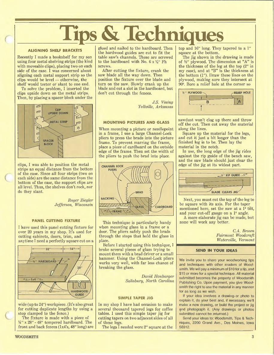
Tips & Techniques ALIGNING SHELF BRACKETS
Recently I made a bookshelf for my son using four metal shelving strips (the kind with moveable clips), placing two on each side of the case. I was concerned about aligning each metal support strip so the clips would be level — otherwise, the shelf would teeter or slant to one end.
To solve the problem, I inserted the clips upside down on the metal strips. Then, by placing a spacer block under the
clips, I was able to position the metal strips an equal distance from the bottom of the case. Since all four strips (two on each side) are the same distance from the bottom of the case, the support clips are all level. Thus, the shelves don’t rock, nor do they slant.
Roger Ziegler Jefferson, Wisconsin
PANEL CUTTING FIXTURE
I have used this panel cutting fixture for over 20 years in my shop. It's used for cutting cabinets, doors, trim, and anytime I need a perfectly square cut on a
wide (up to 24") workpiece. (It’s also great for cutting duplicate lengths by using a stop clamped to the fence.)
The fixture is made with a piece of W x 28" - 48" tempered hardboard. The front and back fences (lx4’s, 48" long) are
glued and nailed to the hardboard. Then the hardwood guides are cut to fit the table saw’s channels. These are screwed to the hardboard with No. 6 x V8" Fh screws.
After cutting the fixture, crank the saw blade all the way down. Then position the fixture over the blade and turn on the saw. Slowly crank up the blade and cut a slot in the hardboard, but don’t cut through the fences.
J.S. Vining Yellville, Arkansas
MOUNTING PICTURES AND GLASS
When mounting a picture or needlepoint in a frame, I use a large Channel-Lock pliers to press the brads into the picture frame. To prevent marring the frame, place a piece of cardboard on the outside edge of the frame. Then set the width of the pliers to push the brad into place.
This technique is particularly handy when mounting glass in a frame or a door. The pliers safely push the brads through the stops that hold the glass in place.
Before I started using this technique, I broke several pieces of glass trying to mount them with a brad driver or a small hammer. Using the Channel-Lock pliers works very well, with far less chance of breaking the glass.
David Honbarger Salisbury, North Carolina
SIMPLE TAPER JIG
In my shop I have had occasion to make several thousand tapered legs for coffee tables. I used this simple taper jig for cutting tapers on two adjacent sides of all of these legs.
The legs I needed were 2" square at the
top and 16" long. They tapered to a 1" square at the bottom.
The jig shown in the drawing is made of V6" plywood. The dimension at “A” is the thickness of the leg at the top (2" in my case), and at “B” is the thickness at the bottom (1"). Draw these lines on the plywood, making sure they intersect at 90°. Bore a relief hole at the corner so
sawdust won’t clog up there and throw off the cut. Then cut away the material along the lines.
Square up the material for the legs, and cut it just a bit longer than the finished leg is to be. Then lay the material in the notch.
In use, the long edge of the jig rides against the rip guide of the bench saw, and the saw blade should just clear the edge of the jig at its widest part.
Next, you must cut the top of the leg to be square with its axis. For the taper mentioned here, set the saw at a 1° tilt, and your cut-off gauge on a 1° angle.
A more elaborate jig can be made, but none will work any better.
C.A. Brown Fairmont Woodcraft Waterville, Vermont
SEND IN YOUR IDEAS
We invite you to share your woodworking tips
and techniques with other readers of Wood- smith. We will pay a minimum of $10 for a tip, and
$15 or more for a special technique. All material
submitted becomes the property of Woodsmith
Publishing Co. Upon payment, you give Wood- smith the right to use the material in any manner for as long as we wish.
If your idea involves a drawing-or photo to
explain it, do your best and, if necessary, we’ll
make a new drawing, or build the project or jig
^nd photograph it. (Any drawings or photos
submitted cannot be returned.)
Send your ideas to: Woodsmith, Tips & Tech¬
niques, 2200 Grand Ave., Des Moines, Iowa 50312.
WOODSMITH 3

Shaker Side Table CRISP CLEAN LINES . . . UNDERSTATED ELEGANCE
This table is a beautiful example of Shaker design at its very best. Nothing fancy, just a useful little table that would be equally at home in an 1880 household (when the original table as probably built), as well as in the decorating scheme of a contem¬ porary home.
This table was originally built by Henry Whiton of the Shaker Community in Enfield, Conn. I had only a photograph to go by when I built the table shown in the photograph to the right. It cannot rightfully be called a true reproduction because I didn’t know the actual dimensions of the table, but it is close to the original. Also, I sized this table to fit the Cutting Diagram shown here.
The entire table is made of solid cherry (except for the drawer sides and back, which are birch).
THE TAPERED LEGS
The legs on this table are Hepplewhite- style tapered legs. As shown in the Cutting Diagram, I cut the legs from a piece of 5/4 cherry. The actual thickness of 5/4 hardwood should be lW', but it is sometimes sold at YA"} which is what I used. I cut the four pieces for the legs lVi" x VA" square and 26V£" long. Once the leg blanks were squared up I cut the mortises at the top of the legs for the aprons and the rails.
I cut the mortises in the back legs first (just because they’re the easiest). As shown in Fig. la, these mortises are centered on the leg and intersect at the middle. I clamped a fence to the drill press and cut the mortises down the center with a lA” router straight bit, speed 4200 rpm. The technique is similar to that shown in Woodsmith No. Eight for cutting a slot mortise. The only caution in cutting these mortises is to set the depth of cut at only Vi" to Vie" with each pass.
The front legs present a bit more of a problem. I cut the two small mortises for the front rails first — for a haunched tenon at the top and for a four-shouldered tenon below. The mortise for the side apron is positioned so it does not intersect with the rail mortises.
Note: All of these mortises were stopped short of the full width of the apron or rail. (The dimensions of the mortises are shown in Figs, la and lb.) This ensures that no part of the mortise would inadvertently extend beyond the shoulders of the tenons. In other words, a cover-up.
MATERIALS LIST CUTTING DIAGRAM
A Legs 1 Ve x 1 Vb - 26!4
B Aprons 3/4 x 5 - 133/e
C Rails % X3/4 -13
D Drawer Guides % x3/4 - 12
E Top 3/4 x 16-18
F Stop as needed
G Drawer Front Va x3Vi - 12 H Drawer Sides fe x3'/2 -11% 1 Drawer Back x 314 - 12
THREE
BOARDS
% x 516 ONE
BOARD
*/. x 516
After the mortises were cut, I tapered the legs at b/i6" per foot or 116°, starting 6" down from the top, and ending so the bottom is %" square. (See page 11 for cutting tapered legs.) The tapers are cut on the two inside faces of the legs (the faces with the mortises). The two outside faces are left straight.
THE APRONS AND RAILS
The next step is to cut the aprons and rails to approximate length, allowing enough length for the tenons. The critical
measurement is the shoulder to shoulder distance, which is 12" on all five pieces. I added l3/8" ("/is" for each tenon) to the length of the aprons, and 1" (W for each tenon) to the length of the rails.
The tenons were cut on a table saw, as shown in Woodsmith No. Eight. The tenons that intersect at the back legs are initially cut the full depth of the mortise, and then mitered so they join at the center, as shown in Fig. 3b. Finally, extra shoulder cuts are made (Fig. 2), and the tenons are rounded to fit the mortises.
4 WOODSMITH

The top rail has a haunched tenon at each end. Since the mortise for this tenon stops ll/i6" down from the top, a third shoulder (Vie” deep) must be cut on the bottom edge of this tenon. The same technique is employed on the bottom rail, except two W' shoulders are cut — one on the top edge and one on the bottom edge.
At this point the aprons, rails and legs are finish sanded. (It’s much easier to do it now, than after the pieces are joined.) After sanding, I went ahead and glued up the aprons and legs with Elmer's Carpenter’s Glue.
THE DRAWER GUIDES AND DRAWER
The four drawer guides are screwed to the side aprons so they’re level with the front rails. (See cross section, Fig. 3a.) I mounted the bottom guides with three No. 8 x 114" Fh screws. However, the top rail is secured with only two screws, as shown, to allow room for the three screws that hold the top in place.
As you can see in the photo, I joined the drawer with dovetails — blind dovetails in the front and through dovetails in the back. The sides are W' birch (which gives a nice contrast to the cherry drawer front). I used Vi" Baltic birch plywood for the drawer bottom.
Unfortunately there’s not enough space in this issue to go into dovetail joinery. However, there’s no reason why you couldn’t build the drawer using a rabbet joint at the front and dadoing the back into the sides.
THE TOP
To make the top, I simply edge-glued three pieces of cherry 5V&" wide and about 19" long. After the glue was dry, I trimmed the top to the final dimensions of 16" x 18".
I wanted to use V2" cherry for the top, but I was unable to obtain it. So, I cheated a little. I used 3/4" thick stock, and then chamfered all four edges, leaving only a V2" showing. The front and back edges are cut with the blade at 8°, and the sides are cut with the blade at 19°. (These chamfers should stop !4" from the top of the legs.)
After planing and sanding the top smooth, I fastened it to the top drawer guides with No. 8 x 1 V4" Fh screws. As shown in Detail 3c, the pilot holes in the apron are bored oversize. I clamped the base to the top and bored the countersink pilot holes with a No. 8 pilot bit. Then I enlarged the holes (in the drawer guides only) to 3/i6". This way the screws have enough room to move with the top as it expands/contracts.
Finally, the table was given two coats of cherry Minwax stain, and two coats of Minwax Antique Oil Finish.
WOODSMITH 5

Candle Stand THE GRACEFUL, CURVING LINES OF A SHAKER CLASSIC
The Shakers produced an amazing variety of designs for candle stands. This one combines many of what I feel are the best attributes of Shaker design . . . especially the legs. The umbrella or spinder-foot legs form a beautiful, natural eliptical shape beneath the table. They also present some intriguing challenges. How do you cut them without wasting a lot of wood? And, how do you cut the dovetail groove and tenon to join them to the pedestal?
In keeping with tradition, I elected to build this stand of solid cherry. Though cherry is relatively expensive, I would highly recommend that you try it with this project. If the wood has to be ordered by mail, I estimate the cost would be around $25.
THE PEDESTAL
To turn the pedestal I followed the grid shown in Fig. 1. The blank for turning the base starts out as a 3 ft" x 3ft" chunk of cherry 18" long. Since cherry this thick is very difficult to find, I cut two pieces 8/4 thick (l3/4" actual) and glued them up for the blank. To ease the roughing-out stage, I bevel-ripped the corners at 45° on a table saw, leaving enough for a 3" maximum diameter.
THE DOVETAIL GROOVES
Once the base is turned, it’s simply a matter of cutting the three dovetail grooves for the legs. I must admit that it took me a while to figure out how to do this. Most designs I’ve seen for candle stands like this one show the legs dovetailed into the base, but don’t explain how to do it; or simply side-step the problem by mounting the legs to the pedestal with dowels.
But I wanted to join the legs to the pedestal with a dovetail groove and tenon. That’s the way the Shakers did it and that’s the way I wanted to do it. . . if I could only figure out how.
After much head scratching, the solution finally came to me. I made two guides and attached them to the ends of the turned pedestal. The guides provide a stable, flat-sided base so the dovetail grooves can be cut on a router table (see
Woodsmith No. Five). The guides are odd-shaped things that
begin as equilateral triangles, Fig. 3a. I drew a 3" diameter circle on a piece of scrap V2" plywood, so one edge of the circle touched the edge of the plywood. Then I added the other two sides at 60°.
MATERIALS LIST CUTTING DIAGRAM
A Pedestal 1 ft x 3 ft - 1 8*
B Legs 3/4 x 4 - 13 ft
C Cleat % x 3 -12
D Top 3/4 x!5ft -15ft**
*Two pieces glued up to 3 ft " square.
* * Three pieces glued up to 15 ft diameter.
(Note: The circle should be 3" in diameter, which is the widest diameter of the
pedestal, not the 23//' diameter at the bottom of the pedestal.)
After the triangles are cut out, the corners are trimmed off at 90°, producing three new sides that rest against the fence of the router table, Fig. 3b.
One guide is tacked to the bottom of the pedestal so it’s centered an equal distance from the original sides of the triangle, Fig. 3c. A 1" hole is drilled in the center of the other guide and it is tacked to the top
of the pedestal, Fig. 3d.
I mounted a ft" dovetail router bit in the router table and raised it to a height of just slightly more than ft". (Since the bottom part of the pedestal is actually ft" off the table, you have to raise the bit ft" to start. Then another ft" to make the 3/8"- deep dovetail groove. And, since the shoulders on both sides of the grooves are filed flat (see Fig. 5), the bit must be raised “slightly more.” Thus ... a total of slightly more than V2".)
THE LEGS
Though they look like they’d take up a lot
6 WOODSMITH
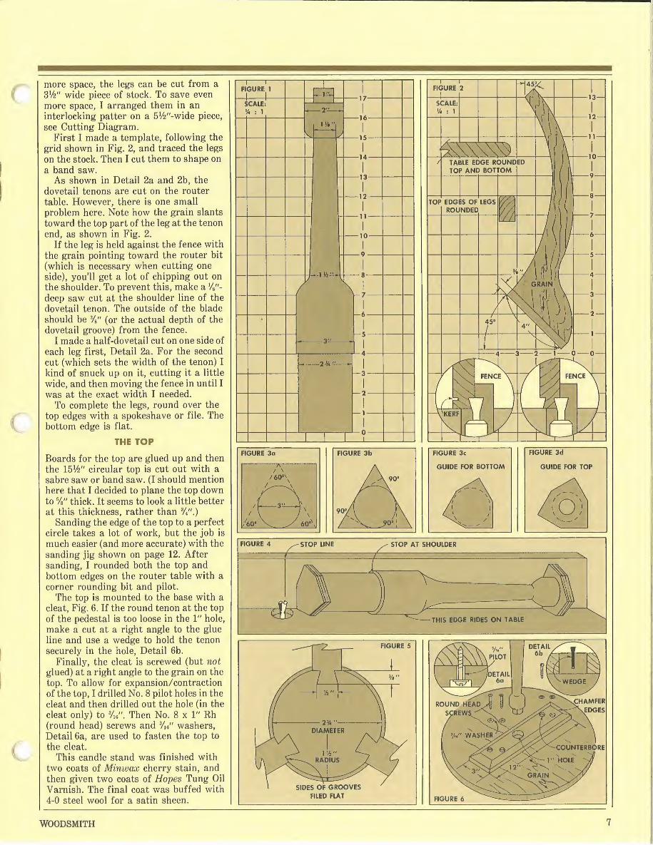
more space, the legs can be cut from a SV2" wide piece of stock. To save even more space, I arranged them in an interlocking patter on a 5Vfc"-wide piece, see Cutting Diagram.
First I made a template, following the grid shown in Fig. 2, and traced the legs on the stock. Then I cut them to shape on a band saw.
As shown in Detail 2a and 2b, the dovetail tenons are cut on the router table. However, there is one small problem here. Note how the grain slants toward the top part of the leg at the tenon end, as shown in Fig. 2.
If the leg is held against the fence with the grain pointing toward the router bit (which is necessary when cutting one side), you’ll get a lot of chipping out on the shoulder. To prevent this, make a deep saw cut at the shoulder line of the dovetail tenon. The outside of the blade should be 3/8" (or the actual depth of the dovetail groove) from the fence.
I made a half-dovetail cut on one side of each leg first, Detail 2a. For the second cut (which sets the width of the tenon) I kind of snuck up on it, cutting it a little wide, and then moving the fence in until I was at the exact width I needed.
To complete the legs, round over the top edges with a spokeshave or file. The bottom edge is flat.
THE TOP
Boards for the top are glued up and then the 15V6" circular top is cut out with a sabre saw or band saw. (I should mention here that I decided to plane the top down to Vs" thick. It seems to look a little better at this thickness, rather than %".)
Sanding the edge of the top to a perfect circle takes a lot of work, but the job is much easier (and more accurate) with the sanding jig shown on page 12. After sanding, I rounded both the top and bottom edges on the router table with a corner rounding bit and pilot.
The top is mounted to the base with a cleat, Fig. 6. If the round tenon at the top of the pedestal is too loose in the 1" hole, make a cut at a right angle to the glue line and use a wedge to hold the tenon securely in the hole, Detail 6b.
Finally, the cleat is screwed (but not glued) at a right angle to the grain on the top. To allow for expansion/contraction of the top, I drilled No. 8 pilot holes in the cleat and then drilled out the hole (in the cleat only) to 3/ie". Then No. 8 x 1" Rh (round head) screws and Vu” washers, Detail 6a, are used to fasten the top to the cleat.
This candle stand was finished with two coats of Minwox cherry stain, and then given two coats of Hopes Tung Oil Varnish. The final coat was buffed with 4-0 steel wool for a satin sheen.
WOODSMITH 7

Drop-Leaf Table IT LOOKS EASY. . . BUT IT IS CHALLENGING
It looks so easy ... deceptively easy. This Shaker drop leaf table requires quite a bit of woodworking skill. But that’s the nice thing about Shaker design — it offers a challenge without getting bogged down in intricate detail.
In all honesty, this table is more of an interpretation on Shaker design than a true reproduction. Most Shaker drop leaf tables had very narrow tops, usually only 14" to 18" wide. While this is fine for reducing the amount of floor space the table takes up, it also puts a cramp on comfort for anyone sitting at the end of the table. So, I decided to make the top wider, and thus increase the distance between the legs.
However, I did try to retain one basic tenet of the Shaker approach to furniture: the absence of molding, decorative inlays, fancy turnings, etc. In other words, the frill is gone.
Enough talk, let’s get to work. I did all of the cutting for this table on a radial arm saw. (Alternate methods using a table saw are given in parenthesis.)
THE LEGS
The legs on this table present some interesting mathmatical challenges. Each leg is tapered at 2°, then splayed out from the aprons at 3°. These angles, though slight, require a certain construction procedure.
The first step is to cut the mortises at the top of the legs. Here I decided to go with 3/8"-wide mortises in order to give the tenons a little more strength. Because the legs are splayed from the aprons at 3°, you must stop the mortises short of the bottom of the apron (and trim the tenon short also). As shown in Fig. 4b, the aprons are 3V2" wide, but the mortises are stopped at 3lA" from the top to allow for the 3° angle.
I cut these mortises on a radial arm saw by mounting a drill chuck on the accessory arbor and using a %" straight router bit, Fig. 1. (This can also be done on a drill press.)
The next step is to trim the top and bottom of the legs so these ends will be parallel to the floor when the legs are splayed. To cut the top of the leg, refer to Fig. 2. The corner between the two inside faces of the leg (those with the mortises) is placed along the line where the fence meets the table.
Swing the arm 3° to the left and tilt the head to 3° on the left scale. The blade should barely touch Corner A and take
off about Vi" from the opposite corner. (Table saw: Miter gauge is set to 3° and
the blade is tilted 3°, first contact with the blade is at Corner A.)
Make the same cut on the bottom of the leg . . . except Corner B — the one between the two outside faces (those without the mortises) — is placed along the line between the table and fence, Fig. 3. (Table saw: Corner B is the first part of the leg to make contact with the blade.)
The final step on the legs is to cut the taper. The taper starts 4" down from the top, and ends so there’s a 1" square left at the bottom. This translates to a taper of 3/8" per foot, or 2°. The tapers are cut on the two inside faces of the legs (the faces with the mortises). The two outside faces are left straight.
THE APRONS
To make the table more stable, the legs are splayed out at 3° from each apron. This is accomplished by cutting the shoulders of the aprons’ tenons at a 3° angle. So, the first step on the aprons is to cut them to approxmiate length, mitering both ends at 3°.
As shown in Fig. 4, the maximum length needed for the front and back aprons (B) is 26", and for the end aprons (C) is 17". (These measurements include the length of the tenons and allow for the
CUTTING DIAGRAM
MATERIALS LIST
A Legs 1% X P/4 -281/4
B Front & Back Aprons Va x 3 'A - 26 C End Aprons % xV/z - 17 D Leaf Support Va x 1% - 14 E Top % x21V2 -35 F Leaf % x 7 - 35 G Wedge 3/4 X 114 - 4
miters at each end.) Next the tenons are cut. I followed a
procedure similar to that shown in Woodsmith No. Eight. Briefly, the top edge of the apron is held against the fence of the radial saw with the face side (good side) up. The arm is pivoted 3° to the right (so the blade is parallel to the
8 WOODSMITH

mitered end of the apron). (Table saw: Top of the apron is against the miter gauge and gauge is pivoted to 3° on the left scale.)
Make a series of 3/i6"-deep cuts stopping at the shoulder line of the tenon (r/i6" in from the end). Then turn the apron around so the bottom edge is against the fence, and pivot the arm 3° to the left. (Table saw: To 3° on the right scale.)
When making this second cut, the important measurement is the distance between the shoulders: 231/2// along the top of the front and back aprons (B), and 141/2// along the top of the two end aprons (C), Fig. 4. (This should leave tenons lVis" long at each end.)
To complete the tenon, flip the apron over to the other side (so the “in” side is up). Make a trial cut 3/i6" deep at the end of the the tenon, and check its fit in the mortise. Finally, trim the ends of the tenon at 45°, Fig. 4a.
Clamp an apron between two legs to check the fit of the mortise and tenon joint, and to make sure the legs are angling out in the right direction.
Because the legs are splayed, there's a lot of pressure on the mortise and tenon joint. For more strength, I decided to pin these joints. (This was a common practice in Shaker furniture.) While the legs are clamped to the apron, drill %" holes through the leg and into the tenon, Fig. 4b. Later, when the legs and aprons are glued up, lA" dowel pins are driven into the holes
THE LEAF SUPPORT
There's one more step before the base is glued up: adding the leaf support (D). As shown in Fig. 7, two 30° cuts IV2" deep are made in the aprons. (These cuts are parallel to each other.)
Mark the center of the apron, and measure 7" to each side of this center mark. Make the 30° cuts at these marks.
To finish this cut, make a pocket cut by lowering the blade into the apron. You can’t make the entire cut this way (because of the angled end cuts), so it must be finished with a hand saw.
Measure this long notch and cut the leaf support (D) to fit. Now things get a little tricky. Refer to Fig. 6. Since the apron splays out at 3°, the front part of the support must be trimmed at a 3° taper so it will be parallel to the table top and leaf.
At the same time, the other end of the leaf support swings away (down) from the top. To compensate for this, a small wedge is mounted under the top. This wedge allows you to push the leaf up to a tight, level positon.
The wedges are cut from a piece of scrap at least 3V2" wide. Figure 8 shows the scrap on end on a table saw. These
WOODSMITH 9

wedges can be cut on a radial saw, but it's probably easier to cut them by hand with a back saw.
To mount the leaf support, drill a 3/8" hole through the support and about 1" into the apron. Slide a 3/8" dowel through the support, add a washer, and push the dowel into the apron. Glue the dowel into the apron only, not the leaf support.
THE TOP AND LEAVES
I tried to select and arrange the pieces for the top and leaves to form a nice grain pattern. Once chosen, I simply edge-glued them with Elmer's Carpenter’s glue.
Now it’s a matter of getting the top and both leaves exactly the same thickness. This is usually a real chore. But for this table I used the Wagner Safe-T-Planer (mentioned in Woodsmith No. Ten).
I mounted the Planer to the radial saw and ran the top and leaves under it — just barely skimming off the high spots with each pass, about V32" with each pass.
Then I finished up by sanding with a belt sander (100 grit belt), then an orbital sander, and finally by hand.
THE DROP LEAF JOINT
The final phase of construction is cutting the drop leaf joint. The technique for cutting this joint on a radial saw is discussed in the following article.
(A similar procedure is followed for cutting this joint on a table saw. This joint can also be cut on a router table.)
One method for hinging the leaf to the top is also shown in the next article. After mounting the hinges, check the fit and movement of the leaves as they are raised. Then remove the hinges for finishing.
The final step in construction is to attach the table’s top to the base. As shown in the drawing below, I did this by
boring screw pockets in the aprons. I used a No. 12 pilot bit, starting about V" from the top of the apron, and drilling at a 30° angle. The hole in the apron (only) is bored to 3/i6" and then No. 8 x 1" Fh screws are used to fasten the top in place (no glue).
I finished this table with two coats of Minwax cherry stain. Then two coats of Deft were applied to all parts of the table, and a third coat was applied to the top (for extra protection). After the final coat, I buffed the entire table with 4-0 steel wool for a nice satin sheen.
Drop Leaf CUTTING THE JOINT
Cutting a drop-leaf (or rule) joint can be difficult or very difficult. I decided to go the easy way and show the difficult method. (The two methods depend on whether the hinge is surface mounted, shown here, or mortised in.)
The first step is to plane the top and the leaves to the same thickness — somewhere between %" and V” thick. (I think ll/i6" is ideal.)
To cut the joint, start with the corner round and shoulder cut on the table’s top. Figure 1 shows this being done on a radial arm saw with a Sears molding head and a No. 2351 cutter. (On a table saw the cutter is in a vertical position.)
The alignment of this cut is critical. The relationship between the size of the shoulder and the rounded portion determines how well the completed joint functions. This cut is usually made with a Va" shoulder and a V2" corner round. I prefer a 3/i6" shoulder (as shown), leaving a V2” corner round and a W' flat portion.
The next step is to mark the outline of the corner round on to the leaf, Fig. 2. Then as you make this cove cut in the leaf (Fig. 3), sneak up on the depth of cut, just barely leaving the line you marked.
MOUNTING THE HINGES Special hinges are made for drop-leaf joints. (1Stanley makes one called a 1XA" Table Hinge, No. 46-3300.) These hinges differ from others in that the flap for the leaf is longer (l5/8") than the flap for the top (1!4"), the holes are positioned so they don’t interfere with the joint, and the countersink in the screw holes is on the “back” side — opposite side of the knuckle, Fig. lb.
If you can’t find this type of hinge, a regular IVz" x 3V2" butt hinge will work, but extra holes must be drilled in the leaf flap, Fig. la.
The position of the hinge effects the function of the joint (whether it binds or not), and determines the amount of gap between the leaf and the top when the leaf is down. To position the hinge, mark a line from the shoulder, up the edge, and along the underside of the table’s top, Fig. 2. Mount the hinge so the center of the knuckle is a tad (V32") to the leaf side of this line. This provides clearance so the joint doesn’t bind as the leaf is raised.
Chisel out a groove for the knuckle, making sure the hinge lies flat across the joint. Fasten the hinge to the top first, then to the leaf.
% )
)
10 WOODSMITH

Tapered Legs THE MATHEMATICS OF TAPERING A LEG
Hepplewhite-style furniture of the late Eighteenth Century took the tapered leg to its zenith of style and grace. A hundred years later, the Shakers removed the frill and produced furniture with crisp, clean, yet sturdy, tapered legs. Either way, tapered legs are a favorite among cabinetmakers.
Cutting tapered legs requires two things: a taper jig, and a knowledge of mathematics. The first part is easy. You can buy a taper jig (Sears has a 24" aluminum one) or make one as shown in Fig. 1.
In the design shown here, the adjusting arm (Detail lb) is raised 3/8" with a stack of washers so it will clear the saw blade when cutting l3/4" square legs. If this jig is used on a radial arm saw, the adjusting arm should extend to the right side of the jig to avoid contact with the blade.
The two marks on the top of the arms are for setting the amount of taper. Mark A, 12" from the end, is used for setting the taper in inches per foot. (For a taper of %" per foot, spread the arms lA” at Mark A.) Mark B, VA” from the end, is used for setting the taper in degrees. (For every 1° of taper spread the arms Vs" at Mark B.)
Now for the math. The box below shows the formula for determining the taper in inches per foot. For an example,
let’s say you have a table leg l3/4" square and 28" long. You want to make a taper on two adjacent sides of the leg. The taper starts 4" down from the top (to allow for the aprons), and you want to take W off the bottom of the leg (leaving a 1 lA" square).
Plugging this information in the formula: x - 12 (V6") 24". Thus, X equals .25" or lA" per foot. Set the arms XA" apart at Mark A.
To cut the taper, hold the jig firmly against the fence and move the fence (and jig) until the 4" mark on the leg (the point where the taper starts) touches the blade, Fig. 2. (On a radial saw: set the head to the “in-rip” position, and adjust the head until the blade touches the leg at the 4" mark.) Check the taper by
positioning the jig and leg as shown in Fig. 3.
When cutting the taper, I stand on the right side of the table and hold the leg against the jig with an awl. You can taper two adjacent sides this way without resetting the jig.
Now, let’s say you want to taper all four sides, taking V6" off each side and leaving a 3/4" square at the bottom. For
four-sided tapers (of equal amount) half the taper is made on two adjacent sides first, as discussed above. When cutting the remaining two sides, one of the previously tapered sides is placed against the jig, and the opposite side is cut. To do this, the spread of the arms must be doubled, and the fence is readjusted. As shown in Fig. 4, the spread of the arms is doubled to V2" per foot.
WOODSMITH 11

Sanding Circles Cutting a circle is not too difficult. But cutting a perfectly smooth circle is almost impossible. No matter how hard I try, there’s always that moment of lost concentration that causes a slight bump or shallow.
And, no matter how good the circle is, I still have to sand the edge smooth — not an easy task. About half the circumference of the circle is end grain — enough to tire even the strongest arm. That’s when this circle sanding jig comes in handy.
The jig is a relatively simple thing. It consists of a 8" square mounting plate that pivots on a 1x4 base, see Fig. 1. The key to making this jig work is to align the center of the circle to be sanded with the
center of the mounting plate. This is done with two sets of lines — one on the plate, and one on the circle.
Before attaching the plate to the base, draw two lines that intersect at the exact center of the plate. Extend these lines up the edges on all four sides. Then attach the plate to the 1x4 base. This is done with a No. 8 x 1" Rh screw and a Vie" washer (Fig. 1), so the base can revolve.
Go ahead and cut the circle, but be sure to clearly mark the center point. Then, after the circle is cut, draw two lines through the center of the circle and at right angles to each other.
Align the circle on the square plate by matching the two sets of lines, Fig. 2. Then drill pilot holes for the 3/4" Fh screws
that hold the circle to the plate. Clamp the jig to the edge of a radial
arm saw table, Fig. 3. Now, before turning on the motor, pull the sanding disk up to the circle to find the high and low spots. Start with the disk set to a high spot and slowly turn the circular workpiece in a clockwise rotation.
It helps to have a third hand gently move the sanding disk into the circle while your other two hands hold and turn the circle.
A regular sanding disk does a pretty good job. For better results, I use a Sears jointer/sanding disk. This disk is designed so only a portion of the face is in contact with the wood — thus producing a straight-line sanding pattern.
12 WOODSMITH