Embed Size (px)
Citation preview

Shai Kaspi
Technion - March 2015
Observational Astrophysics in the visible light

Optical Telescopes• Telescope - an instrument that aids in the observation of
remote objects by collecting electromagnetic radiation. From Greek: tele "far" and skopein "to look or see“.
• The first optical (visible light) telescope is attribute to be built in the Netherlands in 1608 build of two lenses.
• Galileo Galilei pointed the telescope to the sky in 1609 and recorded his findings.
• In 1668 Isaac Newton designed the first refractor telescope made with mirrors.

Three main telescope types
Refracting telescope

Galileo Telescope
• Objective:
Diameter = 3.7 cm
Focal length = 98 cm
Thickness = 2 mm
• Ocular:
Diameter = 2.2 cm
Focal length = 4.75 cm
Thickness = 1.8 mm


Optical Aberrations
• Departure of the performance of an optical system from the predictions of geometrical optics.
• Occurs when light from one point of an object after transmission through the system does not converge into a single point.
• Aberration leads to blurring of the image produced by an image-forming optical system.

Monochromatic aberration
• Are caused by the geometry of the lens and occur both when light is reflected and when it is refracted.
• Spherical aberration – due to spherical surface of the system.
• Coma aberration – point sources are distorted to have tail due to their off axis position.

Chromatic aberrations• Are caused by dispersion, the variation of a
lens's refractive index with wavelength. They do not appear when monochromatic light is used.
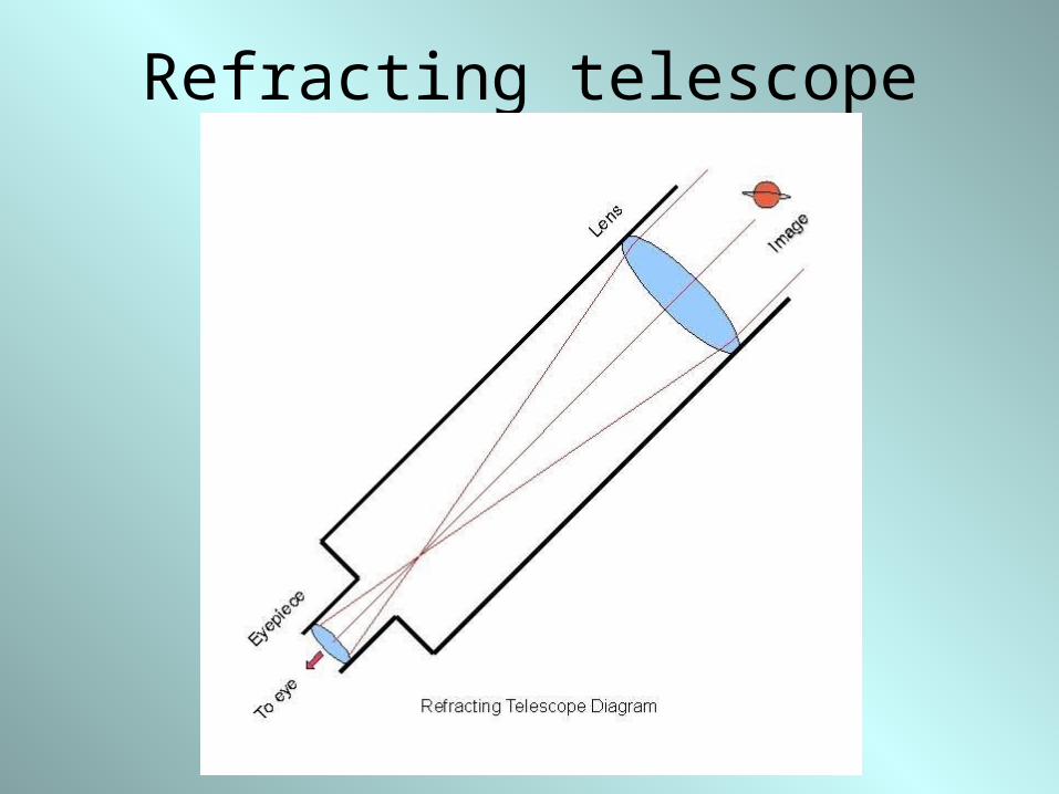
Catadioptric Telescope Schmidt camera Schmidt–Cassegrain telescope

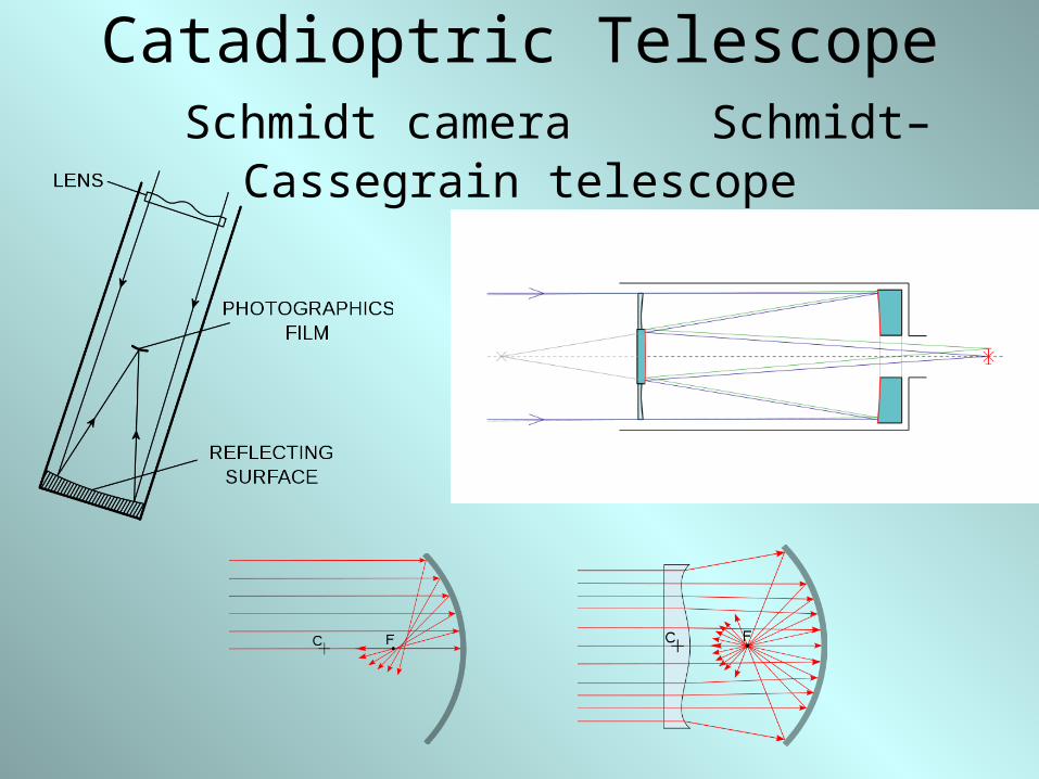
Liquid mirror telescope• Made with a reflective liquid. The most common
liquid used is mercury, but other liquids will work as well (for example, low melting alloys of gallium). The container for the liquid is rotating so that the liquid assumes a paraboloidal shape.

Angular Resolutionthe minimum distance between distinguishable
objects in an image.
Caused by airy diffraction.
θ ~ sin θ = 1.22 λ / D
θ is the angular resolution in radians.
λ is the wavelength of light.
D is the aperture diameter.

Light gathering power• For a telescope with eye piece one can use
the square of the diameters ratio of the objective of the telescope to the eye’s pupil as the light gathering power.
(Do / Dp )2

Image Scale• The number millimeters at the focal plane of
an object with an angular size of 1 radian.
• Plate Scale = 1/fo (fo is the effective focal length of the telescope in millimeters)
• Translating the radian to arcseconds one gets:
• Plate Scale = 206264.8/fo in arcsec/mm
• The number of arcseconds per pixels of a specific detector.

Field of View
• Angular area of sky that is visible through an eyepiece or can be recorded on a detector, expressed in angular diameter.
• Determined by the diameter of the eyepiece aperture or the detector - D.
• θ = D/fo in radians
• f o– effective focal length.

Angular Magnification
• The ratio of the angle of the object seen through the telescope divided by the angle of the object without the aid of the telescope
• M = fo /fe
• fo = effective focal length of the telescope
• fe = the focal length of the eye piece.
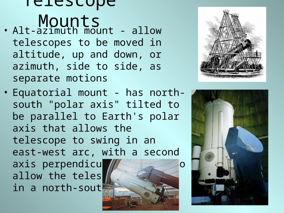
Telescope Mounts• Alt-azimuth mount - allow telescopes
to be moved in altitude, up and down, or azimuth, side to side, as separate motions
• Equatorial mount - has north-south "polar axis" tilted to be parallel to Earth's polar axis that allows the telescope to swing in an east-west arc, with a second axis perpendicular to that to allow the telescope to swing in a north-south arc
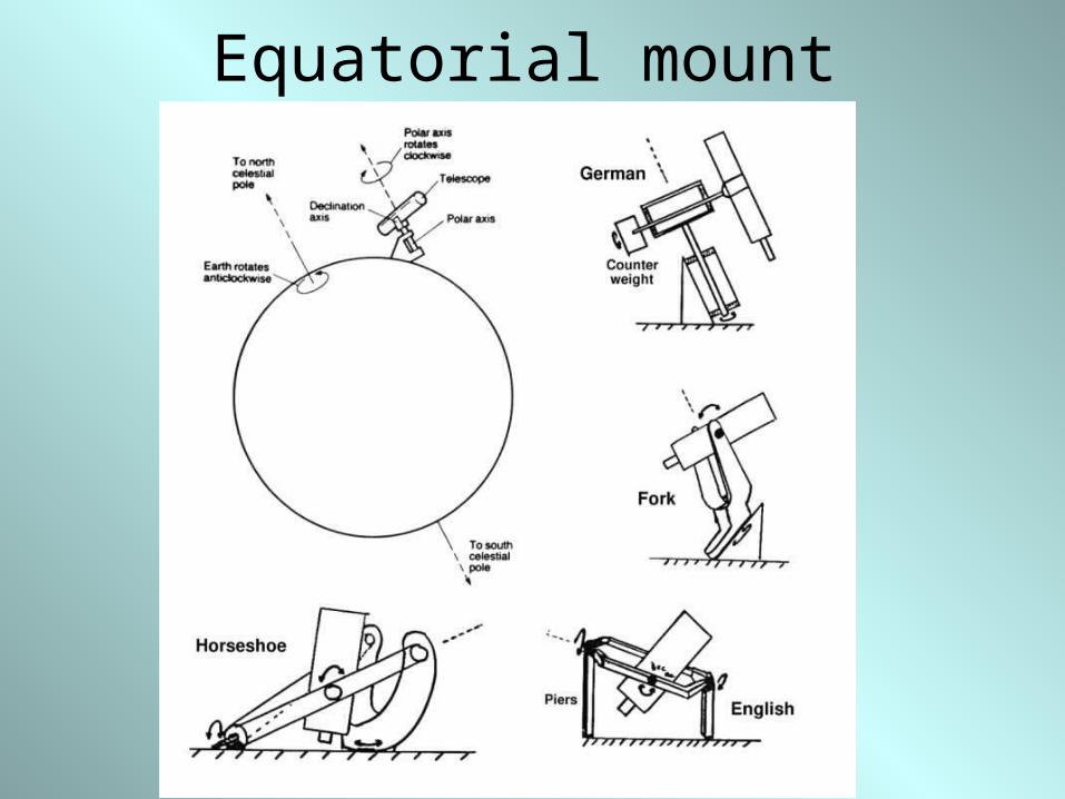
Equatorial mount

Guiding the Telescope• Equatorial mounts have a motor in the RA
axis that is tracking the moving skies.
• To make fine tracking we use a guiding star and move the telescope accordingly

Telescope mirrors• 4-5 meters mirrors
• Largest single mirror telescopes are 8.2 meter (Subaru, VLT, Gemini).
• Segmented telescopes
(Keck, HET, SALT

Mirror coating
• Mirrors traditionally are made of a thick block of glass polished to have the desired surface.
• The surface is coated using aluminum in a vacuum ion chamber.

Telescope housing

Seeing
• The blurring of astronomical objects such as stars caused by turbulent mixing in the Earth's atmosphere varying the optical refractive index.
• one of the biggest problems
for Earth-based astronomy
• Measured as Full Width
Half Maximum (FWHM) of
a point source.

Air mass• The optical path length through Earth’s
atmosphere for light from a celestial source
• light is attenuated by scattering and absorption in the atmosphere.
• Airmass ~ 1/cos(zenith-distance)


Detectors
• Human eye was the first detector when looking at the skies.
• But, the eye respond to the rate of photons from the source and weak sources cannot be detected, as well as not able to record the signal.
• Using integrating detectors one can use long exposure time to see the weak sources as well as to record the signal.

Photographic Plates
• First integrating detectors were photographic plates with black and white emulsion.
• Emulsion is not linear in respond to light.
• Emulsion has relatively low sensitivity to light (about 2-3 % efficiency, with up to 10% with special treatment).
• Photoelectric detectors like Photomultipliers and photodiodes were used for some time.
Charge Coupled Device (CCD)
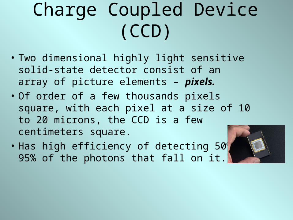
• Two dimensional highly light sensitive solid-state detector consist of an array of picture elements – pixels.
• Of order of a few thousands pixels square, with each pixel at a size of 10 to 20 microns, the CCD is a few centimeters square.
• Has high efficiency of detecting 50% to 95% of the photons that fall on it.

Quantum efficiency comparison

Array of buckets

Operation mode• The charge accumulated in each pixel is read out as a tiny
electric current.
• The current is amplified and converted (using an analog-to-digital convertor) into Analog Data Unit – ADU or “count”.
• Each “count” represent a number of photoelectrons – this number is the GAIN.
• The counts in each pixel are stored in binary mode to a certain numerical precision.
• If a pixel value can be a 16-bit binary number then the value is ranging from 0 to 65535 (= 216 – 1)
• A number above that gives saturation.

Front illuminated CCD• CCD is a matrix of a layered semiconductors.
• Each pixel is constructed with a light sensitive layer at the front, conductive layer in the middle, and the registering layer at the back.
• The active matrix on its front surface and simplifies manufacturing.
• The matrix and its wiring, however, reflect some of the light, and thus the registering layer can only receive the remainder of the incoming light; the reflection reduces the signal that is available to be captured.
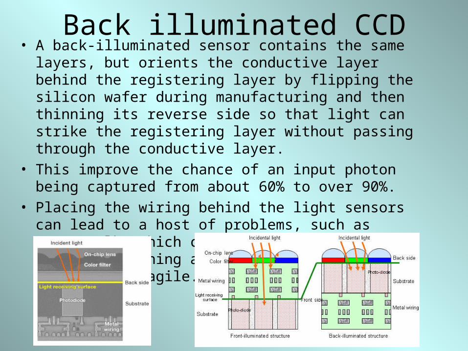
Back illuminated CCD• A back-illuminated sensor contains the same layers, but
orients the conductive layer behind the registering layer by flipping the silicon wafer during manufacturing and then thinning its reverse side so that light can strike the registering layer without passing through the conductive layer.
• This improve the chance of an input photon being captured from about 60% to over 90%.
• Placing the wiring behind the light sensors can lead to a host of problems, such as cross-talk, which causes noise and dark current. Thinning also makes the silicon wafer more fragile.

Quantum efficiency
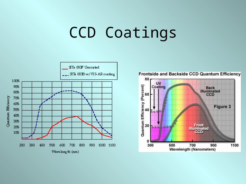
CCD Coatings

Frame Transfer CCD• have a parallel
register that is divided into two separate and identical areas, termed the Image and Storage arrays.
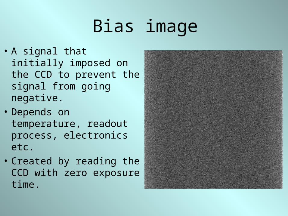
Bias image• A signal that initially
imposed on the CCD to prevent the signal from going negative.
• Depends on temperature, readout process, electronics etc.
• Created by reading the CCD with zero exposure time.

Overscan area• Virtual pixels created after the image is read
and indicate how the electronics responds to a real zero signal.

Dark image• Dark current created due to
thermal motion of electrons in the CCD.
• Minimized by cooling the CCD.• Obtained by taking exposures
with the shutter closed.• CCD are
cooled.

Flat Field image• Pixel sensitivity to light is different due to
pixel response, dust, vignetting
• Taken with uniformly illuminating the telescope’s aperture (twilight sky).
•

Object image• Exposure of the CCD to the night sky
through the telescope.
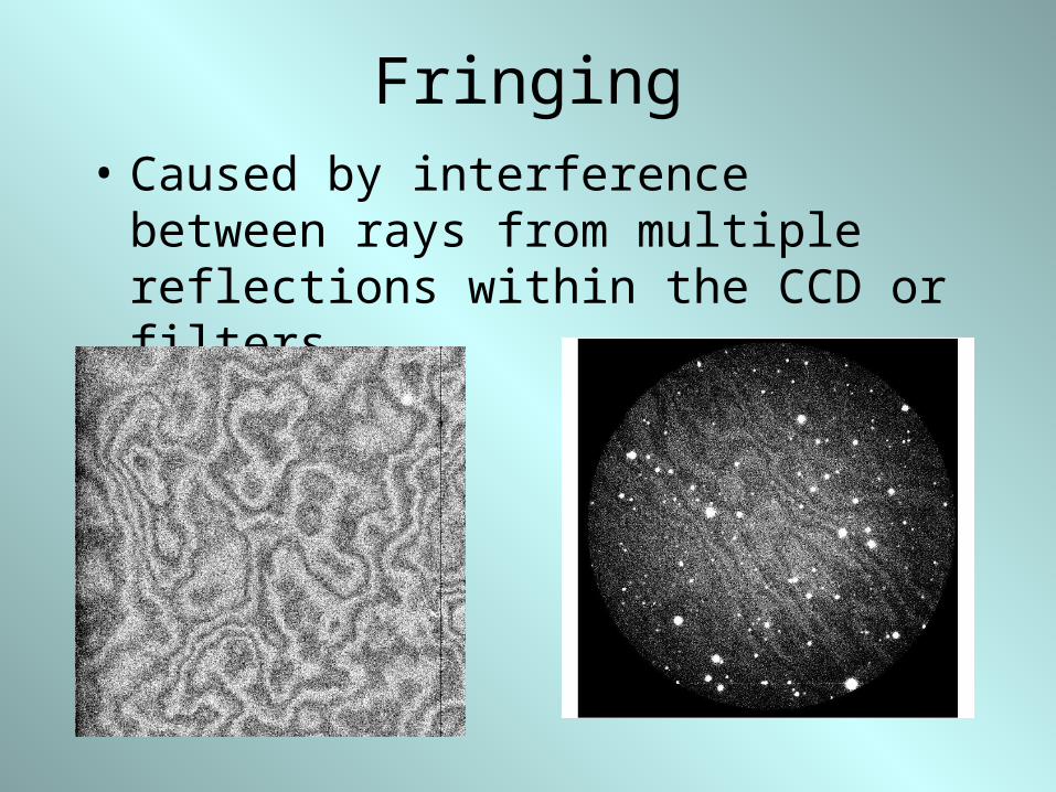
Fringing• Caused by interference between rays from
multiple reflections within the CCD or filters.

Bad pixels
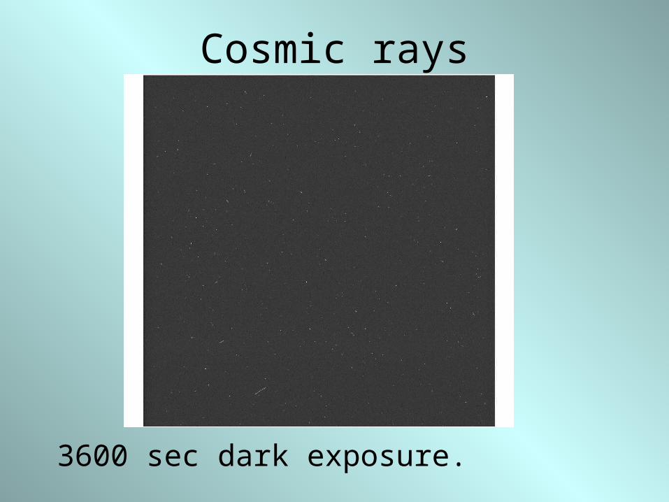
Cosmic rays
3600 sec dark exposure.

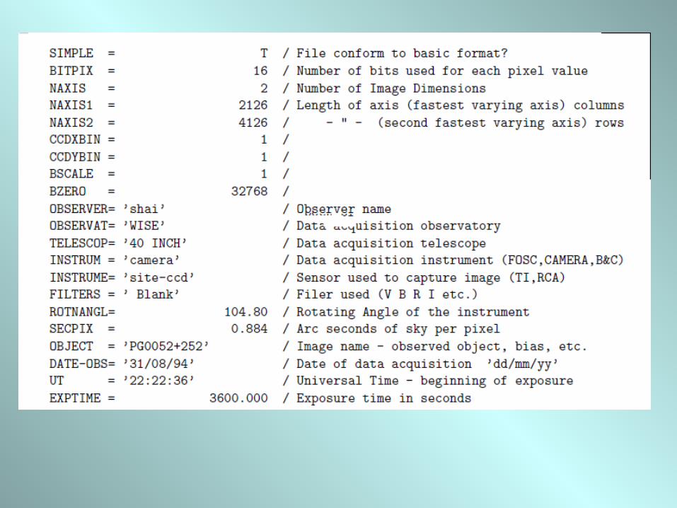
Flexible Image Transport System (FITS)• Digital file format used to store, transmit, and manipulate scientific
and other images. Most commonly used in astronomy. Designed specifically for scientific data and hence includes many provisions for describing photometric and spatial calibration information, together with image original metadata.
• First part of the file has an ASCII header that carry keyword/value pairs which provide information such as size, origin, coordinates, binary data format, free-form comments, history of the data, etc.
• Second part of the file has the actual data in a binary format.
• FITS is also often used to store non-image data, such as spectra, photon lists, data cubes, or even structured data such as multi-table databases. A FITS file may contain several extensions, and each of these may contain a data object. For example, it is possible to store x-ray and infrared exposures in the same file.