Embed Size (px)
Citation preview
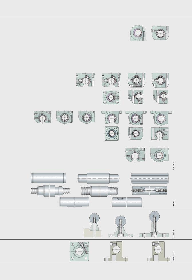
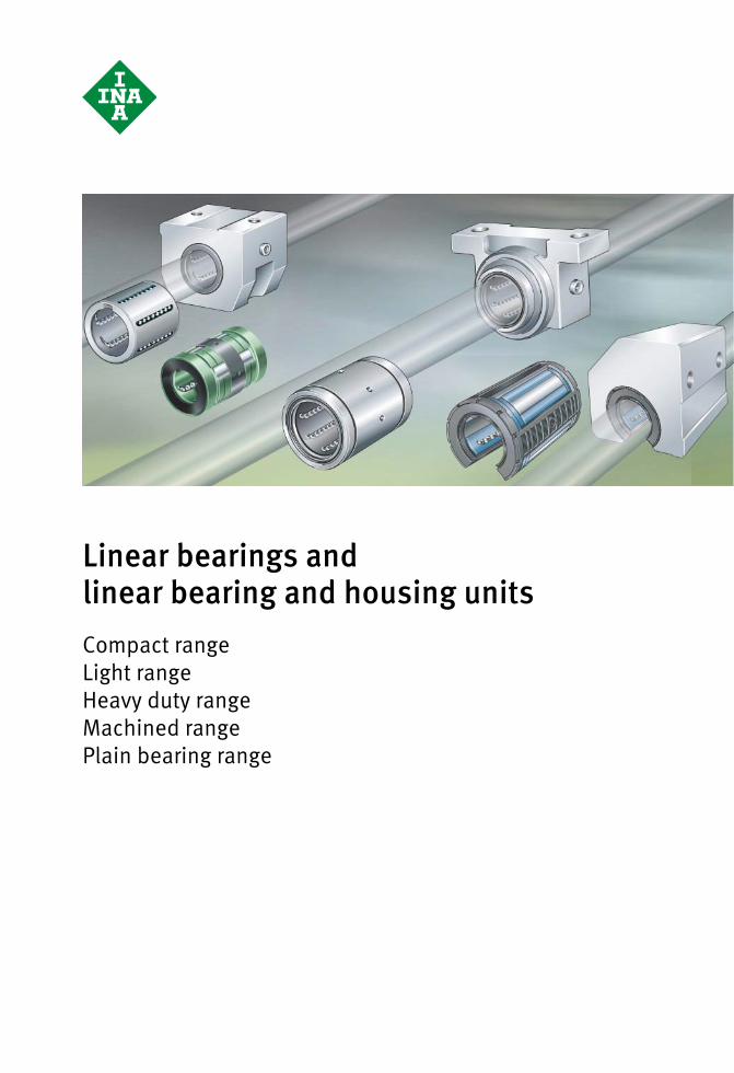
Shaft Guidance SystemsLinear bearings, linear bearing and housing units
Solid shafts, hollow shafts Shaft and support rail units
Shaft support blocks

Shaft Guidance SystemsLinear bearings, linear bearing and housing units
Solid shafts, hollow shaftsShaft and support rail units
Shaft support blocks

All data have been prepared with a great deal
of care and checked for their accuracy but
no liability can be accepted for any errors or
omissions. We reserve the right to make
technical modifications.
© Schaeffler Technologies GmbH & Co. KG
Issued: 2014, February
Reproduction in whole or in part without
our authorisation is prohibited.
Foreword
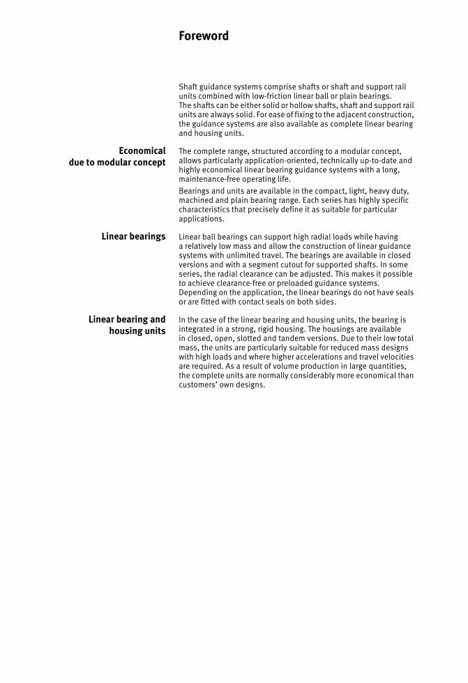
Shaft guidance systems comprise shafts or shaft and support rail units combined with low-friction linear ball or plain bearings.The shafts can be either solid or hollow shafts, shaft and support rail units are always solid. For ease of fixing to the adjacent construction, the guidance systems are also available as complete linear bearing and housing units.
Economicaldue to modular concept
The complete range, structured according to a modular concept, allows particularly application-oriented, technically up-to-date and highly economical linear bearing guidance systems with a long, maintenance-free operating life.Bearings and units are available in the compact, light, heavy duty, machined and plain bearing range. Each series has highly specific characteristics that precisely define it as suitable for particular applications.
Linear bearings Linear ball bearings can support high radial loads while havinga relatively low mass and allow the construction of linear guidance systems with unlimited travel. The bearings are available in closed versions and with a segment cutout for supported shafts. In some series, the radial clearance can be adjusted. This makes it possible to achieve clearance-free or preloaded guidance systems. Depending on the application, the linear bearings do not have seals or are fitted with contact seals on both sides.
Linear bearing andhousing units
In the case of the linear bearing and housing units, the bearing is integrated in a strong, rigid housing. The housings are availablein closed, open, slotted and tandem versions. Due to their low total mass, the units are particularly suitable for reduced mass designs with high loads and where higher accelerations and travel velocities are required. As a result of volume production in large quantities,the complete units are normally considerably more economical than customers’ own designs.

4 WF 1 Schaeffler Technologies
Schaeffler Technologies WF 1 5
Page
Contents
Product index ......................................................................... 6
Product overview .................................................................... 10
Shaft guidance systemsTechnical principles ........................................................... 12
Linear bearings, linear bearing and housing units............... 44
Solid shafts, hollow shafts ................................................. 104
Shaft and support rail units................................................ 128
Shaft support blocks.......................................................... 144
Addresses .............................................................................. 156
6 WF 1 Schaeffler Technologies
Page
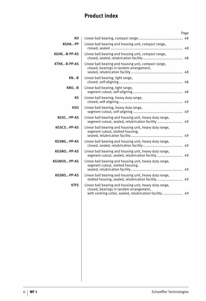
Product index
KH Linear ball bearing, compact range............................................ 48
KGHA..-PP Linear ball bearing and housing unit, compact range,closed, sealed ....................................................................... 48
KGHK..-B-PP-AS Linear ball bearing and housing unit, compact range,closed, sealed, relubrication facility ....................................... 48
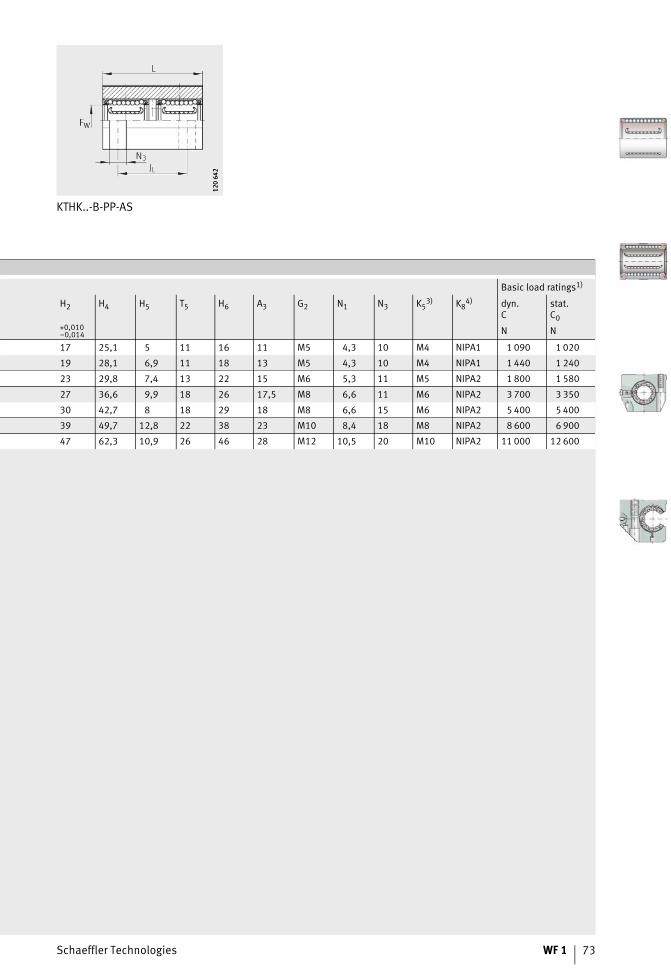
KTHK..-B-PP-AS Linear ball bearing and housing unit, compact range,closed, bearings in tandem arrangement,sealed, relubrication facility ................................................... 48
KN..-B Linear ball bearing, light range,closed, self-aligning............................................................... 48
KNO..-B Linear ball bearing, light range,segment cutout, self-aligning ................................................. 48
KS Linear ball bearing, heavy duty range,closed, self-aligning............................................................... 49
KSO Linear ball bearing, heavy duty range,segment cutout, self-aligning ................................................. 49
KGSC..-PP-AS Linear ball bearing and housing unit, heavy duty range,segment cutout, sealed, relubrication facility ......................... 49
KGSCS..-PP-AS Linear ball bearing and housing unit, heavy duty range,segment cutout, slotted housing,sealed, relubrication facility ................................................... 49
KGSNG..-PP-AS Linear ball bearing and housing unit, heavy duty range,closed, sealed, relubrication facility ....................................... 49
KGSNO..-PP-AS Linear ball bearing and housing unit, heavy duty range,segment cutout, sealed, relubrication facility ......................... 49
KGSNOS..-PP-AS Linear ball bearing and housing unit, heavy duty range,segment cutout, slotted housing,sealed, relubrication facility ................................................... 49
KGSNS..-PP-AS Linear ball bearing and housing unit, heavy duty range,slotted housing, sealed, relubrication facility ......................... 49
KTFS Linear ball bearing and housing unit, heavy duty range,closed, bearings in tandem arrangement,with centring collar, sealed, relubrication facility .................... 49
Schaeffler Technologies WF 1 7
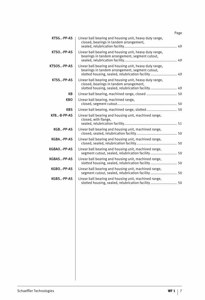
PageKTSG..-PP-AS Linear ball bearing and housing unit, heavy duty range,
closed, bearings in tandem arrangement,sealed, relubrication facility.................................................... 49
KTSO..-PP-AS Linear ball bearing and housing unit, heavy duty range,bearings in tandem arrangement, segment cutout,sealed, relubrication facility.................................................... 49
KTSOS..-PP-AS Linear ball bearing and housing unit, heavy duty range,bearings in tandem arrangement, segment cutout,slotted housing, sealed, relubrication facility .......................... 49
KTSS..-PP-AS Linear ball bearing and housing unit, heavy duty range,closed, bearings in tandem arrangement,slotted housing, sealed, relubrication facility .......................... 49
KB Linear ball bearing, machined range, closed .............................. 50
KBO Linear ball bearing, machined range,closed, segment cutout........................................................... 50
KBS Linear ball bearing, machined range, slotted.............................. 50
KFB..-B-PP-AS Linear ball bearing and housing unit, machined range,closed, with flange,sealed, relubrication facility.................................................... 51
KGB..-PP-AS Linear ball bearing and housing unit, machined range,closed, sealed, relubrication facility........................................ 50
KGBA..-PP-AS Linear ball bearing and housing unit, machined range,closed, sealed, relubrication facility........................................ 50
KGBAO..-PP-AS Linear ball bearing and housing unit, machined range,segment cutout, sealed, relubrication facility .......................... 50
KGBAS..-PP-AS Linear ball bearing and housing unit, machined range,slotted housing, sealed, relubrication facility .......................... 50
KGBO..-PP-AS Linear ball bearing and housing unit, machined range,segment cutout, sealed, relubrication facility .......................... 50
KGBS..-PP-AS Linear ball bearing and housing unit, machined range,slotted housing, sealed, relubrication facility .......................... 50
Product index
8 WF 1 Schaeffler Technologies
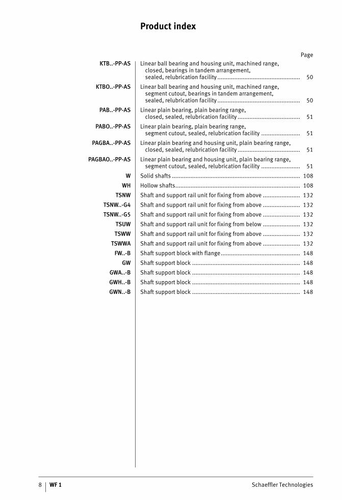
PageKTB..-PP-AS Linear ball bearing and housing unit, machined range,
closed, bearings in tandem arrangement,sealed, relubrication facility ................................................. 50
KTBO..-PP-AS Linear ball bearing and housing unit, machined range,segment cutout, bearings in tandem arrangement,sealed, relubrication facility ................................................. 50
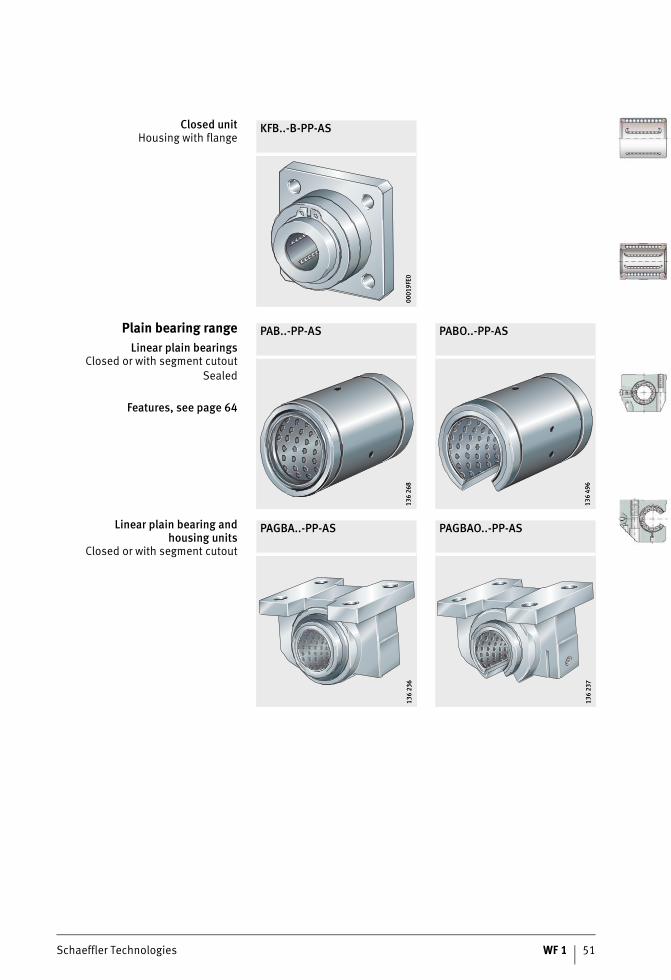
PAB..-PP-AS Linear plain bearing, plain bearing range,closed, sealed, relubrication facility ..................................... 51
PABO..-PP-AS Linear plain bearing, plain bearing range,segment cutout, sealed, relubrication facility ....................... 51
PAGBA..-PP-AS Linear plain bearing and housing unit, plain bearing range,closed, sealed, relubrication facility ..................................... 51
PAGBAO..-PP-AS Linear plain bearing and housing unit, plain bearing range,segment cutout, sealed, relubrication facility ....................... 51
W Solid shafts ............................................................................ 108
WH Hollow shafts.......................................................................... 108
TSNW Shaft and support rail unit for fixing from above ...................... 132
TSNW..-G4 Shaft and support rail unit for fixing from above ...................... 132
TSNW..-G5 Shaft and support rail unit for fixing from above ...................... 132
TSUW Shaft and support rail unit for fixing from below ...................... 132
TSWW Shaft and support rail unit for fixing from above ...................... 132
TSWWA Shaft and support rail unit for fixing from above ...................... 132
FW..-B Shaft support block with flange............................................... 148
GW Shaft support block ................................................................ 148
GWA..-B Shaft support block ................................................................ 148
GWH..-B Shaft support block ................................................................ 148
GWN..-B Shaft support block ................................................................ 148

Schaeffler Technologies WF 1 9
0001
9C1E
120
586
120
586
0001
9C1F
0007
FCF2
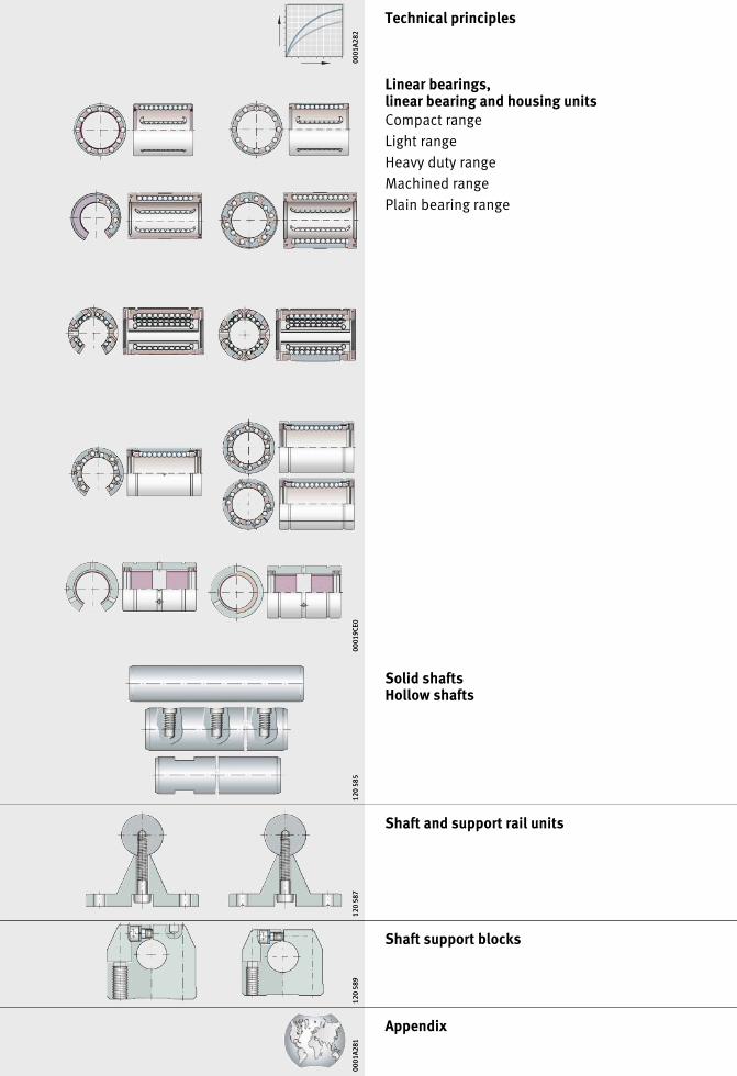
Technical principles
Linear bearings,linear bearing and housing unitsCompact rangeLight rangeHeavy duty rangeMachined rangePlain bearing range
Solid shaftsHollow shafts
Shaft and support rail units
Shaft support blocks
Appendix
0001
A282
0001
A282
0001
9CE0
0001
9CE0
120
585
120
585
120
587
120
587
120
589
120
589
0001
A281
0001
A281
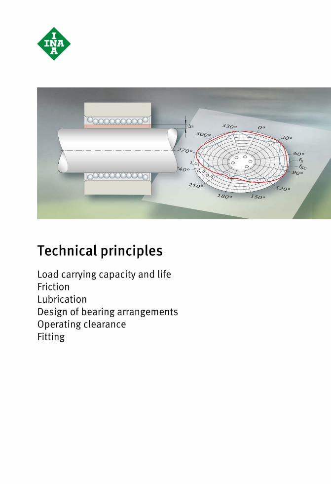
Technical principlesLoad carrying capacity and lifeFrictionLubricationDesign of bearing arrangementsOperating clearanceFitting
Schaeffler Technologies WF 1 13
Page
Technical principles
Load carrying capacity and life Basic rating life ......................................................................... 15
Operating life ............................................................................ 16
Static load safety factor ............................................................. 16
Influence of the shaft raceway on basic load ratings................... 17Differences in raceway hardness ........................................... 17
Load direction and position of the ball rows ............................... 18Main load direction ............................................................... 18Linear ball bearings .............................................................. 19Linear ball bearing and housing units.................................... 19
Misalignment of the shaft .......................................................... 25Load factors in misalignment ................................................ 25Compensation of misalignmentsin the light and heavy duty range........................................... 26
Friction Coefficient of friction ................................................................. 27Coefficient of friction in unsealed bearings ............................ 27
Lubrication Grease lubrication ..................................................................... 28Structure of suitable greases................................................. 28Initial greasing and operating life .......................................... 28Relubrication of linear ball bearings in housings.................... 29
Lubrication nipples for housings................................................ 30
Application in special environments .......................................... 32
Oil lubrication ........................................................................... 32Suitable oils ......................................................................... 32
Designof bearing arrangements
Location .................................................................................... 33Linear ball bearings KH ......................................................... 33Linear ball bearings KN..-B, KB, KS andplain bearings PAB................................................................ 33Linear ball bearings KNO..-B, KBO andplain bearings PABO ............................................................. 34Linear ball bearing and housing units.................................... 35
Sealing...................................................................................... 36Gap seals or contact seals..................................................... 36
14 WF 1 Schaeffler Technologies
Page
Technical principles
Operating clearance Tolerance and operating clearance............................................ 37
Mounting tolerances and operating clearance ........................... 38
Mounting Mounting of bearings................................................................ 39Linear ball bearings KH......................................................... 39Linear ball bearings KN..-B, KNO..-B, KB, KBS, KBO, KS, KSOand linear plain bearings PAB, PABO..................................... 40
Alignment of bearings and shafts .............................................. 41Bearings arranged in series .................................................. 41Bearings arranged in parallel ................................................ 41Very long guidance systems with supported shaft ................. 42Guidance systems with clearance-free orpreloaded bearings .............................................................. 42Parallel shaft and support rail units ...................................... 42
Setting the operating clearance................................................. 43Setting bearings clearance-free ............................................ 43Setting the preload............................................................... 43
Suspended arrangement of guidance system ............................ 43
Schaeffler Technologies WF 1 15
Load carrying capacity and life
The size of a linear ball bearing is determined by the demandsmade in terms of load carrying capacity, rating life and operational security.The load carrying capacity is described in terms of:■ the basic dynamic load rating C■ the basic static load rating C0.The calculation of the basic dynamic and static load ratings given in the dimension tables is based on DIN 636-1.
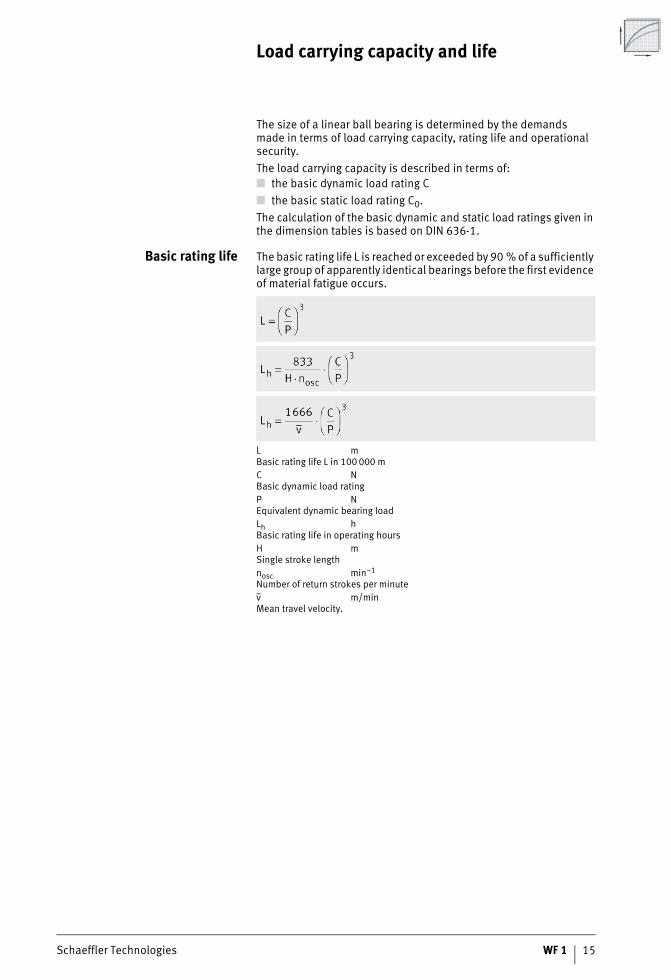
Basic rating life The basic rating life L is reached or exceeded by 90 % of a sufficiently large group of apparently identical bearings before the first evidence of material fatigue occurs.
L mBasic rating life L in 100 000 mC NBasic dynamic load ratingP NEquivalent dynamic bearing loadLh hBasic rating life in operating hoursH mSingle stroke lengthnosc min–1
Number of return strokes per minutev m/minMean travel velocity.
16 WF 1 Schaeffler Technologies
Load carrying capacity and life
Operating life The operating life is defined as the life actually achieved by a shaft guidance system. It may differ significantly from the calculated life.The following influences can lead to premature failure through wear or fatigue:■ misalignment between the guideways and guidance elements■ contamination■ inadequate lubrication■ reciprocating motion with very small stroke length
(false brinelling)■ vibration during stoppage (false brinelling).Due to the wide variety of mounting and operating conditions, it is not possible to precisely predetermine the operating life of a shaft guidance system. The safest way to arrive at an appropriate estimate of the operating life is comparison with similar applications.
Static load safety factor The static load safety factor S0 indicates the security against imper-missible permanent deformations in the bearing and is determined by means of the following equation.
S0 –Static load safety factorC0 NBasic static load ratingP0 NEquivalent static load.
For linear ball bearings KH and KN..-B, the value must be S0 � 4.In relation to guidance accuracy and smooth running, a valueof S0 � 2 is regarded as permissible. If S0 � 2, please contact us.
Schaeffler Technologies WF 1 17
Influence of the shaft racewayon the basic load ratings
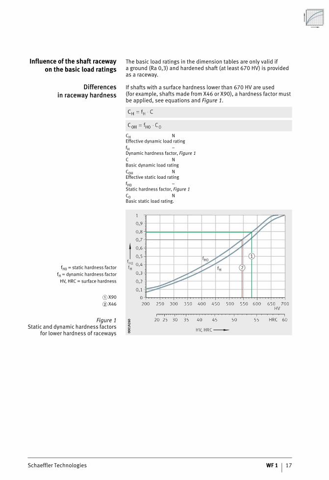
The basic load ratings in the dimension tables are only valid ifa ground (Ra 0,3) and hardened shaft (at least 670 HV) is provided as a raceway.
Differencesin raceway hardness
If shafts with a surface hardness lower than 670 HV are used(for example, shafts made from X46 or X90), a hardness factor must be applied, see equations and Figure 1.
CH NEffective dynamic load ratingfH –Dynamic hardness factor, Figure 1C NBasic dynamic load ratingC0H NEffective static load ratingfH0 –Static hardness factor, Figure 1C0 NBasic static load rating.
fH0 = static hardness factorfH = dynamic hardness factor
HV, HRC = surface hardness
� X90� X46
Figure 1Static and dynamic hardness factors
for lower hardness of raceways 0001
A260
0001
A260
18 WF 1 Schaeffler Technologies
Load carrying capacity and life
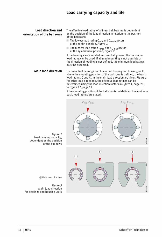
Load direction andorientation of the ball rows
The effective load rating of a linear ball bearing is dependenton the position of the load direction in relation to the positionof the ball rows:■ The lowest load rating Cmin and C0 min occurs
at the zenith position, Figure 2.■ The highest load rating Cmax and C0 max occurs
at the symmetrical position, Figure 2.If the bearings are mounted in correct alignment, the maximumload rating can be used. If aligned mounting is not possible orthe direction of loading is not defined, the minimum load ratings must be assumed.
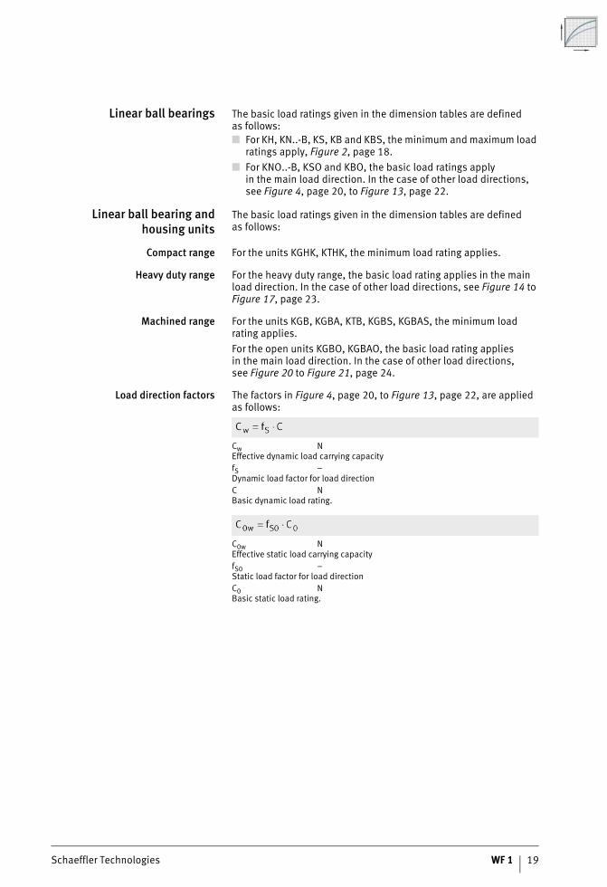
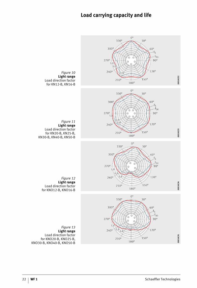
Main load direction For linear ball bearings and linear ball bearing and housing units where the mounting position of the ball rows is defined, the basic load ratings C and C0 in the main load direction are given, Figure 3. For other load directions, the effective load ratings can be determined using the load direction factors in Figure 4, page 20,to Figure 21, page 24.If the mounting position of the ball rows is not defined, the minimum basic load ratings are stated.
Figure 2Load carrying capacity,
dependent on the positionof the ball rows 12
0 30
812
0 30
8
� Main load direction
Figure 3Main load direction
for bearings and housing units 120
309
120
309
Schaeffler Technologies WF 1 19
Linear ball bearings The basic load ratings given in the dimension tables are definedas follows:■ For KH, KN..-B, KS, KB and KBS, the minimum and maximum load
ratings apply, Figure 2, page 18.■ For KNO..-B, KSO and KBO, the basic load ratings apply
in the main load direction. In the case of other load directions, see Figure 4, page 20, to Figure 13, page 22.
Linear ball bearing andhousing units
The basic load ratings given in the dimension tables are definedas follows:
Compact range For the units KGHK, KTHK, the minimum load rating applies.
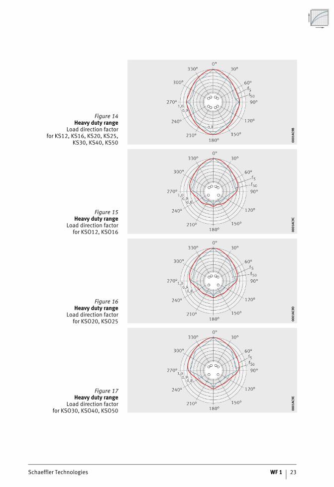
Heavy duty range For the heavy duty range, the basic load rating applies in the main load direction. In the case of other load directions, see Figure 14 to Figure 17, page 23.
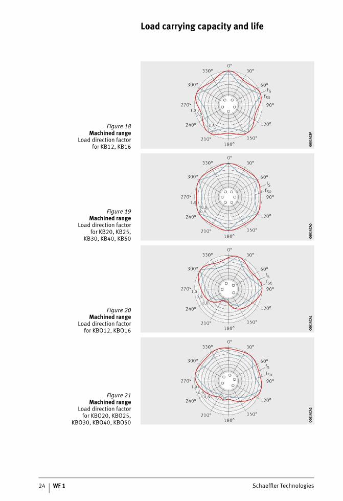
Machined range For the units KGB, KGBA, KTB, KGBS, KGBAS, the minimum load rating applies.For the open units KGBO, KGBAO, the basic load rating appliesin the main load direction. In the case of other load directions,see Figure 20 to Figure 21, page 24.
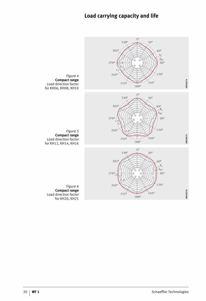
Load direction factors The factors in Figure 4, page 20, to Figure 13, page 22, are applied as follows:
Cw NEffective dynamic load carrying capacityfS –Dynamic load factor for load directionC NBasic dynamic load rating.
C0w NEffective static load carrying capacityfS0 –Static load factor for load directionC0 NBasic static load rating.
20 WF 1 Schaeffler Technologies
Load carrying capacity and life
Figure 4Compact range
Load direction factorfor KH06, KH08, KH10 00
01AC
7400
01AC
74
Figure 5Compact range
Load direction factorfor KH12, KH14, KH16 00
01AC
7500
01AC
75Figure 6
Compact rangeLoad direction factor
for KH20, KH25 0001
AC76
0001
AC76
Schaeffler Technologies WF 1 21
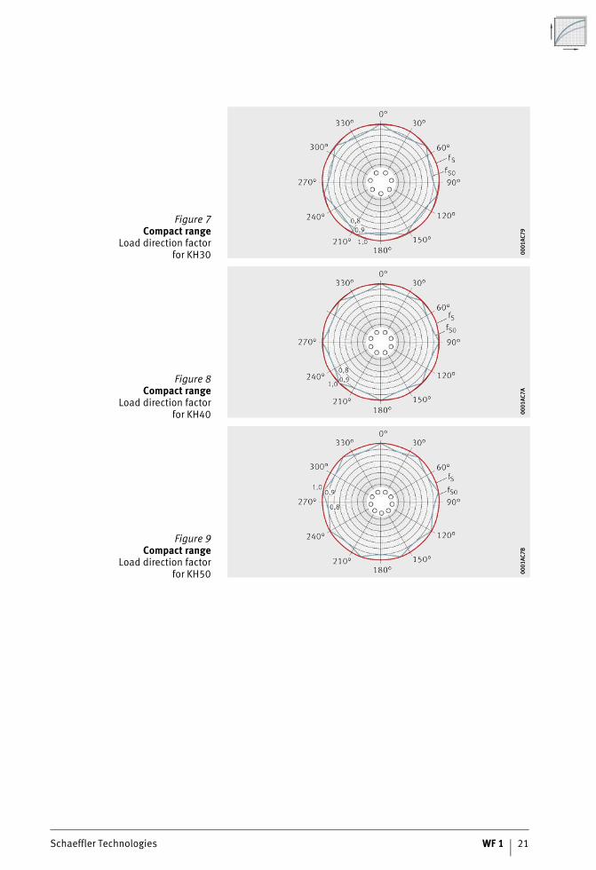
Figure 7Compact range
Load direction factorfor KH30 00
01AC
7900
01AC
79
Figure 8Compact range
Load direction factorfor KH40 00
01AC
7A00
01AC
7A
Figure 9Compact range
Load direction factorfor KH50 00
01AC
7B00
01AC
7B
22 WF 1 Schaeffler Technologies
Load carrying capacity and life
Figure 10Light range
Load direction factorfor KN12-B, KN16-B 00
01AC
9200
01AC
92
Figure 11Light range
Load direction factorfor KN20-B, KN25-B,
KN30-B, KN40-B, KN50-B 0001
AC93
0001
AC93
Figure 12Light range
Load direction factorfor KNO12-B, KNO16-B 00
01AC
9400
01AC
94
Figure 13Light range
Load direction factorfor KNO20-B, KNO25-B,
KNO30-B, KNO40-B, KNO50-B 0001
AC95
0001
AC95
Schaeffler Technologies WF 1 23
Figure 14Heavy duty range
Load direction factorfor KS12, KS16, KS20, KS25,
KS30, KS40, KS50 0001
AC9B
0001
AC9B
Figure 15Heavy duty range
Load direction factorfor KSO12, KSO16 00
01AC
9C00
01AC
9C
Figure 16Heavy duty range
Load direction factorfor KSO20, KSO25 00
01AC
9D00
01AC
9D
Figure 17Heavy duty range
Load direction factorfor KSO30, KSO40, KSO50 00
01AC
9E00
01AC
9E
24 WF 1 Schaeffler Technologies
Load carrying capacity and life
Figure 18Machined range
Load direction factorfor KB12, KB16 00
01AC
9F00
01AC
9F
Figure 19Machined range
Load direction factorfor KB20, KB25,
KB30, KB40, KB50 0001
ACA0
0001
ACA0
Figure 20Machined range
Load direction factorfor KBO12, KBO16 00
01AC
A100
01AC
A1
Figure 21Machined range
Load direction factorfor KBO20, KBO25,
KBO30, KBO40, KBO50 0001
ACA2
0001
ACA2
Schaeffler Technologies WF 1 25
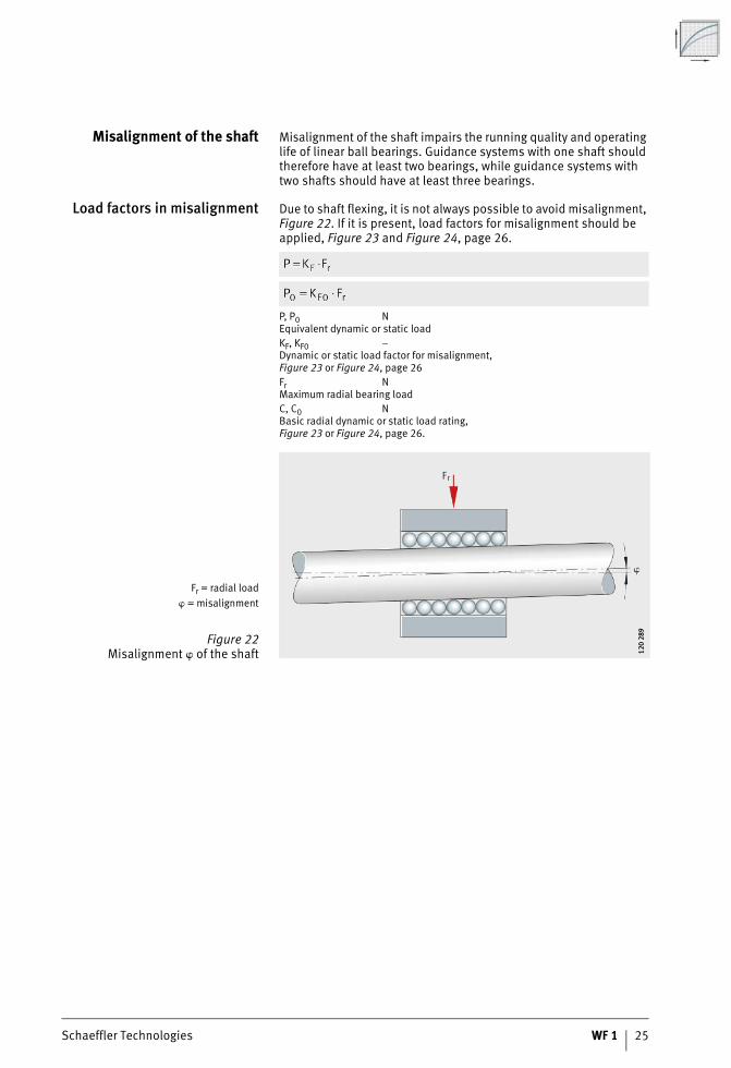
Misalignment of the shaft Misalignment of the shaft impairs the running quality and operating life of linear ball bearings. Guidance systems with one shaft should therefore have at least two bearings, while guidance systems with two shafts should have at least three bearings.
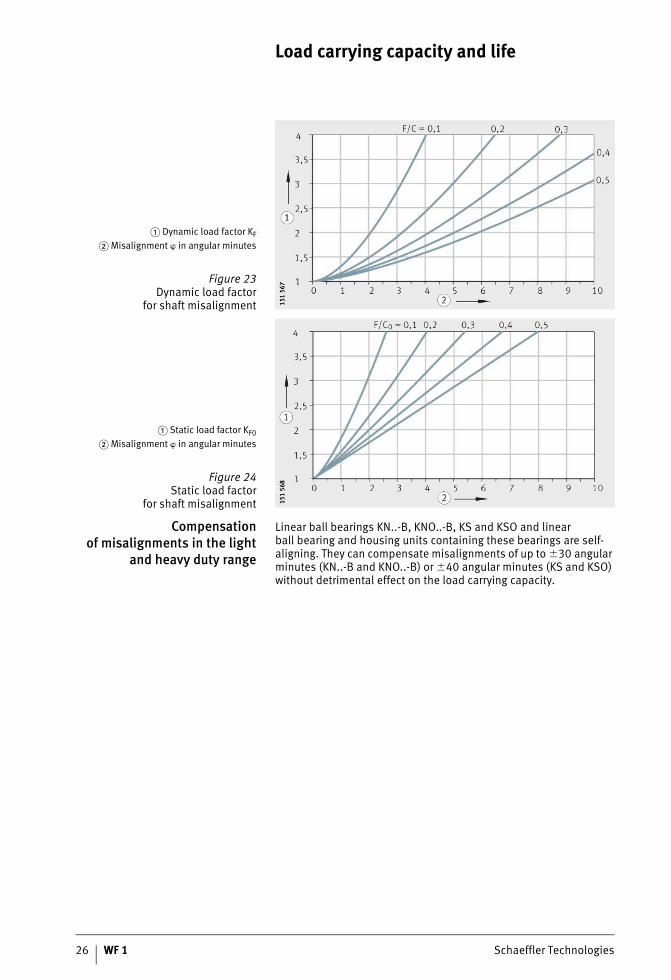
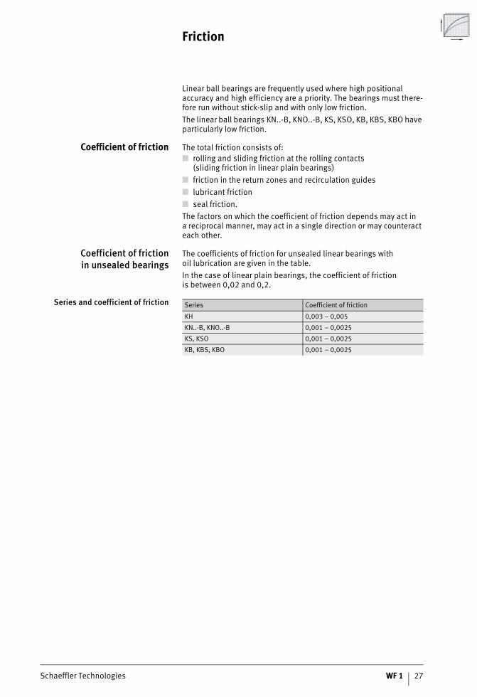
Load factors in misalignment Due to shaft flexing, it is not always possible to avoid misalignment, Figure 22. If it is present, load factors for misalignment should be applied, Figure 23 and Figure 24, page 26.
P, P0 NEquivalent dynamic or static loadKF, KF0 –Dynamic or static load factor for misalignment,Figure 23 or Figure 24, page 26Fr NMaximum radial bearing loadC, C0 NBasic radial dynamic or static load rating,Figure 23 or Figure 24, page 26.
Fr = radial load� = misalignment
Figure 22Misalignment � of the shaft 12
0 28
912
0 28
9
26 WF 1 Schaeffler Technologies
Load carrying capacity and life
Compensationof misalignments in the light
and heavy duty range
Linear ball bearings KN..-B, KNO..-B, KS and KSO and linearball bearing and housing units containing these bearings are self-aligning. They can compensate misalignments of up to �30 angular minutes (KN..-B and KNO..-B) or �40 angular minutes (KS and KSO) without detrimental effect on the load carrying capacity.
� Dynamic load factor KF� Misalignment � in angular minutes
Figure 23Dynamic load factor
for shaft misalignment 151
567
151
567
� Static load factor KF0� Misalignment � in angular minutes
Figure 24Static load factor
for shaft misalignment 151
568
151
568
Schaeffler Technologies WF 1 27
Friction
Linear ball bearings are frequently used where high positional accuracy and high efficiency are a priority. The bearings must there-fore run without stick-slip and with only low friction.The linear ball bearings KN..-B, KNO..-B, KS, KSO, KB, KBS, KBO have particularly low friction.
Coefficient of friction The total friction consists of:■ rolling and sliding friction at the rolling contacts
(sliding friction in linear plain bearings)■ friction in the return zones and recirculation guides■ lubricant friction■ seal friction.The factors on which the coefficient of friction depends may act ina reciprocal manner, may act in a single direction or may counteract each other.
Coefficient of frictionin unsealed bearings
The coefficients of friction for unsealed linear bearings withoil lubrication are given in the table.In the case of linear plain bearings, the coefficient of frictionis between 0,02 and 0,2.
Series and coefficient of friction Series Coefficient of friction
KH 0,003 – 0,005
KN..-B, KNO..-B 0,001 – 0,0025
KS, KSO 0,001 – 0,0025
KB, KBS, KBO 0,001 – 0,0025
28 WF 1 Schaeffler Technologies
Lubrication
Open linear ball bearings are supplied with a wet or dry preservative and can be lubricated using either grease or oil. The oil-based preservative is compatible and miscible with lubricants witha mineral oil base, which means that it is not generally necessaryto wash out the bearings before mounting.Bearings with a dry preservative must be greased oroiled immediately after they are removed from the packaging.
Grease lubrication Grease lubrication should be used in preference to oil lubrication, since the grease adheres to the inside of the bearing and thus prevents the ingress of contamination. This sealing effect protects the rolling elements against corrosion.In addition, the design work involved in providing grease lubrication is less than that for providing oil, since design of the sealing arrangement is less demanding.
Compositionof suitable greases
The greases for linear ball bearings have the following composition:■ lithium or lithium complex soap■ base oil: mineral oil or poly-alpha-olefin (PAO)■ special anti-wear additives for loads C/P � 8,
indicated by “P” in the DIN designation KP2K–30■ consistency to NLGI grade 2 in accordance with DIN 51818.
Initial greasing andoperating life
Based on experience, the operating life is achieved when bearings are operated with grease lubrication in normal environmental conditions (C/P � 10), at room temperature and at v � 0,6 · vmax.If it is not possible to achieve these conditions, the bearings must be relubricated.Sealed linear ball bearings are already adequately greased when delivered and are therefore maintenance-free in many applications.
Initial greasing andrelubrication of bearings
The initial greasing and relubrication of linear ball bearings without seals and relubrication holes must be carried out via the shaft.It must be ensured that all rolling elements come into contact with grease during recirculation. The bearing must be moved over at least twice its length during relubrication.During initial greasing, the bearing fitted on the shaft should be fed with lubricant until this begins to emerge from the bearing.In the case of the linear ball bearings KH, KN..-B-PP-AS,KS..-PP-AS and PAB..-PP-AS, relubrication can be carried out via holes or openings in the retaining ring or outer ring.
Schaeffler Technologies WF 1 29
Relubrication interval The relubrication interval is dependent on many operating conditions such as load, temperature, speed, stroke length, lubricant, environmental conditions and the mounting position.Precise lubrication intervals should be determined by tests conducted under application conditions.
Relubricationof linear ball bearings
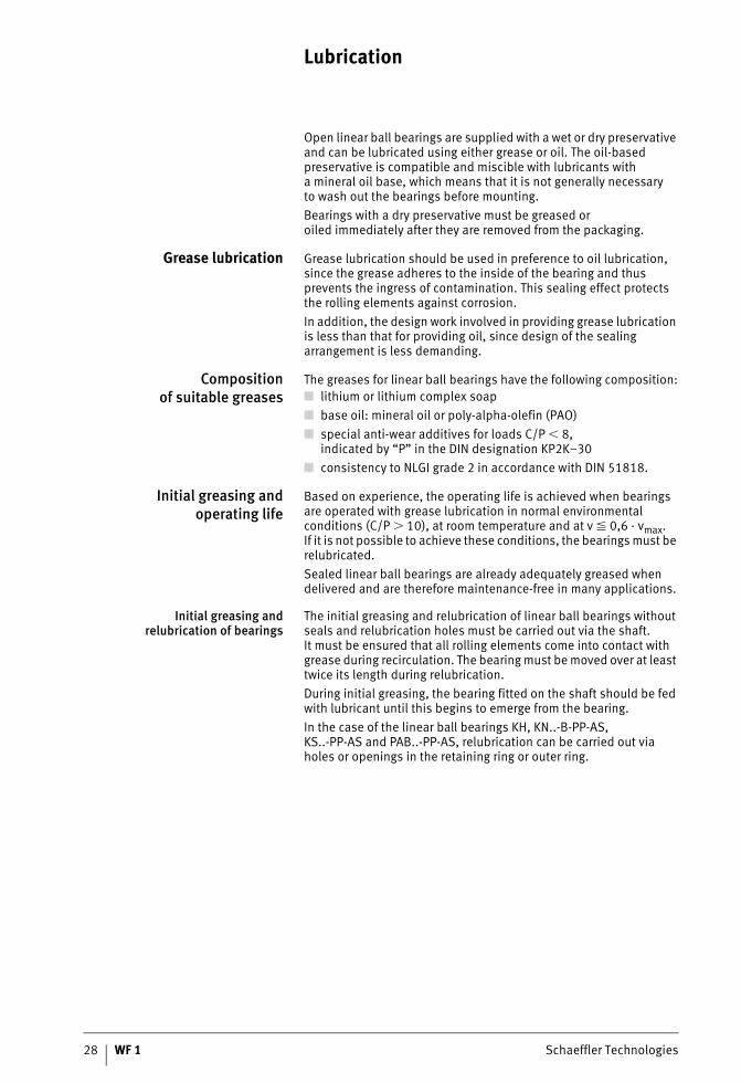
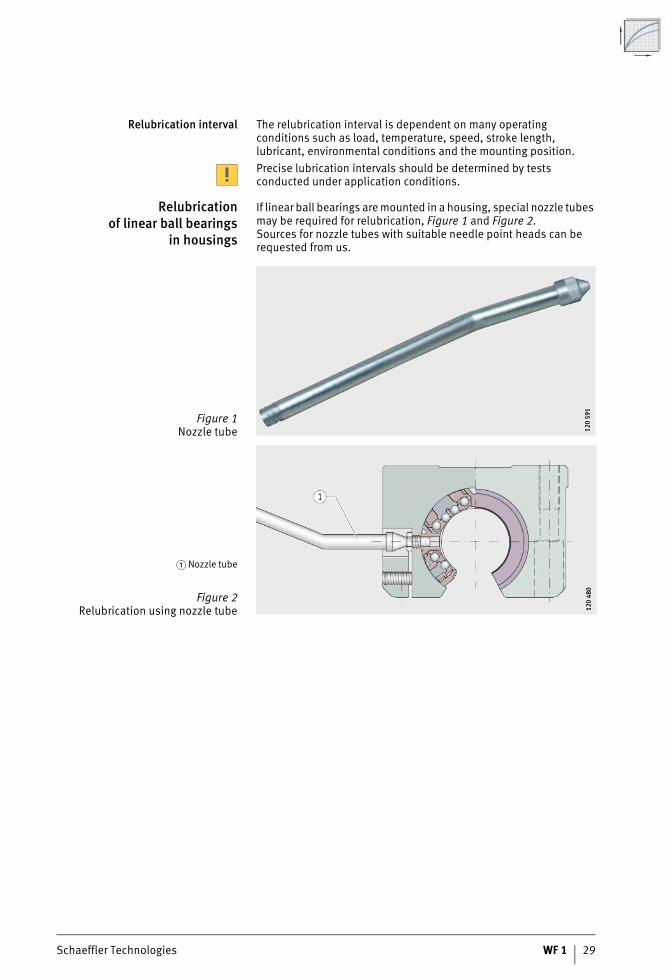
in housings
If linear ball bearings are mounted in a housing, special nozzle tubes may be required for relubrication, Figure 1 and Figure 2.Sources for nozzle tubes with suitable needle point heads can be requested from us.
Figure 1Nozzle tube 12
0 59
112
0 59
1
� Nozzle tube
Figure 2Relubrication using nozzle tube 12
0 48
012
0 48
0
30 WF 1 Schaeffler Technologies
Lubrication
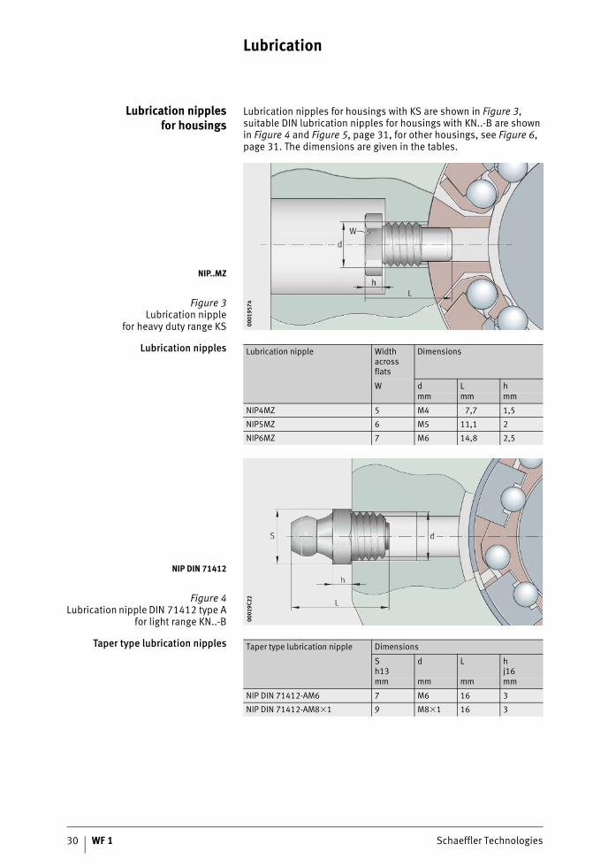
Lubrication nipplesfor housings
Lubrication nipples for housings with KS are shown in Figure 3, suitable DIN lubrication nipples for housings with KN..-B are shown in Figure 4 and Figure 5, page 31, for other housings, see Figure 6, page 31. The dimensions are given in the tables.
Lubrication nipples
Taper type lubrication nipples
NIP..MZ
Figure 3Lubrication nipple
for heavy duty range KS 0001
9574
0001
9574
Lubrication nipple Width across flats
Dimensions
W d L hmm mm mm
NIP4MZ 5 M4 7,7 1,5
NIP5MZ 6 M5 11,1 2
NIP6MZ 7 M6 14,8 2,5
NIP DIN 71412
Figure 4Lubrication nipple DIN 71412 type A
for light range KN..-B 0001
9C22
0001
9C22
Taper type lubrication nipple Dimensions
Sh13
d L hj16
mm mm mm mm
NIP DIN 71412-AM6 7 M6 16 3
NIP DIN 71412-AM8�1 9 M8�1 16 3
Schaeffler Technologies WF 1 31
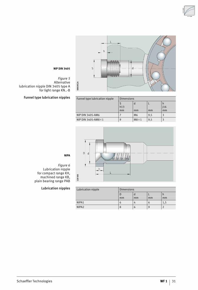
Funnel type lubrication nipples
Lubrication nipples
NIP DIN 3405
Figure 5Alternative
lubrication nipple DIN 3405 type Afor light range KN..-B 00
019C
2400
019C
24
Funnel type lubrication nipple Dimensions
Sh13
d L hj16
mm mm mm mm
NIP DIN 3405-AM6 7 M6 9,5 3
NIP DIN 3405-AM8�1 9 M8�1 9,5 3
NIPA
Figure 6Lubrication nipple
for compact range KH,machined range KB,
plain bearing range PAB 120
505
120
505
Lubrication nipple Dimensions
D d L hmm mm mm mm
NIPA1 6 4 6 1,5
NIPA2 8 6 9 2
32 WF 1 Schaeffler Technologies
Lubrication
Applicationin special environments
In vacuum applications, lubricants with low vapourisation rates are required in order to maintain the vacuum atmosphere.In the foodstuffs sector and clean rooms, special requirements are also placed on lubricants in relation to emissions and compatibility. For such environmental conditions, please consult us.
Oil lubrication Oil lubrication should be used in preference if heat is to be dissipated and contaminants are to be carried out of the bearing by the lubricant.This advantage should be set against the increased design work required (lubricant feed, sealing).
Suitable oils As a function of the load case, we recommend the following oils:■ for low to moderate loads (C/P � 15):
– hydraulic oils HL to DIN 51524 and oils CL to DIN 51517in the viscosity range ISO-VG 10 to ISO-VG 22
■ for high loads (C/P � 8):– hydraulic oils HLP to DIN 51524 and oils CLP to DIN 51517
in the viscosity range ISO-VG 68 to ISO-VG 100.
Schaeffler Technologies WF 1 33
Design of bearing arrangements
The good running characteristics of shaft guidance systems are dependent not only on the bearings. The geometrical and positional tolerances of the adjacent construction also play a significant role.The higher the accuracy to which the adjacent construction is produced and assembled, the better the running characteristics.
LocationLinear ball bearings KH Linear ball bearings KH and KH..-PP are pressed into the housing
bore. This provides axial and radial location. No additional meansof location are required.
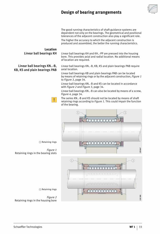
Linear ball bearings KN..-B,KB, KS and plain bearings PAB
Linear ball bearings KN..-B, KB, KS and plain bearings PAB require axial location.Linear ball bearings KB and plain bearings PAB can be locatedby means of retaining rings or by the adjacent construction, Figure 1 to Figure 3, page 34.Linear ball bearings KN..-B and KS can be located in accordancewith Figure 2 and Figure 3, page 34.Linear ball bearings KN..-B can also be located by means of a screw, Figure 4, page 34.The series KN..-B and KS should not be located by means of shaft retaining rings according to Figure 1. This could impair the function of the bearing.
� Retaining rings
Figure 1Retaining rings in the bearing slots 12
0 64
712
0 64
7
� Retaining rings
Figure 2Retaining rings in the housing bore 12
0 30
012
0 30
0
34 WF 1 Schaeffler Technologies
Design of bearing arrangements
Linear ball bearings KNO..-B,KBO and plain bearings PABO
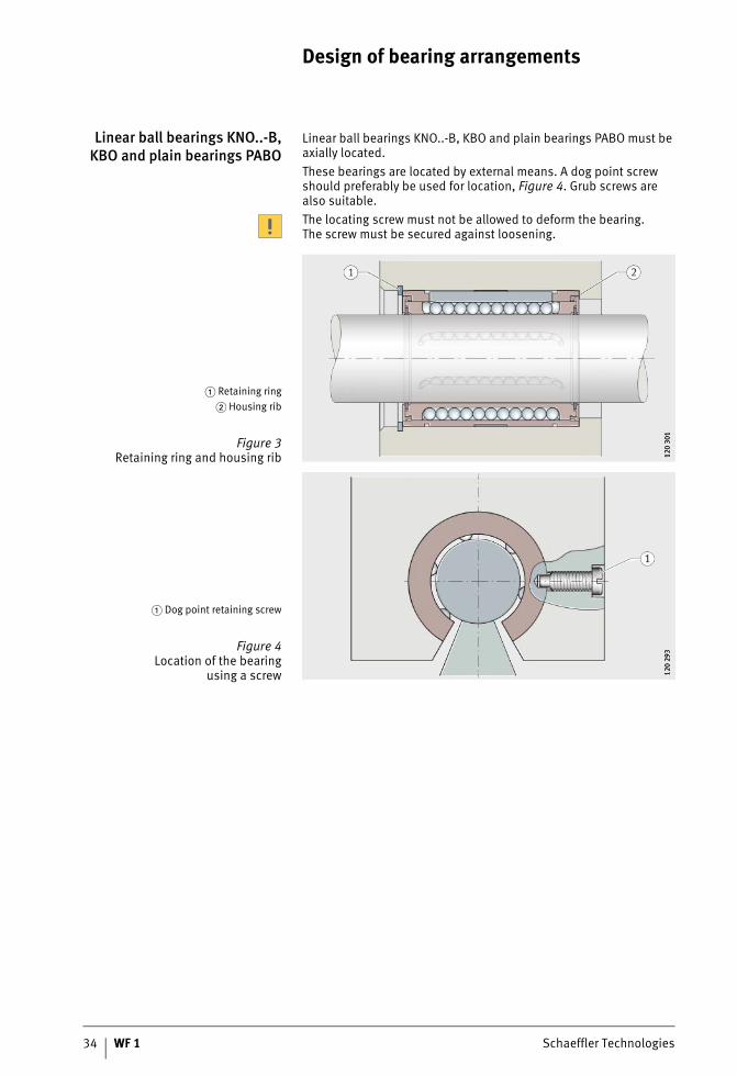
Linear ball bearings KNO..-B, KBO and plain bearings PABO must be axially located.These bearings are located by external means. A dog point screw should preferably be used for location, Figure 4. Grub screws are also suitable.The locating screw must not be allowed to deform the bearing.The screw must be secured against loosening.
� Retaining ring� Housing rib
Figure 3Retaining ring and housing rib 12
0 30
112
0 30
1
� Dog point retaining screw
Figure 4Location of the bearing
using a screw 120
293
120
293

Schaeffler Technologies WF 1 35
Linear ball bearing andhousing units
Linear ball bearing and housing units and linear plain bearing units are screw mounted into or through the fixing holes, Figure 5 and Figure 6.Location of the units by means of dowels is only necessary in rare cases, but can be achieved easily by drilling out the centring holes.
� Bottom view
Figure 5Location of a unit from below 12
0 30
212
0 30
2
� Top view
Figure 6Location of a unit from above 00
019C
2500
019C
25
36 WF 1 Schaeffler Technologies
Design of bearing arrangements
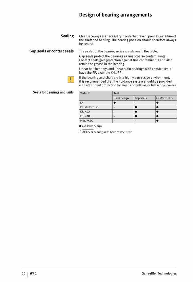
Sealing Clean raceways are necessary in order to prevent premature failure of the shaft and bearing. The bearing position should therefore always be sealed.
Gap seals or contact seals The seals for the bearing series are shown in the table.Gap seals protect the bearings against coarse contaminants.Contact seals give protection against fine contaminants and also retain the grease in the bearing.Linear ball bearings and linear plain bearings with contact seals have the PP, example KH..-PP.If the bearing and shaft are in a highly aggressive environment,it is recommended that the guidance system should be provided with additional protection by means of bellows or telescopic covers.
Seals for bearings and units
● Available design.
1) All linear bearing units have contact seals.
Series1) Seal
Open design Gap seals Contact seals
KH ● – ●
KN..-B, KNO..-B – ● ●
KS, KSO – ● ●
KB, KBO – ● ●
PAB, PABO – – ●
Schaeffler Technologies WF 1 37
Operating clearance
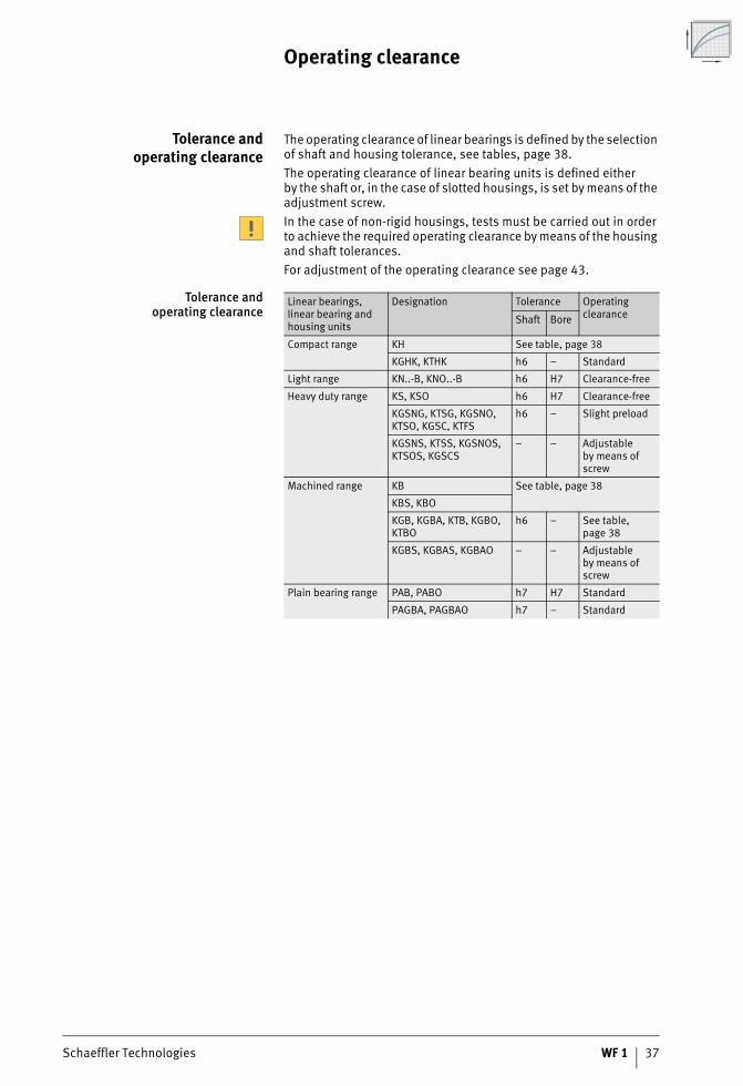
Tolerance andoperating clearance
The operating clearance of linear bearings is defined by the selection of shaft and housing tolerance, see tables, page 38.The operating clearance of linear bearing units is defined eitherby the shaft or, in the case of slotted housings, is set by means of the adjustment screw.In the case of non-rigid housings, tests must be carried out in order to achieve the required operating clearance by means of the housing and shaft tolerances.For adjustment of the operating clearance see page 43.
Tolerance andoperating clearance
Linear bearings, linear bearing and housing units
Designation Tolerance Operating clearanceShaft Bore
Compact range KH See table, page 38
KGHK, KTHK h6 – Standard
Light range KN..-B, KNO..-B h6 H7 Clearance-free
Heavy duty range KS, KSO h6 H7 Clearance-free
KGSNG, KTSG, KGSNO, KTSO, KGSC, KTFS
h6 – Slight preload
KGSNS, KTSS, KGSNOS, KTSOS, KGSCS
– – Adjustableby means of screw
Machined range KB See table, page 38
KBS, KBO
KGB, KGBA, KTB, KGBO, KTBO
h6 – See table, page 38
KGBS, KGBAS, KGBAO – – Adjustableby means of screw
Plain bearing range PAB, PABO h7 H7 Standard
PAGBA, PAGBAO h7 – Standard
38 WF 1 Schaeffler Technologies
Operating clearance
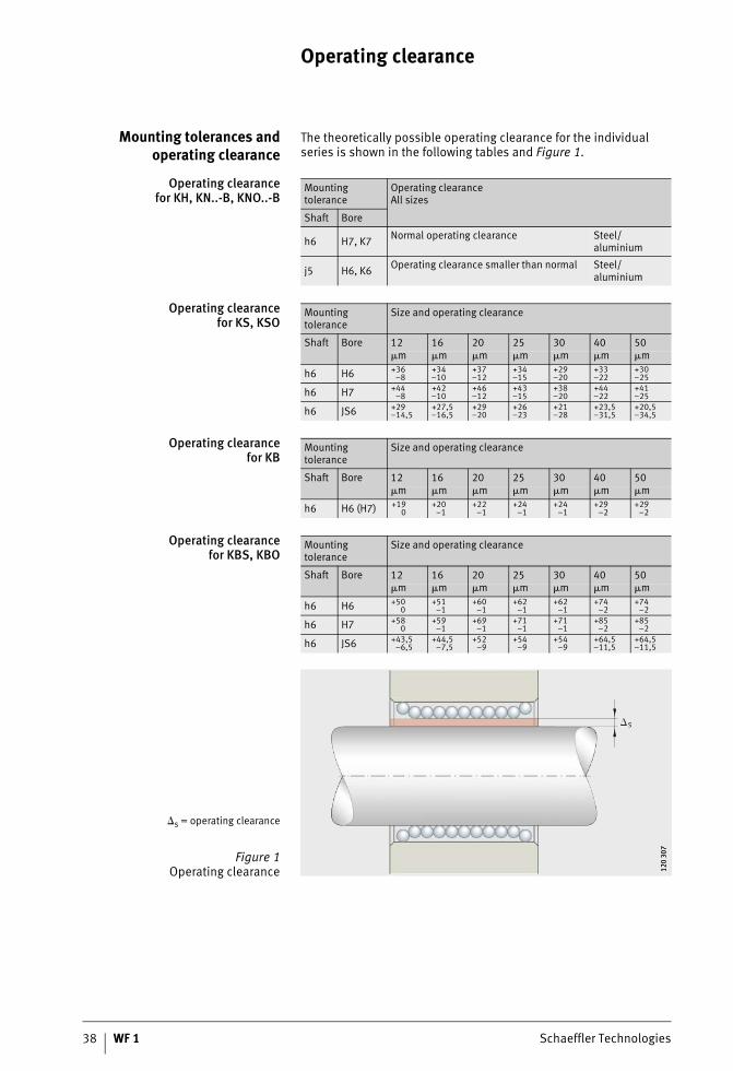
Mounting tolerances andoperating clearance
The theoretically possible operating clearance for the individual series is shown in the following tables and Figure 1.
Operating clearancefor KH, KN..-B, KNO..-B
Operating clearancefor KS, KSO
Operating clearancefor KB
Operating clearancefor KBS, KBO
Mounting tolerance
Operating clearanceAll sizes
Shaft Bore
h6 H7, K7 Normal operating clearance Steel/aluminium
j5 H6, K6 Operating clearance smaller than normal Steel/aluminium
Mounting tolerance
Size and operating clearance
Shaft Bore 12 16 20 25 30 40 50m m m m m m m
h6 H6 +36–8
+34–10
+37–12
+34–15
+29–20
+33–22
+30–25
h6 H7 +44–8
+42–10
+46–12
+43–15
+38–20
+44–22
+41–25
h6 JS6 +29–14,5
+27,5–16,5
+29–20
+26–23
+21–28
+23,5–31,5
+20,5–34,5
Mounting tolerance
Size and operating clearance
Shaft Bore 12 16 20 25 30 40 50m m m m m m m
h6 H6 (H7) +190
+20–1
+22–1
+24–1
+24–1
+29–2
+29–2
Mounting tolerance
Size and operating clearance
Shaft Bore 12 16 20 25 30 40 50m m m m m m m
h6 H6 +500
+51–1
+60–1
+62–1
+62–1
+74–2
+74–2
h6 H7 +580
+59–1
+69–1
+71–1
+71–1
+85–2
+85–2
h6 JS6 +43,5–6,5
+44,5–7,5
+52–9
+54–9
+54–9
+64,5–11,5
+64,5–11,5
s = operating clearance
Figure 1Operating clearance 12
0 30
712
0 30
7
Schaeffler Technologies WF 1 39
Mounting
The bearings should only be removed from their packaging immediately before mounting. Bearings with dry preservative should be protected against corrosion immediately after removal fromthe packaging.The mounting area and the adjacent construction must be clean. Contamination impairs the accuracy and operating life of the guidance systems.The bearings must not be tilted.In the case of sealed bearings with a segment cutout, it mustbe ensured at all costs that the ends of the seal lips are not turned inside out (pay attention to the packing slip).
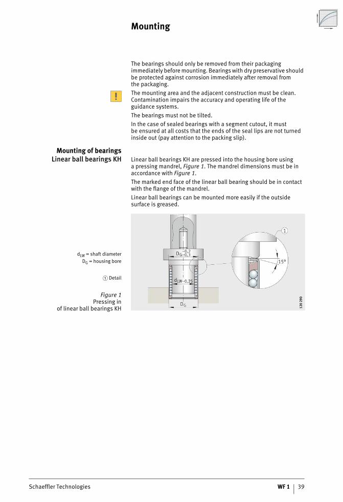
Mounting of bearingsLinear ball bearings KH Linear ball bearings KH are pressed into the housing bore using
a pressing mandrel, Figure 1. The mandrel dimensions must be in accordance with Figure 1.The marked end face of the linear ball bearing should be in contact with the flange of the mandrel.Linear ball bearings can be mounted more easily if the outside surface is greased.
dLW = shaft diameterDG = housing bore
� Detail
Figure 1Pressing in
of linear ball bearings KH 120
290
120
290
40 WF 1 Schaeffler Technologies
Mounting
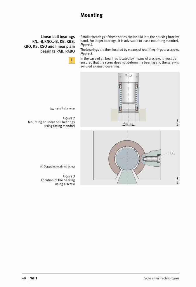
Linear ball bearingsKN..-B,KNO..-B, KB, KBS,
KBO, KS, KSO and linear plainbearings PAB, PABO
Smaller bearings of these series can be slid into the housing bore by hand. For larger bearings, it is advisable to use a mounting mandrel, Figure 2.The bearings are then located by means of retaining rings or a screw, Figure 3.In the case of all bearings located by means of a screw, it must be ensured that the screw does not deform the bearing and the screw is secured against loosening.
dLW = shaft diameter
Figure 2Mounting of linear ball bearings
using fitting mandrel 120
291
120
291
� Dog point retaining screw
Figure 3Location of the bearing
using a screw 120
293
120
293
Schaeffler Technologies WF 1 41
Alignmentof bearings and shafts
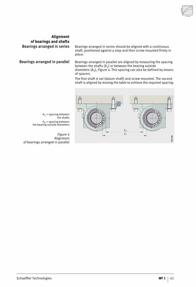
Bearings arranged in series Bearings arranged in series should be aligned with a continuous shaft, positioned against a stop and then screw mounted firmly in place.
Bearings arranged in parallel Bearings arranged in parallel are aligned by measuring the spacing between the shafts (A1) or between the bearing outside diameters (A2), Figure 4. This spacing can also be defined by means of spacers.The first shaft is set (datum shaft) and screw mounted. The second shaft is aligned by moving the table to achieve the required spacing.
A1 = spacing betweenthe shafts
A2 = spacing betweenthe bearing outside diameters
Figure 4Alignment
of bearings arranged in parallel 120
294
120
294
42 WF 1 Schaeffler Technologies
Mounting
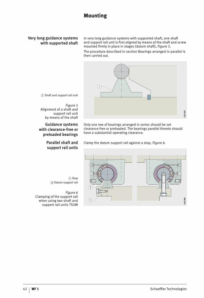
Very long guidance systemswith supported shaft
In very long guidance systems with supported shaft, one shaftand support rail unit is first aligned by means of the shaft and screw mounted firmly in place in stages (datum shaft), Figure 5.The procedure described in section Bearings arranged in parallel is then carried out.
Guidance systemswith clearance-free or
preloaded bearings
Only one row of bearings arranged in series should be set clearance-free or preloaded. The bearings parallel thereto should have a substantial operating clearance.
Parallel shaft andsupport rail units
Clamp the datum support rail against a stop, Figure 6.
� Shaft and support rail unit
Figure 5Alignment of a shaft and
support rail unitby means of the shaft 12
0 29
512
0 29
5
� Stop� Datum support rail
Figure 6Clamping of the support rail
when using two shaft andsupport rail units TSUW 12
0 29
612
0 29
6
Schaeffler Technologies WF 1 43
Settingthe operating clearance
Settingbearings clearance-free
In the case of linear ball bearings KBS and slotted housings,the operating clearance can be adjusted. The screw must be adjusted until resistance to further rotation can be felt betweenthe shaft and bearing.The adjusted bearing should not be rotated any further on the shaft.
Setting the preload Preloaded bearings are set clearance-free on a master shaft thatis smaller than the actual shaft in the application by the amountof the preload dimension.
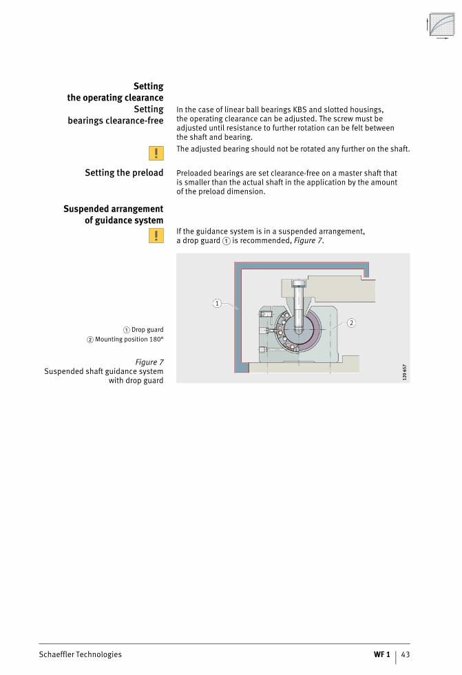
Suspended arrangementof guidance system
If the guidance system is in a suspended arrangement,a drop guard � is recommended, Figure 7.
� Drop guard� Mounting position 180°
Figure 7Suspended shaft guidance system
with drop guard 120
657
120
657
Linear bearings andlinear bearing and housing unitsCompact rangeLight rangeHeavy duty rangeMachined rangePlain bearing range
Schaeffler Technologies WF 1 45
Page
Linear bearings and linear bearing and housing units
Matrix Matrix for preselectionof linear bearings and linear bearing and housing units........... 46
Product overview Linear bearings and linear bearing and housing units.............. 48Compact range................................................................... 48Light range......................................................................... 48Heavy duty range ............................................................... 49Machined range ................................................................. 50Plain bearing range ............................................................ 51
Features Linear bearings....................................................................... 52
Linear bearing and housing units ............................................ 53
Sealing................................................................................... 54
Lubrication............................................................................. 55
Operating temperature ........................................................... 55
Operating limits...................................................................... 55
Suffixes.................................................................................. 55
Compact range ....................................................................... 56
Light range ............................................................................. 58
Heavy duty range.................................................................... 60
Machined range ..................................................................... 62
Plain bearing range................................................................. 64
Dimension tables Compact range, linear ball bearings ........................................ 67
Compact range, linear ball bearing and housing units ............. 68
Light range, linear ball bearings.............................................. 74
Heavy duty range, linear ball bearings..................................... 76
Heavy duty range, linear ball bearing and housing units .......... 78
Machined range, linear ball bearings ...................................... 90
Machined range, linear ball bearing and housing units............ 92
Plain bearing range, linear plain bearings ............................... 100
Plain bearing range,linear plain bearing and housing units .................................... 102
46 WF 1 Schaeffler Technologies
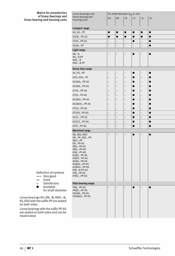
Matrix for preselectionof linear bearings and
linear bearing and housing units
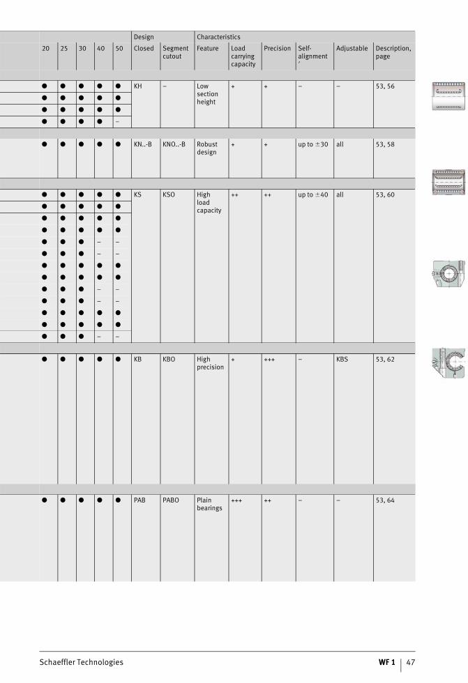
Definition of symbols+++ Very good++ Good+ Satisfactory● Available
for shaft diameter
Linear bearings KH, KN..-B, KNO..-B, KS, KSO with the suffix PP are sealed on both sides.Linear bearings with the suffix PP-AS are sealed on both sides and can be relubricated.
Linear bearings andlinear bearing andhousing units
For shaft diameter dLW in mm
06 08 10 12 14 16
Compact rangeKH, KH..-PP ● ● ● ● ● ●
KGHK..-PP-AS ● ● ● ● ● ●
KTHK..-PP-AS – – – ● – ●
KGHA..-PP – – – – – ●
Light rangeKN..-BKN..-B-PPKNO..-BKNO..-B-PP
– – – ● – ●
Heavy duty rangeKS, KS..-PP – – – ● – ●
KSO, KSO..-PP – – – ● – ●
KGSNG..-PP-AS – – – ● – ●
KGSNS..-PP-AS – – – ● – ●
KTSG..-PP-AS – – – ● – ●
KTSS..-PP-AS – – – ● – ●
KGSNO..-PP-AS – – – ● – ●
KGSNOS..-PP-AS – – – ● – ●
KTSO..-PP-AS – – – ● – ●
KTSOS..-PP-AS – – – ● – ●
KGSC..-PP-AS – – – ● – ●
KGSCS..-PP-AS – – – ● – ●
KTFS..-PP-AS – – – ● – ●
Machined rangeKB, KBS, KBOKB..-PP, KBS..-PPKBO..-PPKB..-PP-ASKBS..-PP-ASKBO..-PP-ASKGB..-PP-ASKGBS..-PP-ASKGBO..-PP-ASKGBA..-PP-ASKGBAS..-PP-ASKGBAO..-PP-ASKFB..-B-PP-ASKTB..-PP-ASKTBO..-PP-AS
– – – ● – ●
Plain bearing rangePAB..-PP-ASPABO..-PP-ASPAGBA..-PP-ASPAGBAO..-PP-AS
– – – ● – ●
Schaeffler Technologies WF 1 47
Design Characteristics
20 25 30 40 50 Closed Segment cutout
Feature Load carrying capacity
Precision Self-alignment�
Adjustable Description, page
● ● ● ● ● KH – Lowsection height
+ + – – 53, 56
● ● ● ● ●
● ● ● ● ●
● ● ● ● –
● ● ● ● ● KN..-B KNO..-B Robust design
+ + up to �30 all 53, 58
● ● ● ● ● KS KSO Highload capacity
++ ++ up to �40 all 53, 60
● ● ● ● ●
● ● ● ● ●
● ● ● ● ●
● ● ● – –
● ● ● – –
● ● ● ● ●
● ● ● ● ●
● ● ● – –
● ● ● – –
● ● ● ● ●
● ● ● ● ●
● ● ● – –
● ● ● ● ● KB KBO High precision
+ +++ – KBS 53, 62
● ● ● ● ● PAB PABO Plain bearings
+++ ++ – – 53, 64
48 WF 1 Schaeffler Technologies
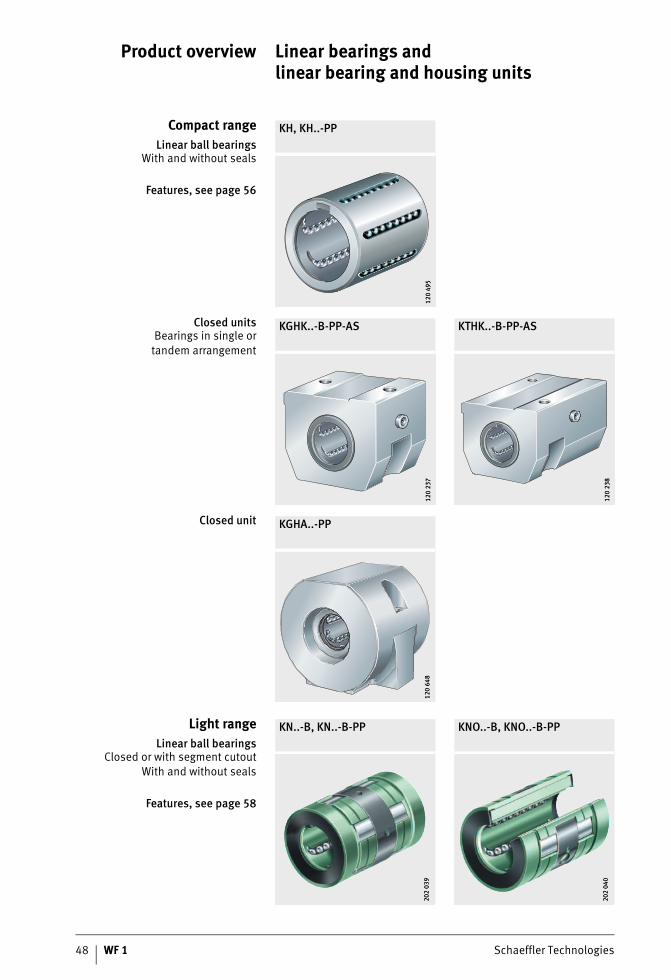
Product overview Linear bearings and linear bearing and housing units
Compact rangeLinear ball bearings
With and without seals
Features, see page 56
KH, KH..-PP
120
495
120
495
Closed unitsBearings in single or
tandem arrangement
KGHK..-B-PP-AS KTHK..-B-PP-AS
120
237
120
237
120
238
120
238
Closed unit KGHA..-PP
120
648
120
648
Light rangeLinear ball bearings
Closed or with segment cutoutWith and without seals
Features, see page 58
KN..-B, KN..-B-PP KNO..-B, KNO..-B-PP
202
039
202
039
202
040
202
040
Schaeffler Technologies WF 1 49
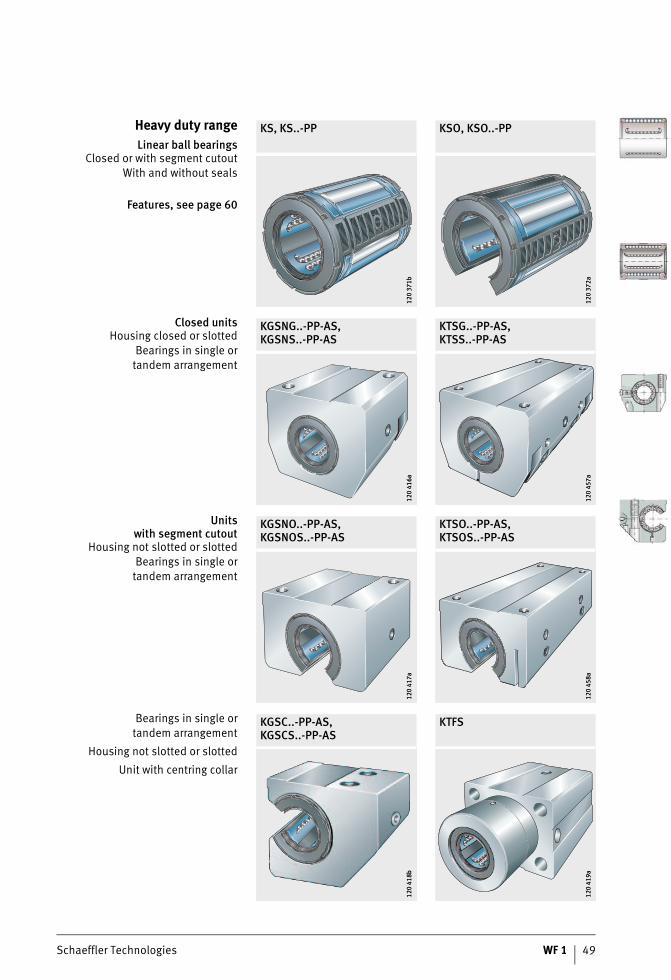
Heavy duty rangeLinear ball bearings
Closed or with segment cutoutWith and without seals
Features, see page 60
KS, KS..-PP KSO, KSO..-PP
120
371b
120
371b
120
372a
120
372a
Closed unitsHousing closed or slotted
Bearings in single ortandem arrangement
KGSNG..-PP-AS,KGSNS..-PP-AS
KTSG..-PP-AS,KTSS..-PP-AS
120
416a
120
416a
120
457a
120
457a
Unitswith segment cutout
Housing not slotted or slottedBearings in single or
tandem arrangement
KGSNO..-PP-AS,KGSNOS..-PP-AS
KTSO..-PP-AS,KTSOS..-PP-AS
120
417a
120
417a
120
458a
120
458a
Bearings in single ortandem arrangement
Housing not slotted or slotted
Unit with centring collar
KGSC..-PP-AS,KGSCS..-PP-AS
KTFS
120
418b
120
418b
120
419a
120
419a
Linear bearings and linear bearing and housing units
50 WF 1 Schaeffler Technologies
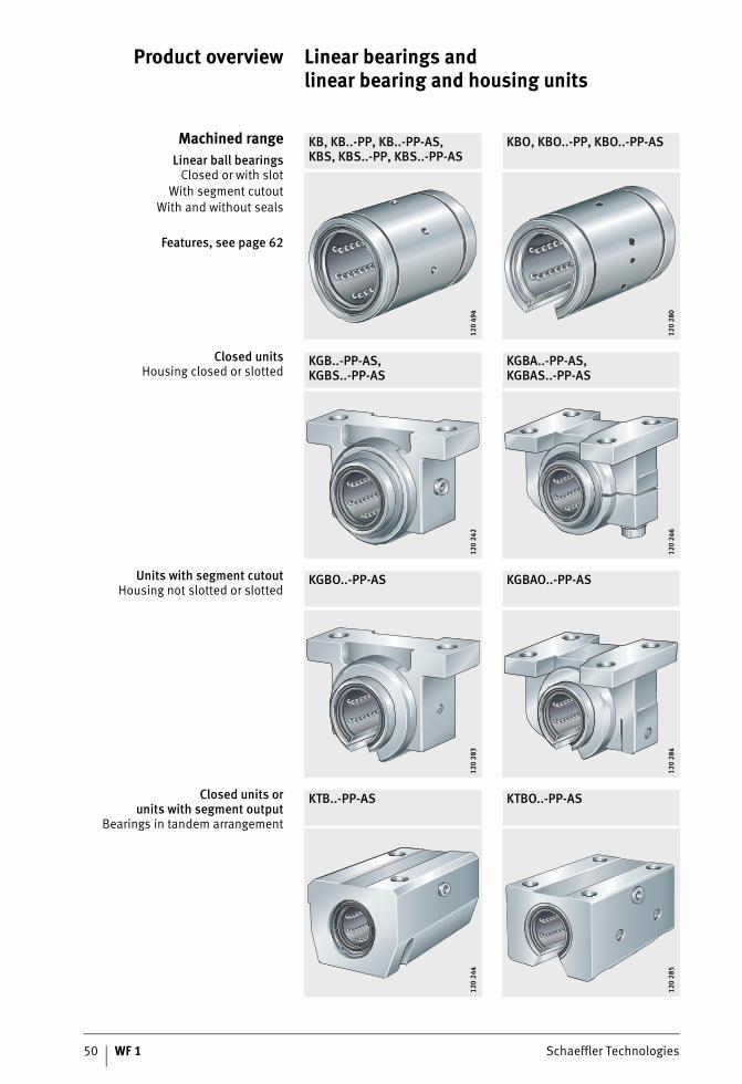
Product overview
Machined rangeLinear ball bearings
Closed or with slotWith segment cutout
With and without seals
Features, see page 62
KB, KB..-PP, KB..-PP-AS,KBS, KBS..-PP, KBS..-PP-AS
KBO, KBO..-PP, KBO..-PP-AS
120
494
120
494
120
280
120
280
Closed unitsHousing closed or slotted
KGB..-PP-AS,KGBS..-PP-AS
KGBA..-PP-AS,KGBAS..-PP-AS
120
242
120
242
120
246
120
246
Units with segment cutoutHousing not slotted or slotted
KGBO..-PP-AS KGBAO..-PP-AS
120
283
120
283
120
284
120
284
Closed units orunits with segment output
Bearings in tandem arrangement
KTB..-PP-AS KTBO..-PP-AS
120
244
120
244
120
285
120
285
Schaeffler Technologies WF 1 51
Closed unitHousing with flange
KFB..-B-PP-AS
0001
9FE0
0001
9FE0
Plain bearing rangeLinear plain bearings
Closed or with segment cutoutSealed
Features, see page 64
PAB..-PP-AS PABO..-PP-AS
136
268
136
268
136
496
136
496
Linear plain bearing andhousing units
Closed or with segment cutout
PAGBA..-PP-AS PAGBAO..-PP-AS
136
236
136
236
136
237
136
237
52 WF 1 Schaeffler Technologies
Linear bearings and linear bearing and housing units
Features Linear bearings and linear bearing and housing units are availablein the compact, light, heavy duty, machined and plain bearing range. The bearings can support high loads while having a relativelylow mass and allow the construction of linear guidance systemswith unlimited travel.Each series has highly specific characteristics that preciselydefine it as suitable for particular applications. These may include,for example, requirements for compensation of misalignments,low-friction running, high accelerations and travel velocities or long operating life.The range, which has been constructed and expanded in accordance with a modular concept, provides the best technical and economic solution, in relation to each application, for bearing arrangements with shaft guidance systems.
Linear bearings Linear ball bearings and linear plain bearings are available in open or closed designs. The open design has a segment cut out and is intended for supported shafts. Several series allow, in conjunction with the corresponding housings, adjustment of the radial clearance in order to achieve clearance-free or preloaded guidance systems.
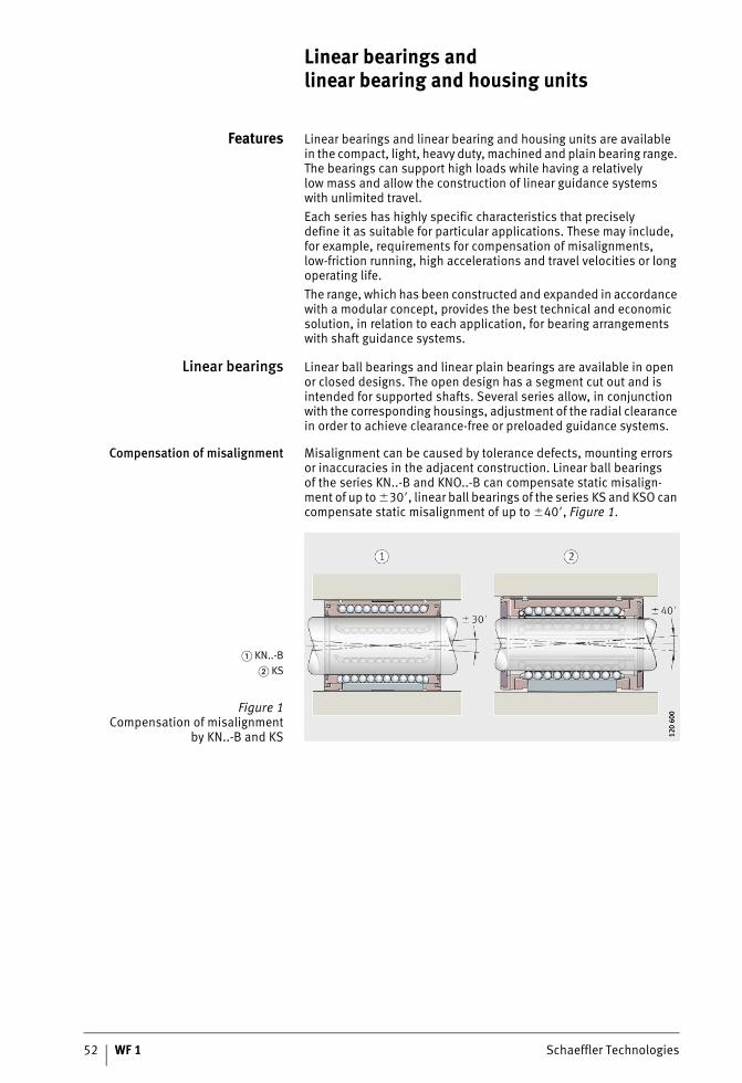
Compensation of misalignment Misalignment can be caused by tolerance defects, mounting errors or inaccuracies in the adjacent construction. Linear ball bearingsof the series KN..-B and KNO..-B can compensate static misalign-ment of up to �30�, linear ball bearings of the series KS and KSO can compensate static misalignment of up to �40�, Figure 1.
� KN..-B� KS
Figure 1Compensation of misalignment
by KN..-B and KS 120
600
120
600
Schaeffler Technologies WF 1 53
Due to the self-alignment function, the balls run without difficulty into the load zone. At the same time, the load distributionover the whole ball row is more uniform. This leads to smoother running, allows higher accelerations and prevents overloadingof the individual balls.Overall, this means that the bearings can achieve higher loads anda longer operating life; if necessary, the adjacent construction can be designed to be smaller and more economical.In order to fully utilise the basic load ratings given in the dimension table, the shaft raceway must be hardened (670 HV + 165 HV) and ground. The indications in section Design of bearing arrangements must be observed, page 33.
Linear bearing andhousing units
Linear ball bearings and plain bearings are also available in conjunc-tion with INA housings as complete bearing units. The linear bearing is located in the housing by means of a radial fixing screw to prevent axial displacement.The housings are made from a high rigidity, high strength aluminium alloy that allows the full load carrying capacity of the bearings fitted to be utilised. In the machined series, pressure diecast housings are also available.Due to the comparatively low total mass, the units are particularly suitable for reduced mass designs with high loads and where higher accelerations and travel velocities are required.
Simple location Threaded or counterbored holes in the housing allow straightforward screw mounting on the adjacent construction, if necessary from below.For rapid alignment, the housings have a locating edge. This also prevents distortion of the linear bearings when the housings are being mounted.Centring holes allow rapid additional location of the housings by dowels on the adjacent construction.
54 WF 1 Schaeffler Technologies
Linear bearings and linear bearing and housing units
Housing designs The housings are available in closed design, with a segmentcutout and in open, slotted and tandem versions (with and withouta centring collar).
Closed design In this variant, the bearings and housings are closed.As a result, high precision standard guidance systems with a fixed enveloping circle can be easily achieved.
With segment cutout Open designs with a segment cutout are used where,in the case of long guidance systems, the shaft must be supported and the bearing arrangement must be highly rigid.
Slotted design Closed designs and designs with a segment cutout are alsoavailable in several series with a slot. Slotted variants are suitable for clearance-free or preloaded guidance systems.The operating clearance is set by means of an adjusting screw.
Tandem design The tandem version contains two linear bearings.As a result, the units have particularly high load carrying capacity.Tandem ball bearing and housing units are available in open and closed designs. Both variants are also available in the named design with a slot.
With centring collar For special applications, there is also a tandem versionwith a centring collar for locating bores to H7.
Highly cost-effective As a result of volume production in large quantities, the complete units are normally considerably more economical than customers’ own designs.
Sealing The bearings are available in an open version and with contact seals on both sides (suffix PP). The linear bearings of type KH, KN..-B and KB have seals with two seal lips on their end faces; the outer lip prevents the ingress of contamination, the inner lip retains the lubri-cant in the bearing. The linear bearings of type KS have contact seals with one seal lip.
Schaeffler Technologies WF 1 55
Lubrication Due to the initial greasing with a high quality grease and the integral lubricant reservoir, the linear bearings are maintenance-free for many applications; if necessary, however, they can be relubricated.Linear ball bearings can be lubricated, depending on the design, via the openings in the outer ring or radial holes arranged in the centre of the bearing.In the units, lubrication is carried out via a separate lubrication nipple in the housing; location of the bearing in the housing andthe relubrication devices are thus separate from each other.
Operating temperature The bearings and housings can be used at operating temperatures from –30 °C to +80 °C.
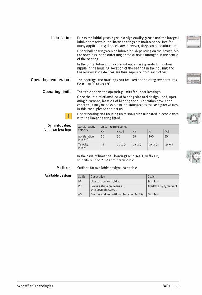
Operating limits The table shows the operating limits for linear bearings.Once the interrelationships of bearing size and design, load, oper-ating clearance, location of bearings and lubrication have been checked, it may be possible in individual cases to use higher values. In this case, please contact us.Linear bearing and housing units should be allocated in accordance with the linear bearing fitted.
Dynamic valuesfor linear bearings
In the case of linear ball bearings with seals, suffix PP,velocities up to 2 m/s are permissible.
Suffixes Suffixes for available designs: see table.
Available designs
Acceleration,velocity
Linear bearing series
KH KN..-B KB KS PAB
Accelerationin m/s2
50 50 50 100 50
Velocityin m/s
2 up to 5 up to 5 up to 5 up to 3
Suffix Description Design
PP Lip seals on both sides Standard
PPL Sealing strips on bearingswith segment cutout
Available by agreement
AS Bearing and unit with relubrication facility Standard
56 WF 1 Schaeffler Technologies
Linear bearings and linear bearing and housing units
Compact range Linear ball bearings KH and linear ball bearing and housing unitsof the compact range have a small radial design envelope and are particularly economical. Their low section height automatically makes them attractive for applications in which only a small amount of radial space is available.Due to the closed design, they are suitable for use on shafts.
Linear ball bearings The bearings have an outer ring with openings. This contains a ball and cage assembly with a plastic cage. The outer ring is formed and hardened. The balls undergo return travel along the openings in the outer ring.
Seals The bearings are available in an open version and with lip sealson both sides (suffix PP). The end face seals have two seal lips;the outer lip prevents the ingress of contamination, the inner lip retains the lubricant in the bearing.
Linear ball bearing andhousing units
Linear ball bearing and housing units of the compact range are available with one integral bearing and, in the tandem versionwith particularly high load carrying capacity, with two bearings.The housings are made from high strength aluminium.
Anti-corrosion protection The housings are two-piece components made from sheet steelwith a Corrotect® coating. The bearings and housing parts are packed separately. The bearing is firmly seated once it is mountedin the housing.
Further information Further information is given on the following pages:■ dimension tables, see page 67■ shafts, see page 104■ shaft and support rail units, see page 128■ accessories, see page 144.
Schaeffler Technologies WF 1 57
Linear ball bearings andlinear ball bearing and
housing units, compact range
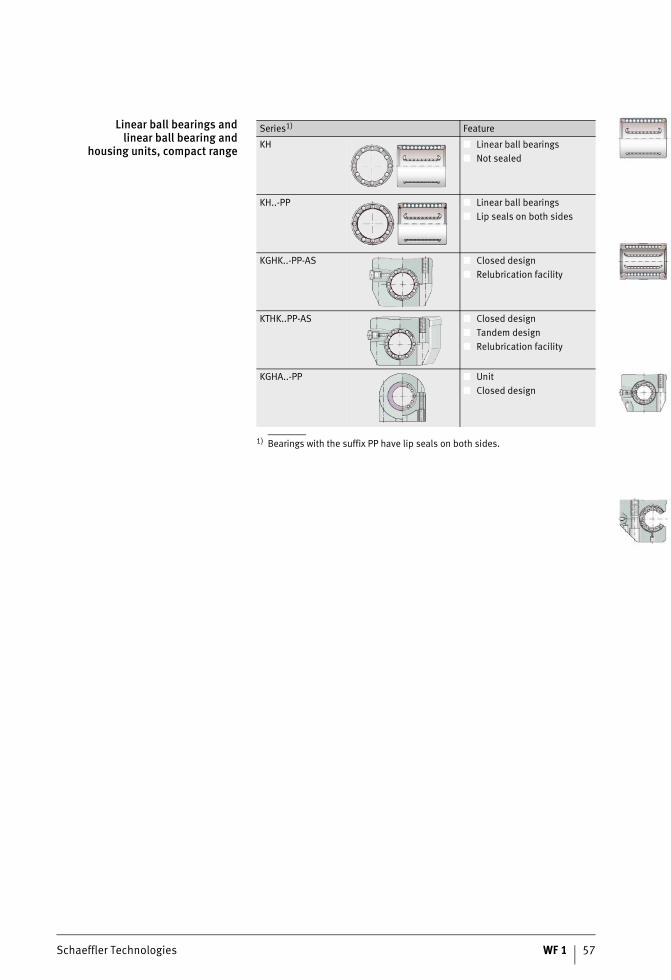
1) Bearings with the suffix PP have lip seals on both sides.
Series1) Feature
KH ■ Linear ball bearings■ Not sealed
KH..-PP ■ Linear ball bearings■ Lip seals on both sides
KGHK..-PP-AS ■ Closed design■ Relubrication facility
KTHK..PP-AS ■ Closed design■ Tandem design■ Relubrication facility
KGHA..-PP ■ Unit■ Closed design
58 WF 1 Schaeffler Technologies
Linear bearings and linear bearing and housing units
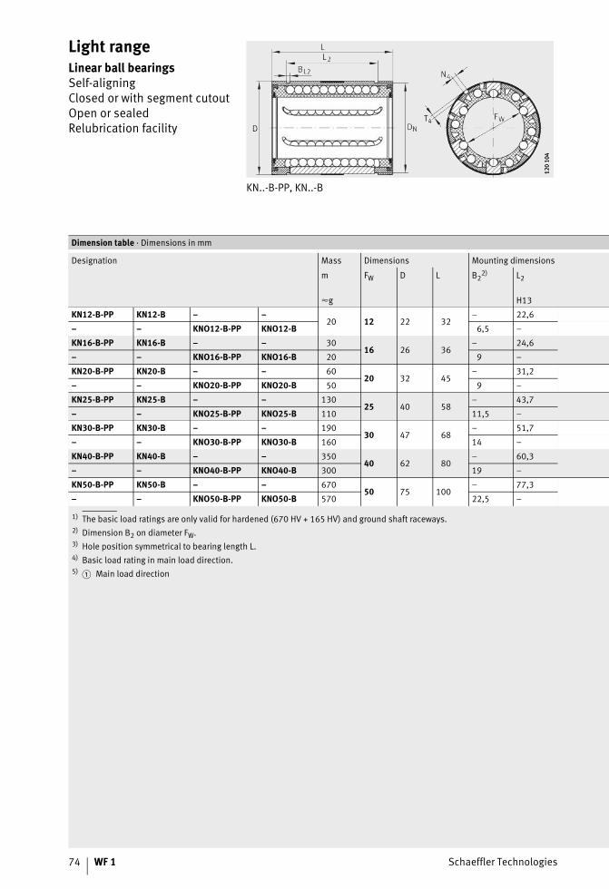
Light range The light range is available as linear ball bearings KN..-B of a closed design and as linear ball bearings KNO..-B with a segment cutout.In order to compensate misalignments arising from manufacturing tolerances, mounting errors and shaft deflection, the linear bearings of series KN..-B are self-aligning up to �30�.Their robust construction allows operation even under aggressive operating conditions.The series KN..-B is of a closed construction and is designed for use on shafts. KNO..-B has a segment cutout and is used with shaft and support rail units.
Linear ball bearings Linear ball bearings KN..-B and KNO..-B comprise a plastic cage with inserted raceway plates. The plates are supported in the housing bore by means of a retaining ring. Due to the retaining ring, the plates can “rock” and thus compensate for static misalignments.
Seals The bearings are available in an open version and with lip sealson both sides (suffix PP). The end face seals have two seal lips;the outer lip prevents the ingress of contamination, the inner lip retains the lubricant in the bearing.
Further information Further information is given on the following pages:■ dimension tables, see page 74■ shafts, see page 104■ shaft and support rail units, see page 128■ accessories, see page 144.
Schaeffler Technologies WF 1 59
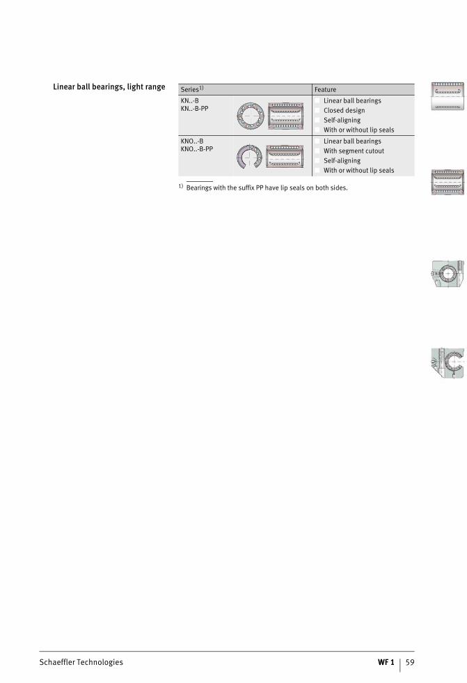
Linear ball bearings, light range
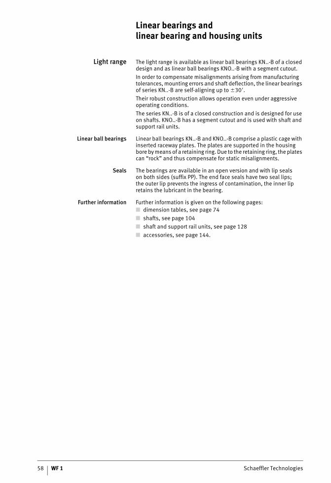
1) Bearings with the suffix PP have lip seals on both sides.
Series1) Feature
KN..-BKN..-B-PP
■ Linear ball bearings■ Closed design■ Self-aligning■ With or without lip seals
KNO..-BKNO..-B-PP
■ Linear ball bearings■ With segment cutout■ Self-aligning■ With or without lip seals
60 WF 1 Schaeffler Technologies
Linear bearings and linear bearing and housing units
Heavy duty range Linear ball bearings of the heavy duty range KS and KSO andthe corresponding ball bearing and housing units have particularly high load carrying capacity and have an angular adjustment facility for compensation of misalignments. They have very good running characteristics.
Linear ball bearings Linear ball bearings KS and KSO comprise a plastic cage with loosely retained segments. The double row segments with crowned raceway plates can realign themselves in all directions and thus compensate misalignments. Since the complete segment undergoes realignment, there is no disruption to the recirculation of the balls.This results in uniformly low displacement resistance.The series KS is of a closed construction and is designed for useon shafts. KSO has a segment cutout and is used in conjunctionwith shaft and support rail units.
Seals The bearings are available with contact seals or gap seals.The contact seals on the end faces have two seal lips;the outer lip prevents the ingress of contamination, the inner lip retains the lubricant in the bearing.
Linear ball bearing andhousing units
Linear ball bearing and housing units of the heavy duty range are available with one integral bearing and, in the tandem versionwith particularly high load carrying capacity, with two bearings.The housings are made from high strength aluminium.The housings are available in a closed design, with a segment cutout for supported shafts and with or without a slot. In designs with a slot, the radial clearance can be adjusted by means of an adjusting screw.All series have a locating edge and centring holes for dowel holes.The bearings are sealed on both sides, they have an initial greasing and can be relubricated via a lubrication nipple in the housing.
Further information Further information is given on the following pages:■ dimension tables, see page 76■ shafts, see page 104■ shaft and support rail units, see page 128■ accessories, see page 144.
Schaeffler Technologies WF 1 61
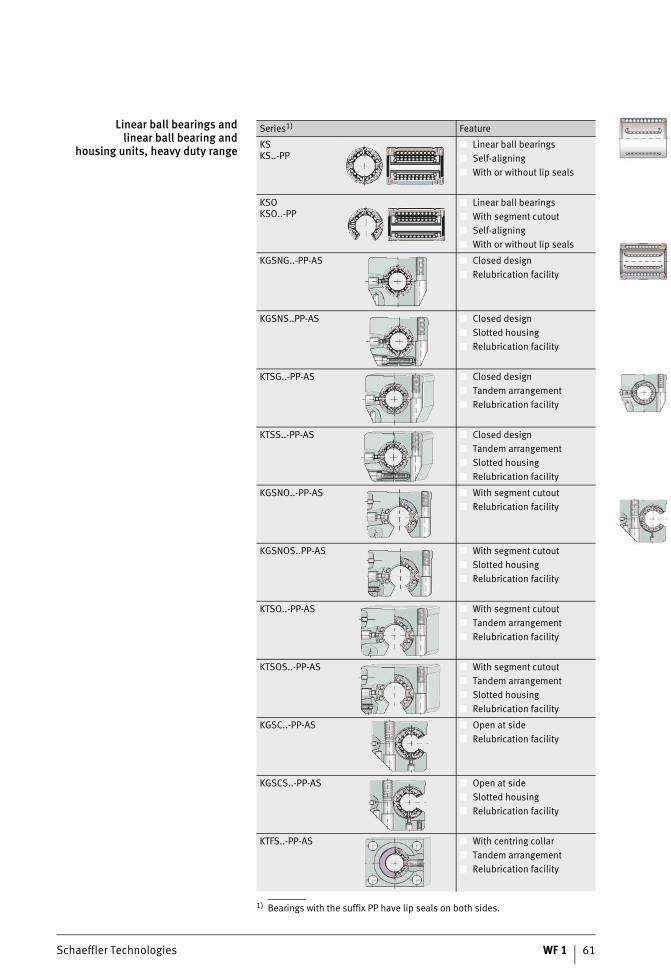
Linear ball bearings andlinear ball bearing and
housing units, heavy duty range
1) Bearings with the suffix PP have lip seals on both sides.
Series1) Feature
KSKS..-PP
■ Linear ball bearings■ Self-aligning■ With or without lip seals
KSOKSO..-PP
■ Linear ball bearings■ With segment cutout■ Self-aligning■ With or without lip seals
KGSNG..-PP-AS ■ Closed design■ Relubrication facility
KGSNS..PP-AS ■ Closed design■ Slotted housing■ Relubrication facility
KTSG..-PP-AS ■ Closed design■ Tandem arrangement■ Relubrication facility
KTSS..-PP-AS ■ Closed design■ Tandem arrangement■ Slotted housing■ Relubrication facility
KGSNO..-PP-AS ■ With segment cutout■ Relubrication facility
KGSNOS..PP-AS ■ With segment cutout■ Slotted housing■ Relubrication facility
KTSO..-PP-AS ■ With segment cutout■ Tandem arrangement■ Relubrication facility
KTSOS..-PP-AS ■ With segment cutout■ Tandem arrangement■ Slotted housing■ Relubrication facility
KGSC..-PP-AS ■ Open at side■ Relubrication facility
KGSCS..-PP-AS ■ Open at side■ Slotted housing■ Relubrication facility
KTFS..-PP-AS ■ With centring collar■ Tandem arrangement■ Relubrication facility

62 WF 1 Schaeffler Technologies
Linear bearings and linear bearing and housing units
Machined range Linear ball bearings of the machined range KB, KBS and KBO andthe corresponding linear ball bearing and housing units arehigh precision and particularly rigid. They have excellent running characteristics.
Linear ball bearings Linear ball bearings KB, KBS and KBO comprise a hardened and ground outer ring in which a ball and cage assembly with a plastic cage is integrated.The balls are guided with high precision throughout the return area by a special spring washer. This ensures that the displacement resistance remains uniformly low even under difficult operating conditions and irrespective of the mounting position.The series KB is of a closed construction and is designed for useon shafts. KBO has a segment cutout and is used in conjunctionwith shaft and support rail units. KBS has a slot for adjustment ofthe radial clearance.
Seals The bearings have contact seals or gap seals.
Linear ball bearing andhousing units
Linear ball bearing and housing units of the machined range are available with one integral bearing and, in the tandem versionwith particularly high load carrying capacity, with two bearings.The housings are made from high strength aluminium or are pressure diecast.The housings are available in a closed design, with a segment cutout for supported shafts and with or without a slot. In designs with a slot, the radial clearance can be adjusted by means of an adjusting screw.All series have a locating edge and centring holes for dowel holes.The bearings are sealed on both sides, they have an initial greasing and can be relubricated via a lubrication nipple in the housing.
Further information Further information is given on the following pages:■ dimension tables, see page 90■ shafts, see page 104■ shaft and support rail units, see page 128■ accessories, see page 144.
Schaeffler Technologies WF 1 63
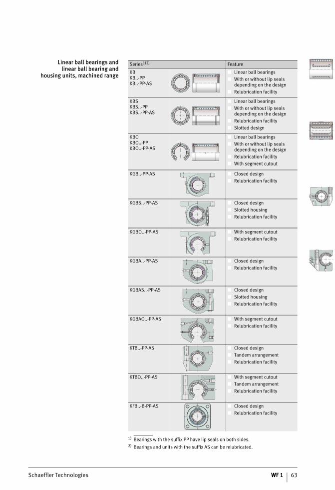
Linear ball bearings andlinear ball bearing and
housing units, machined range
1) Bearings with the suffix PP have lip seals on both sides.2) Bearings and units with the suffix AS can be relubricated.
Series1)2) Feature
KBKB..-PPKB..-PP-AS
■ Linear ball bearings■ With or without lip seals
depending on the design■ Relubrication facility
KBSKBS..-PPKBS..-PP-AS
■ Linear ball bearings■ With or without lip seals
depending on the design■ Relubrication facility■ Slotted design
KBOKBO..-PPKBO..-PP-AS
■ Linear ball bearings■ With or without lip seals
depending on the design■ Relubrication facility■ With segment cutout
KGB..-PP-AS ■ Closed design■ Relubrication facility
KGBS..-PP-AS ■ Closed design■ Slotted housing■ Relubrication facility
KGBO..-PP-AS ■ With segment cutout■ Relubrication facility
KGBA..-PP-AS ■ Closed design■ Relubrication facility
KGBAS..-PP-AS ■ Closed design■ Slotted housing■ Relubrication facility
KGBAO..-PP-AS ■ With segment cutout■ Relubrication facility
KTB..-PP-AS ■ Closed design■ Tandem arrangement■ Relubrication facility
KTBO..-PP-AS ■ With segment cutout■ Tandem arrangement■ Relubrication facility
KFB..-B-PP-AS ■ Closed design■ Relubrication facility
64 WF 1 Schaeffler Technologies
Linear bearings and linear bearing and housing units
Plain bearing range Linear plain bearings PAB and PABO and the corresponding plain bearing and housing units have very high load carrying capacity,are extremely robust and have particularly low running noise.They have excellent emergency running characteristics.
Linear plain bearings Linear plain bearings PAB and PABO comprise an outer ringmade from high strength aluminium into which plain bearing bushes PAP..-P20 are fixed by adhesive.The series PAB is of a closed construction and is designed for useon shafts. PABO has a segment cutout and is used in conjunction with shaft and support rail units.Plain bushes must not be used in conjunction with the special coating Corrotect®. Crevice corrosion may occur that would impair the function of the bearing.
Further information Further information is given on the following pages:■ dimension tables, see page 100■ shafts, see page 104■ shaft and support rail units, see page 128■ accessories, see page 144.
Schaeffler Technologies WF 1 65
Linear plain bearings andlinear plain bearing and
housing units,plain bearing range
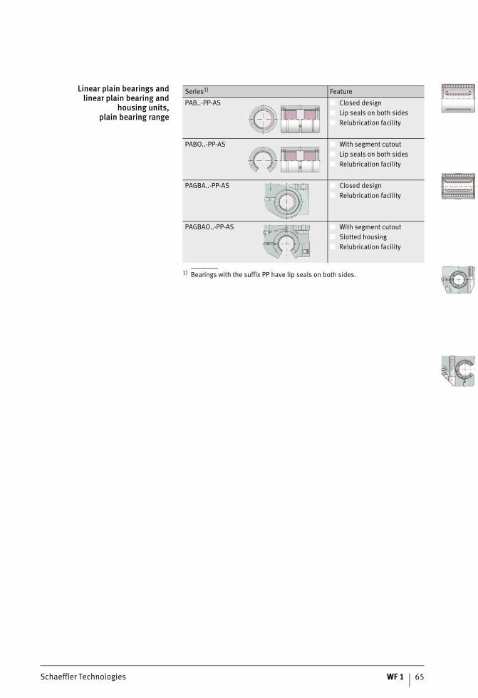
1) Bearings with the suffix PP have lip seals on both sides.
Series1) Feature
PAB..-PP-AS ■ Closed design■ Lip seals on both sides■ Relubrication facility
PABO..-PP-AS ■ With segment cutout■ Lip seals on both sides■ Relubrication facility
PAGBA..-PP-AS ■ Closed design■ Relubrication facility
PAGBAO..-PP-AS ■ With segment cutout■ Slotted housing■ Relubrication facility

66 WF 1 Schaeffler Technologies
Schaeffler Technologies WF 1 67
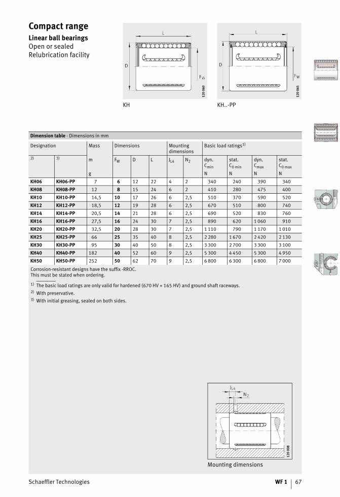
Compact rangeLinear ball bearingsOpen or sealedRelubrication facility
KH KH..-PP
120
060
120
060
120
065
120
065
Corrosion-resistant designs have the suffix -RROC.This must be stated when ordering.
1) The basic load ratings are only valid for hardened (670 HV + 165 HV) and ground shaft raceways.2) With preservative.3) With initial greasing, sealed on both sides.
Dimension table · Dimensions in mm
Designation Mass Dimensions Mountingdimensions
Basic load ratings1)
2) 3) m FW D L JL4 N2 dyn.Cmin
stat.C0 min
dyn.Cmax
stat.C0 max
g N N N N
KH06 KH06-PP 7 6 12 22 4 2 340 240 390 340
KH08 KH08-PP 12 8 15 24 6 2 410 280 475 400
KH10 KH10-PP 14,5 10 17 26 6 2,5 510 370 590 520
KH12 KH12-PP 18,5 12 19 28 6 2,5 670 510 800 740
KH14 KH14-PP 20,5 14 21 28 6 2,5 690 520 830 760
KH16 KH16-PP 27,5 16 24 30 7 2,5 890 620 1 060 910
KH20 KH20-PP 32,5 20 28 30 7 2,5 1 110 790 1 170 1 010
KH25 KH25-PP 66 25 35 40 8 2,5 2 280 1 670 2 420 2 130
KH30 KH30-PP 95 30 40 50 8 2,5 3 300 2 700 3 300 3 100
KH40 KH40-PP 182 40 52 60 9 2,5 5 300 4 450 5 300 4 950
KH50 KH50-PP 252 50 62 70 9 2,5 6 800 6 300 6 800 7 000
Mounting dimensions
120
008
120
008
68 WF 1 Schaeffler Technologies
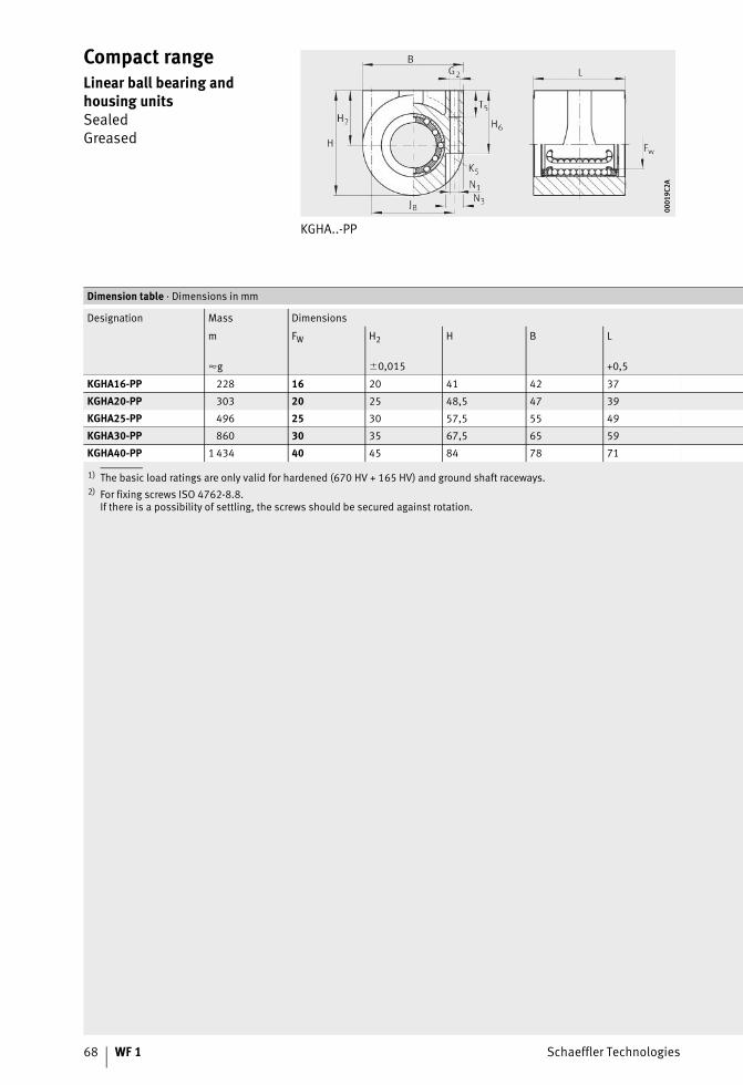
Compact rangeLinear ball bearing and housing unitsSealedGreased
KGHA..-PP
0001
9C2A
0001
9C2A
1) The basic load ratings are only valid for hardened (670 HV + 165 HV) and ground shaft raceways.2) For fixing screws ISO 4762-8.8.
If there is a possibility of settling, the screws should be secured against rotation.
Dimension table · Dimensions in mm
Designation Mass Dimensions
m FW H2 H B L
�g �0,015 +0,5
KGHA16-PP 228 16 20 41 42 37
KGHA20-PP 303 20 25 48,5 47 39
KGHA25-PP 496 25 30 57,5 55 49
KGHA30-PP 860 30 35 67,5 65 59
KGHA40-PP 1 434 40 45 84 78 71
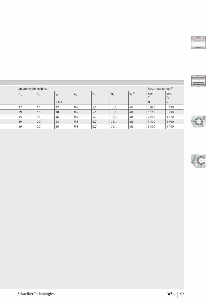
Schaeffler Technologies WF 1 69
Mounting dimensions Basic load ratings1)
H6 T5 JB G2 N1 N3 K52) dyn.
Cstat.C0
�0,1 N N
27 15 32 M6 5,1 8,1 M4 890 620
29 15 38 M6 5,1 8,1 M4 1 110 790
35 15 46 M6 5,1 8,1 M4 2 280 1 670
39 20 54 M8 6,7 11,1 M6 3 300 2 700
49 20 66 M8 6,7 11,1 M6 5 300 4 450
70 WF 1 Schaeffler Technologies
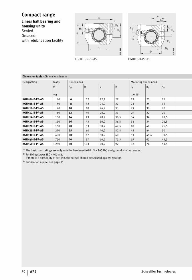
Compact rangeLinear ball bearing and housing unitsSealedGreased,with relubrication facility
KGHK..-B-PP-AS KGHK..-B-PP-AS
120
643
120
643
120
644
120
644
1) The basic load ratings are only valid for hardened (670 HV + 165 HV) and ground shaft raceways.2) For fixing screws ISO 4762-8.8.
If there is a possibility of settling, the screws should be secured against rotation.3) Lubrication nipple, see page 31.
Dimension table · Dimensions in mm
Designation Mass Dimensions Mounting dimensions
m FW B L H JB B1 A5
�g �0,15
KGHK06-B-PP-AS 40 6 32 22,2 27 23 25 16
KGHK08-B-PP-AS 50 8 32 24,2 27 23 25 16
KGHK10-B-PP-AS 70 10 40 26,2 33 29 32 20
KGHK12-B-PP-AS 80 12 40 28,2 33 29 32 20
KGHK14-B-PP-AS 100 14 43 28,2 36,5 34 34 21,5
KGHK16-B-PP-AS 110 16 43 30,2 36,5 34 34 21,5
KGHK20-B-PP-AS 150 20 53 30,2 42,5 40 40 26,5
KGHK25-B-PP-AS 270 25 60 40,2 52,5 48 44 30
KGHK30-B-PP-AS 400 30 67 50,2 60 53 49,6 33,5
KGHK40-B-PP-AS 750 40 87 60,2 73,5 69 63 43,5
KGHK50-B-PP-AS 1 250 50 103 70,2 92 82 74 51,5
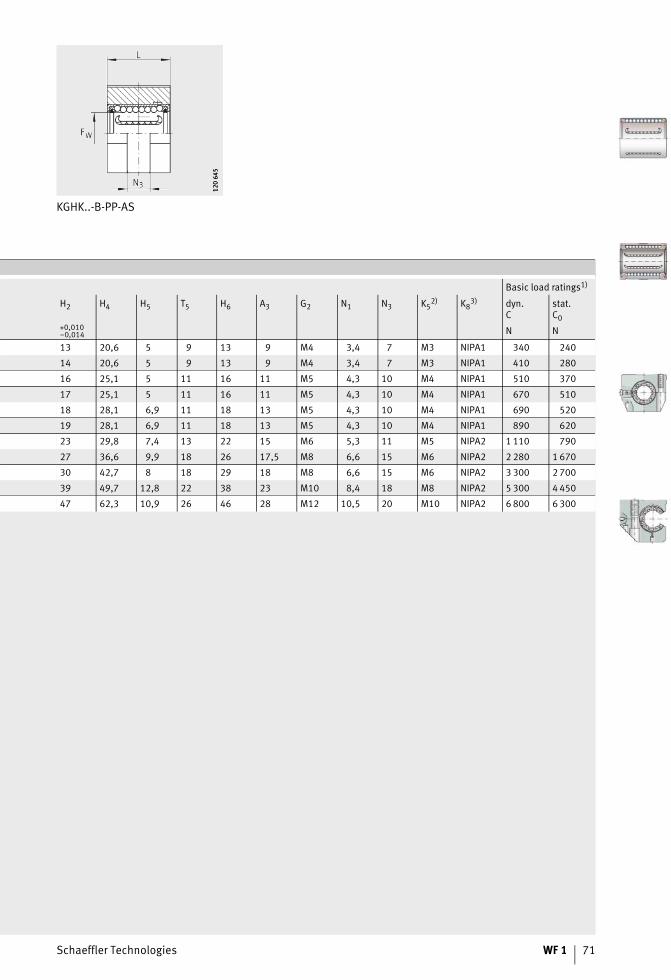
Schaeffler Technologies WF 1 71
KGHK..-B-PP-AS12
0 64
512
0 64
5
Basic load ratings1)
H2 H4 H5 T5 H6 A3 G2 N1 N3 K52) K8
3) dyn.C
stat.C0
+0,010–0,014 N N
13 20,6 5 9 13 9 M4 3,4 7 M3 NIPA1 340 240
14 20,6 5 9 13 9 M4 3,4 7 M3 NIPA1 410 280
16 25,1 5 11 16 11 M5 4,3 10 M4 NIPA1 510 370
17 25,1 5 11 16 11 M5 4,3 10 M4 NIPA1 670 510
18 28,1 6,9 11 18 13 M5 4,3 10 M4 NIPA1 690 520
19 28,1 6,9 11 18 13 M5 4,3 10 M4 NIPA1 890 620
23 29,8 7,4 13 22 15 M6 5,3 11 M5 NIPA2 1 110 790
27 36,6 9,9 18 26 17,5 M8 6,6 15 M6 NIPA2 2 280 1 670
30 42,7 8 18 29 18 M8 6,6 15 M6 NIPA2 3 300 2 700
39 49,7 12,8 22 38 23 M10 8,4 18 M8 NIPA2 5 300 4 450
47 62,3 10,9 26 46 28 M12 10,5 20 M10 NIPA2 6 800 6 300
72 WF 1 Schaeffler Technologies
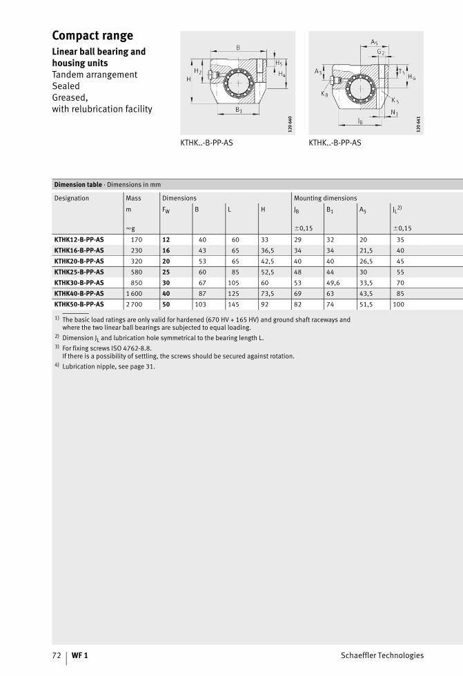
Compact rangeLinear ball bearing and housing unitsTandem arrangementSealedGreased,with relubrication facility
KTHK..-B-PP-AS KTHK..-B-PP-AS
120
640
120
640
120
641
120
641
1) The basic load ratings are only valid for hardened (670 HV + 165 HV) and ground shaft raceways andwhere the two linear ball bearings are subjected to equal loading.
2) Dimension JL and lubrication hole symmetrical to the bearing length L.3) For fixing screws ISO 4762-8.8.
If there is a possibility of settling, the screws should be secured against rotation.4) Lubrication nipple, see page 31.
Dimension table · Dimensions in mm
Designation Mass Dimensions Mounting dimensions
m FW B L H JB B1 A5 JL2)
�g �0,15 �0,15
KTHK12-B-PP-AS 170 12 40 60 33 29 32 20 35
KTHK16-B-PP-AS 230 16 43 65 36,5 34 34 21,5 40
KTHK20-B-PP-AS 320 20 53 65 42,5 40 40 26,5 45
KTHK25-B-PP-AS 580 25 60 85 52,5 48 44 30 55
KTHK30-B-PP-AS 850 30 67 105 60 53 49,6 33,5 70
KTHK40-B-PP-AS 1 600 40 87 125 73,5 69 63 43,5 85
KTHK50-B-PP-AS 2 700 50 103 145 92 82 74 51,5 100
Schaeffler Technologies WF 1 73
KTHK..-B-PP-AS12
0 64
212
0 64
2
Basic load ratings1)
H2 H4 H5 T5 H6 A3 G2 N1 N3 K53) K8
4) dyn.C
stat.C0
+0,010–0,014 N N
17 25,1 5 11 16 11 M5 4,3 10 M4 NIPA1 1 090 1 020
19 28,1 6,9 11 18 13 M5 4,3 10 M4 NIPA1 1 440 1 240
23 29,8 7,4 13 22 15 M6 5,3 11 M5 NIPA2 1 800 1 580
27 36,6 9,9 18 26 17,5 M8 6,6 11 M6 NIPA2 3 700 3 350
30 42,7 8 18 29 18 M8 6,6 15 M6 NIPA2 5 400 5 400
39 49,7 12,8 22 38 23 M10 8,4 18 M8 NIPA2 8 600 6 900
47 62,3 10,9 26 46 28 M12 10,5 20 M10 NIPA2 11 000 12 600
74 WF 1 Schaeffler Technologies
Light rangeLinear ball bearingsSelf-aligningClosed or with segment cutoutOpen or sealedRelubrication facility
KN..-B-PP, KN..-B
120
104
120
104
1) The basic load ratings are only valid for hardened (670 HV + 165 HV) and ground shaft raceways.2) Dimension B2 on diameter FW.3) Hole position symmetrical to bearing length L.4) Basic load rating in main load direction.5)
Dimension table · Dimensions in mm
Designation Mass Dimensions Mounting dimensions
m FW D L B22) L2
�g H13
KN12-B-PP KN12-B – –20 12 22 32
– 22,6
– – KNO12-B-PP KNO12-B 6,5 –
KN16-B-PP KN16-B – – 3016 26 36
– 24,6
– – KNO16-B-PP KNO16-B 20 9 –
KN20-B-PP KN20-B – – 6020 32 45
– 31,2
– – KNO20-B-PP KNO20-B 50 9 –
KN25-B-PP KN25-B – – 13025 40 58
– 43,7
– – KNO25-B-PP KNO25-B 110 11,5 –
KN30-B-PP KN30-B – – 19030 47 68
– 51,7
– – KNO30-B-PP KNO30-B 160 14 –
KN40-B-PP KN40-B – – 35040 62 80
– 60,3
– – KNO40-B-PP KNO40-B 300 19 –
KN50-B-PP KN50-B – – 67050 75 100
– 77,3
– – KNO50-B-PP KNO50-B 570 22,5 –
� Main load direction
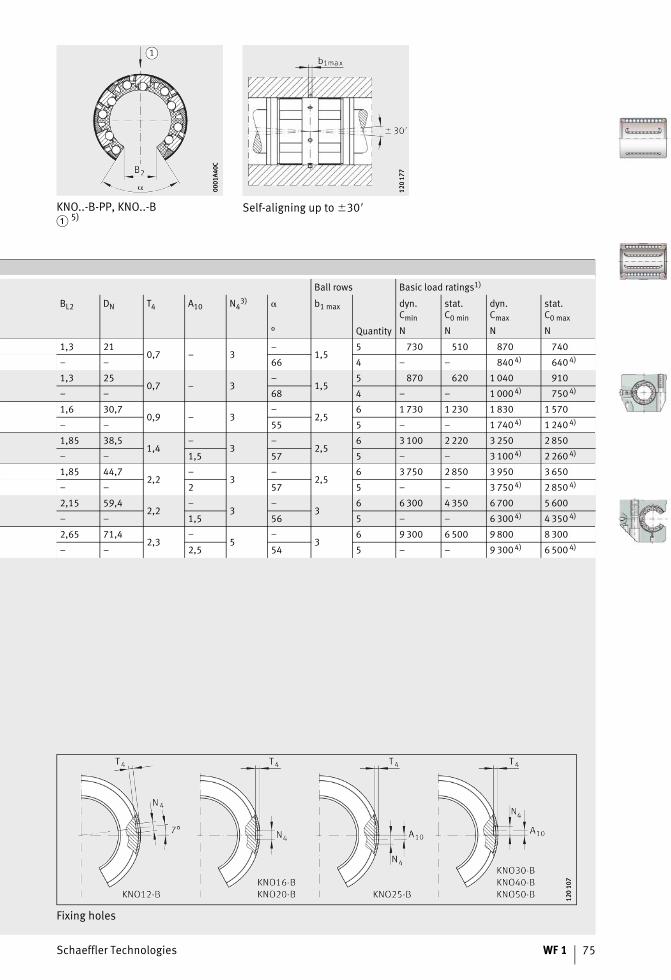
Schaeffler Technologies WF 1 75
KNO..-B-PP, KNO..-B� 5)
Self-aligning up to �30�00
01A4
0C00
01A4
0C
120
177
120
177
Ball rows Basic load ratings1)
BL2 DN T4 A10 N43) � b1 max dyn.
Cmin
stat.C0 min
dyn.Cmax
stat.C0 max
° Quantity N N N N
1,3 210,7 – 3
–1,5
5 730 510 870 740
– – 66 4 – – 840 4) 640 4)
1,3 250,7 – 3
–1,5
5 870 620 1 040 910
– – 68 4 – – 1 000 4) 750 4)
1,6 30,70,9 – 3
–2,5
6 1 730 1 230 1 830 1 570
– – 55 5 – – 1 740 4) 1 240 4)
1,85 38,51,4
–3
–2,5
6 3 100 2 220 3 250 2 850
– – 1,5 57 5 – – 3 100 4) 2 260 4)
1,85 44,72,2
–3
–2,5
6 3 750 2 850 3 950 3 650
– – 2 57 5 – – 3 750 4) 2 850 4)
2,15 59,42,2
–3
–3
6 6 300 4 350 6 700 5 600
– – 1,5 56 5 – – 6 300 4) 4 350 4)
2,65 71,42,3
–5
–3
6 9 300 6 500 9 800 8 300
– – 2,5 54 5 – – 9 300 4) 6 500 4)
Fixing holes
120
107
120
107
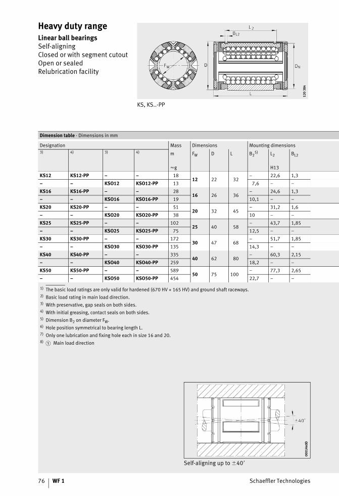
76 WF 1 Schaeffler Technologies
Heavy duty rangeLinear ball bearingsSelf-aligningClosed or with segment cutoutOpen or sealedRelubrication facility
KS, KS..-PP
120
384
120
384
1) The basic load ratings are only valid for hardened (670 HV + 165 HV) and ground shaft raceways.2) Basic load rating in main load direction.3) With preservative, gap seals on both sides.4) With initial greasing, contact seals on both sides.5) Dimension B2 on diameter FW.6) Hole position symmetrical to bearing length L.7) Only one lubrication and fixing hole each in size 16 and 20.8)
Dimension table · Dimensions in mm
Designation Mass Dimensions Mounting dimensions3) 4) 3) 4) m FW D L B2
5) L2 BL2
�g H13
KS12 KS12-PP – – 1812 22 32
– 22,6 1,3
– – KSO12 KSO12-PP 13 7,6 – –
KS16 KS16-PP – – 2816 26 36
– 24,6 1,3
– – KSO16 KSO16-PP 19 10,1 – –
KS20 KS20-PP – – 5120 32 45
– 31,2 1,6
– – KSO20 KSO20-PP 38 10 – –
KS25 KS25-PP – – 10225 40 58
– 43,7 1,85
– – KSO25 KSO25-PP 75 12,5 – –
KS30 KS30-PP – – 17230 47 68
– 51,7 1,85
– – KSO30 KSO30-PP 135 14,3 – –
KS40 KS40-PP – – 33540 62 80
– 60,3 2,15
– – KSO40 KSO40-PP 259 18,2 – –
KS50 KS50-PP – – 58950 75 100
– 77,3 2,65
– – KSO50 KSO50-PP 454 22,7 – –
� Main load direction
Self-aligning up to �40�
0001
A40D
0001
A40D
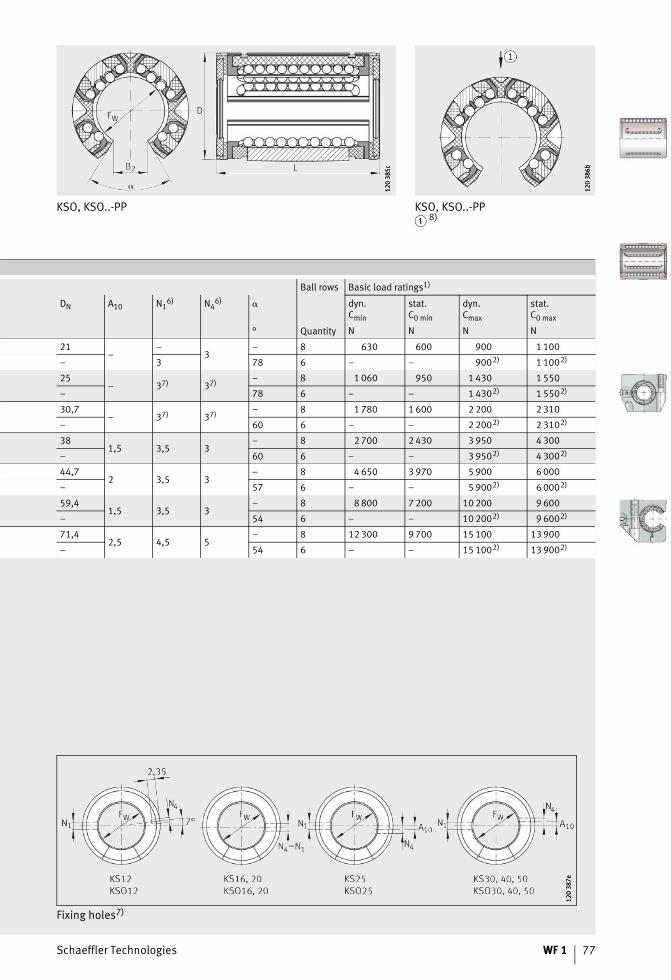
Schaeffler Technologies WF 1 77
KSO, KSO..-PP
120
385c
120
385c
KSO, KSO..-PP� 8)
120
386b
120
386b
Ball rows Basic load ratings1)
DN A10 N16) N4
6) � dyn.Cmin
stat.C0 min
dyn.Cmax
stat.C0 max
° Quantity N N N N
21–
–3
– 8 630 600 900 1 100
– 3 78 6 – – 9002) 1 1002)
25– 37) 37) – 8 1 060 950 1 430 1 550
– 78 6 – – 1 4302) 1 5502)
30,7– 37) 37) – 8 1 780 1 600 2 200 2 310
– 60 6 – – 2 2002) 2 3102)
381,5 3,5 3
– 8 2 700 2 430 3 950 4 300
– 60 6 – – 3 9502) 4 3002)
44,72 3,5 3
– 8 4 650 3 970 5 900 6 000
– 57 6 – – 5 9002) 6 0002)
59,41,5 3,5 3
– 8 8 800 7 200 10 200 9 600
– 54 6 – – 10 2002) 9 6002)
71,42,5 4,5 5
– 8 12 300 9 700 15 100 13 900
– 54 6 – – 15 1002) 13 9002)
Fixing holes7)
120
387e
120
387e
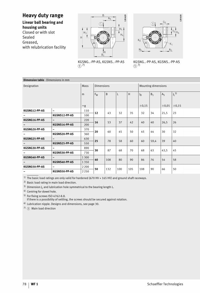
78 WF 1 Schaeffler Technologies
Heavy duty rangeLinear ball bearing and housing unitsClosed or with slotSealedGreased,with relubrication facility
KGSNG..-PP-AS, KGSNS..-PP-AS� 7)
KGSNG..-PP-AS, KGSNS..-PP-AS� 7)
120
629
120
629
120
630
120
630
1) The basic load ratings are only valid for hardened (670 HV + 165 HV) and ground shaft raceways.2) Basic load rating in main load direction.3) Dimension JL and lubrication hole symmetrical to the bearing length L.4) Centring for dowel hole.5) For fixing screws ISO 4762-8.8.
If there is a possibility of settling, the screws should be secured against rotation.6) Lubrication nipple. Designs and dimensions, see page 30.7)
Dimension table · Dimensions in mm
Designation Mass Dimensions Mounting dimensions
m FW B L H JB B1 A5 JL3)
�g �0,15 �0,01 �0,15
KGSNG12-PP-AS – 11012 43 32 35 32 34 21,5 23
– KGSNS12-PP-AS 100
KGSNG16-PP-AS – 22016 53 37 42 40 40 26,5 26
– KGSNS16-PP-AS 200
KGSNG20-PP-AS – 37020 60 45 50 45 44 30 32
– KGSNS20-PP-AS 360
KGSNG25-PP-AS – 63025 78 58 60 60 59,4 39 40
– KGSNS25-PP-AS 550
KGSNG30-PP-AS – 89030 87 68 70 68 63 43,5 45
– KGSNS30-PP-AS 730
KGSNG40-PP-AS – 1 30040 108 80 90 86 76 54 58
– KGSNS40-PP-AS 1 350
KGSNG50-PP-AS – 2 20050 132 100 105 108 90 66 50
– KGSNS50-PP-AS 2 250
� Main load direction
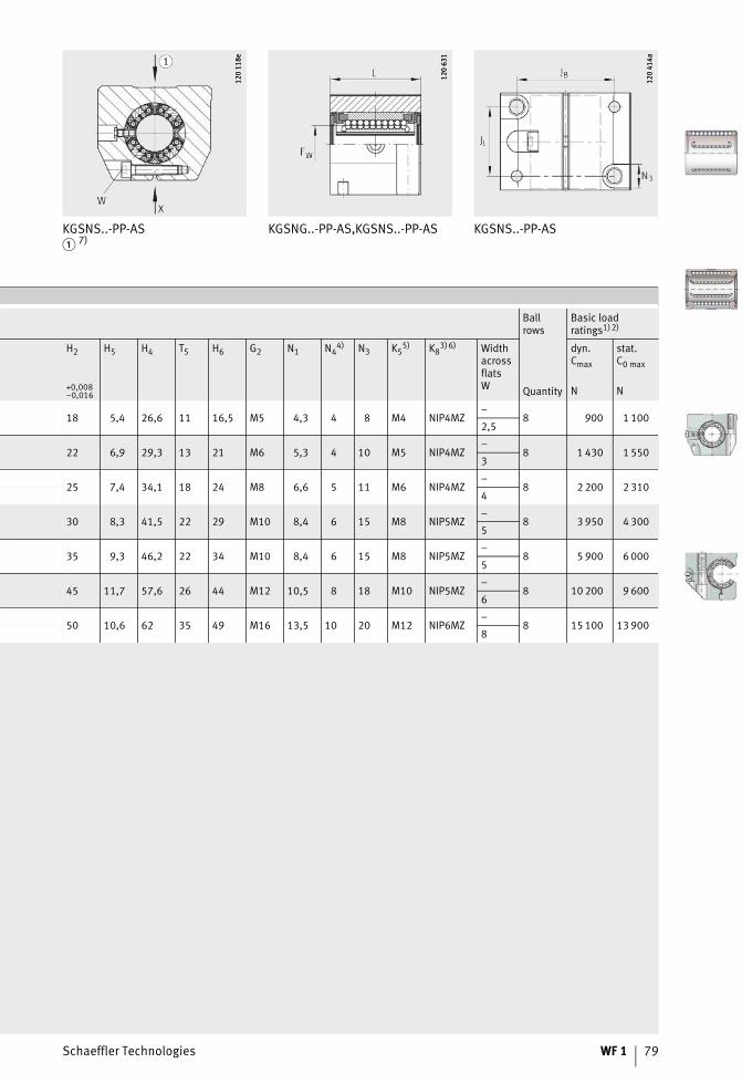
Schaeffler Technologies WF 1 79
KGSNS..-PP-AS� 7)
KGSNG..-PP-AS,KGSNS..-PP-AS KGSNS..-PP-AS12
0 11
8e12
0 11
8e
120
631
120
631
120
414a
120
414a
Ballrows
Basic loadratings1)2)
H2 H5 H4 T5 H6 G2 N1 N44) N3 K5
5) K83) 6) Width
acrossflatsW
dyn.Cmax
stat.C0 max
+0,008–0,016 Quantity N N
18 5,4 26,6 11 16,5 M5 4,3 4 8 M4 NIP4MZ–
8 900 1 1002,5
22 6,9 29,3 13 21 M6 5,3 4 10 M5 NIP4MZ–
8 1 430 1 5503
25 7,4 34,1 18 24 M8 6,6 5 11 M6 NIP4MZ–
8 2 200 2 3104
30 8,3 41,5 22 29 M10 8,4 6 15 M8 NIP5MZ–
8 3 950 4 3005
35 9,3 46,2 22 34 M10 8,4 6 15 M8 NIP5MZ–
8 5 900 6 0005
45 11,7 57,6 26 44 M12 10,5 8 18 M10 NIP5MZ–
8 10 200 9 6006
50 10,6 62 35 49 M16 13,5 10 20 M12 NIP6MZ–
8 15 100 13 9008
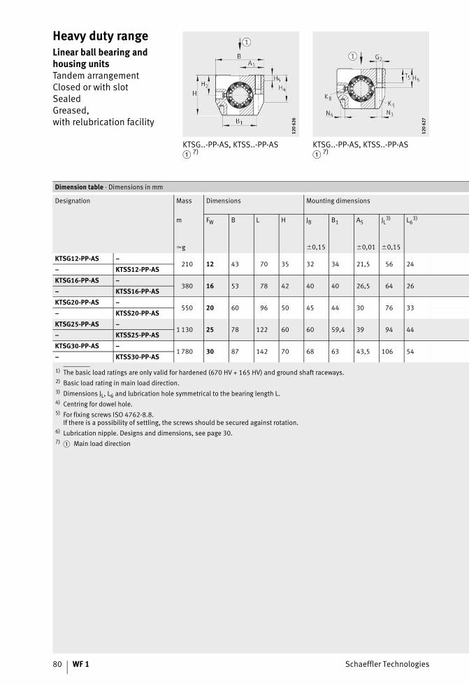
80 WF 1 Schaeffler Technologies
Heavy duty rangeLinear ball bearing and housing unitsTandem arrangementClosed or with slotSealedGreased,with relubrication facility
KTSG..-PP-AS, KTSS..-PP-AS� 7)
KTSG..-PP-AS, KTSS..-PP-AS� 7)
120
626
120
626
120
627
120
627
1) The basic load ratings are only valid for hardened (670 HV + 165 HV) and ground shaft raceways.2) Basic load rating in main load direction.3) Dimensions JL, L6 and lubrication hole symmetrical to the bearing length L.4) Centring for dowel hole.5) For fixing screws ISO 4762-8.8.
If there is a possibility of settling, the screws should be secured against rotation.6) Lubrication nipple. Designs and dimensions, see page 30.7)
Dimension table · Dimensions in mm
Designation Mass Dimensions Mounting dimensions
m FW B L H JB B1 A5 JL3) L63)
�g �0,15 �0,01 �0,15
KTSG12-PP-AS –210 12 43 70 35 32 34 21,5 56 24
– KTSS12-PP-ASKTSG16-PP-AS –
380 16 53 78 42 40 40 26,5 64 26– KTSS16-PP-ASKTSG20-PP-AS –
550 20 60 96 50 45 44 30 76 33– KTSS20-PP-ASKTSG25-PP-AS –
1 130 25 78 122 60 60 59,4 39 94 44– KTSS25-PP-ASKTSG30-PP-AS –
1 780 30 87 142 70 68 63 43,5 106 54– KTSS30-PP-AS
� Main load direction
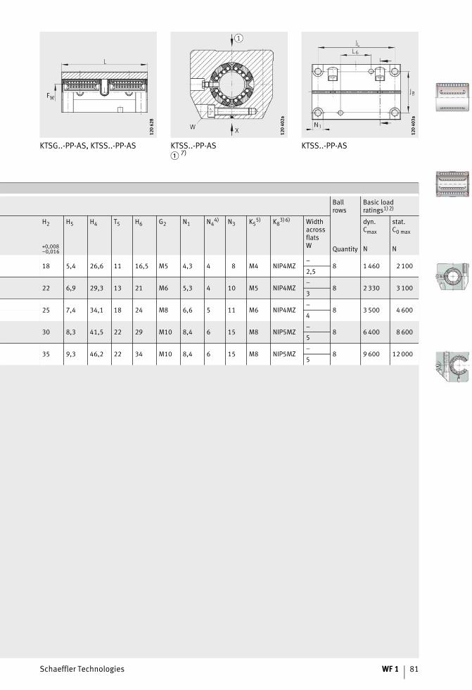
Schaeffler Technologies WF 1 81
KTSG..-PP-AS, KTSS..-PP-AS KTSS..-PP-AS� 7)
KTSS..-PP-AS12
0 62
812
0 62
8
120
402a
120
402a
120
403a
120
403a
Ballrows
Basic loadratings1)2)
H2 H5 H4 T5 H6 G2 N1 N44) N3 K5
5) K83) 6) Width
acrossflatsW
dyn.Cmax
stat.C0 max
+0,008–0,016 Quantity N N
18 5,4 26,6 11 16,5 M5 4,3 4 8 M4 NIP4MZ–
8 1 460 2 1002,5
22 6,9 29,3 13 21 M6 5,3 4 10 M5 NIP4MZ–
8 2 330 3 1003
25 7,4 34,1 18 24 M8 6,6 5 11 M6 NIP4MZ–
8 3 500 4 6004
30 8,3 41,5 22 29 M10 8,4 6 15 M8 NIP5MZ–
8 6 400 8 6005
35 9,3 46,2 22 34 M10 8,4 6 15 M8 NIP5MZ–
8 9 600 12 0005
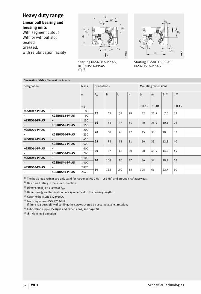
82 WF 1 Schaeffler Technologies
Heavy duty rangeLinear ball bearing and housing unitsWith segment cutoutWith or without slotSealedGreased,with relubrication facility
Starting KGSNO16-PP-AS, KGSNOS16-PP-AS� 8)
Starting KGSNO16-PP-AS, KGSNOS16-PP-AS
120
623
120
623
120
624
120
624
1) The basic load ratings are only valid for hardened (670 HV + 165 HV) and ground shaft raceways.2) Basic load rating in main load direction.3) Dimension B2 on diameter FW.4) Dimension JL and lubrication hole symmetrical to the bearing length L.5) Centring hole DIN 332 type A.6) For fixing screws ISO 4762-8.8.
If there is a possibility of settling, the screws should be secured against rotation.7) Lubrication nipple. Designs and dimensions, see page 30.8)
Dimension table · Dimensions in mm
Designation Mass Dimensions Mounting dimensions
m FW B L H JB A5 B23) JL4)
�g �0,15 �0,01 �0,15
KGSNO12-PP-AS – 8012 43 32 28 32 21,5 7,6 23
– KGSNOS12-PP-AS 90
KGSNO16-PP-AS – 15016 53 37 35 40 26,5 10,1 26
– KGSNOS16-PP-AS 150
KGSNO20-PP-AS – 20020 60 45 42 45 30 10 32
– KGSNOS20-PP-AS 250
KGSNO25-PP-AS – 41025 78 58 51 60 39 12,5 40
– KGSNOS25-PP-AS 520
KGSNO30-PP-AS – 60030 87 68 60 68 43,5 14,3 45
– KGSNOS30-PP-AS 760
KGSNO40-PP-AS – 1 10040 108 80 77 86 54 18,2 58
– KGSNOS40-PP-AS 1 400
KGSNO50-PP-AS – 2 87050 132 100 88 108 66 22,7 50
– KGSNOS50-PP-AS 2 670
� Main load direction
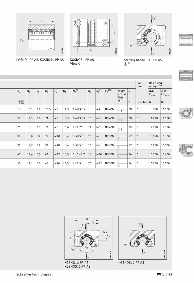
Schaeffler Technologies WF 1 83
KGSNO..-PP-AS, KGSNOS..-PP-AS KGSNOS..-PP-ASView X
Starting KGSNOS16-PP-AS� 8)
120
120f
120
120f
120
256f
120
256f
120
120e
120
120e
Ballrows
Basic loadratings1)2)
H2 H5 T5 H6 G2 N1 N45) N3 K5
6) K84) 7) Width
acrossflatsW
� dyn.Cmax
stat.C0 max
+0,008–0,016 ° Quantity N N
18 6,1 11 16,5 M5 4,3 1,6�3,35 8 M4 NIP4MZ–
78 6 900 1 1002,5
22 7,5 13 21 M6 5,3 1,6�3,35 10 M5 NIP4MZ–
68 6 1 430 1 5502,5
25 8 18 24 M8 6,6 2�4,25 11 M6 NIP4MZ–
55 6 2 200 2 3102,5
30 8,8 22 29 M10 8,4 2,5�5,3 15 M8 NIP5MZ–
57 6 3 950 4 3003
35 9,7 22 34 M10 8,4 2,5�5,3 15 M8 NIP5MZ–
57 6 5 900 6 0003
45 12,4 26 44 M12 10,5 3,15�6,7 18 M10 NIP5MZ–
56 6 10 200 9 6004
50 11,1 35 49 M16 13,5 4�8,5 20 M12 NIP5MZ–
54 6 15 100 13 9005
KGSNO12-PP-AS,KGSNOS12-PP-AS
KGSNOS12-PP-AS
0001
9C30
0001
9C30
0001
9C31
0001
9C31
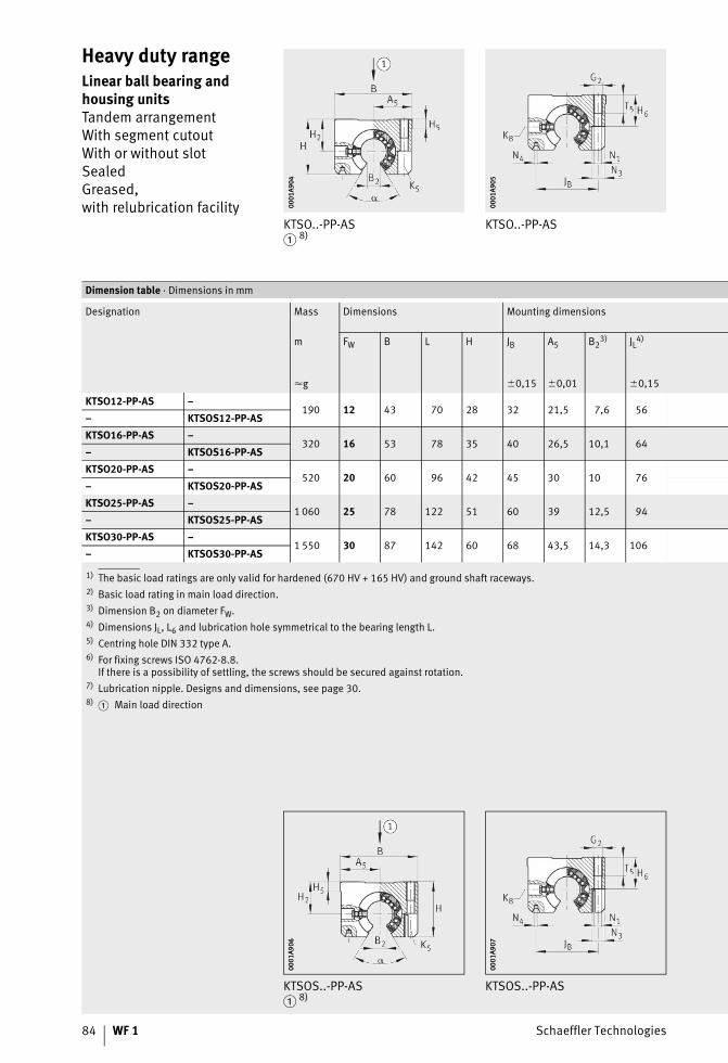
84 WF 1 Schaeffler Technologies
Heavy duty rangeLinear ball bearing and housing unitsTandem arrangementWith segment cutoutWith or without slotSealedGreased,with relubrication facility
KTSO..-PP-AS� 8)
KTSO..-PP-AS
0001
A904
0001
A904
0001
A905
0001
A905
1) The basic load ratings are only valid for hardened (670 HV + 165 HV) and ground shaft raceways.2) Basic load rating in main load direction.3) Dimension B2 on diameter FW.4) Dimensions JL, L6 and lubrication hole symmetrical to the bearing length L.5) Centring hole DIN 332 type A.6) For fixing screws ISO 4762-8.8.
If there is a possibility of settling, the screws should be secured against rotation.7) Lubrication nipple. Designs and dimensions, see page 30.8)
Dimension table · Dimensions in mm
Designation Mass Dimensions Mounting dimensions
m FW B L H JB A5 B23) JL4)
�g �0,15 �0,01 �0,15
KTSO12-PP-AS –190 12 43 70 28 32 21,5 7,6 56
– KTSOS12-PP-ASKTSO16-PP-AS –
320 16 53 78 35 40 26,5 10,1 64– KTSOS16-PP-ASKTSO20-PP-AS –
520 20 60 96 42 45 30 10 76– KTSOS20-PP-ASKTSO25-PP-AS –
1 060 25 78 122 51 60 39 12,5 94– KTSOS25-PP-ASKTSO30-PP-AS –
1 550 30 87 142 60 68 43,5 14,3 106– KTSOS30-PP-AS
� Main load direction
KTSOS..-PP-AS� 8)
KTSOS..-PP-AS
0001
A906
0001
A906
0001
A907
0001
A907
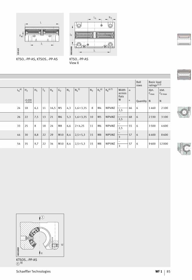
Schaeffler Technologies WF 1 85
KTSO..-PP-AS, KTSOS..-PP-AS KTSO..-PP-ASView X
120
622
120
622
0001
A908
0001
A908
Ballrows
Basic loadratings1)2)
L64) H2 H5 T5 H6 G2 N1 N4
5) N3 K56) K8
4)7) WidthacrossflatsW
� dyn.Cmax
stat.C0 max
+0,008–0,016 ° Quantity N N
24 18 6,1 11 16,5 M5 4,3 1,6�3,35 8 M4 NIP4MZ–
66 6 1 460 2 1002,5
26 22 7,5 13 21 M6 5,3 1,6�3,35 10 M5 NIP4MZ–
68 6 2 330 3 1002,5
33 25 8 18 24 M8 6,6 2�4,25 11 M6 NIP4MZ–
55 6 3 500 4 6002,5
44 30 8,8 22 29 M10 8,4 2,5�5,3 15 M8 NIP5MZ–
57 6 6 400 8 6003
54 35 9,7 22 34 M10 8,4 2,5�5,3 15 M8 NIP5MZ–
57 6 9 600 12 0003
KTSOS..-PP-AS� 8)
0001
A909
0001
A909
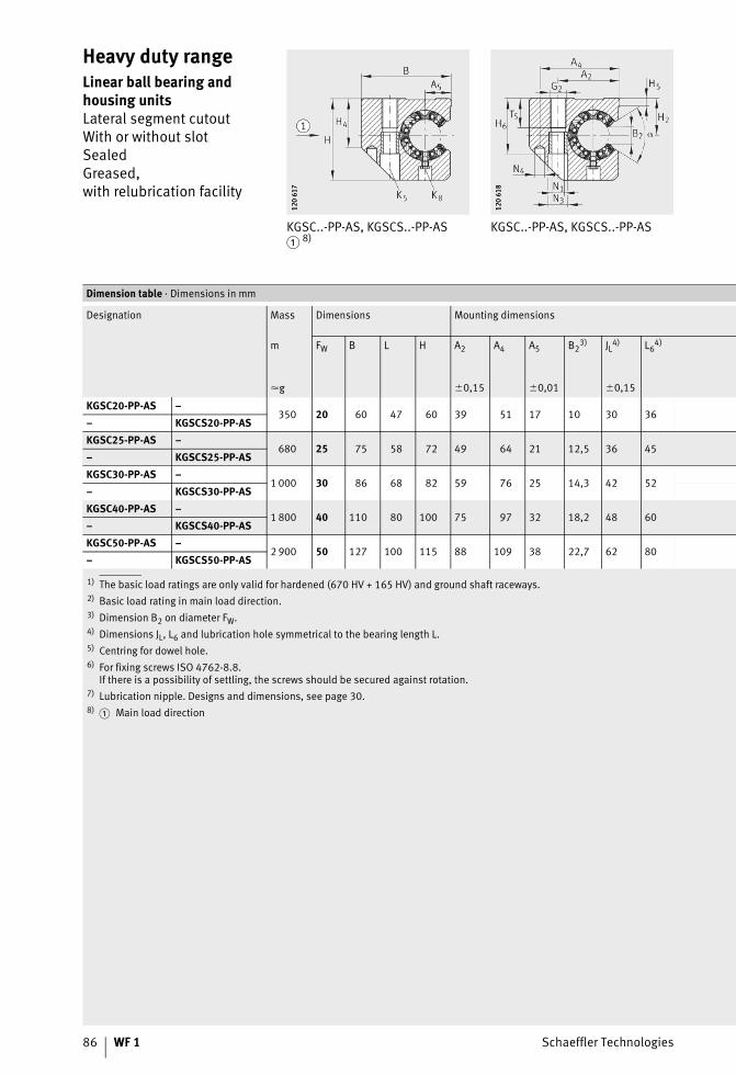
86 WF 1 Schaeffler Technologies
Heavy duty rangeLinear ball bearing and housing unitsLateral segment cutoutWith or without slotSealedGreased,with relubrication facility
KGSC..-PP-AS, KGSCS..-PP-AS� 8)
KGSC..-PP-AS, KGSCS..-PP-AS
120
617
120
617
120
618
120
618
1) The basic load ratings are only valid for hardened (670 HV + 165 HV) and ground shaft raceways.2) Basic load rating in main load direction.3) Dimension B2 on diameter FW.4) Dimensions JL, L6 and lubrication hole symmetrical to the bearing length L.5) Centring for dowel hole.6) For fixing screws ISO 4762-8.8.
If there is a possibility of settling, the screws should be secured against rotation.7) Lubrication nipple. Designs and dimensions, see page 30.8)
Dimension table · Dimensions in mm
Designation Mass Dimensions Mounting dimensions
m FW B L H A2 A4 A5 B23) JL4) L6
4)
�g �0,15 �0,01 �0,15
KGSC20-PP-AS –350 20 60 47 60 39 51 17 10 30 36
– KGSCS20-PP-ASKGSC25-PP-AS –
680 25 75 58 72 49 64 21 12,5 36 45– KGSCS25-PP-ASKGSC30-PP-AS –
1 000 30 86 68 82 59 76 25 14,3 42 52– KGSCS30-PP-ASKGSC40-PP-AS –
1 800 40 110 80 100 75 97 32 18,2 48 60– KGSCS40-PP-ASKGSC50-PP-AS –
2 900 50 127 100 115 88 109 38 22,7 62 80– KGSCS50-PP-AS
� Main load direction
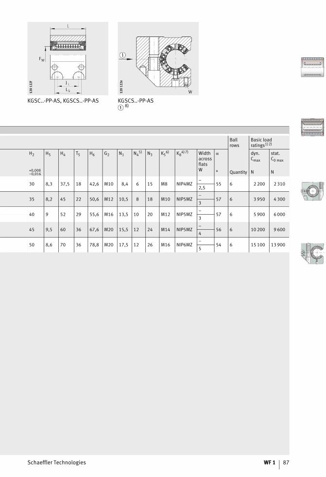
Schaeffler Technologies WF 1 87
KGSC..-PP-AS, KGSCS..-PP-AS KGSCS..-PP-AS� 8)
120
122f
120
122f
120
122e
120
122e
Ballrows
Basic loadratings1)2)
H2 H5 H4 T5 H6 G2 N1 N45) N3 K5
6) K84) 7) Width
acrossflatsW
� dyn.Cmax
stat.C0 max
+0,008–0,016 ° Quantity N N
30 8,3 37,5 18 42,6 M10 8,4 6 15 M8 NIP4MZ–
55 6 2 200 2 3102,5
35 8,2 45 22 50,6 M12 10,5 8 18 M10 NIP5MZ–
57 6 3 950 4 3003
40 9 52 29 55,6 M16 13,5 10 20 M12 NIP5MZ–
57 6 5 900 6 0003
45 9,5 60 36 67,6 M20 15,5 12 24 M14 NIP5MZ–
56 6 10 200 9 6004
50 8,6 70 36 78,8 M20 17,5 12 26 M16 NIP6MZ–
54 6 15 100 13 9005
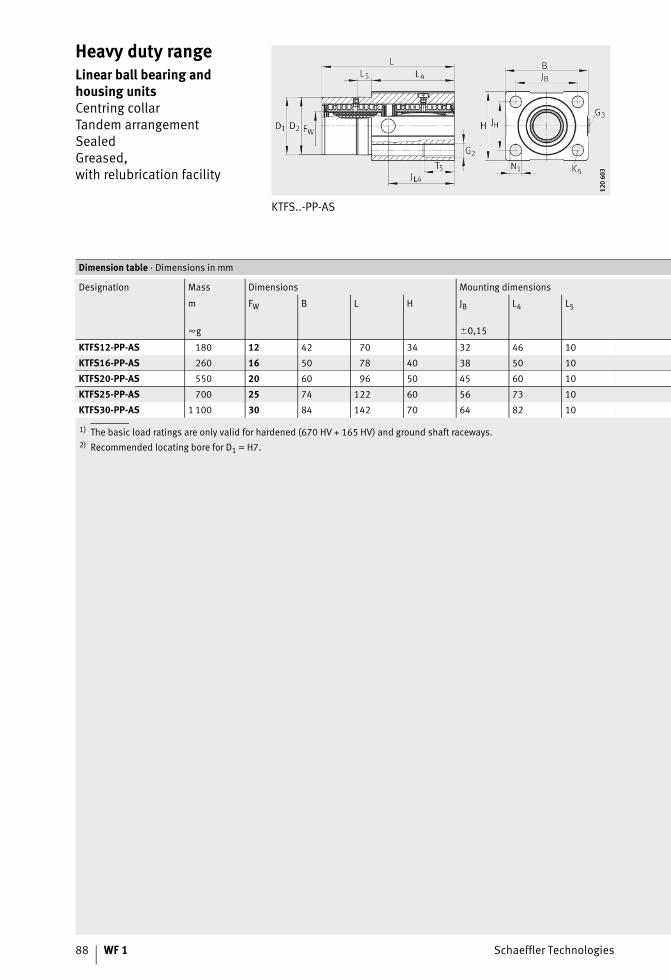
88 WF 1 Schaeffler Technologies
Heavy duty rangeLinear ball bearing and housing unitsCentring collarTandem arrangementSealedGreased,with relubrication facility
KTFS..-PP-AS
120
603
120
603
1) The basic load ratings are only valid for hardened (670 HV + 165 HV) and ground shaft raceways.2) Recommended locating bore for D1 = H7.
Dimension table · Dimensions in mm
Designation Mass Dimensions Mounting dimensions
m FW B L H JB L4 L5
�g �0,15
KTFS12-PP-AS 180 12 42 70 34 32 46 10
KTFS16-PP-AS 260 16 50 78 40 38 50 10
KTFS20-PP-AS 550 20 60 96 50 45 60 10
KTFS25-PP-AS 700 25 74 122 60 56 73 10
KTFS30-PP-AS 1 100 30 84 142 70 64 82 10
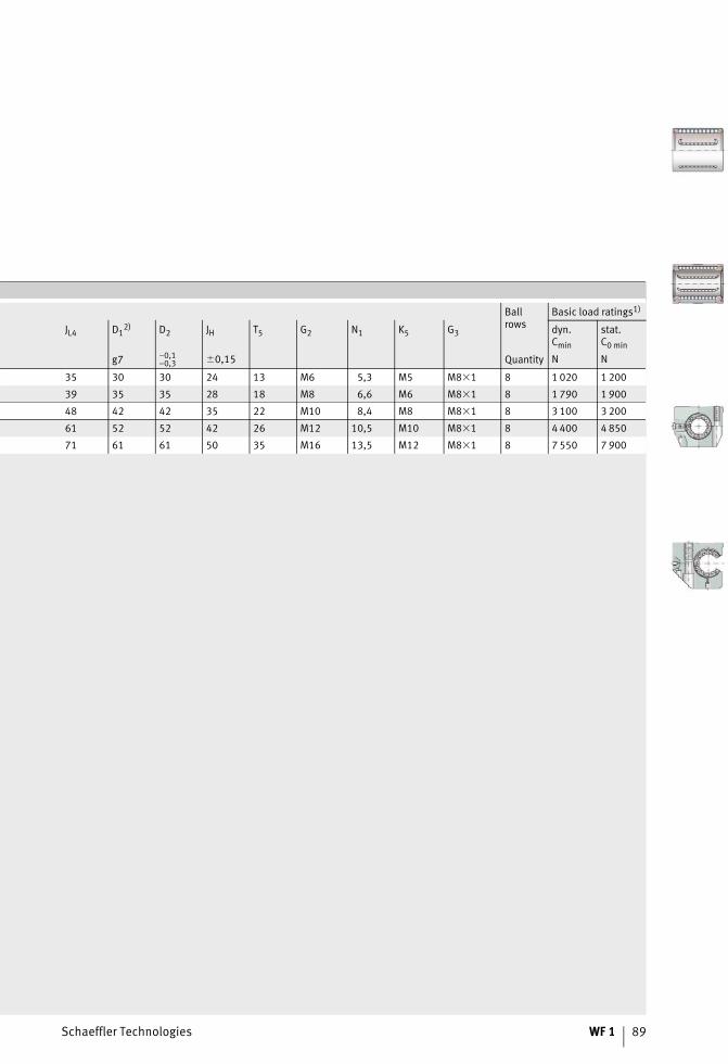
Schaeffler Technologies WF 1 89
Ballrows
Basic load ratings1)
JL4 D12) D2 JH T5 G2 N1 K5 G3 dyn.
Cmin
stat.C0 min
g7 –0,1–0,3 �0,15 Quantity N N
35 30 30 24 13 M6 5,3 M5 M8�1 8 1 020 1 200
39 35 35 28 18 M8 6,6 M6 M8�1 8 1 790 1 900
48 42 42 35 22 M10 8,4 M8 M8�1 8 3 100 3 200
61 52 52 42 26 M12 10,5 M10 M8�1 8 4 400 4 850
71 61 61 50 35 M16 13,5 M12 M8�1 8 7 550 7 900
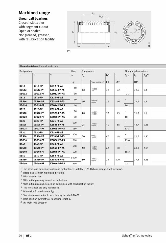
90 WF 1 Schaeffler Technologies
Machined rangeLinear ball bearingsClosed, slotted orwith segment cutoutOpen or sealedNot greased, greased,with relubrication facility
KB
120
021
120
021
1) The basic load ratings are only valid for hardened (670 HV + 165 HV) and ground shaft raceways.2) Basic load rating in main load direction.3) With preservative.4) With initial greasing, sealed on both sides.5) With initial greasing, sealed on both sides, with relubrication facility.6) The tolerances are only valid for KB.7) Dimension B2 on diameter FW.8) Slot dimensions suitable for retaining rings to DIN 471.9) Hole position symmetrical to bearing length L.
10)
Dimension table · Dimensions in mm
Designation Mass Dimensions Mounting dimensions3) 4) 5) m Fw D6) L B2
7) L2 BL28)
�g Tolerances6) h5 h12 H13
KB12 KB12-PP KB12-PP-AS40
12 +0,0080 22 32
–22,6 1,3KBS12 KBS12-PP KBS12-PP-AS
KBO12 KBO12-PP KBO12-PP-AS 30 7,7
KB16 KB16-PP KB16-PP-AS50
16 +0,009–0,001 26 36
–24,6 1,3KBS16 KBS16-PP KBS16-PP-AS
KBO16 KBO16-PP KBO16-PP-AS 40 10,1
KB20 KB20-PP KB20-PP-AS90
20 +0,009–0,001 32 45
–31,2 1,6KBS20 KBS20-PP KBS20-PP-AS
KBO20 KBO20-PP KBO20-PP-AS 70 10
KB25 KB25-PP KB25-PP-AS190
25 +0,011–0,001 40 58
–43,7 1,85KBS25 KBS25-PP KBS25-PP-AS
KBO25 KBO25-PP KBO25-PP-AS 150 12,5
KB30 KB30-PP KB30-PP-AS300
30 +0,011–0,001 47 68
–51,7 1,85KBS30 KBS30-PP KBS30-PP-AS
KBO30 KBO30-PP KBO30-PP-AS 240 13,6
KB40 KB40-PP KB40-PP-AS600
40 +0,013–0,002 62 80
–60,3 2,15KBS40 KBS40-PP KBS40-PP-AS
KBO40 KBO40-PP KBO40-PP-AS 520 18,2
KB50 KB50-PP KB50-PP-AS1 000
50 +0,013–0,002 75 100
–77,3 2,65KBS50 KBS50-PP KBS50-PP-AS
KBO50 KBO50-PP KBO50-PP-AS 850 22,7
� Main load direction
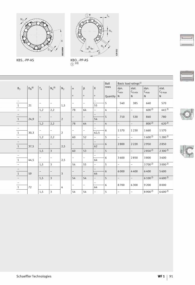
Schaeffler Technologies WF 1 91
KBS..-PP-AS KBO..-PP-AS� 10)
0001
A90A
0001
A90A
120
032
120
032
Ballrows
Basic load ratings1)
B3 DN8) T4 N4
9) N2 � X dyn.Cmin
stat.C0 min
dyn.Cmax
stat.C0 max
° ° ° Quantity N N N N
–
21– –
1,5– –
–5 540 385 640 570
1 55
– 1,2 2,2 78 64 – 4 – – 600 2) 445 2)
–
24,9– –
2– –
–5 710 530 840 780
1 54
– 1,2 2,2 78 64 – 4 – – 800 2) 620 2)
–
30,3– –
2– –
–6 1 570 1 230 1 660 1 570
1 62,5
– 1,2 2,2 60 52 – 5 – – 1 600 2) 1 280 2)
–
37,5– –
2,5– –
–6 2 800 2 220 2 950 2 850
1 62
– 1,5 3 60 53 – 5 – – 2 850 2) 2 300 2)
–
44,5– –
2,5– –
–6 3 600 2 850 3 800 3 600
1 64
– 1,5 3 54 55 – 5 – – 3 700 2) 3 000 2)
–
59– –
3– –
–6 6 000 4 400 6 400 5 600
1 64
– 1,5 3 54 54 – 5 – – 6 100 2) 4 600 2)
–
72– –
4– –
–6 8 700 6 300 9 200 8 000
1 64
– 1,5 3 54 54 – 5 – – 8 900 2) 6 600 2)
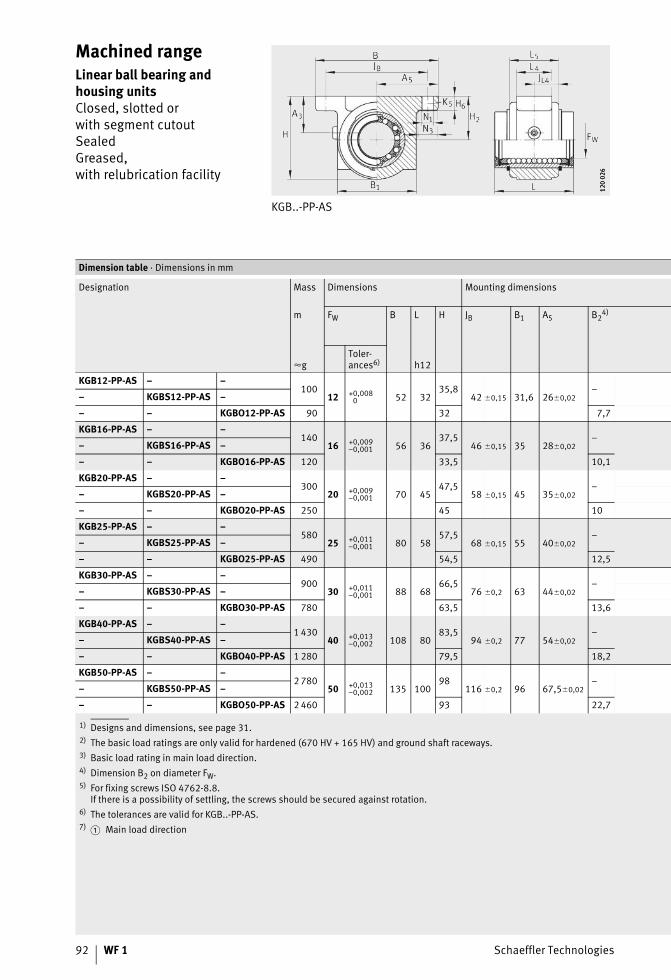
92 WF 1 Schaeffler Technologies
Machined rangeLinear ball bearing and housing unitsClosed, slotted orwith segment cutoutSealedGreased,with relubrication facility
KGB..-PP-AS
120
026
120
026
1) Designs and dimensions, see page 31.2) The basic load ratings are only valid for hardened (670 HV + 165 HV) and ground shaft raceways.3) Basic load rating in main load direction.4) Dimension B2 on diameter FW.5) For fixing screws ISO 4762-8.8.
If there is a possibility of settling, the screws should be secured against rotation.6) The tolerances are valid for KGB..-PP-AS.7)
Dimension table · Dimensions in mm
Designation Mass Dimensions Mounting dimensions
m FW B L H JB B1 A5 B24)
�gToler-ances6) h12
KGB12-PP-AS – –100
12 +0,0080 52 32
35,842 �0,15 31,6 26�0,02
–– KGBS12-PP-AS –
– – KGBO12-PP-AS 90 32 7,7
KGB16-PP-AS – –140
16 +0,009–0,001 56 36
37,546 �0,15 35 28�0,02
–– KGBS16-PP-AS –
– – KGBO16-PP-AS 120 33,5 10,1
KGB20-PP-AS – –300
20 +0,009–0,001 70 45
47,558 �0,15 45 35�0,02
–– KGBS20-PP-AS –
– – KGBO20-PP-AS 250 45 10
KGB25-PP-AS – –580
25 +0,011–0,001 80 58
57,568 �0,15 55 40�0,02
–– KGBS25-PP-AS –
– – KGBO25-PP-AS 490 54,5 12,5
KGB30-PP-AS – –900
30 +0,011–0,001 88 68
66,576 �0,2 63 44�0,02
–– KGBS30-PP-AS –
– – KGBO30-PP-AS 780 63,5 13,6
KGB40-PP-AS – –1 430
40 +0,013–0,002 108 80
83,594 �0,2 77 54�0,02
–– KGBS40-PP-AS –
– – KGBO40-PP-AS 1 280 79,5 18,2
KGB50-PP-AS – –2 780
50 +0,013–0,002 135 100
98116 �0,2 96 67,5�0,02
–– KGBS50-PP-AS –
– – KGBO50-PP-AS 2 460 93 22,7
� Main load direction
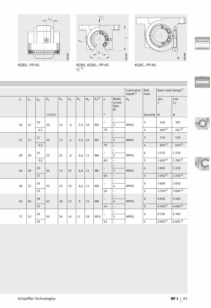
Schaeffler Technologies WF 1 93
KGBO..-PP-AS KGBO, KGBO..-PP-AS� 7)
KGBS..-PP-AS12
0 03
512
0 03
5
120
247
120
247
120
049
120
049
Lubricationnipple1)
Ballrows
Basic load ratings2)
L5 L4 JL4 H2 A3 H6 N1 N3 K55) � Width
acrossflatsW
K8 dyn.C
stat.C0
�0,015 ° Quantity N N
20 1210
20 15 6 5,5 10 M5–
–
NIPA15 540 385
2
6,5 78 – 4 600 3) 445 3)
22 1511
20 15 6 5,5 10 M5–
–
NIPA15 710 530
2
6,5 78 – 4 800 3) 620 3)
28 2014
25 21 8 6,6 11 M6–
–
NIPA16 1 570 1 230
3
9,5 60 – 5 1 600 3) 1 280 3)
40 2820
30 23 10 6,6 11 M6–
–
NIPA16 2 800 2 220
3
15 60 – 5 2 850 3) 2 330 3)
48 3224
35 25 10 6,6 11 M6–
–
NIPA26 3 600 2 850
4
19 54 – 5 3 700 3) 3 000 3)
56 4028
45 30 12 9 15 M8–
–
NIPA26 6 000 4 400
4
23 54 – 5 6 100 3) 4 600 3)
72 5236
50 34 14 11 18 M10–
–
NIPA26 8 700 6 300
5
28 54 – 5 8 900 3) 6 600 3)
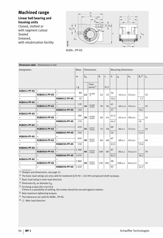
94 WF 1 Schaeffler Technologies
Machined rangeLinear ball bearing and housing unitsClosed, slotted orwith segment cutoutSealedGreased,with relubrication facility
KGBA..-PP-AS
120
184
120
184
1) Designs and dimensions, see page 31.2) The basic load ratings are only valid for hardened (670 HV + 165 HV) and ground shaft raceways.3) Basic load rating in main load direction.4) Dimension B2 on diameter FW.5) For fixing screws ISO 4762-8.8.
If there is a possibility of settling, the screws should be secured against rotation.6) Note maximum tightening torques.7) The tolerances are valid for KGBA..-PP-AS.8)
Dimension table · Dimensions in mm
Designation Mass Dimensions Mounting dimensions
m FW B L H JB A5 B24) L4
�gToler-ances7) h12
KGBA12-PP-AS – –80
12 +0,0080 42 32
3432±0,15 21±0,01
–32– KGBAS12-PP-AS –
– – KGBAO12-PP-AS 70 30,5 7,7
KGBA16-PP-AS – –120
16 +0,009–0,001 50 36
4140±0,15 25±0,01
–35– KGBAS16-PP-AS –
– – KGBAO16-PP-AS 100 37 10,1
KGBA20-PP-AS – –200
20 +0,009–0,001 60 45
47,545±0,15 30±0,01
–42– KGBAS20-PP-AS –
– – KGBAO20-PP-AS 170 44,5 10
KGBA25-PP-AS – –410
25 +0,011–0,001 74 58
6060±0,2 37±0,01
–54– KGBAS25-PP-AS –
– – KGBAO25-PP-AS 350 56 12,5
KGBA30-PP-AS – –610
30 +0,011–0,001 84 68
6768±0,2 42±0,01
–60– KGBAS30-PP-AS –
– – KGBAO30-PP-AS 530 63,5 13,6
KGBA40-PP-AS – –1 200
40 +0,013–0,002 108 80
8786±0,2 54±0,015
–78– KGBAS40-PP-AS –
– – KGBAO40-PP-AS 1 070 82,5 18,2
KGBA50-PP-AS – –1 880
50 +0,013–0,002 130 100
98108±0,2 65±0,015
–70– KGBAS50-PP-AS –
– – KGBAO50-PP-AS 1 650 93 22,7
� Main load direction
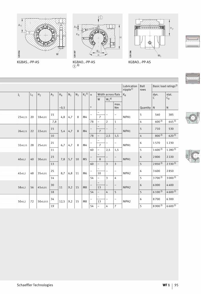
Schaeffler Technologies WF 1 95
KGBAS..-PP-AS KGBAO..-PP-AS� 8)
KGBAO..-PP-AS
120
056
120
056
120
187
120
187
120
186
120
186
Lubricationnipple1)
Ballrows
Basic load ratings2)
JL L5 H2 A3 H6 N1 N3 K55) � Width across flats K8 dyn.
Cstat.C0W W1
6)
–0,5 °max.Nm Quantity N N
23±0,15 20 18±0,0115
4,8 4,7 8 M4–
–– –
NIPA15 540 385
7
7,8 78 – 2 1 4 600 3) 445 3)
26±0,15 22 22±0,0115
5,4 4,7 8 M4–
–– –
NIPA15 710 530
7
10 78 – 2,5 1,5 4 800 3) 620 3)
32±0,15 28 25±0,0121
6,7 4,7 8 M4–
–– –
NIPA16 1 570 1 230
7
11 60 – 2,5 1,5 5 1 600 3) 1 280 3)
40±0,2 40 30±0,0123
7,8 5,7 10 M5–
–– –
NIPA16 2 800 2 220
8
13 60 – 3 3 5 2 850 3) 2 330 3)
45±0,2 48 35±0,0125
8,7 6,8 11 M6–
–– –
NIPA26 3 600 2 850
10
14 54 – 3 4 5 3 700 3) 3 000 3)
58±0,2 56 45±0,0130
11 9,2 15 M8–
–– –
NIPA26 6 000 4 400
13
18 54 – 4 5 5 6 100 3) 4 600 3)
50±0,2 72 50±0,01534
12,5 9,2 15 M8–
–– –
NIPA26 8 700 6 300
13
19 54 – 4 7 5 8 900 3) 6 600 3)
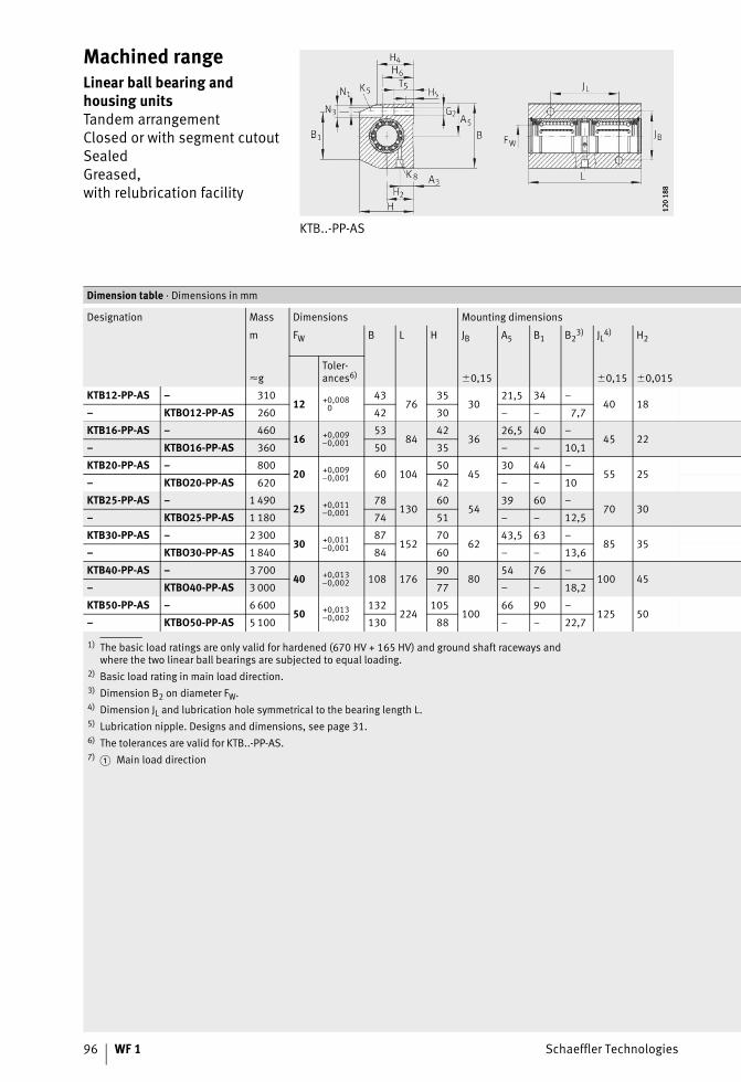
96 WF 1 Schaeffler Technologies
Machined rangeLinear ball bearing and housing unitsTandem arrangementClosed or with segment cutoutSealedGreased,with relubrication facility
KTB..-PP-AS
120
188
120
188
1) The basic load ratings are only valid for hardened (670 HV + 165 HV) and ground shaft raceways andwhere the two linear ball bearings are subjected to equal loading.
2) Basic load rating in main load direction.3) Dimension B2 on diameter FW.4) Dimension JL and lubrication hole symmetrical to the bearing length L.5) Lubrication nipple. Designs and dimensions, see page 31.6) The tolerances are valid for KTB..-PP-AS.7)
Dimension table · Dimensions in mm
Designation Mass Dimensions Mounting dimensions
m FW B L H JB A5 B1 B23) JL4) H2
�gToler-ances6) �0,15 �0,15 �0,015
KTB12-PP-AS – 31012 +0,008
043
7635
3021,5 34 –
40 18– KTBO12-PP-AS 260 42 30 – – 7,7
KTB16-PP-AS – 46016 +0,009
–0,00153
8442
3626,5 40 –
45 22– KTBO16-PP-AS 360 50 35 – – 10,1
KTB20-PP-AS – 80020 +0,009
–0,001 60 10450
4530 44 –
55 25– KTBO20-PP-AS 620 42 – – 10
KTB25-PP-AS – 1 49025 +0,011
–0,00178
13060
5439 60 –
70 30– KTBO25-PP-AS 1 180 74 51 – – 12,5
KTB30-PP-AS – 2 30030 +0,011
–0,00187
15270
6243,5 63 –
85 35– KTBO30-PP-AS 1 840 84 60 – – 13,6
KTB40-PP-AS – 3 70040 +0,013
–0,002 108 17690
8054 76 –
100 45– KTBO40-PP-AS 3 000 77 – – 18,2
KTB50-PP-AS – 6 60050 +0,013
–0,002132
224105
10066 90 –
125 50– KTBO50-PP-AS 5 100 130 88 – – 22,7
� Main load direction
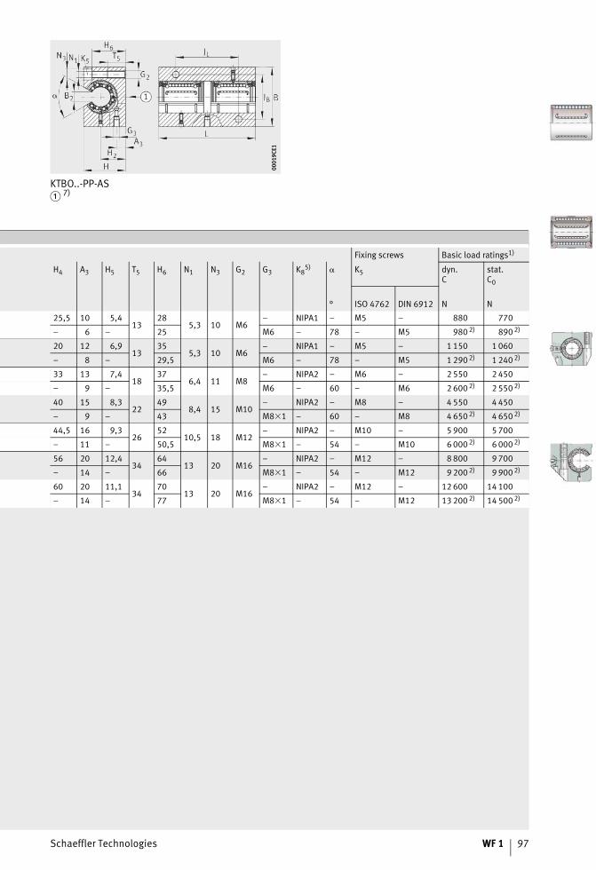
Schaeffler Technologies WF 1 97
KTBO..-PP-AS� 7)
0001
9CE1
0001
9CE1
Fixing screws Basic load ratings1)
H4 A3 H5 T5 H6 N1 N3 G2 G3 K85) � K5 dyn.
Cstat.C0
° ISO 4762 DIN 6912 N N
25,5 10 5,413
285,3 10 M6
– NIPA1 – M5 – 880 770
– 6 – 25 M6 – 78 – M5 980 2) 890 2)
20 12 6,913
355,3 10 M6
– NIPA1 – M5 – 1 150 1 060
– 8 – 29,5 M6 – 78 – M5 1 290 2) 1 240 2)
33 13 7,418
376,4 11 M8
– NIPA2 – M6 – 2 550 2 450
– 9 – 35,5 M6 – 60 – M6 2 600 2) 2 550 2)
40 15 8,322
498,4 15 M10
– NIPA2 – M8 – 4 550 4 450
– 9 – 43 M8�1 – 60 – M8 4 650 2) 4 650 2)
44,5 16 9,326
5210,5 18 M12
– NIPA2 – M10 – 5 900 5 700
– 11 – 50,5 M8�1 – 54 – M10 6 000 2) 6 000 2)
56 20 12,434
6413 20 M16
– NIPA2 – M12 – 8 800 9 700
– 14 – 66 M8�1 – 54 – M12 9 200 2) 9 900 2)
60 20 11,134
7013 20 M16
– NIPA2 – M12 – 12 600 14 100
– 14 – 77 M8�1 – 54 – M12 13 200 2) 14 500 2)

98 WF 1 Schaeffler Technologies
Machined rangeLinear ball bearing and housing unitWith flangeSealedGreased, with relubrication facility
KFB..-B-PP-AS
0001
9C35
0001
9C35
1) The basic load ratings are only valid for hardened (670 HV + 165 HV) and ground shaft raceways.2) For fixing screws ISO 4762-8.8.
If there is a possibility of settling, the screws should be secured against rotation.3) Lubrication nipple. Designs and dimensions, see page 31.
Dimension table · Dimensions in mm
Designation Mass Dimensions Mounting dimensions
m FW B L L5 L6 L7 A3
�g Tolerances
KFB12-B-PP-AS 80 12 +0,0080 40 32 22 6 4,2 11,5
KFB16-B-PP-AS 120 16 +0,009–0,001 50 36 24 8 5,2 12,5
KFB20-B-PP-AS 220 20 +0,009–0,001 60 45 30 10 6,7 15,8
KFB25-B-PP-AS 430 25 +0,011–0,001 70 58 42 12 7 22
KFB30-B-PP-AS 640 30 +0,011–0,001 80 68 50 14 8 26
KFB40-B-PP-AS 1 280 40 +0,013–0,002 100 80 59 16 9,2 30,3
KFB50-B-PP-AS 2 160 50 +0,013–0,002 130 100 75 18 11,2 38,8
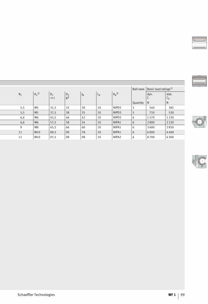
Schaeffler Technologies WF 1 99
Ball rows Basic load ratings1)
N1 K52) D1
+0,2D2g7
JB L8 K83) dyn.
Cstat.C0
Quantity N N
5,5 M5 31,5 32 30 10 NIPD3 5 540 385
5,5 M5 37,5 38 35 10 NIPD3 5 710 530
6,6 M6 45,5 46 42 10 NIPD3 6 1 570 1 230
6,6 M6 57,5 58 54 10 NIPA1 6 2 800 2 220
9 M8 65,5 66 60 10 NIPA1 6 3 600 2 850
11 M10 89,5 90 78 10 NIPA1 6 6 000 4 400
11 M10 97,5 98 98 10 NIPA2 6 8 700 6 300
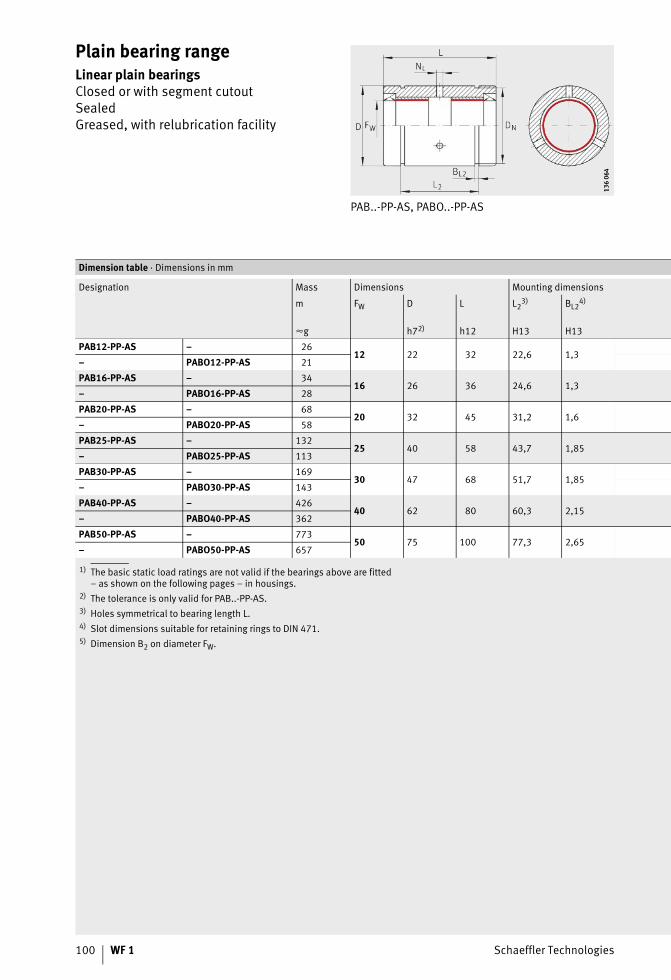
100 WF 1 Schaeffler Technologies
Plain bearing rangeLinear plain bearingsClosed or with segment cutoutSealedGreased, with relubrication facility
PAB..-PP-AS, PABO..-PP-AS
136
064
136
064
1) The basic static load ratings are not valid if the bearings above are fitted– as shown on the following pages – in housings.
2) The tolerance is only valid for PAB..-PP-AS.3) Holes symmetrical to bearing length L.4) Slot dimensions suitable for retaining rings to DIN 471.5) Dimension B2 on diameter FW.
Dimension table · Dimensions in mm
Designation Mass Dimensions Mounting dimensions
m FW D L L23) BL2
4)
�g h72) h12 H13 H13
PAB12-PP-AS – 2612 22 32 22,6 1,3
– PABO12-PP-AS 21
PAB16-PP-AS – 3416 26 36 24,6 1,3
– PABO16-PP-AS 28
PAB20-PP-AS – 6820 32 45 31,2 1,6
– PABO20-PP-AS 58
PAB25-PP-AS – 13225 40 58 43,7 1,85
– PABO25-PP-AS 113
PAB30-PP-AS – 16930 47 68 51,7 1,85
– PABO30-PP-AS 143
PAB40-PP-AS – 42640 62 80 60,3 2,15
– PABO40-PP-AS 362
PAB50-PP-AS – 77350 75 100 77,3 2,65
– PABO50-PP-AS 657
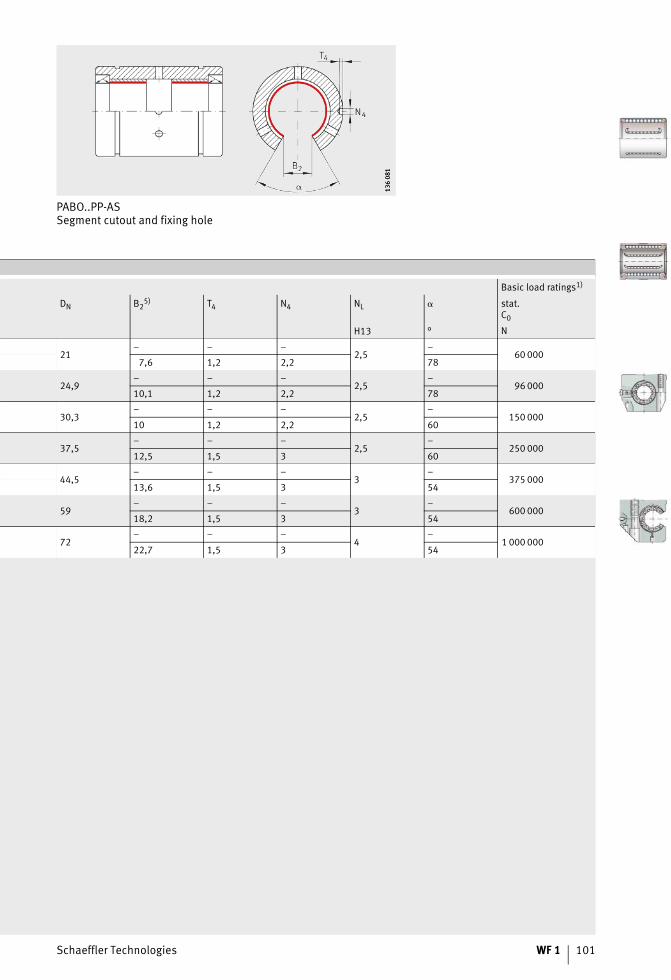
Schaeffler Technologies WF 1 101
PABO..PP-ASSegment cutout and fixing hole
136
081
136
081
Basic load ratings1)
DN B25) T4 N4 NL � stat.
C0
H13 ° N
21– – –
2,5–
60 0007,6 1,2 2,2 78
24,9– – –
2,5–
96 00010,1 1,2 2,2 78
30,3– – –
2,5–
150 00010 1,2 2,2 60
37,5– – –
2,5–
250 00012,5 1,5 3 60
44,5– – –
3–
375 00013,6 1,5 3 54
59– – –
3–
600 00018,2 1,5 3 54
72– – –
4–
1 000 00022,7 1,5 3 54
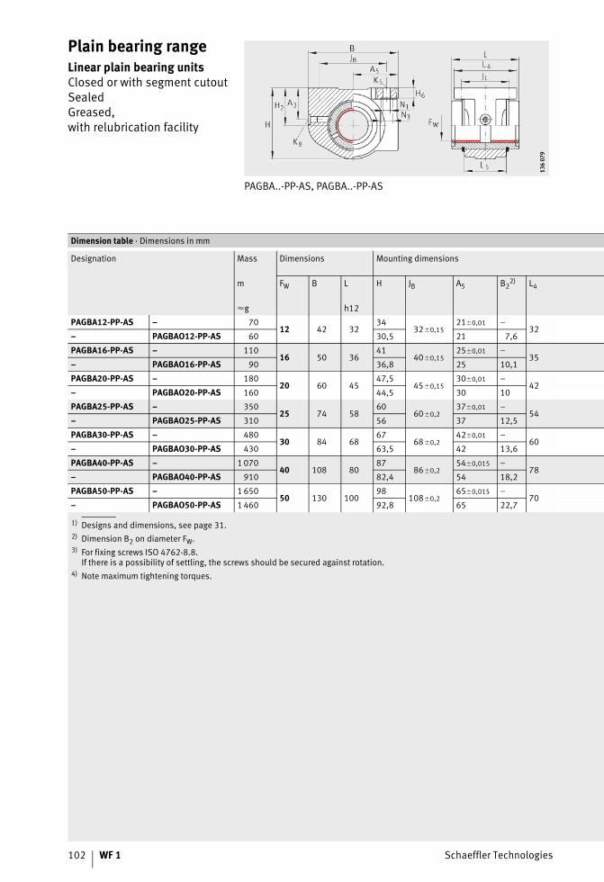
102 WF 1 Schaeffler Technologies
Plain bearing rangeLinear plain bearing unitsClosed or with segment cutoutSealedGreased,with relubrication facility
PAGBA..-PP-AS, PAGBA..-PP-AS
136
079
136
079
1) Designs and dimensions, see page 31.2) Dimension B2 on diameter FW.3) For fixing screws ISO 4762-8.8.
If there is a possibility of settling, the screws should be secured against rotation.4) Note maximum tightening torques.
Dimension table · Dimensions in mm
Designation Mass Dimensions Mounting dimensions
m FW B L H JB A5 B22) L4
�g h12
PAGBA12-PP-AS – 7012 42 32
3432�0,15
21�0,01 –32
– PAGBAO12-PP-AS 60 30,5 21 7,6
PAGBA16-PP-AS – 11016 50 36
4140�0,15
25�0,01 –35
– PAGBAO16-PP-AS 90 36,8 25 10,1
PAGBA20-PP-AS – 18020 60 45
47,545�0,15
30�0,01 –42
– PAGBAO20-PP-AS 160 44,5 30 10
PAGBA25-PP-AS – 35025 74 58
6060�0,2
37�0,01 –54
– PAGBAO25-PP-AS 310 56 37 12,5
PAGBA30-PP-AS – 48030 84 68
6768�0,2
42�0,01 –60
– PAGBAO30-PP-AS 430 63,5 42 13,6
PAGBA40-PP-AS – 1 07040 108 80
8786�0,2
54�0,015 –78
– PAGBAO40-PP-AS 910 82,4 54 18,2
PAGBA50-PP-AS – 1 65050 130 100
98108�0,2
65�0,015 –70
– PAGBAO50-PP-AS 1 460 92,8 65 22,7
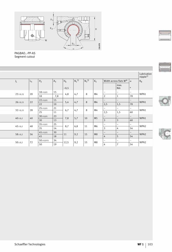
Schaeffler Technologies WF 1 103
PAGBAO..-PP-ASSegment cutout
136
078
136
078
Lubricationnipple1)
JL L5 H2 A3 H6 N13) N3
3) K5 Width across flats W4) � K8
–0,5max.Nm °
23�0,15 2018�0,01 15
4,8 4,7 8 M4– – –
NIPA118 7,8 2 1 78
26�0,15 2222�0,01 15
5,4 4,7 8 M4– – –
NIPA122 10 2,5 1,5 78
32�0,15 2825�0,01 21
6,7 4,7 8 M4– – –
NIPA125 11 2,5 1,5 60
40�0,2 4030�0,01 23
7,8 5,7 10 M5– – –
NIPA130 13 3 3 60
45�0,2 4835�0,01 25
8,7 6,8 11 M6– – –
NIPA235 14 3 4 54
58�0,2 5645�0,01 30
11 9,2 15 M8– – –
NIPA245 18 4 5 54
50�0,2 7250�0,015 34
12,5 9,2 15 M8– – –
NIPA250 19 4 7 54
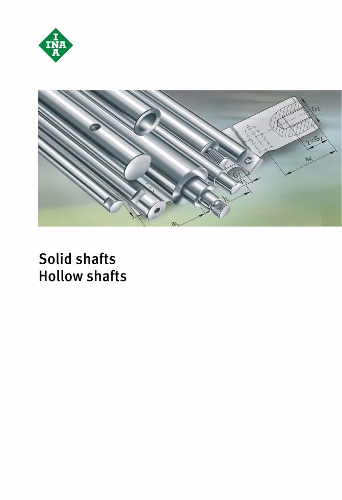
Solid shaftsHollow shafts
Schaeffler Technologies WF 1 105
Page
Solid shafts, hollow shafts
Matrix Matrix for preselection of solid and hollow shafts.................... 106
Product overview Solid shafts, hollow shafts...................................................... 108
Features High precision racewayfor economical linear guidance systems.................................. 109
Steels, hardness, surface, tolerances, lengths ........................ 109
Coatings................................................................................. 110
Available materials, coatings, tolerances ................................ 112
Solid shafts with threaded holes............................................. 113
Shafts according to customer requirements ............................ 114
Shaft machining, shaft specification ....................................... 118
Accuracy Length tolerance..................................................................... 120
Straightness value to ISO 13012............................................. 120
Ordering example,ordering designation
Solid shaft, without machining ............................................... 121
Hollow shaft, without machining............................................. 121
Solid shaft, with machining .................................................... 121
Solid shaft, according to customer requirements..................... 122
Shaft guidance system ........................................................... 123
Dimension tables Solid shafts ............................................................................ 124
Recommended threaded holes for solid shafts ........................ 125
Hollow shafts ......................................................................... 126
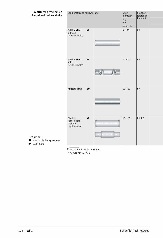
106 WF 1 Schaeffler Technologies
Matrix for preselectionof solid and hollow shafts
1) Not available for all diameters.2) For WH, Cf53 or C60.
Definition:■ Available by agreement● Available
Solid shafts and hollow shafts Shaftdiameter
Standard tolerance for shaftdLW
mm
from ... to
Solid shaftsWithoutthreaded holes
W 4 – 80 h6
Solid shaftsWiththreaded holes
W 10 – 80 h6
Hollow shafts WH 12 – 80 h7
ShaftsAccording to customer requirements
W 10 – 80 h6, h7

Schaeffler Technologies WF 1 107
Special tolerances,only for shafts madefrom quenched andtempered steel
Steel Coating1) Description
Quenched and tempered steel2)
Corrosion-resistant steel1) Hard chromium Corrotect®
Cf53 X46Cr13 X90CrMoV18 Page
j5 f7 ● ■ ■ ■ ■ 109
j5 f7 ● ■ ■ ■ ■ 113
h7 – ● – – ■ ■ 109
j5 f7 ● ■ ■ ■ ■ 114
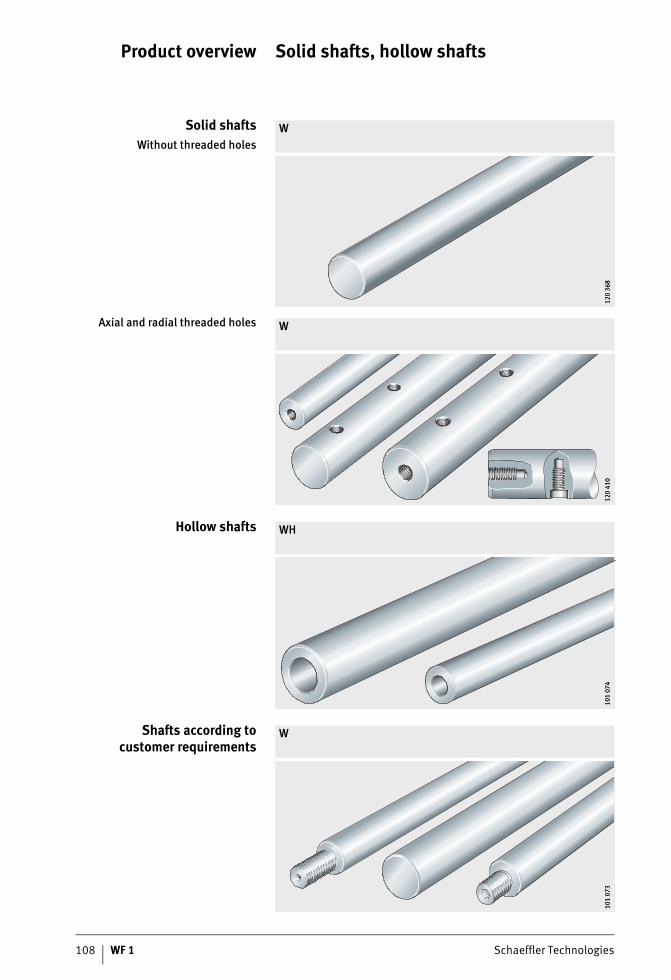
108 WF 1 Schaeffler Technologies
Product overview Solid shafts, hollow shafts
Solid shaftsWithout threaded holes
W
120
368
120
368
Axial and radial threaded holes W
120
410
120
410
Hollow shafts WH
101
074
101
074
Shafts according tocustomer requirements
W
101
073
101
073
Schaeffler Technologies WF 1 109
Solid shafts, hollow shafts
Features Solid and hollow shafts are high precision shafts made from quenched and tempered steel to rolling bearing quality and are supplied in metric sizes.Hollow shafts are particularly suitable for reduced-mass designs.For location, solid shafts can be provided with radial and axial threaded holes or can, by agreement, be produced completelyin accordance with a customer drawing, see page 113 to page 117.
High precision racewayfor economical
linear guidance systems
The material quality of the shafts guarantees high dimensional and geometrical accuracy (roundness, parallelism). Due to their high surface hardness and surface quality, the shafts are highly suitable as precision raceways for linear ball bearings.High precision shafts are also suitable as guide rods for plain bushes, as stretch and levelling rollers and in the constructionof equipment and automatic machinery.They can be combined with linear ball bearings, yoke type, stud type, ball bearing and profiled track rollers to give linear guidance systems that are rigid, precise, economical and ready to fit, with high load carrying capacity and a long operating life.
Steels, hardness, surface,tolerances, lengths
Shafts made from Cf53 (material number 1.1213) are induction hardened and ground; the surface hardness is 670 HV + 165 HV (59 HRC + 6 HRC).Hollow shafts are only available made from quenched and tempered steel.
Shafts made fromcorrosion-resistant steel toISO 683-17 and EN 10880
As an alternative to quenched and tempered steel, solid shafts are also available in corrosion-resistant steels, for exampleX46Cr13 (material number 1.4034) or X90CrMoV18 (material number 1.4112). The surface hardness in the case of X46 is 520 HV + 115 HV (52 HRC + 4 HRC). The surface hardness in the case of X90 is 580 HV + 85 HV (54 HRC + 4 HRC).These steels are particularly suitable for use in the foodstuffs industry, medical equipment and semiconductor technology.The suffix is X46 or X90.Due to the hardness curve, shafts made from the materials X46Cr13 and X90CrMoV18 have only limited corrosion resistance on the end faces. This also applies to any soft-annealed areas.
110 WF 1 Schaeffler Technologies
Solid shafts, hollow shafts
Hardness, surface,tolerances, lengths
A uniform hardening depth will ensure a smooth transition fromthe hardened surface layer to the tough, normally annealed core, which can support bending stresses.The standard surface is Ra 0,3.Solid shafts have the normal tolerance h6, while hollow shafts have h7.High precision shafts are available in single piece lengthsup to 6 000 mm. Longer shafts are available by agreement andare assembled (with mortice and tenon joints).Available steels and tolerances, see page 112.
Coatings Coatings and hard chromium coating provide optimum anti-wear and anti-corrosion protection for shafts and are optional.The characteristics of the coatings are also shown in the table Coatings, page 111.
Hard chromium coating –Anti-wear protection
Hard chromium coating is suitable for applications in which a high degree of anti-wear protection is required. The chromium coating also offers good corrosion resistance.Chromium coated shafts are to tolerance h7.The thickness of the chromium coating is at least 5 m, the hardness is 800 HV to 1050 HV.The suffix is CR.
Corrotect® –Anti-corrosion protection
Corrosion-resistant shafts are coated with the special coating Corrotect® and, for production reasons, have centring or threaded holes in the end faces.The inside diameter of hollow shafts is not coated.Corrotect® is resistant to neutral, organic fluids such as oil, brake fluid and petrol. For applications where aqueous salt solutionsin the pH range from 5 to 10 are present, Corrotect® is also suitable due to its good resistance.The suffix is RRF.Corrotect® reduces the adhesion of weld spatter.Corrotect® can be worn away by contact seals.The coating is not permitted for direct contact with foodstuffs andis not suitable in abrasive ambient media.
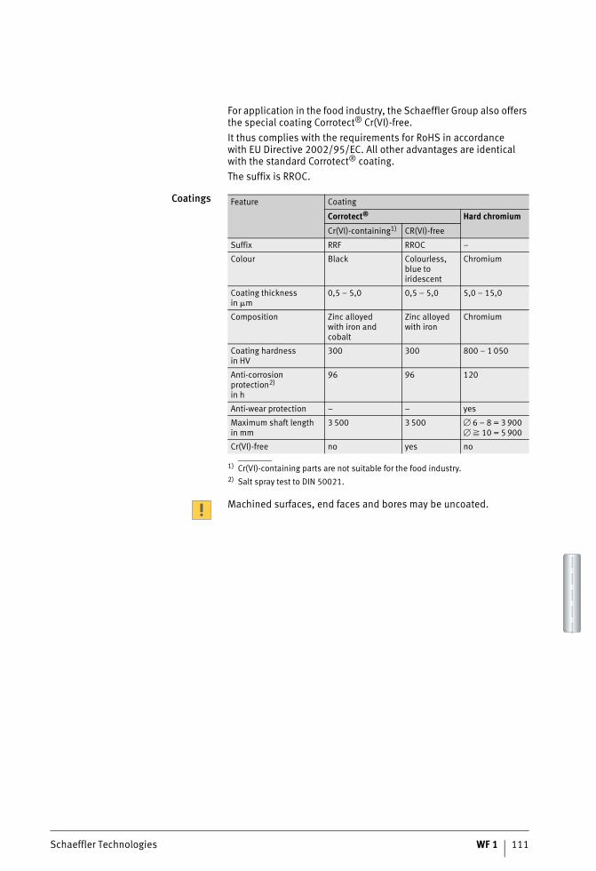
Schaeffler Technologies WF 1 111
For application in the food industry, the Schaeffler Group also offers the special coating Corrotect® Cr(VI)-free.It thus complies with the requirements for RoHS in accordancewith EU Directive 2002/95/EC. All other advantages are identical with the standard Corrotect® coating.The suffix is RROC.
Coatings
1) Cr(VI)-containing parts are not suitable for the food industry.2) Salt spray test to DIN 50021.
Machined surfaces, end faces and bores may be uncoated.
Feature Coating
Corrotect® Hard chromium
Cr(VI)-containing1) CR(VI)-free
Suffix RRF RROC –
Colour Black Colourless,blue to iridescent
Chromium
Coating thicknessin m
0,5 – 5,0 0,5 – 5,0 5,0 – 15,0
Composition Zinc alloyedwith iron and cobalt
Zinc alloyed with iron
Chromium
Coating hardnessin HV
300 300 800 – 1 050
Anti-corrosion protection2)
in h
96 96 120
Anti-wear protection – – yes
Maximum shaft lengthin mm
3 500 3 500 � 6 – 8 = 3 900� � 10 = 5 900
Cr(VI)-free no yes no
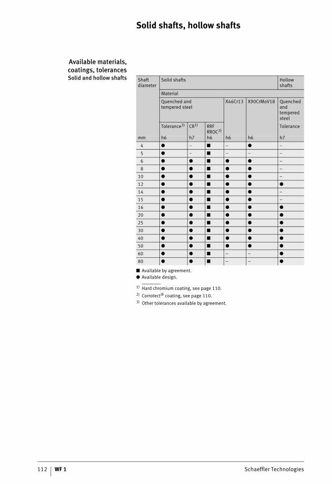
112 WF 1 Schaeffler Technologies
Solid shafts, hollow shafts
Available materials,coatings, tolerancesSolid and hollow shafts
1) Hard chromium coating, see page 110.2) Corrotect® coating, see page 110.3) Other tolerances available by agreement.
Shaft diameter
Solid shafts Hollow shafts
Material
Quenched andtempered steel
X46Cr13 X90CrMoV18 Quenched andtempered steel
Tolerance3) CR1) RRF RROC2)
Tolerance
mm h6 h7 h6 h6 h6 h7
4 ● – ■ – ● –
5 ● – ■ – – –
6 ● ● ■ ● ● –
8 ● ● ■ ● ● –
10 ● ● ■ ● ● –
12 ● ● ■ ● ● ●
14 ● ● ■ ● ● –
15 ● ● ■ ● ● –
16 ● ● ■ ● ● ●
20 ● ● ■ ● ● ●
25 ● ● ■ ● ● ●
30 ● ● ■ ● ● ●
40 ● ● ■ ● ● ●
50 ● ● ■ ● ● ●
60 ● ● ■ – – ●
80 ● ● ■ – – ●
■ Available by agreement.● Available design.
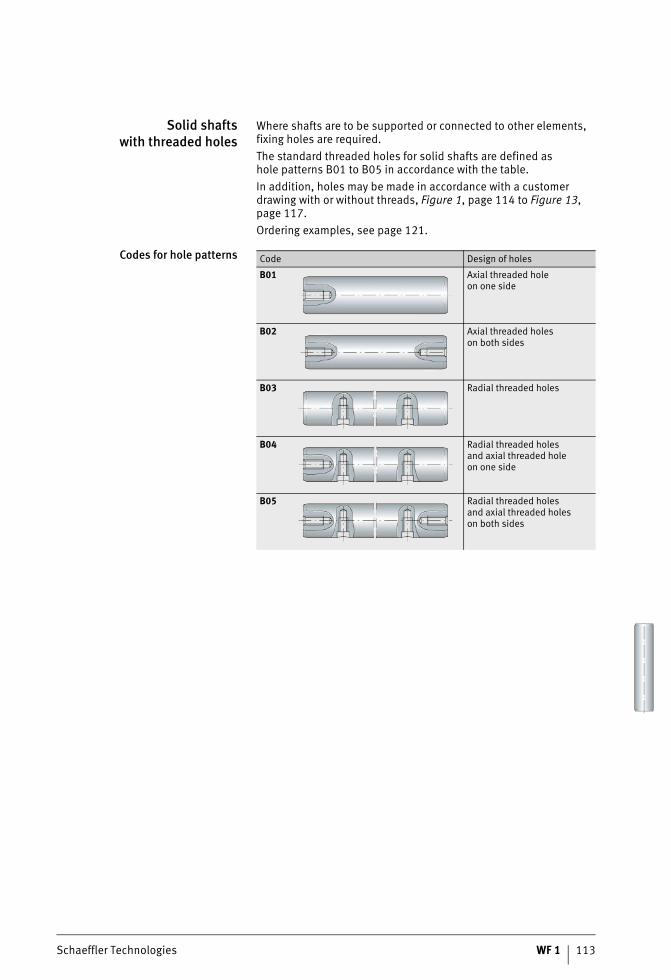
Schaeffler Technologies WF 1 113
Solid shaftswith threaded holes
Where shafts are to be supported or connected to other elements, fixing holes are required.The standard threaded holes for solid shafts are defined ashole patterns B01 to B05 in accordance with the table.In addition, holes may be made in accordance with a customer drawing with or without threads, Figure 1, page 114 to Figure 13, page 117.Ordering examples, see page 121.
Codes for hole patterns Code Design of holes
B01 Axial threaded holeon one side
B02 Axial threaded holeson both sides
B03 Radial threaded holes
B04 Radial threaded holesand axial threaded holeon one side
B05 Radial threaded holesand axial threaded holeson both sides

114 WF 1 Schaeffler Technologies
Solid shafts, hollow shafts
Shafts according tocustomer requirements
In order to place enquiries for special shafts, please useyour own drawing or copy our templates and complete usingthe required values, Figure 1 to Figure 13, page 117.
Figure 1Radial holes
with and without threads 120
464
120
464
� Diameter toDIN 336 or DIN 13
Figure 2Internal threaded hole,
on one or both sides 120
465a
120
465a
� For threaded hole with centring holeDIN 332-D recommended
Figure 3Internal threaded hole
with centring hole 120
466a
120
466a
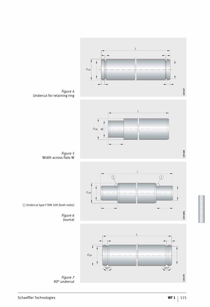
Schaeffler Technologies WF 1 115
Figure 4Undercut for retaining ring 12
0 46
712
0 46
7
Figure 5Width across flats W 12
0 46
812
0 46
8
� Undercut type F DIN 509 (both sides)
Figure 6Journal 12
0 46
9a12
0 46
9a
Figure 790° undercut 12
0 47
012
0 47
0
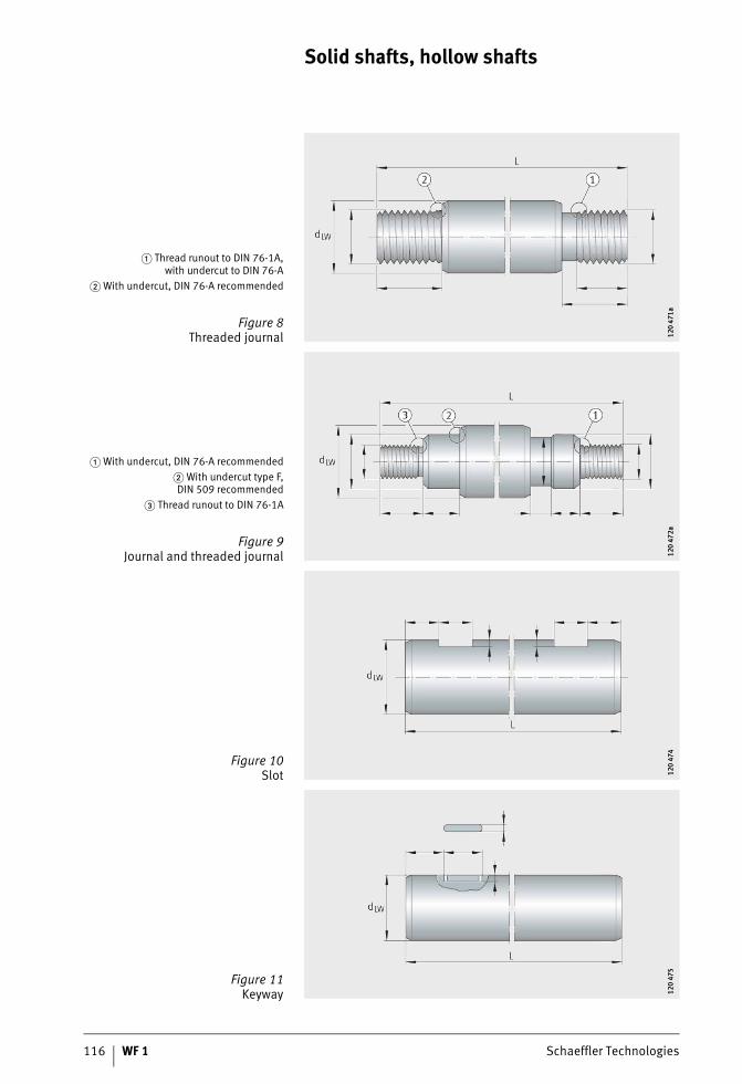
116 WF 1 Schaeffler Technologies
Solid shafts, hollow shafts
� Thread runout to DIN 76-1A,with undercut to DIN 76-A
� With undercut, DIN 76-A recommended
Figure 8Threaded journal 12
0 47
1a12
0 47
1a
� With undercut, DIN 76-A recommended� With undercut type F,DIN 509 recommended
� Thread runout to DIN 76-1A
Figure 9Journal and threaded journal 12
0 47
2a12
0 47
2a
Figure 10Slot 12
0 47
412
0 47
4
Figure 11Keyway 12
0 47
512
0 47
5
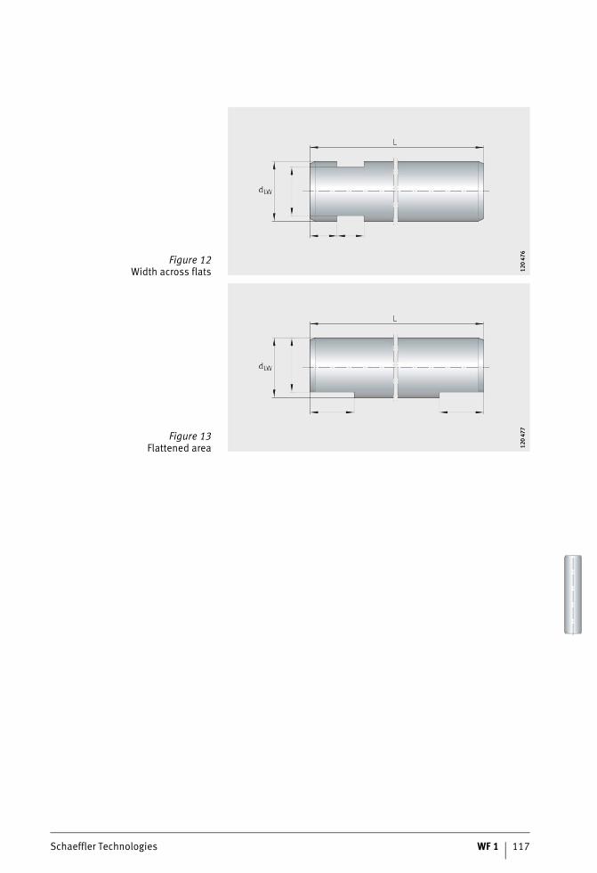
Schaeffler Technologies WF 1 117
Figure 12Width across flats 12
0 47
612
0 47
6
Figure 13Flattened area 12
0 47
712
0 47
7
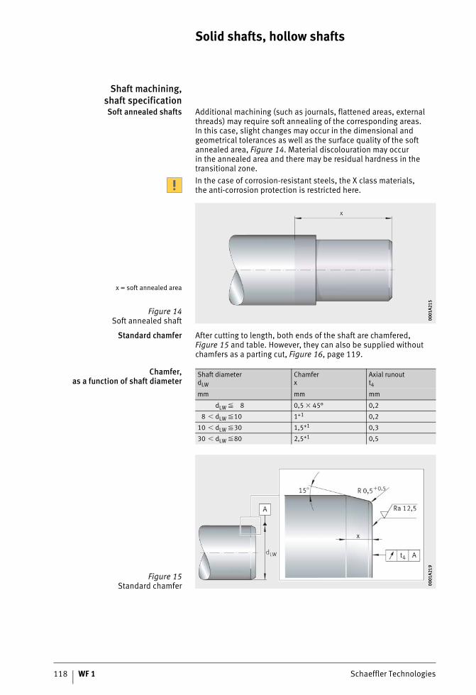
118 WF 1 Schaeffler Technologies
Solid shafts, hollow shafts
Shaft machining,shaft specificationSoft annealed shafts Additional machining (such as journals, flattened areas, external
threads) may require soft annealing of the corresponding areas.In this case, slight changes may occur in the dimensional and geometrical tolerances as well as the surface quality of the soft annealed area, Figure 14. Material discolouration may occurin the annealed area and there may be residual hardness in the transitional zone.In the case of corrosion-resistant steels, the X class materials,the anti-corrosion protection is restricted here.
Standard chamfer After cutting to length, both ends of the shaft are chamfered, Figure 15 and table. However, they can also be supplied without chamfers as a parting cut, Figure 16, page 119.
Chamfer,as a function of shaft diameter
x = soft annealed area
Figure 14Soft annealed shaft 00
01A2
1500
01A2
15
Shaft diameterdLW
Chamferx
Axial runoutt4
mm mm mm
dLW � 8 0,5 � 45° 0,2
8 � dLW �10 1+1 0,2
10 � dLW �30 1,5+1 0,3
30 � dLW �80 2,5+1 0,5
Figure 15Standard chamfer 00
01A2
1900
01A2
19
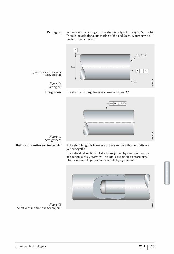
Schaeffler Technologies WF 1 119
Parting cut In the case of a parting cut, the shaft is only cut to length, Figure 16. There is no additional machining of the end faces. A burr may be present. The suffix is T.
Straightness The standard straightness is shown in Figure 17.
Shafts with mortice and tenon joint If the shaft length is in excess of the stock length, the shafts are joined together.The individual sections of shafts are joined by means of morticeand tenon joints, Figure 18. The joints are marked accordingly.Shafts screwed together are available by agreement.
t4 = axial runout tolerance,table, page 118
Figure 16Parting cut 00
01A2
1A00
01A2
1A
Figure 17Straightness 00
01A2
1B00
01A2
1B
Figure 18Shaft with mortice and tenon joint 00
01A2
1C00
01A2
1C
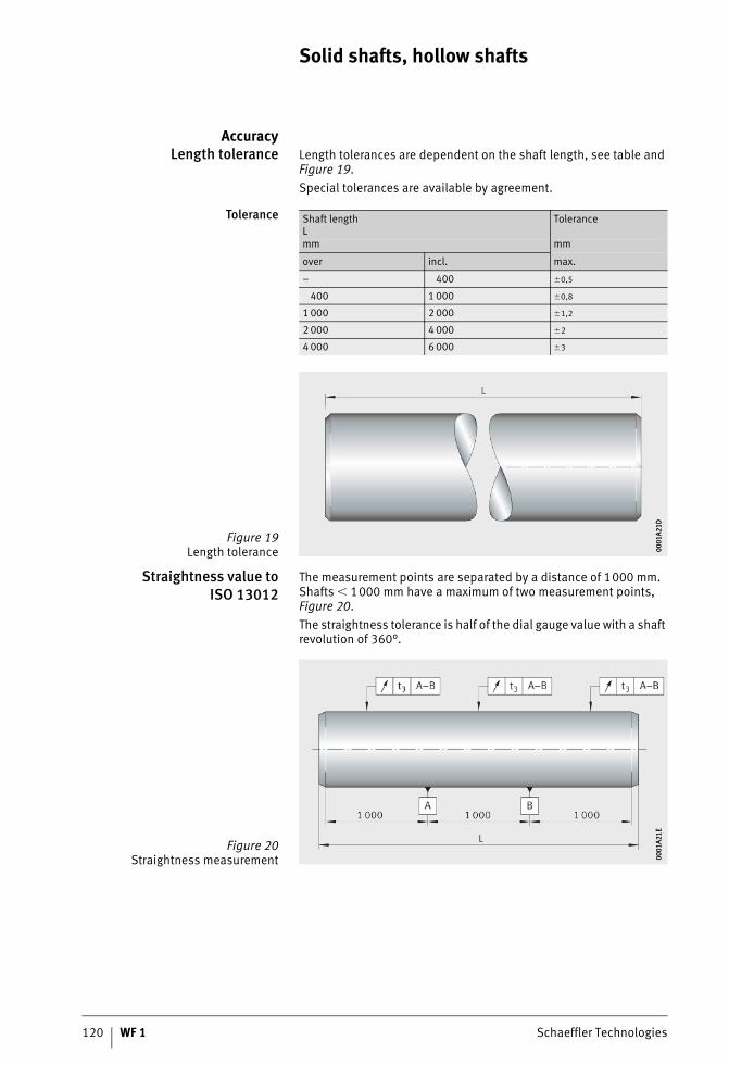
120 WF 1 Schaeffler Technologies
Solid shafts, hollow shafts
AccuracyLength tolerance Length tolerances are dependent on the shaft length, see table and
Figure 19.Special tolerances are available by agreement.
Tolerance
Straightness value toISO 13012
The measurement points are separated by a distance of 1000 mm. Shafts � 1000 mm have a maximum of two measurement points, Figure 20.The straightness tolerance is half of the dial gauge value with a shaft revolution of 360°.
Shaft lengthL
Tolerance
mm mm
over incl. max.
– 400 �0,5
400 1 000 �0,8
1 000 2 000 �1,2
2 000 4 000 �2
4 000 6 000 �3
Figure 19Length tolerance 00
01A2
1D00
01A2
1D
Figure 20Straightness measurement 00
01A2
1E00
01A2
1E
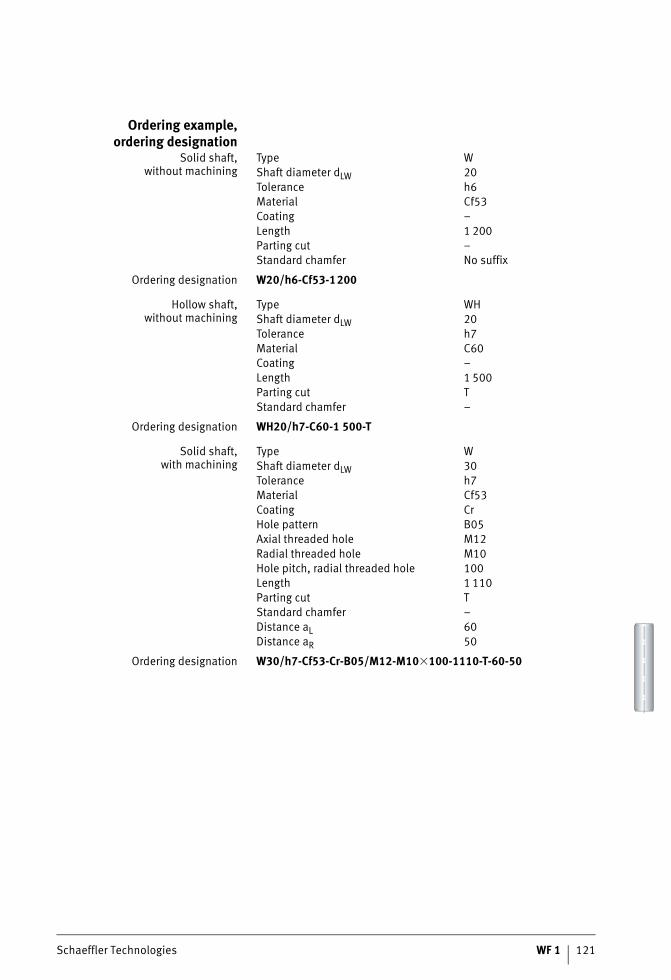
Schaeffler Technologies WF 1 121
Ordering example,ordering designation
Solid shaft,without machining
Ordering designation W20/h6-Cf53-1200
Hollow shaft,without machining
Ordering designation WH20/h7-C60-1 500-T
Solid shaft,with machining
Ordering designation W30/h7-Cf53-Cr-B05/M12-M10�100-1110-T-60-50
Type WShaft diameter dLW 20Tolerance h6Material Cf53Coating –Length 1 200Parting cut –Standard chamfer No suffix
Type WHShaft diameter dLW 20Tolerance h7Material C60Coating –Length 1 500Parting cut TStandard chamfer –
Type WShaft diameter dLW 30Tolerance h7Material Cf53Coating CrHole pattern B05Axial threaded hole M12Radial threaded hole M10Hole pitch, radial threaded hole 100Length 1 110Parting cut TStandard chamfer –Distance aL 60Distance aR 50
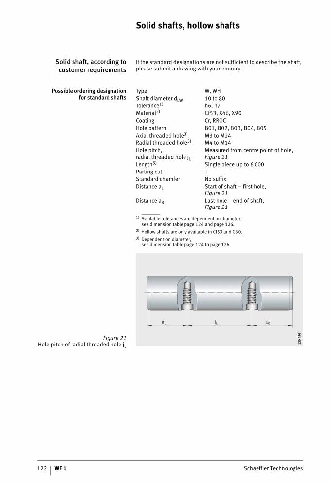
122 WF 1 Schaeffler Technologies
Solid shafts, hollow shafts
Solid shaft, according tocustomer requirements
If the standard designations are not sufficient to describe the shaft, please submit a drawing with your enquiry.
Possible ordering designationfor standard shafts
1) Available tolerances are dependent on diameter,see dimension table page 124 and page 126.
2) Hollow shafts are only available in Cf53 and C60.3) Dependent on diameter,
see dimension table page 124 to page 126.
Type W, WHShaft diameter dLW 10 to 80Tolerance1) h6, h7Material2) Cf53, X46, X90Coating Cr, RROCHole pattern B01, B02, B03, B04, B05Axial threaded hole3) M3 to M24Radial threaded hole3) M4 to M14Hole pitch,radial threaded hole jL
Measured from centre point of hole,Figure 21
Length3) Single piece up to 6 000Parting cut TStandard chamfer No suffixDistance aL Start of shaft – first hole,
Figure 21Distance aR Last hole – end of shaft,
Figure 21
Figure 21Hole pitch of radial threaded hole jL 12
0 49
012
0 49
0
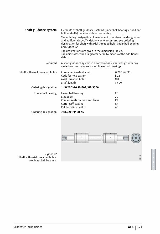
Schaeffler Technologies WF 1 123
Shaft guidance system Elements of shaft guidance systems (linear ball bearings, solid and hollow shafts) must be ordered separately.The ordering designation of an element comprises the designation and additional specific data – where necessary, see ordering designation for shaft with axial threaded hole, linear ball bearing and Figure 22.The designations are given in the dimension tables.The unit is described in greater detail by means of the additional data.
Required A shaft guidance system in a corrosion-resistant design with two sealed and corrosion-resistant linear ball bearings.
Shaft with axial threaded holes
Ordering designation 1�W20/h6-X90-B02/M8-3500
Linear ball bearing
Ordering designation 2�KB20-PP-RR-AS
Corrosion-resistant shaft W20/h6-X90Code for hole pattern B02Axial threaded hole M8Shaft length 3 500
Linear ball bearing KBSize code 20Contact seals on both end faces PPCorrotect® coating RRRelubrication facility AS
Figure 22Shaft with axial threaded holes,
two linear ball bearings 120
310
120
310
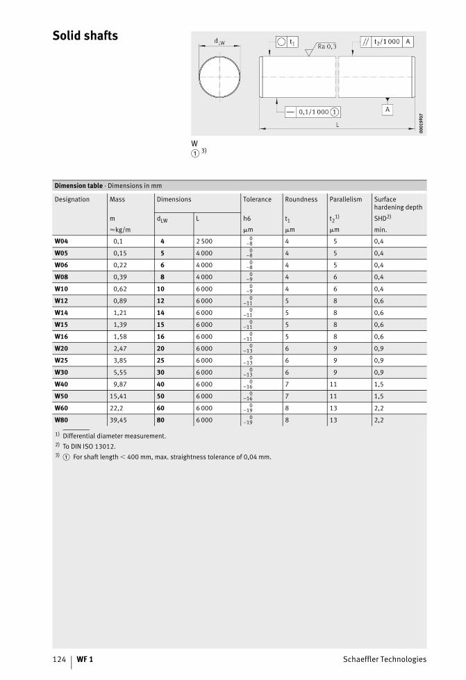
124 WF 1 Schaeffler Technologies
Solid shafts
W� 3)
0001
9F07
0001
9F07
1) Differential diameter measurement.2) To DIN ISO 13012.3)
Dimension table · Dimensions in mm
Designation Mass Dimensions Tolerance Roundness Parallelism Surfacehardening depth
m dLW L t1 t21) SHD2)h6
�kg/m m m m min.
W04 0,1 4 2 500 0–8 4 5 0,4
W05 0,15 5 4 000 0–8 4 5 0,4
W06 0,22 6 4 000 0–8 4 5 0,4
W08 0,39 8 4 000 0–9 4 6 0,4
W10 0,62 10 6 000 0–9 4 6 0,4
W12 0,89 12 6 000 0–11 5 8 0,6
W14 1,21 14 6 000 0–11 5 8 0,6
W15 1,39 15 6 000 0–11 5 8 0,6
W16 1,58 16 6 000 0–11 5 8 0,6
W20 2,47 20 6 000 0–13 6 9 0,9
W25 3,85 25 6 000 0–13 6 9 0,9
W30 5,55 30 6 000 0–13 6 9 0,9
W40 9,87 40 6 000 0–16 7 11 1,5
W50 15,41 50 6 000 0–16 7 11 1,5
W60 22,2 60 6 000 0–19 8 13 2,2
W80 39,45 80 6 000 0–19 8 13 2,2
� For shaft length � 400 mm, max. straightness tolerance of 0,04 mm.
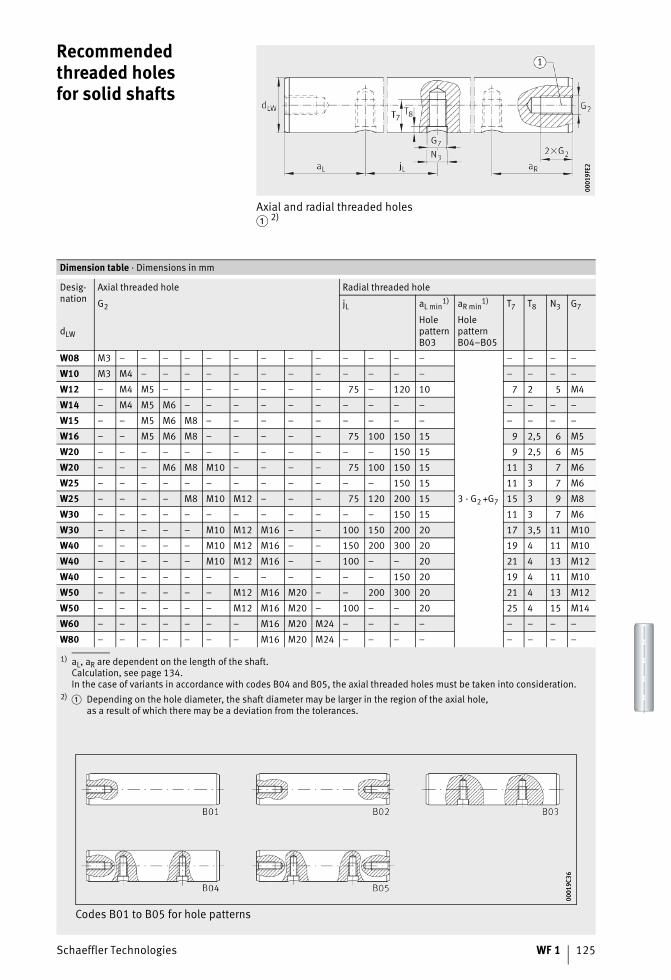
Schaeffler Technologies WF 1 125
Recommendedthreaded holesfor solid shafts
Axial and radial threaded holes� 2)
0001
9FE2
0001
9FE2
1) aL, aR are dependent on the length of the shaft.Calculation, see page 134.In the case of variants in accordance with codes B04 and B05, the axial threaded holes must be taken into consideration.
2)
Dimension table · Dimensions in mm
Desig-nation
Axial threaded hole Radial threaded hole
G2 jL aL min1) aR min
1) T7 T8 N3 G7
dLW
HolepatternB03
HolepatternB04–B05
W08 M3 – – – – – – – – – – – – –
3 · G2 +G7
– – – –
W10 M3 M4 – – – – – – – – – – – – – – – –
W12 – M4 M5 – – – – – – – 75 – 120 10 7 2 5 M4
W14 – M4 M5 M6 – – – – – – – – – – – – – –
W15 – – M5 M6 M8 – – – – – – – – – – – – –
W16 – – M5 M6 M8 – – – – – 75 100 150 15 9 2,5 6 M5
W20 – – – – – – – – – – – – 150 15 9 2,5 6 M5
W20 – – – M6 M8 M10 – – – – 75 100 150 15 11 3 7 M6
W25 – – – – – – – – – – – – 150 15 11 3 7 M6
W25 – – – – M8 M10 M12 – – – 75 120 200 15 15 3 9 M8
W30 – – – – – – – – – – – – 150 15 11 3 7 M6
W30 – – – – – M10 M12 M16 – – 100 150 200 20 17 3,5 11 M10
W40 – – – – – M10 M12 M16 – – 150 200 300 20 19 4 11 M10
W40 – – – – – M10 M12 M16 – – 100 – – 20 21 4 13 M12
W40 – – – – – – – – – – – – 150 20 19 4 11 M10
W50 – – – – – – M12 M16 M20 – – 200 300 20 21 4 13 M12
W50 – – – – – – M12 M16 M20 – 100 – – 20 25 4 15 M14
W60 – – – – – – – M16 M20 M24 – – – – – – – –
W80 – – – – – – – M16 M20 M24 – – – – – – – –
� Depending on the hole diameter, the shaft diameter may be larger in the region of the axial hole,as a result of which there may be a deviation from the tolerances.
Codes B01 to B05 for hole patterns
0001
9C36
0001
9C36
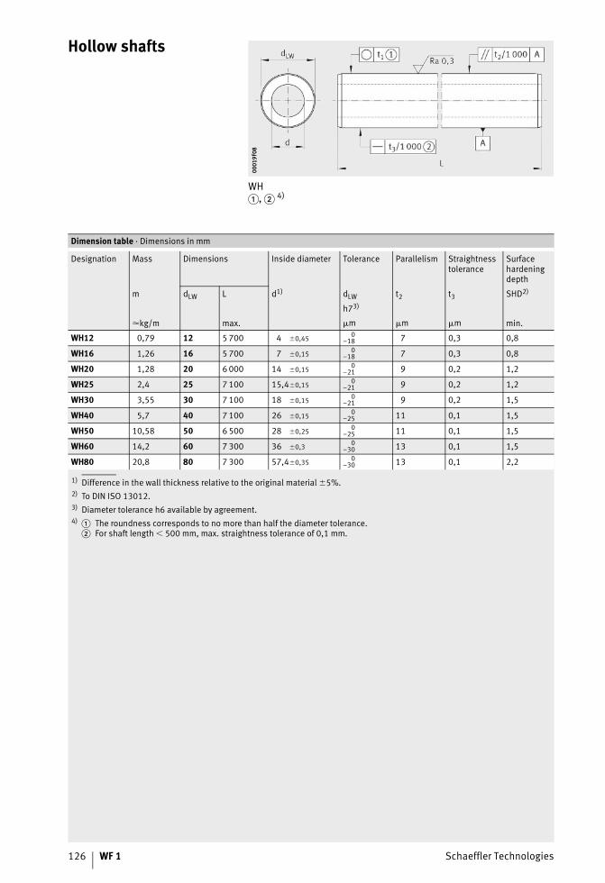
126 WF 1 Schaeffler Technologies
Hollow shafts
WH�, � 4)
0001
9F08
0001
9F08
1) Difference in the wall thickness relative to the original material �5%.2) To DIN ISO 13012.3) Diameter tolerance h6 available by agreement.4)
Dimension table · Dimensions in mm
Designation Mass Dimensions Inside diameter Tolerance Parallelism Straightnesstolerance
Surfacehardeningdepth
m dLW L d1) dLW t2 t3 SHD2)
h73)
�kg/m max. m m m min.
WH12 0,79 12 5 700 4 �0,45 0–18 7 0,3 0,8
WH16 1,26 16 5 700 7 �0,15 0–18 7 0,3 0,8
WH20 1,28 20 6 000 14 �0,15 0–21 9 0,2 1,2
WH25 2,4 25 7 100 15,4�0,15 0–21 9 0,2 1,2
WH30 3,55 30 7 100 18 �0,15 0–21 9 0,2 1,5
WH40 5,7 40 7 100 26 �0,15 0–25 11 0,1 1,5
WH50 10,58 50 6 500 28 �0,25 0–25 11 0,1 1,5
WH60 14,2 60 7 300 36 �0,3 0–30 13 0,1 1,5
WH80 20,8 80 7 300 57,4�0,35 0–30 13 0,1 2,2
� The roundness corresponds to no more than half the diameter tolerance.� For shaft length � 500 mm, max. straightness tolerance of 0,1 mm.

Schaeffler Technologies WF 1 127
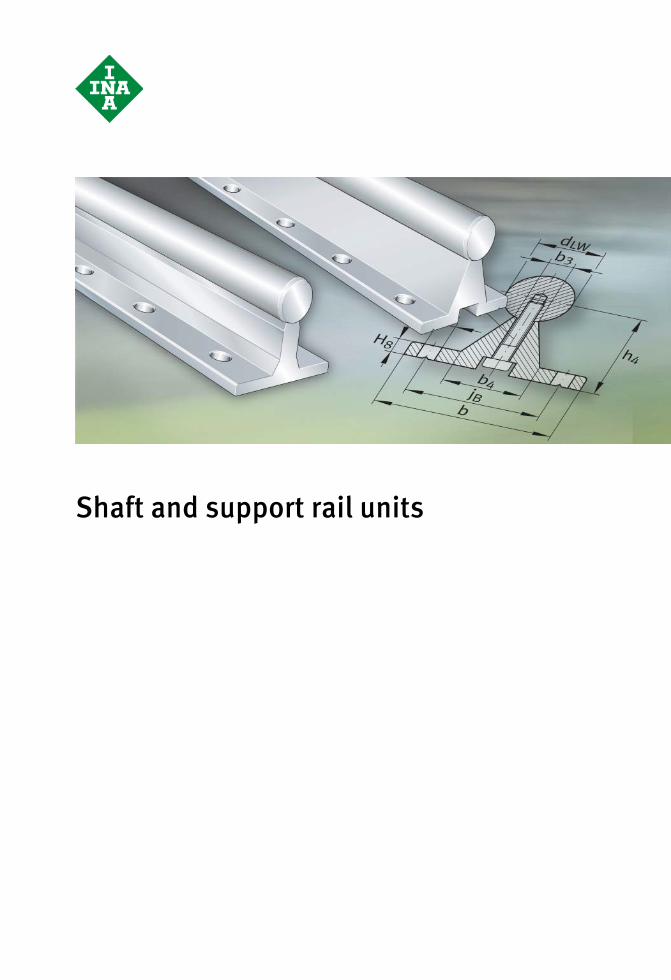
Shaft and support rail units
Schaeffler Technologies WF 1 129
Page
Shaft and support rail units
Matrix Matrix for preselection of shaft and support rail units.............. 130
Product overview Shaft and support rail units .................................................... 132
Features Multi-piece raceway shafts and shaft andsupport rail units .................................................................... 133
Design and safety guidelines Hole patterns for shaft and support rail units .......................... 134
Accuracy Length tolerances for shafts and shaft andsupport rail units .................................................................... 136
Ordering example,ordering designation
Shaft and support rail unit ...................................................... 136
Possible ordering designation for standard shaft andsupport rail units .................................................................... 136
Dimension tables Shaft and support rail units .................................................... 138
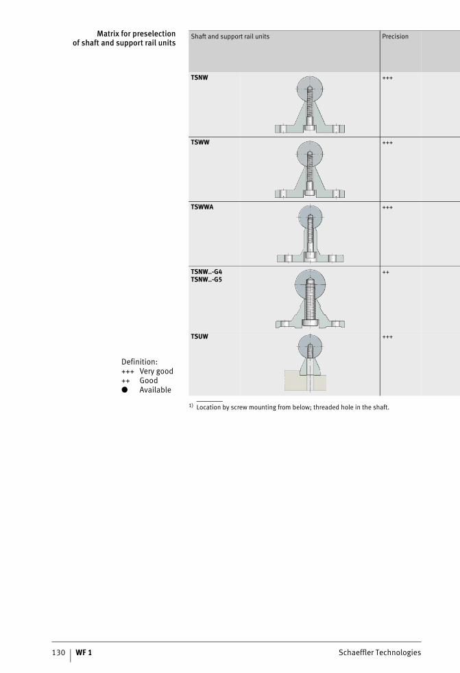
130 WF 1 Schaeffler Technologies
Matrix for preselectionof shaft and support rail units
1) Location by screw mounting from below; threaded hole in the shaft.
Definition:+++ Very good++ Good● Available
Shaft and support rail units Precision
TSNW +++
TSWW +++
TSWWA +++
TSNW..-G4TSNW..-G5
++
TSUW +++
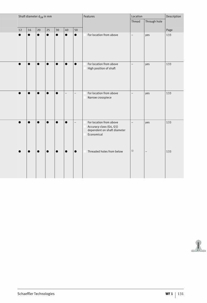
Schaeffler Technologies WF 1 131
Shaft diameter dLW in mm Features Location Description
Thread Through hole
12 16 20 25 30 40 50 Page
● ● ● ● ● ● ● ■ For location from above – yes 133
● ● ● ● ● ● ● ■ For location from above■ High position of shaft
– yes 133
● ● ● ● ● – – ■ For location from above■ Narrow crosspiece
– yes 133
● ● ● ● ● ● – ■ For location from above■ Accuracy class (G4, G5)
dependent on shaft diameter■ Economical
– yes 133
● ● ● ● ● ● ● ■ Threaded holes from below 1) – 133
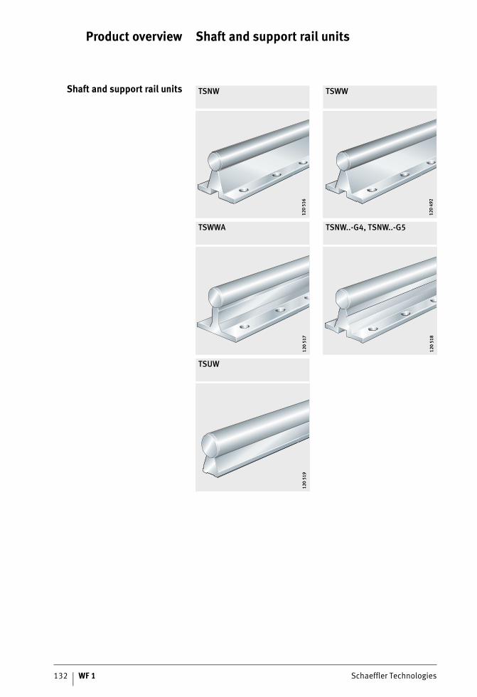
132 WF 1 Schaeffler Technologies
Product overview Shaft and support rail units
Shaft and support rail units TSNW TSWW
TSWWA TSNW..-G4, TSNW..-G5
TSUW
120
516
120
516
120
492
120
492
120
517
120
517
120
518
120
518
120
519
120
519
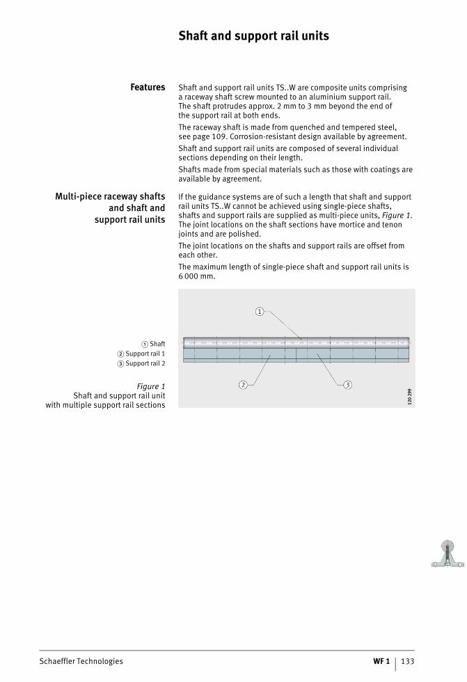
Schaeffler Technologies WF 1 133
Shaft and support rail units
Features Shaft and support rail units TS..W are composite units comprisinga raceway shaft screw mounted to an aluminium support rail.The shaft protrudes approx. 2 mm to 3 mm beyond the end ofthe support rail at both ends.The raceway shaft is made from quenched and tempered steel,see page 109. Corrosion-resistant design available by agreement.Shaft and support rail units are composed of several individual sections depending on their length.Shafts made from special materials such as those with coatings are available by agreement.
Multi-piece raceway shaftsand shaft and
support rail units
If the guidance systems are of such a length that shaft and support rail units TS..W cannot be achieved using single-piece shafts,shafts and support rails are supplied as multi-piece units, Figure 1. The joint locations on the shaft sections have mortice and tenon joints and are polished.The joint locations on the shafts and support rails are offset from each other.The maximum length of single-piece shaft and support rail units is 6 000 mm.
� Shaft� Support rail 1� Support rail 2
Figure 1Shaft and support rail unit
with multiple support rail sections 120
299
120
299
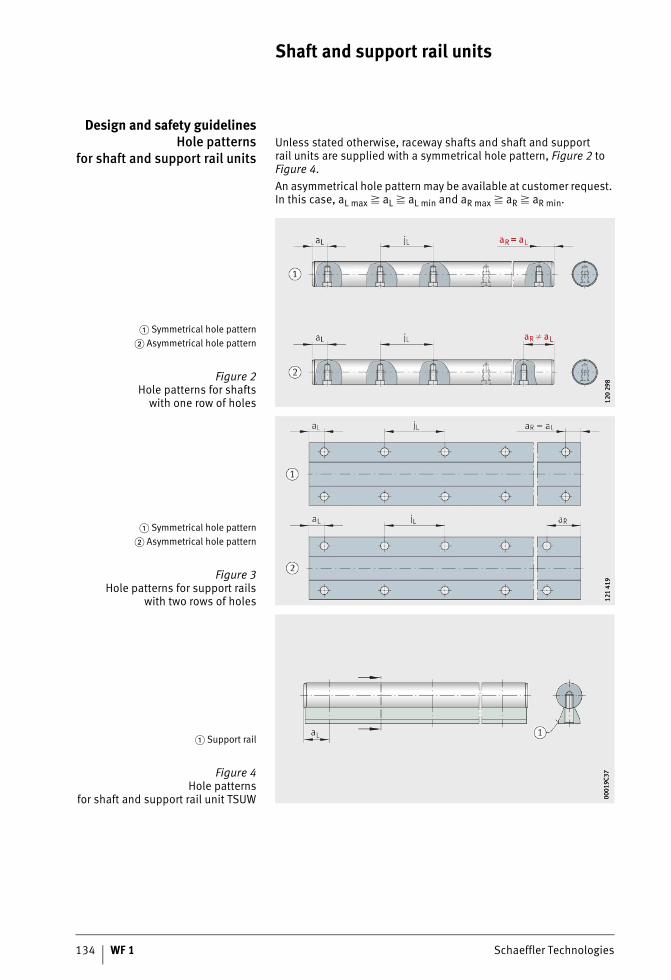
134 WF 1 Schaeffler Technologies
Shaft and support rail units
Design and safety guidelinesHole patterns
for shaft and support rail unitsUnless stated otherwise, raceway shafts and shaft and supportrail units are supplied with a symmetrical hole pattern, Figure 2 to Figure 4.An asymmetrical hole pattern may be available at customer request. In this case, aL max � aL � aL min and aR max � aR � aR min.
� Symmetrical hole pattern� Asymmetrical hole pattern
Figure 2Hole patterns for shafts
with one row of holes 120
298
120
298
� Symmetrical hole pattern� Asymmetrical hole pattern
Figure 3Hole patterns for support rails
with two rows of holes 121
419
121
419
� Support rail
Figure 4Hole patterns
for shaft and support rail unit TSUW 0001
9C37
0001
9C37
Schaeffler Technologies WF 1 135
Maximum numberof pitches between holes
The number of pitches between holes is the rounded whole number equivalent to:
The distances aL and aR are generally determined by:
For raceway shafts and shaft and support rail units witha symmetrical hole pattern:
Number of holes:
n mmMaximum possible number of pitches or recommended distance between screws on shaft and support rail units with T-slotsl mmLength of shaft and support rail unitaL, aR mmDistance between start or end of shaft and support rail unit and nearest holeaL min, aR min mmMinimum values for aL, aR according to dimension tablesaL max, aR max mmMaximum values for aL, aR according to dimension tablesjL mmDistance between holesx mmNumber of holes on shaft and support rail units with T-slots: number of screws.
If the minimum and maximum values for aL and aR are not observed, the counterbores of the holes may be intersected. The position aLfor shaft and support rail unit TSUW is shown in Figure 4, page 134.
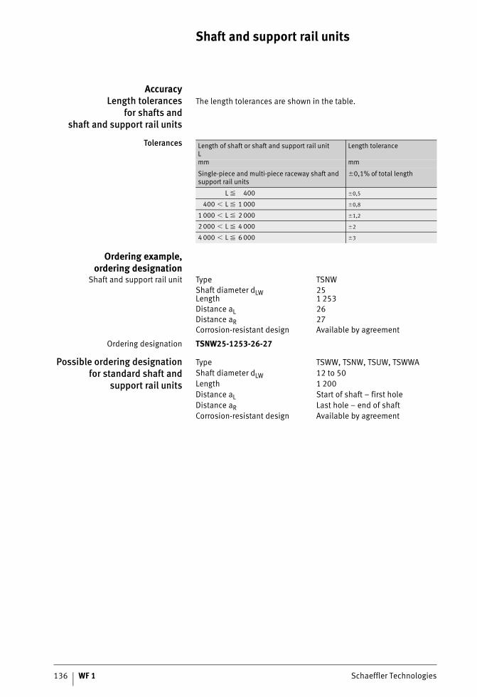
136 WF 1 Schaeffler Technologies
Shaft and support rail units
AccuracyLength tolerances
for shafts andshaft and support rail units
The length tolerances are shown in the table.
Tolerances
Ordering example,ordering designation
Shaft and support rail unit
Ordering designation TSNW25-1253-26-27
Possible ordering designationfor standard shaft and
support rail units
Length of shaft or shaft and support rail unitL
Length tolerance
mm mm
Single-piece and multi-piece raceway shaft and support rail units
�0,1% of total length
L � 400 �0,5
400 � L � 1 000 �0,8
1 000 � L � 2 000 �1,2
2 000 � L � 4 000 �2
4 000 � L � 6 000 �3
Type TSNWShaft diameter dLW 25Length 1 253Distance aL 26Distance aR 27Corrosion-resistant design Available by agreement
Type TSWW, TSNW, TSUW, TSWWAShaft diameter dLW 12 to 50Length 1 200Distance aL Start of shaft – first holeDistance aR Last hole – end of shaftCorrosion-resistant design Available by agreement

Schaeffler Technologies WF 1 137
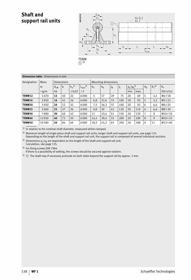
138 WF 1 Schaeffler Technologies
Shaft andsupport rail units
TSNW� 5)
0001
9C39
0001
9C39
1) In relation to the nominal shaft diameter, measured whilst clamped.2) Maximum length of single-piece shaft and support rail units; longer shaft and support rail units, see page 133.
Depending on the length of the shaft and support rail unit, the support rail is composed of several individual sections.3) Dimensions aL/aR are dependent on the length of the shaft and support rail unit.
Calculation, see page 135.4) For fixing screws DIN 7984.
If there is a possibility of settling, the screws should be secured against rotation.5)
Dimension table · Dimensions in mm
Designation Mass Dimensions Mounting dimensions
m dLW b h41) lmax
2) b3 b4 jB jL aL/aR3) H8 K3
4) K7
�g/m h6 �0,02 �3 min. max. ISO 4762
TSNW12 1 670 12 40 22 6 000 5 17 29 75 20 69 5 4,5 M4�18
TSNW16 2 950 16 45 26 6 000 6,8 22,4 33 100 20 93 5 5,5 M5�22
TSNW20 3 950 20 52 32 6 000 7,5 26,3 37 100 20 92 6 6,6 M6�25
TSNW25 5 600 25 57 36 6 000 9,8 30 42 120 20 110 6 6,6 M8�30
TSNW30 7 880 30 69 42 6 000 11 33,4 51 150 20 139 7 9 M10�35
TSNW40 12 830 40 73 50 6 000 14,5 39,4 55 200 20 189 8 9 M10�35
TSNW50 19 380 50 84 60 6 000 18,5 45,2 63 200 20 188 9 11 M12�40
� The shaft may if necessary protrude on both sides beyond the support rail by approx. 3 mm.
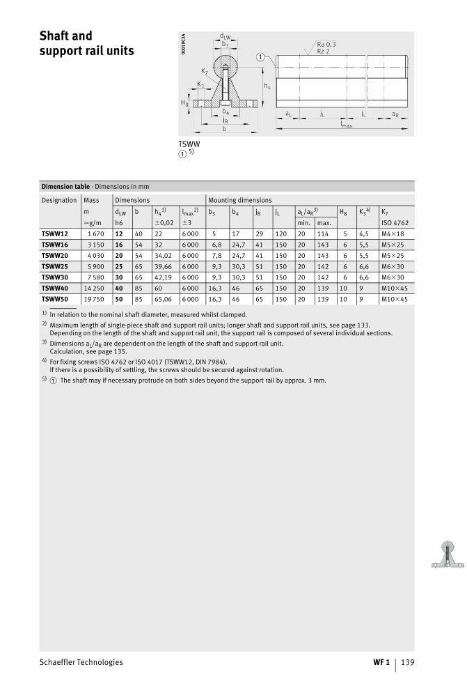
Schaeffler Technologies WF 1 139
Shaft andsupport rail units
TSWW� 5)
0001
9C3A
0001
9C3A
1) In relation to the nominal shaft diameter, measured whilst clamped.2) Maximum length of single-piece shaft and support rail units; longer shaft and support rail units, see page 133.
Depending on the length of the shaft and support rail unit, the support rail is composed of several individual sections.3) Dimensions aL/aR are dependent on the length of the shaft and support rail unit.
Calculation, see page 135.4) For fixing screws ISO 4762 or ISO 4017 (TSWW12, DIN 7984).
If there is a possibility of settling, the screws should be secured against rotation.5)
Dimension table · Dimensions in mm
Designation Mass Dimensions Mounting dimensions
m dLW b h41) lmax
2) b3 b4 jB jL aL/aR3) H8 K3
4) K7
�g/m h6 �0,02 �3 min. max. ISO 4762
TSWW12 1 670 12 40 22 6 000 5 17 29 120 20 114 5 4,5 M4�18
TSWW16 3 150 16 54 32 6 000 6,8 24,7 41 150 20 143 6 5,5 M5�25
TSWW20 4 030 20 54 34,02 6 000 7,8 24,7 41 150 20 143 6 5,5 M5�25
TSWW25 5 900 25 65 39,66 6 000 9,3 30,3 51 150 20 142 6 6,6 M6�30
TSWW30 7 580 30 65 42,19 6 000 9,3 30,3 51 150 20 142 6 6,6 M6�30
TSWW40 14 250 40 85 60 6 000 16,3 46 65 150 20 139 10 9 M10�45
TSWW50 19 750 50 85 65,06 6 000 16,3 46 65 150 20 139 10 9 M10�45
� The shaft may if necessary protrude on both sides beyond the support rail by approx. 3 mm.
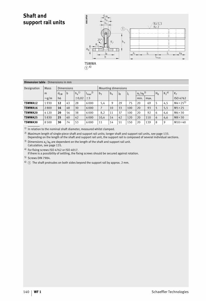
140 WF 1 Schaeffler Technologies
Shaft andsupport rail units
TSWWA� 6)
0001
9F09
0001
9F09
1) In relation to the nominal shaft diameter, measured whilst clamped.2) Maximum length of single-piece shaft and support rail units; longer shaft and support rail units, see page 133.
Depending on the length of the shaft and support rail unit, the support rail is composed of several individual sections.3) Dimensions aL/aR are dependent on the length of the shaft and support rail unit.
Calculation, see page 135.4) For fixing screws ISO 4762 or ISO 4017.
If there is a possibility of settling, the fixing screws should be secured against rotation.5) Screws DIN 7984.6)
Dimension table · Dimensions in mm
Designation Mass Dimensions Mounting dimensions
m dLW b h41) lmax
2) b3 b4 jB jL aL/aR3) H8 K3
4) K7
�g/m h6 �0,02 �3 min. max. ISO 4762
TSWWA12 1 930 12 43 28 6 000 5,4 9 29 75 20 69 5 4,5 M4�255)
TSWWA16 2 800 16 48 30 6 000 7 10 33 100 20 93 5 5,5 M5�25
TSWWA20 4 120 20 56 38 6 000 8,2 11 37 100 20 92 6 6,6 M6�30
TSWWA25 5 830 25 60 42 6 000 10,4 14 42 120 20 110 6 6,6 M8�30
TSWWA30 8 500 30 74 53 6 000 11 14 51 150 20 139 8 9 M10�40
� The shaft protrudes on both sides beyond the support rail by approx. 2 mm.
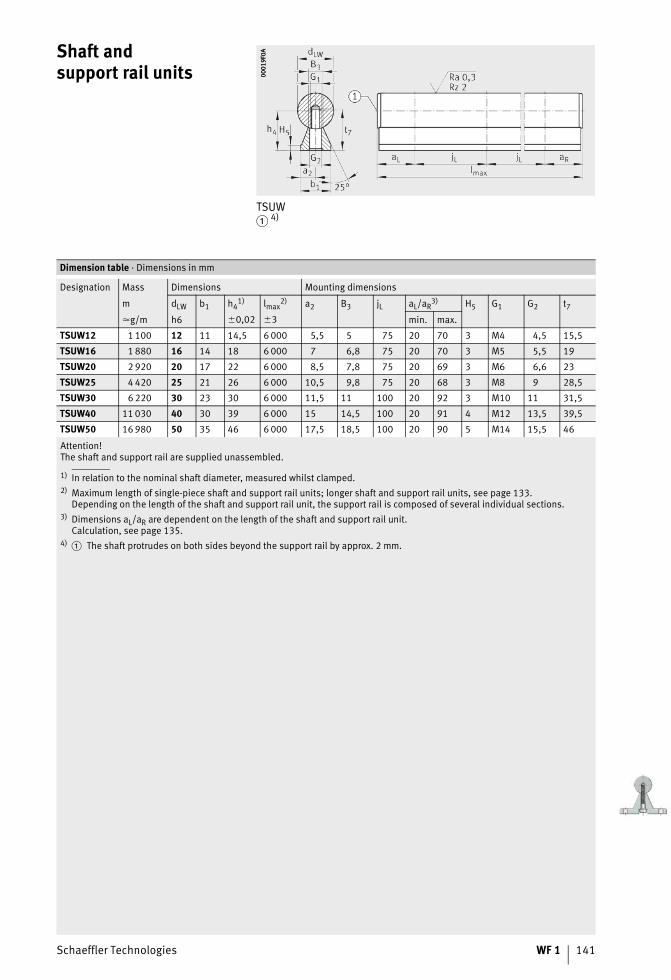
Schaeffler Technologies WF 1 141
Shaft andsupport rail units
TSUW� 4)
0001
9F0A
0001
9F0A
Attention!The shaft and support rail are supplied unassembled.
1) In relation to the nominal shaft diameter, measured whilst clamped.2) Maximum length of single-piece shaft and support rail units; longer shaft and support rail units, see page 133.
Depending on the length of the shaft and support rail unit, the support rail is composed of several individual sections.3) Dimensions aL/aR are dependent on the length of the shaft and support rail unit.
Calculation, see page 135.4)
Dimension table · Dimensions in mm
Designation Mass Dimensions Mounting dimensions
m dLW b1 h41) lmax
2) a2 B3 jL aL/aR3) H5 G1 G2 t7
�g/m h6 �0,02 �3 min. max.
TSUW12 1 100 12 11 14,5 6 000 5,5 5 75 20 70 3 M4 4,5 15,5
TSUW16 1 880 16 14 18 6 000 7 6,8 75 20 70 3 M5 5,5 19
TSUW20 2 920 20 17 22 6 000 8,5 7,8 75 20 69 3 M6 6,6 23
TSUW25 4 420 25 21 26 6 000 10,5 9,8 75 20 68 3 M8 9 28,5
TSUW30 6 220 30 23 30 6 000 11,5 11 100 20 92 3 M10 11 31,5
TSUW40 11 030 40 30 39 6 000 15 14,5 100 20 91 4 M12 13,5 39,5
TSUW50 16 980 50 35 46 6 000 17,5 18,5 100 20 90 5 M14 15,5 46
� The shaft protrudes on both sides beyond the support rail by approx. 2 mm.
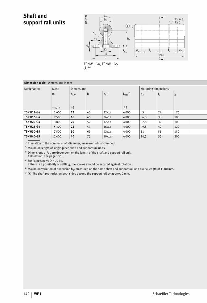
142 WF 1 Schaeffler Technologies
Shaft andsupport rail units
TSNW..-G4, TSNW..-G5� 6)
0001
9F0B
0001
9F0B
1) In relation to the nominal shaft diameter, measured whilst clamped.2) Maximum length of single-piece shaft and support rail units.3) Dimensions aL/aR are dependent on the length of the shaft and support rail unit.
Calculation, see page 135.4) For fixing screws DIN 7964.
If there is a possibility of settling, the screws should be secured against rotation.5) Maximum variation of dimension h4, measured on the same shaft and support rail unit over a length of 1000 mm.6)
Dimension table · Dimensions in mm
Designation Mass Dimensions Mounting dimensions
m dLW b h41) lmax
2) b3 jB jL
�g/m h6 �2
TSNW12-G4 1 600 12 40 22±0,1 4 000 5 29 75
TSNW16-G4 2 500 16 45 26±0,1 4 000 6,8 33 100
TSNW20-G4 3 800 20 52 32±0,1 4 000 7,8 37 100
TSNW25-G4 5 300 25 57 36±0,1 4 000 9,8 42 120
TSNW30-G5 7 500 30 69 42±0,15 4 000 11 51 150
TSNW40-G5 12 400 40 73 50±0,15 4 000 14,5 55 200
� The shaft protrudes on both sides beyond the support rail by approx. 2 mm.
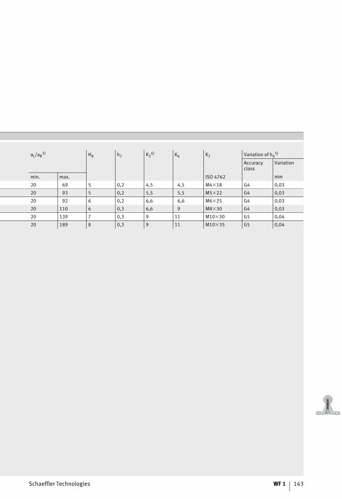
Schaeffler Technologies WF 1 143
aL/aR3) H8 h7 K3
4) K6 K7 Variation of h45)
Accuracyclass
Variation
min. max. ISO 4762 mm
20 69 5 0,2 4,5 4,5 M4�18 G4 0,03
20 93 5 0,2 5,5 5,5 M5�22 G4 0,03
20 92 6 0,2 6,6 6,6 M6�25 G4 0,03
20 110 6 0,3 6,6 9 M8�30 G4 0,03
20 139 7 0,3 9 11 M10�30 G5 0,04
20 189 8 0,3 9 11 M10�35 G5 0,04
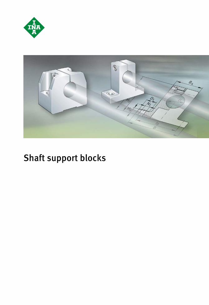
Shaft support blocks

Schaeffler Technologies WF 1 145
Page
Shaft support blocks
Matrix Matrix for preselection of shaft support blocks........................ 146
Product overview Shaft support blocks .............................................................. 148
Features .............................................................................................. 149
Dimension tables Shaft support blocks .............................................................. 150
Shaft support block with flange .............................................. 154
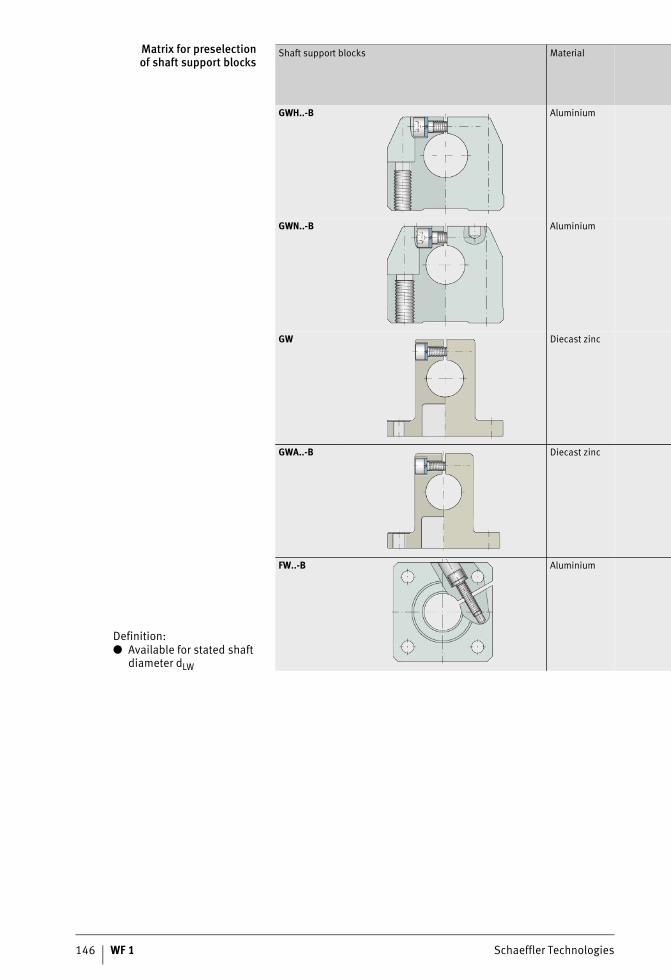
146 WF 1 Schaeffler Technologies
Matrix for preselectionof shaft support blocks
Definition:● Available for stated shaft
diameter dLW
Shaft support blocks Material
GWH..-B Aluminium
GWN..-B Aluminium
GW Diecast zinc
GWA..-B Diecast zinc
FW..-B Aluminium
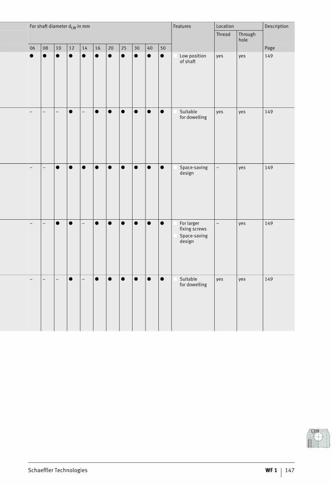
Schaeffler Technologies WF 1 147
For shaft diameter dLW in mm Features Location Description
Thread Throughhole
06 08 10 12 14 16 20 25 30 40 50 Page
● ● ● ● ● ● ● ● ● ● ● ■ Low positionof shaft
yes yes 149
– – – ● – ● ● ● ● ● ● ■ Suitablefor dowelling
yes yes 149
– – ● ● ● ● ● ● ● ● ● ■ Space-saving design
– yes 149
– – ● ● – ● ● ● ● ● ● ■ For largerfixing screws
■ Space-saving design
– yes 149
– – – ● – ● ● ● ● ● ● ■ Suitablefor dowelling
yes yes 149
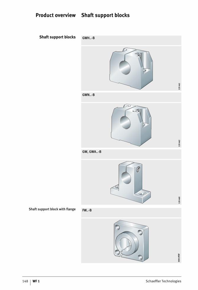
148 WF 1 Schaeffler Technologies
Product overview Shaft support blocks
Shaft support blocks GWH..-B
GWN..-B
GW, GWA..-B
120
461
120
461
120
462
120
462
120
460
120
460
Shaft support block with flange FW..-B
0001
9FD
F00
019F
DF

Schaeffler Technologies WF 1 149
Shaft support blocks
Features Shaft support blocks are used to support shafts and locate the ends of the shaft.They are suitable for all the solid and hollow shafts in this catalogue.They are made from either an aluminium alloy or pressure diecast zinc.Series GWA..-B is identical in design to series GW but is suitablefor larger fixing screws.Depending on the series, the shaft support blocks have through holes or threaded holes.
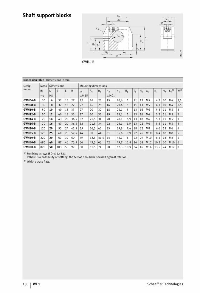
150 WF 1 Schaeffler Technologies
Shaft support blocks
GWH..-B
120
130
120
130
1) For fixing screws ISO 4762-8.8.If there is a possibility of settling, the screws should be secured against rotation.
2) Width across flats.
Dimension table · Dimensions in mm
Desig-nation
Mass Dimensions Mounting dimensions
m D B L H JB A5 B1 H2 H4 H5 T5 H6 G2 N1 N3 K51) W2)
�g H8 �0,15 �0,01
GWH06-B 30 6 32 16 27 22 16 25 15 20,6 5 11 13 M5 4,3 10 M4 2,5
GWH08-B 30 8 32 16 27 22 16 25 16 20,6 5 11 13 M5 4,3 10 M4 2,5
GWH10-B 50 10 40 18 33 27 20 32 18 25,1 5 13 16 M6 5,3 11 M5 3
GWH12-B 50 12 40 18 33 27 20 32 19 25,1 5 13 16 M6 5,3 11 M5 3
GWH14-B 70 14 43 20 36,5 32 21,5 34 20 28,1 6,9 13 18 M6 5,3 11 M5 3
GWH16-B 70 16 43 20 36,5 32 21,5 34 22 28,1 6,9 13 22 M6 5,3 11 M5 3
GWH20-B 120 20 53 24 42,5 39 26,5 40 25 29,8 7,4 18 22 M8 6,6 15 M6 4
GWH25-B 170 25 60 28 52,5 44 30 44 31 36,6 9,9 22 26 M10 8,4 18 M8 5
GWH30-B 220 30 67 30 60 49 33,5 49,5 34 42,7 8 22 29 M10 8,4 18 M8 5
GWH40-B 480 40 87 40 73,5 66 43,5 63 42 49,7 12,8 26 38 M12 10,5 20 M10 6
GWH50-B 820 50 103 50 92 80 51,5 74 50 62,3 10,9 34 46 M16 13,5 24 M12 8
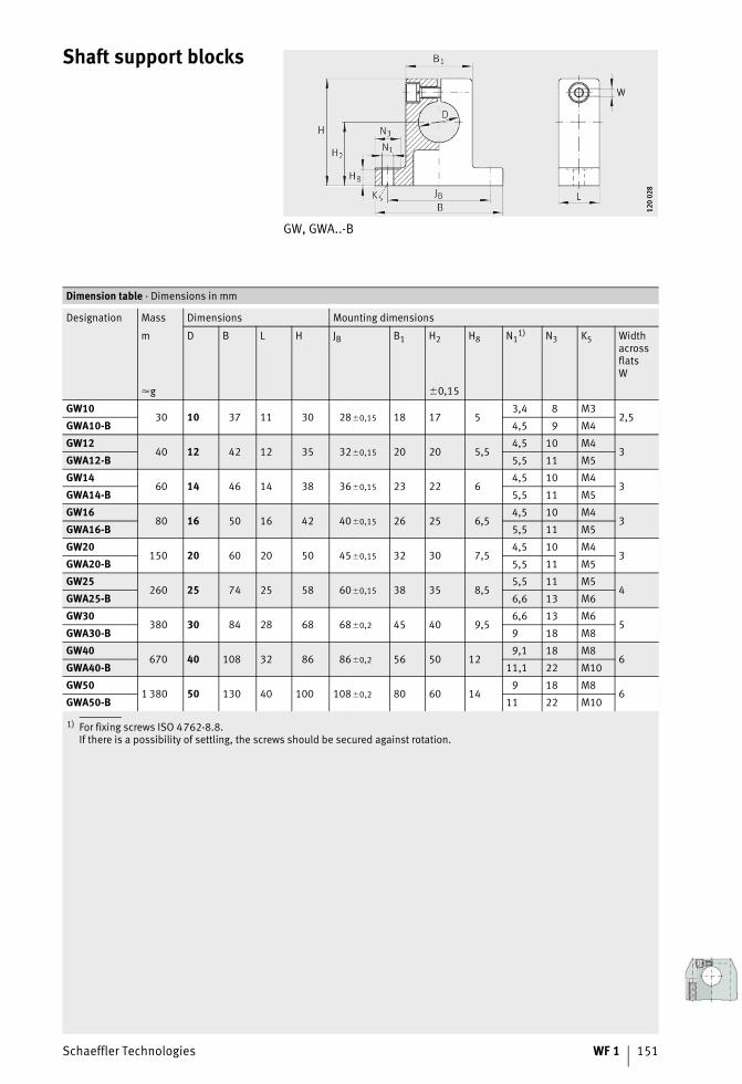
Schaeffler Technologies WF 1 151
Shaft support blocks
GW, GWA..-B
120
028
120
028
1) For fixing screws ISO 4762-8.8.If there is a possibility of settling, the screws should be secured against rotation.
Dimension table · Dimensions in mm
Designation Mass Dimensions Mounting dimensions
m D B L H JB B1 H2 H8 N11) N3 K5 Width
acrossflatsW
�g �0,15
GW1030 10 37 11 30 28�0,15 18 17 5
3,4 8 M32,5
GWA10-B 4,5 9 M4
GW1240 12 42 12 35 32�0,15 20 20 5,5
4,5 10 M43
GWA12-B 5,5 11 M5
GW1460 14 46 14 38 36�0,15 23 22 6
4,5 10 M43
GWA14-B 5,5 11 M5
GW1680 16 50 16 42 40�0,15 26 25 6,5
4,5 10 M43
GWA16-B 5,5 11 M5
GW20150 20 60 20 50 45�0,15 32 30 7,5
4,5 10 M43
GWA20-B 5,5 11 M5
GW25260 25 74 25 58 60�0,15 38 35 8,5
5,5 11 M54
GWA25-B 6,6 13 M6
GW30380 30 84 28 68 68�0,2 45 40 9,5
6,6 13 M65
GWA30-B 9 18 M8
GW40670 40 108 32 86 86�0,2 56 50 12
9,1 18 M86
GWA40-B 11,1 22 M10
GW501 380 50 130 40 100 108�0,2 80 60 14
9 18 M86
GWA50-B 11 22 M10
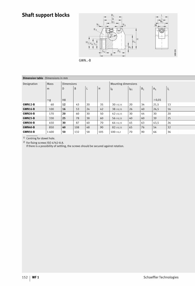
152 WF 1 Schaeffler Technologies
Shaft support blocks
GWN..-B
120
131
120
131
1) Centring for dowel hole.2) For fixing screws ISO 4762-8.8.
If there is a possibility of settling, the screws should be secured against rotation.
Dimension table · Dimensions in mm
Designation Mass Dimensions Mounting dimensions
m D B L H JB JB1 B1 A5 JL
�g H8 �0,01
GWN12-B 60 12 43 20 35 30�0,15 20 34 21,5 13
GWN16-B 100 16 53 24 42 38�0,15 26 40 26,5 16
GWN20-B 170 20 60 30 50 42�0,15 30 44 30 20
GWN25-B 330 25 78 38 60 56�0,15 40 60 39 25
GWN30-B 450 30 87 40 70 64�0,15 45 63 43,5 26
GWN40-B 850 40 108 48 90 82�0,15 65 76 54 32
GWN50-B 1 400 50 132 58 105 100�0,2 70 90 66 36
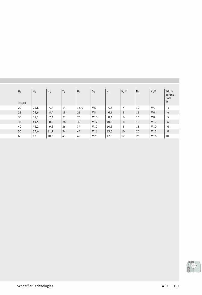
Schaeffler Technologies WF 1 153
H2 H4 H5 T5 H6 G2 N1 N41) N3 K5
2) WidthacrossflatsW�0,01
20 26,6 5,4 13 16,5 M6 5,3 4 10 M5 3
25 26,6 5,4 18 21 M8 6,6 5 11 M6 4
30 34,1 7,4 22 25 M10 8,4 6 15 M8 5
35 41,5 8,3 26 30 M12 10,5 8 18 M10 6
40 46,2 9,3 26 34 M12 10,5 8 18 M10 6
50 57,6 11,7 34 44 M16 13,5 10 20 M12 8
60 62 10,6 43 49 M20 17,5 12 26 M16 10
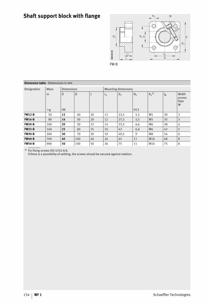
154 WF 1 Schaeffler Technologies
Shaft support block with flange
FW-B
0001
9C3D
0001
9C3D
1) For fixing screws ISO 4762-8.8.If there is a possibility of settling, the screws should be secured against rotation.
Dimension table · Dimensions in mm
Designation Mass Dimensions Mounting dimensions
m D B L L1 D1 N1 K51) JB Width
acrossflatsW
�g H8 H13
FW12-B 50 12 40 20 12 23,5 5,5 M5 30 3
FW16-B 80 16 50 20 12 27,5 5,5 M5 35 3
FW20-B 100 20 50 23 14 33,5 6,6 M6 38 4
FW25-B 160 25 60 25 16 42 6,6 M6 42 5
FW30-B 260 30 70 30 19 49,5 9 M8 54 6
FW40-B 700 40 100 40 26 65 11 M10 68 8
FW50-B 900 50 100 50 36 75 11 M10 75 8

Schaeffler Technologies WF 1 155
156 WF 1 Schaeffler Technologies
Addresses
Germany Schaeffler Technologies GmbH & Co. KGLinear Technology DivisionBerliner Straße 13466424 Homburg (Saar)Tel. +(49) 6841 701-0Fax +(49) 6841 [email protected]
Argentina Schaeffler Argentina S.r.l.Av. Alvarez Jonte 1938C1416EXR Buenos AiresTel. +(54) 11 40 16 15 00Fax +(54) 11 45 82 33 [email protected]
Australia Schaeffler Australia Pty Ltd.Level 1, Bldg. 8,Forest Central Business Park49 Frenchs Forest RoadFrenchs Forest, NSW 2086Tel. +(61) 2 8977 1000Fax +(61) 2 9452 [email protected]
Austria Schaeffler Austria GmbHFerdinand-Pölzl-Straße 22560 Berndorf-St. VeitTel. +(43) 2672 202-0Fax +(43) 2672 [email protected]
Belarus Schaeffler Technologies GmbH Co. KGRepräsentanz WeißrußlandOdoewskogo 117, office 317220015 MinskTel. +(375) 17 269 94 81Fax +(375) 17 269 94 [email protected]
Belgium Schaeffler Belgium S.P.R.L./B.V.B.A.Avenue du Commerce, 381420 Braine L’AlleudTel. +(32) 2 3 89 13 89Fax +(32) 2 3 89 13 [email protected]
Bosnia-Herzegovina
Schaeffler Hrvatska d.o.o.Ogrizovićeva 28b10000 ZagrebCroatiaTel. +(385) 1 37 01 943Fax +(385) 1 37 64 [email protected]
Brazil Schaeffler Brasil Ltda.Av. Independência, 3500-ABairro Éden 18087-101 Sorocaba, SPTel. +(55) 0800 11 10 29Fax +(55) 15 33 35 19 [email protected]
Bulgaria Schaeffler Bulgaria OODDondukov-Blvd. No 62Eing. A, 6. Etage, App. 101504 SofiaTel. +(359) 2 946 3900
+(359) 2 943 4008Fax +(359) 2 943 [email protected]
Schaeffler Technologies WF 1 157
Canada Schaeffler Canada Inc.2871 Plymouth DriveOakville, ON L6H 5S5Tel. +(1) 905 8 29 27 50
+(1) 800 263 4397 (Toll Free)Fax +(1) 905 8 29 25 [email protected]
China Schaeffler Trading (Shanghai) Co., Ltd.No. 1 Antuo Road (west side of Anhong Road), Anting, Jiading District201804 ShanghaiTel. +(86) 21 3957 6500Fax +(86) 21 3959 [email protected]
Croatia Schaeffler Hrvatska d.o.o.Ogrizovićeva 28b10000 ZagrebTel. +(385) 1 37 01 943Fax +(385) 1 37 64 [email protected]
CzechRepublic
Schaeffler CZ s.r.o.Průběžná 74a100 00 Praha 10Tel. +(420) 267 298 111Fax +(420) 267 298 [email protected]
Denmark Schaeffler Danmark ApSJens Baggesens Vej 90P8200 Aarhus NTel. +(45) 70 15 44 44Fax +(45) 70 15 22 [email protected]
Estonia Schaeffler TechnologiesRepräsentanz BaltikumDuntes iela 23a1005 RigaLatviaTel. +(371) 7 06 37 95Fax +(371) 7 06 37 [email protected]
Finland Schaeffler Finland OyLautamiehentie 302770 EspooTel. +(358) 207 36 6204Fax +(358) 207 36 [email protected]
France Schaeffler France SAS93 route de Bitche, BP 3018667506 Haguenau CedexTel. +(33) 3 88 63 40 40Fax +(33) 3 88 63 40 [email protected]
Great Britain Schaeffler (UK) Ltd.Forge Lane, MinworthSutton Coldfield B76 1APTel. +(44) 121 3 13 58 70Fax +(44) 121 3 13 00 [email protected]
Hungary Schaeffler Magyarország Ipari Kft.Rétköz utca 5.1118 BudapestTel. +(36) 1 4 81 30 50Fax +(36) 1 4 81 30 [email protected]
Italy Schaeffler Italia S.r.l.Via Dr. Georg Schaeffler, 728015 MomoTel. +(39) 0321 929 211Fax +(39) 0321 929 [email protected]
Japan Schaeffler Japan Co., Ltd.New Stage Yokohama 1-1-32Shinurashima-cho222-0031 YokohamaTel. +(81) 45 274 8211Fax +(81) 45 274 [email protected]
Korea Schaeffler Korea Corporation14F, Kyobo life insurance Bldg.Seoul, 110-714Tel. +(82) 2 311 3440Fax +(82) [email protected]
Latvia Schaeffler TechnologiesRepräsentanz BaltikumDuntes iela 23a1005 RigaTel. +(371) 7 06 37 95Fax +(371) 7 06 37 [email protected]
Lithuania Schaeffler TechnologiesRepräsentanz BaltikumDuntes iela 23a1005 RigaLatviaTel. +(371) 7 06 37 95Fax +(371) 7 06 37 [email protected]
158 WF 1 Schaeffler Technologies
Addresses
Mexico INA Mexico, S.A. de C.V.Rodamientos FAG, S.A. de C.V.Henry Ford #141Col. BondojitoDeleg. Gustavo A. Madero07850 Mexico D.F.Tel. +(52) 55 5062 6085Fax +(52) 55 5739 [email protected]
Netherlands Schaeffler Nederland B.V.Gildeweg 313771 NB BarneveldTel. +(31) 342 40 30 00Fax +(31) 342 40 32 [email protected]
New Zealand Schaeffler New Zealand(Unit R, Cain Commercial Centre)20 Cain Road1135 PenroseTel. +(64) 9 583 1280
+(64) 021 324 247 (Call out fee applies)
Fax +(64) 9 583 [email protected]
Norway Schaeffler Norge ASGrenseveien 107B0663 OsloTel. +(47) 23 24 93 30Fax +(47) 23 24 93 [email protected]
Poland Schaeffler Polska Sp. z.o.o.Budynek Eul. Szyszkowa 35/3702-285 WarszawaTel. +(48) 22 8 78 41 20Fax +(48) 22 8 78 41 [email protected]
Portugal INA Rolamentos Lda.Arrábida Lake TowersRua Daciano Baptista Marques Torre C, 181, 2º piso4400-617 Vila Nova de GaiaTel. +(351) 22 5 32 08 00Fax +(351) 22 5 32 08 [email protected]
Romania S.C. Schaeffler Romania S.R.L.Aleea Schaeffler Nr. 3507055 Cristian/BrasovTel. +(40) 268 505000Fax +(40) 268 [email protected]
Russia Schaeffler Rußland GmbHPiskarevsky prospect, 2, build.3, letter ABC „Benua“, office 207195027 St. PetersburgTel. +(7) 812 633 3644Fax +(7) 812 633 [email protected]
Schaeffler RußlandLeningradsky Prospekt 47, Bau 3Business-Center Avion125167 MoscowTel. +(7) 495 73776-60Fax +(7) 495 [email protected]
Serbia Schaeffler TechnologiesRepräsentanz SerbienBranka Krsmanovica 1211118 BeogradTel. +(381) 11 308 87 82Fax +(381) 11 308 87 [email protected]
Singapore Schaeffler (Singapore) Pte. Ltd.151 Lorong Chuan, #06-01New Tech Park, Lobby A556741 SingaporeTel. +(65) 6540 8600Fax +(65) 6540 [email protected]
SlovakRepublic
Schaeffler Slovensko, spol. s.r.o.Ulica Dr. G. Schaefflera 102401 Kysucké Nové MestoTel. +(421) 41 4 20 59 11Fax +(421) 41 4 20 59 [email protected]
Slovenia Schaeffler Slovenija d.o.o.Glavni trg 17/b2000 MariborTel. +(386) 2 22 82 070Fax +(386) 2 22 82 [email protected]
Schaeffler Technologies WF 1 159
South Africa Schaeffler South Africa (Pty.) Ltd.1 End Street Ext. Corner Heidelberg Road2000 JohannesburgTel. +(27) 11 225 3000Fax +(27) 11 334 [email protected]
Spain Schaeffler Iberia, s.l.u.C/ Foment, 2Polígono Ind. Pont Reixat08960 Sant Just DesvernTel. +(34) 93 4 80 34 10Fax +(34) 93 3 72 92 [email protected]
Sweden Schaeffler Sverige ABCharles gata 10195 61 ArlandastadTel. +(46) 8 59 51 09 00Fax +(46) 8 59 51 09 [email protected]
Switzerland HYDREL GmbHBadstraße 148590 RomanshornTel. +(41) 71 4 66 66 66Fax +(41) 71 4 66 63 [email protected]
Turkey Schaeffler Rulmanlari Ticaret Limited SirketiAydin Sokak Dagli Apt. 4/41. Levent34340 IstanbulTel. +(90) 212 2 79 27 41
+(90) 212 280 77 98Fax +(90) 212 281 66 45
+(90) 212 280 94 [email protected]
Ukraine Schaeffler TechnologiesRepresentative Office UkraineJilyanskayastr. 75, 5-er StockBusiness Center «Eurasia»01032 KiewTel. +(380) 44 520 13 80Fax +(380) 44 520 13 [email protected]
USA Schaeffler Group USA Inc.308 Springhill Farm RoadCorporate OfficesFort Mill, SC 29715Tel. +(1) 803 548 8500Fax +(1) 803 548 [email protected]

160 WF 1 Schaeffler Technologies
Notes

Schaeffer Technologies GmbH & Co. KG
Linear Technology Division Berliner Straße 134 66424 Homburg/Saar (Germany) Internet www.ina.com E-mail [email protected]
In Germany: Phone 0180 5003872 Fax 0180 5003873
From other countries: Phone +49 6841 701-0 Fax +49 6841 701-2625M
ATN
R 03
4139
060
-000
0 / W
F 1
/ 01
/ GB
-D /
2014
028
/ Pri
nted
in G
erm
any
by m
ohn