Embed Size (px)
Citation preview

Shaft Generators for Low Speed Main Engines


Contents
Preface ........................................................................................................5
Introduction .................................................................................................5
PTO/GCR (power take off/gear constant ratio) ..............................................7
PTO/RCF (power take off/RENK constant frequency) .................................. 10
PTO/CFE (Power Take Off/Constant Frequency Electrical) ........................... 11
Characteristics of electric power from shaft generators ............................... 13
Engine mounted front-end installation (BW I) ............................................... 15
Tank top mounted front end PTO installation (BW II) .................................... 16
RENK installation (BW III) mounted on engine side ...................................... 18
Aft-end installation (BW IV/GCR) mounted on tank top ............................... 19
Aft-end installation (SMG/CFE) mounted on propeller shaft ......................... 21
Front-end PTO installation mounted on engine (DMG/CFE) ......................... 22
Layout for engine driving a fixed pitch propeller ........................................... 25
Layout for engine prepared for driving a fixed pitch propeller and
shaft generator ........................................................................................... 26
Special layout for engine with fixed pitch propeller and shaft generator ........ 27
Engine layout with controllable pitch propeller and shaft generator .............. 28
Layout for engine driving a fixed pitch propeller and shaft generator/motor . 28
Engines with small PTO applications ........................................................... 30
Engines with large PTO applications ........................................................... 30
PTO advantages ........................................................................................ 32
PTO disadvantages .................................................................................... 32
PTO used with shuttle tankers .................................................................... 35
Auxiliary electric propulsion system ............................................................. 37
Auxiliary hydraulic propulsion system .......................................................... 38
RENK propeller shaft clutch ........................................................................ 39
Power turbine generator ............................................................................. 41
MHI hybrid turbocharger ............................................................................ 41
MHI electro-assist turbocharger .................................................................. 42
The combined RENK shaft generator and waste heat recovery system ........ 43
Introduction ............................................................................................... 44
Summary ................................................................................................... 44
References................................................................................................. 46


Shaft generators for low speed main engines 5
Preface
The purpose with this paper is to
provide detailed information about
different categories of shaft gen-
erators driven by a MAN B&W low
speed marine engine used for ship
propulsion.
The paper describes different types
of marine shaft generators and their
configurations, with the physical
connecting interfaces to the main
engine or to the intermediate propel-
ler shaft. It will provide a description
of relevant aspects and can be used
for reference.
Introduction
After the first MC engine was intro-
duced in 1982, MAN Diesel & Turbo
started investigating the possibility for
using a low speed main engine driven
shaft generator for generating the elec-
tric power on ships as an alternative to
the four-stroke gensets.
This was motivated by the rising fuel
prices and the fact that, at that time,
most four-stroke gensets could only
operate on the more expensive marine
diesel oil. The low speed main engine
was able to operate on the cheaper
heavy fuel oil, and the marine industry
therefore looked into the possibility for
using a main engine driven shaft genera-
tor alternative. Various reliable shaft gen-
erators were developed, and the electric
power generated from shaft generators,
combined with the prolonged length be-
tween overhaul for the shaft generator
and low speed main engine compared
to the four-stroke genset, rapidly be-
came popular among operators.
However, references have shown that
a number of shipowners and opera-
tors still consider a shaft generator as
an attractive investment for ships like
container vessels, product tankers and
shuttle tankers. This is probably as-
cribed to the fact that shaft generators
and low speed main engines are con-
sidered to be highly reliable and offers
savings from prolonged time between
overhauls compared to a four-stroke
genset solution. This means that by
selecting the right shaft generator and
main engine layout, operating hours can
be saved on the four-stroke gensets
because they can be shut down during
voyage.
Supported by examples of typical and
special shaft generator installations,
this paper describes the most com-
monly used systems and the connect-
ing interface to the low speed main en-
gine or propeller shaft.
In the following, the term “shaft genera-
tor” is used for any arrangement where
a power take off from the main engine
prime mover or its shaft line is used to
drive an alternator for the purpose of
generating electric power.
Shaft generators for low speed main engines

Shaft generators for low speed main engines6
MAN Diesel & Turbo distinguishes be-
tween three main categories of shaft
generators:
PTO/GCR (power take-off/gear con-
stant ratio) consists of flexible coupling,
step-up gear and alternator.
PTO/RCF (power take-off/RENK con-
stant frequency) consists of flexible cou-
pling, step-up gear, torsion rigid toothed
coupling, RCF gear and alternator.
PTO/CFE (power take-off/constant
frequency electrical) consists of slow
running alternator with electrical control
equipment.
PTO/RCF and PTO/CFE shaft genera-
tors incorporate various frequency con-
trol systems that allow them to generate
electric power with constant electrical
frequency at varying engine speed.
The designations BW I, BW II, BW III
and BW IV distinguish between various
physical configurations.
In MAN Diesel & Turbo terms, a 700 kW
(60 Hz) GCR shaft generator type in-
tended for installation with an S50ME-
C engine is designated: BW III S50ME-
C/GCR 700 - 60.
Descriptions of PTO/GCR, PTO/RCF
and PTO/CFE shaft generator types
and the various configurations possibili-
ties appear from the principles sketched
in Fig. 1 and represent the most typical
shaft generator layouts, based on infor-
mation from the suppliers.
Fig. 1: Alternative types and layouts of shaft generator systems.
Definitions and designations of shaft generators
Alternative types and layouts of shaft generators Design Seating Total efficiency (%)
PT
O/R
CF
1a 1b BW I/RCFOn engine
(vertical generator)88-91
2a 2b BW II/RCF On tank top 88-91
3a 3b BW III/RCF On engine 88-91
4a 4b BW IV/RCF On tank top 88-91
PT
O/C
FE 5a 5b DMG/CFE On engine 84-88
6a 6b SMG/CFE On tank top 84-88
PT
O/G
CR
PT
O/C
FE 7
BW I/GCR
BW-I/CFE
On engine
(vertical generator)
92
81-85
8BW II/GCR
BW-II/CFEOn tank top
92
81-85
9BW III/GCR
BW-III/CFEOn engine
92
81-85
10BW IV/GCR
BW-IV/CFEOn tank top
92
81-85

Shaft generators for low speed main engines 7
PTO/GCR (power take off/gear con-stant ratio)Layout for operating at constant propeller
speed
The PTO/GCR system is the most
simple and cheapest of the shaft gen-
erators, and it comprises a standard
synchronous alternator and a simple
step-up gear. Its simplicity is attractive,
and many shipowners use it to gener-
ate all the electric power at constant
electrical frequency during the voyage.
Since the frequency produced by the
alternator is proportional to the en-
gine speed, the operation of this type
of shaft generator normally takes place
at constant propeller speed. The GCR
shaft generator system is therefore
normally utilised in connection with a
controllable pitch propeller, with which
constant propeller speed and relatively
constant frequency are available over a
wide engine power range.
The small engine speed and frequen-
cy variations that occur even for the
main engine running at constant speed
mode means that the GCR system is
not normally utilised for long term par-
allel running with the gensets. Conse-
quently, the electric power generation
from the GCR generator type only takes
place during the voyage supplying all
the electric power while the gensets are
out of operation.
Layout for operating at combinatory curve
At near zero propeller pitch, the con-
stant speed CP-propeller sees a sig-
nificant drop in propeller efficiency.
This means that ships with a typical
low speed profile, i.e. ships trading in
coastal areas or rivers, can benefit from
operating the CP-propeller at a lower
propeller speed at low engine loads.
To be able to benefit from an improved
CP-propeller efficiency at a lower pro-
peller speed, the GCR shaft generator
is disconnected and the gensets are
employed.
However, to avoid disconnecting the
shaft generator at reduced propeller-
and ship speeds, it is possible to install
a more expensive two-step gear solu-
tion that can be utilised at the alternative
power range found at lower propeller
speeds to maintain the right electrical
frequency from the alternator.
The lower propulsion power for differ-
ent CP-propeller speed and pitch diam-
eter ratio is illustrated in the power and
propeller speed diagram in Fig. 3.
Fig. 2: Shaft mounted BW IV/GCR system
Categories of shaft generators
Shaft generators for low speed main engines8
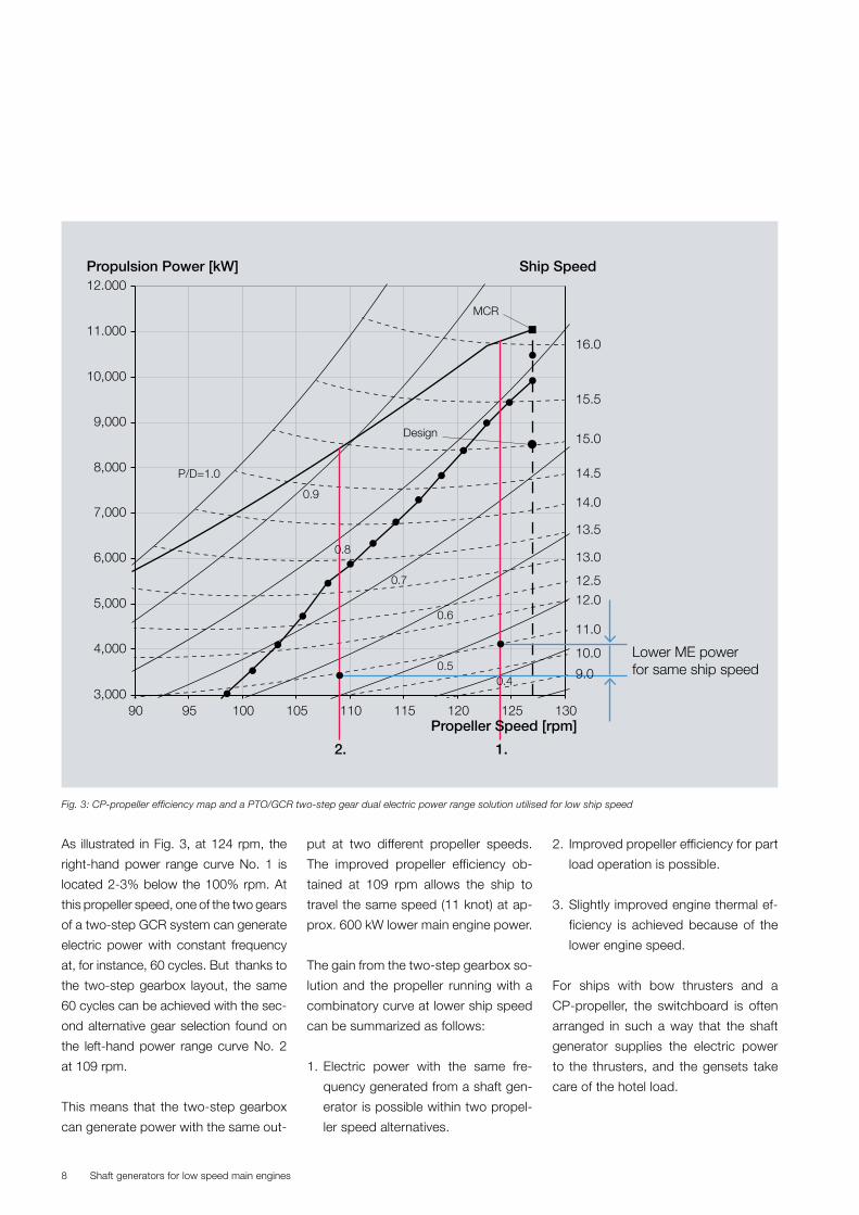
As illustrated in Fig. 3, at 124 rpm, the
right-hand power range curve No. 1 is
located 2-3% below the 100% rpm. At
this propeller speed, one of the two gears
of a two-step GCR system can generate
electric power with constant frequency
at, for instance, 60 cycles. But thanks to
the two-step gearbox layout, the same
60 cycles can be achieved with the sec-
ond alternative gear selection found on
the left-hand power range curve No. 2
at 109 rpm.
This means that the two-step gearbox
can generate power with the same out-
put at two different propeller speeds.
The improved propeller efficiency ob-
tained at 109 rpm allows the ship to
travel the same speed (11 knot) at ap-
prox. 600 kW lower main engine power.
The gain from the two-step gearbox so-
lution and the propeller running with a
combinatory curve at lower ship speed
can be summarized as follows:
1. Electric power with the same fre-
quency generated from a shaft gen-
erator is possible within two propel-
ler speed alternatives.
2. Improved propeller efficiency for part
load operation is possible.
3. Slightly improved engine thermal ef-
ficiency is achieved because of the
lower engine speed.
For ships with bow thrusters and a
CP-propeller, the switchboard is often
arranged in such a way that the shaft
generator supplies the electric power
to the thrusters, and the gensets take
care of the hotel load.
11.000
10,000
9,000
8,000
7,000
6,000
5,000
4,000
3,00090 95
P/D=1.0
0.9
Design
Lower ME powerfor same ship speed
MCR
0.8
0.7
0.6
0.50.4
100 105 110Propeller Speed [rpm]
Propulsion Power [kW] Ship Speed
2. 1.
115 120 125 130
16.0
15.5
15.0
14.5
14.0
13.5
13.0
12.5
12.0
11.0
10.0
12.000
9.0
Fig. 3: CP-propeller efficiency map and a PTO/GCR two-step gear dual electric power range solution utilised for low ship speed

Shaft generators for low speed main engines 9
The investment in a GCR shaft genera-
tor type is much smaller than the more
sophisticated PTO/RCF or other PTO/
CFE systems which are ready for paral-
lel running with gensets.
The total efficiency of a PTO/GCR unit
is around 92%, corresponding to a 2
and 6% loss from gear and alternator.
The shaft generator layout operation
range should be based on the expect-
ed ship operation profile, in order to
ensure the longest possible operation
time for the shaft generator.
Layout for operating with a fixed pitch pro-
peller
Due to the nature of the fixed pitch
propeller, the speed of the propeller
and engine, vary with the required ship
speed and the resistance acting on the
ship. Consequently, the electric power
generated from a PTO/GCR system
would have a variable frequency.
Most electrical equipment can operate
with a frequency at between 50 and 60
Hz without problems. This means that
the PTO/GCR system can be utilised in
the 52% to 90% engine power range,
corresponding to an engine speed
range of 80% and 97%. This indicates
that the PTO/GCR shaft generator type
can be used to supply electric power
for that equipment most of the time,
see also page 13.
When utilising the cheap PTO/GCR sy-
atem in combination with a fixed pitch
propeller speed, the limited part of
sensitive electrical equipment that re-
quires fixed frequency then have to be
powered by smaller adapted frequency
converters close to the few critical con-
sumers that rely on constant frequency.
Summary
Several manufacturers are able to sup-
ply different kinds of PTO/GCR systems.
Fig. 4: Small adapted rotating frequency converter

Shaft generators for low speed main engines10
PTO/RCF (power take off/RENK con-stant frequency)
The PTO/RCF system produces elec-
tricity with a constant electrical fre-
quency over a wide propeller speed
range, and the shaft generator type can
be utilised in combination with a fixed
pitch propeller and continuous opera-
tion in parallel with gensets.
The PTO/RCF incorporates the RCF
speed controlled planetary gearbox
ensuring a constant speed for the al-
ternator within a certain propeller speed
range. This mechanical-hydraulic RCF
gear unit has been developed by RENK
and is only available from this supplier.
Based on the detected output speed
from the crankshaft gear, the RCF gear
transmission can serve a constant
speed to the alternator over an engine
speed range of 35%. It consists of an
epicyclic gear with a hydrostatic super-
position drive.
The hydrostatic motor is controlled by
an electronic control unit and is driven
by the built-on hydrostatic pump.
The hydrostatic system drives the an-
nulus of the epicyclic gear in either
direction of rotation and continuously
varies the gear ratio according to the
engine speed.
In the standard PTO/RCF layout, the
output speed range of the gearbox is
set between 70% to 105% of the en-
gine’s specified MCR speed, but this
could be selected otherwise.
The speed range from 70% to 105%
equals an engine power of between
34% to 105%, see page 13.
PTO/RCF–BW IIIRENK
42-98MC
To panel
Hydrostaticcontrol
Hydrostaticmotor
Toothed coupling
Alternator
Operator control panel(in switchboard)
Hydrostatic pump
Multi-disc clutch
Toothed coupling
ControllerTerminal
Elastic damping coupling
Toothed coupling
Fig. 6: The engine side front end mounted installation BW III RENK PTO/RCF solution

Shaft generators for low speed main engines 11
with fixed pitch propellers and continu-
ous operation in parallel with gensets.
The most commonly used PTO/CFE is
as a slow-running alternator type oper-
ating at the same speed as the propel-
ler shaft. Alternative and faster step-up
gear systems with a low-cost synchro-
nous alternator are possible, but only a
limited number of step-up-gear-based
PTO/CFE systems have been intro-
duced. The PTO BW III/GCR-CFE step-
up solution from RENK is shown on
page 19.
The PTO/CFE slow-running alternator
is available as an engine-mounted front
end DMG/CFE solution, or installed as
a tank-top-mounted aft end SMG/CFE
solution with the rotor integrated on the
intermediate propeller shaft.
More poles are necessary for a low
speed operated synchronous alterna-
tor. This means that the alternator type
becomes bigger than for the step-up-
gear based alternative. The slow-running
alternator type does not need any kind
of flexible coupling, necessary for the
faster-running step-up gear shaft gen-
erator types.
Both the DMG/CFE and the SMG/
CFE are able to operate in parallel with
the gensets and serve full rated elec-
tric power output when the speed of
the main engine is between 75% and
105%, which equals an engine power
range of 40% to 105%.
The CFE system also has the capac-
ity for a reduced electric output that is
proportional to the engine speed of be-
tween 40% to 75% of the SMCR speed,
The PTO/RCF system can serve elec-
tric power to all power consumers on
the voyage.
During parallel running with gensets, the
internal electronic control box system,
included with the RCF unit, ensures that
the control signals to the main electric
switchboard are identical to those of the
gensets. This allows the PTO/RCF to
operate alone or in parallel with gensets
throughout a 35% speed range.
Internal control circuits and interlocking
functions between the epicyclic gear
and the electronic control box provide
automatic control of the functions nec-
essary for the satisfactory operation
and protection of the RCF gear. By the
extent of deviation or severity from the
permissible values, caused by incidents
or failure, a warning or alarm will be
shown on a display.
Summary
PTO/RCF is suitable for ships with a
fixed pitch propeller.
During operation, the multi-disc clutch
integrated into the RCF gearbox input
shaft permits disengaging of the epicy-
clic RCF gear and alternator from the
step-up gear driving by the main engine.
Depending on the actual engine speed
relative to the maximum speed layout of
the RCF unit, the total efficiency of the
RCF shaft generator system varies be-
tween 88% and 91%.
PTO/CFE (Power Take Off/Constant Frequency Electrical)
The PTO/CFE generates electric power
with constant electrical frequency over
a wide engine speed range. The shaft
generator can be used in combination
Fig. 7: The hydraulic speed controlled planetary gear box supplies constant speed for the alternator.

Shaft generators for low speed main engines12
which equals an engine power range of
6.4% and 40%, see page 13.
A traditional PTO/CFE shaft generator
is installed with a thyristor converter
and synchronous condenser.
The alternator generates a three-phase
alternating current with a varying fre-
quency that corresponds to the pro-
peller speed. This is then rectified and
conducted to the thyristor converter
system in the engine room, which pro-
duces alternating current with constant
frequency. The synchronous condens-
er is necessary because the DC inter-
mediate link used by the thyrister con-
verter system has the effect that there
will be no reactive power served to the
main switchboard. A synchronous con-
denser is therefore necessary to gener-
ate the reactive power needed.
A novel marine shaft-driven genera-
tor system with two PWM-pulse width
modulated converters has been intro-
duced. With this system, one of the
PWM converters is used to convert
the varying current into the DC energy.
Afterwards, the other PWM converter
converts the DC energy into AC energy
with the fixed frequency and voltage.
Thanks to the space vector control
used with this converter system, the
generator can maintain a constant volt-
age and frequency. The PWM pulse
width modulated converter system is
able to supply effective power and re-
active power to load on ships without a
synchronous condenser and, thereby,
simplifies the installation and later on
maintenance processes.
The traditional thyrister converter run-
ning with a synchronous condenser is
illustrated by the control principle for a
DMG/CFE unit, Fig. 8.
However, the tank-top-mounted aft end
SMG/CFE solution with integrated ro-
tor on the intermediate propeller shaft
is much more frequently used than the
DMG/CFE, because it is not subjected
to any limitations from the installation on
the main engine and the limited space
between the bulkhead and PTO.
Summary
The CFE shaft generator system is suit-
able for ships with fixed pitch propeller.
The total efficiency of the slow running
CFE types varies from 89% to 91%.
Fig. 8: PTO DMG/CFE engine-mounted front end design
Mains, constant frequency
Excitationconverter
Synchronouscondenser
SmoothingreactorStatic
converterDMGDiesel engine
Shaft generators for low speed main engines 13
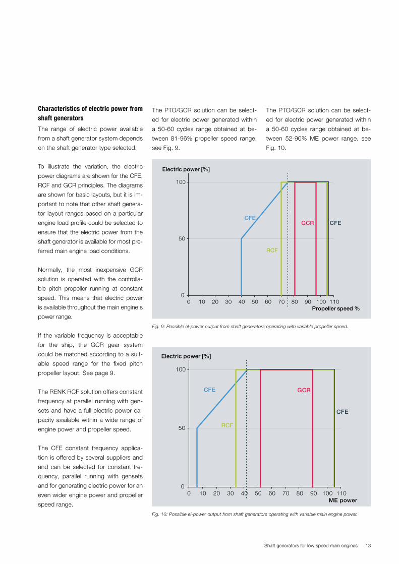
Fig. 9: Possible el-power output from shaft generators operating with variable propeller speed.
Fig. 10: Possible el-power output from shaft generators operating with variable main engine power.
0
50
100
0 10 20 30 40 50 60 70 80 90 100 110
Electric power [%]
Propeller speed %
CFEGCR CFE
RCF
0
50
100
0 10 20 30 40 50 60 70 80 90 100 110
Electric power [%]
ME power
CFE GCR
RCF
CFE
Characteristics of electric power from shaft generators
The range of electric power available
from a shaft generator system depends
on the shaft generator type selected.
To illustrate the variation, the electric
power diagrams are shown for the CFE,
RCF and GCR principles. The diagrams
are shown for basic layouts, but it is im-
portant to note that other shaft genera-
tor layout ranges based on a particular
engine load profile could be selected to
ensure that the electric power from the
shaft generator is available for most pre-
ferred main engine load conditions.
Normally, the most inexpensive GCR
solution is operated with the controlla-
ble pitch propeller running at constant
speed. This means that electric power
is available throughout the main engine‘s
power range.
If the variable frequency is acceptable
for the ship, the GCR gear system
could be matched according to a suit-
able speed range for the fixed pitch
propeller layout, See page 9.
The RENK RCF solution offers constant
frequency at parallel running with gen-
sets and have a full electric power ca-
pacity available within a wide range of
engine power and propeller speed.
The CFE constant frequency applica-
tion is offered by several suppliers and
and can be selected for constant fre-
quency, parallel running with gensets
and for generating electric power for an
even wider engine power and propeller
speed range.
The PTO/GCR solution can be select-
ed for electric power generated within
a 50-60 cycles range obtained at be-
tween 81-96% propeller speed range,
see Fig. 9.
The PTO/GCR solution can be select-
ed for electric power generated within
a 50-60 cycles range obtained at be-
tween 52-90% ME power range, see
Fig. 10.

Shaft generators for low speed main engines14
Engine power and speed ranges available in PTO operation mode
PTO layout PTO used with Propeller speed ME power Max. electric power output Frequency
% % % Cycles
CFE 40 6.4 50 60
CFE 75 42.2 100 60
CFE 105 105 100 60
RCF 70 34.3 100 60
RCF 105 105 100 60
GCR Variable frequency 80.6 52.1 100 50
GCR Variable frequency 96.5 90 100 60
Fig. 11: Electric power output from shaft generator based on PTO layouts given by Fig. 9 and Fig. 10.

Shaft generators for low speed main engines 15
Encoder system used with electron-
ically controlled engines
The electronically controlled low speed
engine system relies on the robust en-
gine encoder system developed by
MAN Diesel & Turbo. For most applica-
tions, this encoder system is mounted
on the foremost shielding system con-
nected to the front end of the crankshaft
flange, where it continuously sends the
exact position of the crankshaft to the
ME control system.
Shop testing of electronically con-
trolled engines prepared for a front-end
mounted PTO normally takes place with
the standard encoder system mounted
on the front-end shielding system with-
out the PTO unit installed.
Afterwards, when the engine has fin-
ished the shop test running, the stand-
ard engine encoder system is reused
and mounted on the foremost PTO
shielding. Therefore, the PTO maker
must study the encoder system in ad-
vance and prepare a suitable and sta-
ble interfacing for the encoder housing
and pickup, ready for installation at the
shipyard at PTO assembly.
Engine mounted front-end installation (BW I)
The BW I system, available for GCR
and RCF shaft generators from RENK,
comprises a bevel gear and a step-up
gear bolted directly to the front-end en-
gine structure. The bevel gear allows
the alternator a vertical position on
top of the gear unit. This compact de-
sign gear system is only available from
RENK and is delivered with a combined
flexible toothed coupling.
Fig. 13: BW I S70/RCF 850-60 (RENK)
Physical shaft generator types and mounting configuration

Shaft generators for low speed main engines16
Flexible toothed coupling and
lubrication
The flexible coupling used with RENK
shaft generators, supplied by Geisling-
er, is bolted in place between the crank-
shaft free end and the step-up gear. In
this way, transmission of torsion and
longitudinal excitations from the crank-
shaft to the step-up gear are avoided.
The integrated flexible elements con-
sist of packages of steel springs. The
damping of torsional excitations is
achieved with steel springs squeez-
ing oil from one chamber to the other,
when they are deflecting during opera-
tion. Together with the damping func-
tion, the oil provides the necessary
lubrication and cooling to the coupling
bolted to the crankshaft free end.
The toothed coupling allows a simple
separation of the step-up gear and
crankshaft if special events occur and
require full access to the limited space
behind the PTO gear unit.
If the torsion characteristics of the shaft
system require additional inertia mass
fitted to the crankshaft flange free end,
it is possible to mount a tuning wheel
or a torsional vibrations damper in the
space between the shaft generator
gear box housing and engine structure.
The bearings installed in the BW I gear-
box structure support the mass of the
gear wheels, the Geislinger coupling,
and any additional mass bolted to the
crankshaft flange in order to adjust the
torsional vibration damper according
to the final vibration analysis.
If a Geislinger damper needs to be
mounted on the engine crankshaft
flange, both the damper and flexible
toothed coupling will be lubricated and
cooled by the main engine lubricating
system through the hollow step-up
gear shaft.
The engine-mounted step-up gear re-
lies on the main engine lubricating oil
system, and with a lubricating oil load
level of 8, according to the standardised
FZG Gear Test (DIN 51354), the capac-
ity of the main engine’s lubricating oil
system must be increased accordingly.
The hydrostatic drive controlling the
RCF gear provides a constant shaft
speed input to the alternator and re-
quire a 5µm filtration of the oil of its own.
Normally integrated between the step-
up gearbox and alternator, the multi-
disc clutch is used for engaging or dis-
engaging of components during main
engine operation.
On an RCF gear unit, the multi-disc
clutch is mounted before the RCF gear
input shaft and will be lubricated by a
step-up gear driven pump.
The electrically driven PTO-integrated
lubricating oil stand-by pump supple-
ments the step-up gear driven pump
during engine start and if the gear driv-
en pump malfunctions.
PTO preparations (BW I)
Approved interface and connection for
ME engine encoder system.
Engine preparations (BW I)
� Weld on blocks machined for align-
ment of the gear unit
� Monitoring system for axial excitations
� Flange for lubricating oil
� Return flange welded on to bedplate
� To ensure a stiff connection between
the main engine parts and the PTO,
adapted machined steel washers are
placed between the PTO crankshaft
gearbox and the A-frame so as to
compensate for the approx. 3 mm
difference in length between the en-
gine structure parts.
Engine room preparations (BW I)
� External wiring of the control system
� Cooling water supply for built-on oil
cooler
� Wiring between alternator, switch-
board and to the control system
� Electric power supply for built-on
electric lubricating oil stand-by pump.
For the PTO BW I/RCF type it is recom-
mended that the shipyard install an ex-
ternal lubricating oil filling system with a
dosage tank having a specified volume
for one RCF gearbox oil change.
Tank top mounted front end PTO in-stallation (BW II)
The BW II works as a freestanding gen-
erator solution in front of the engine.
A rubber-type flexible damping cou-
pling needs to be installed between
the engine and PTO step-up gearbox
outside the engine. The engine drives
the shaft generator via an intermediate
shaft, bolted to the engine crankshaft
flange and passes through the engine
front-end cover made in two halves
with an oil sealing arrangement.

Shaft generators for low speed main engines 17
The installation length of the PTO BW II
in front of the engine normally exceeds
the built-in length compared with other
types of PTO arrangements. But, de-
pending on the space available, there
are some possibilities for limiting the
length. Fig. 15 shows a concept where
the alternator is placed horizontally
between the step-up gearbox and the
front end of the engine, thus utilising
the space anyway taken up by the flex-
ible coupling.
A small support bearing is often in-
stalled between the front end of the en-
gine and the flexible coupling. Whether
such a support bearing is required
can be determined from MAN Diesel &
Turbo specification of the permissible
shear force and bending moment on
the front end of the crankshaft.
The PTO BW II has its own lubricating
oil system, and an integrated electrical-
ly driven lubricating oil stand-by pump
supplements the gear driven pump
during engine start-up and in the event
of malfunctioning of the gear driven
pump.
The bevel gear solution in the step-up
gearbox enables a vertical installation
of the alternator, Fig. 16.
Various gearbox manufacturers are
able to supply the PTO BW II/GCR sys-
tems, but only RENK is able to supply
the PTO BW II/RCF system with possi-
bility for constant frequency operation.
Fig. 14: Tank top mounted front end PTO BW II installation in front of the engine.
Fig. 15: PTO BW II with alternator mounted between gearbox and engine structure
Fig. 16: PTO BW II installation with alternator mounted vertically above gearbox
AlternatorTorsionallyrigid coupling
Step-upgear
Main engineside
Supportbearing
Flexible coupling
Flexiblecoupling
Alternator
Step-upgear

Shaft generators for low speed main engines18
Engine preparations (BW II)
� Replacement for the standard ME
engine encoder system on the en-
gine’s aft end turning wheel
� Intermediate shaft between the en-
gine and the flexible coupling
� Engine front-end cover with oil seal-
ing arrangement
� Axial excitations monitoring system.
Engine room preparations (BW II)
� Tank-top seating for bearings and
gearbox
� Cooling water supply for the built-on
oil cooler
� Electric power supply to the built-on
lubricating oil stand-by pump
� Wiring between alternator, switch-
board and control system
� For the PTO BW II/RCF solution,
the shipyard is recommended to in-
stall an external lubricating oil filling
system with a dosage tank having a
specified volume for one RCF gear-
box oil change.
RENK installation (BW III) mounted on engine side
The PTO BW III/GCR/RCF step-up gear
system is directly bolted to the front-
end engine structure, and the frame
supporting the alternator is placed hori-
zontally alongside on engine supported
brackets.
For the PTO BW III/RCF solution, the
RCF gear unit supplying constant
speed for the alternator is mounted on
the frame before the alternator, see Fig.
18.
The RENK gearbox is available for 40
bore engines and larger for standard
sizes of alternators at 700, 1200, 1800
and 2600 kW, but others are available
on request.
The flexible toothed coupling used by
the BW I and BW III RENK solutions,
supplied by Geislinger, is included in
the delivery from RENK.
The investment cost of the PTO BW
III system is typical higher than for the
other gear-based shaft generators. It
is bolted to the engine structure, and
there is no need for additional founda-
tion in the engine room. It is therefore
considered to be a compact and easy-
to-install PTO solution. The RCF gear-
box unit supplies the right input speed
to the alternator and a space requiring
frequency converter system in the en-
gine room is not necessary.
Fig. 17: RENK PTO BW III/GCR design
Fig. 18: RENK PTO BW III/RCF design
Alternator
Bedframe
Toothed coupling Multi-disc clutch
CombinedGeislingerand toothedcouplin
Crankshaftgear
Brackets
Operatorcontrolpanel
Alternator
Controller
Bedframe
RCF unitincl. multidisc clutch
Toothed coupling
Brackets
CombinedGeislingerand toothedcoupling
Crankshaft gear
Shaft generators for low speed main engines 19
Static frequency converter system
Synchronouscondenser Distribution cubicle
Converter cubicle
Excitation cubicle
Control cubicle
Toswitchboard
Alternator
Bedframe
Toothed coupling Multi-disc clutch
Combined Geislingerand toothed couplin
Crankshaft gear
Brackets
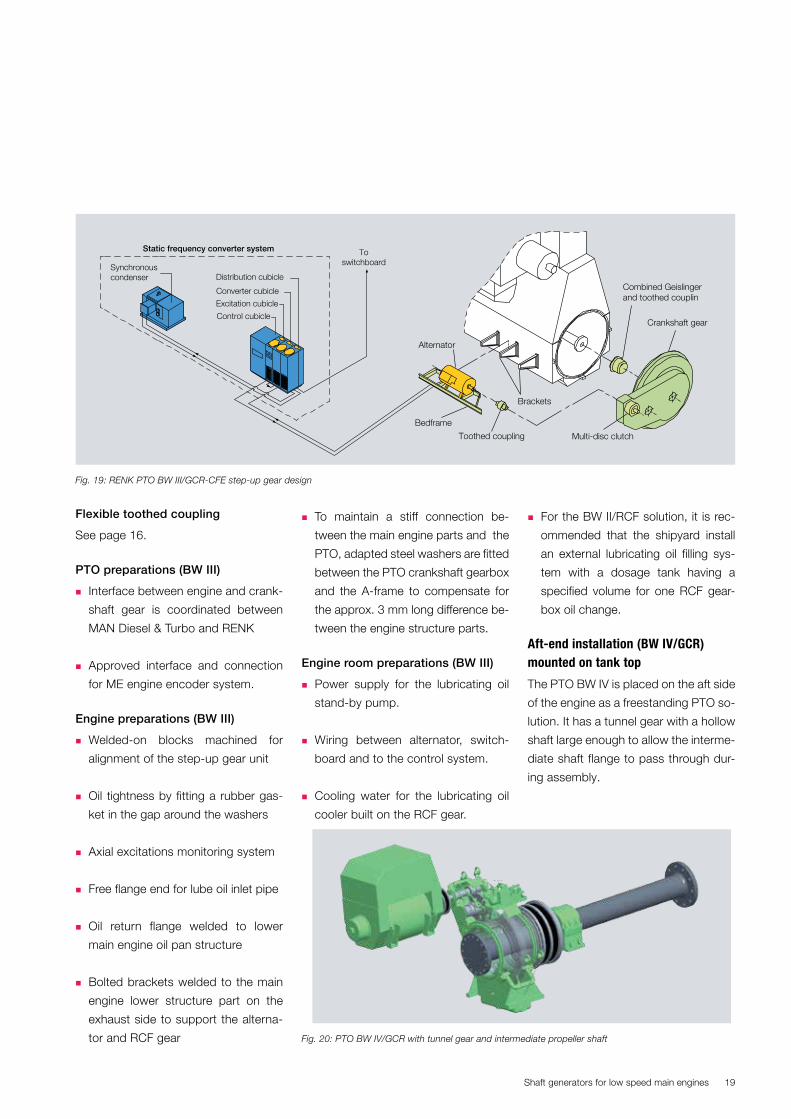
Flexible toothed coupling
See page 16.
PTO preparations (BW III)
� Interface between engine and crank-
shaft gear is coordinated between
MAN Diesel & Turbo and RENK
� Approved interface and connection
for ME engine encoder system.
Engine preparations (BW III)
� Welded-on blocks machined for
alignment of the step-up gear unit
� Oil tightness by fitting a rubber gas-
ket in the gap around the washers
� Axial excitations monitoring system
� Free flange end for lube oil inlet pipe
� Oil return flange welded to lower
main engine oil pan structure
� Bolted brackets welded to the main
engine lower structure part on the
exhaust side to support the alterna-
tor and RCF gear
� To maintain a stiff connection be-
tween the main engine parts and the
PTO, adapted steel washers are fitted
between the PTO crankshaft gearbox
and the A-frame to compensate for
the approx. 3 mm long difference be-
tween the engine structure parts.
Engine room preparations (BW III)
� Power supply for the lubricating oil
stand-by pump.
� Wiring between alternator, switch-
board and to the control system.
� Cooling water for the lubricating oil
cooler built on the RCF gear.
� For the BW II/RCF solution, it is rec-
ommended that the shipyard install
an external lubricating oil filling sys-
tem with a dosage tank having a
specified volume for one RCF gear-
box oil change.
Aft-end installation (BW IV/GCR) mounted on tank top
The PTO BW IV is placed on the aft side
of the engine as a freestanding PTO so-
lution. It has a tunnel gear with a hollow
shaft large enough to allow the interme-
diate shaft flange to pass through dur-
ing assembly.
Fig. 19: RENK PTO BW III/GCR-CFE step-up gear design
Fig. 20: PTO BW IV/GCR with tunnel gear and intermediate propeller shaft

Shaft generators for low speed main engines20
Fig. 21: PTO BW IV/GCR with tunnel gear and hollow segmented flexible damping coupling fitted to the propeller shaft
Fig. 22: PTO BW IV/GCR tunnel gear and alterna-tor
Fig. 23: PTO BW IV tunnel gearbox from RENK
Vulkan Ratoflexible coupling
AlternatorToothedcoupling
Tunnelgear
Shaft generators for low speed main engines 21
A number of gearbox manufacturers
can supply PTO BW IV/GCR solutions
that do not increase the total built-in
length of the propeller shaft and the en-
gine, and the shaft generator can be in-
stalled within the space already available
around the shaft line aft of the engine.
A flexible damping coupling based on
rubber elements is fitted around the in-
termediate shaft. The steel flanges used
for the coupling are made in halves to
allow assembly around the intermediate
propeller shaft. The flexible coupling is
connected between the hollow tunnel
gear shaft flange and the propeller shaft
flange on the engine. Alternatively, it
can be connected to a forged-on flange
anywhere on the intermediate propeller
shaft, which means that the PTO can be
moved further away from the engine.
When operating the PTO, the flexible
coupling only transfers a torque cor-
responding to the power of the shaft
generator.
The PTO BW IV has its own separate
gear-driven lubricating oil system and
an electrically driven built-on lubricat-
ing oil standby pump used to supple-
ment the gear-driven pump during main
engine start-up and in the event of any
malfunctioning of the mechanical gear-
driven pump.
Engine preparations (BW IV)
� No engine preparations for the instal-
lation of the PTO BW IV system are
needed
Engine room preparations (BW IV)
� Tank top foundation for gearbox and
alternator
� Cooling water supply to lubricating
oil cooler
� Electric power supply to lubricating
oil stand-by pump.
� Wiring between alternator, switch-
board and to control system.
The intermediate shaft flange must be
provided with additional screw holes
for the flexible coupling or an additional
forged on flange must be made for al-
ternative PTO positioning further away
from the engine.
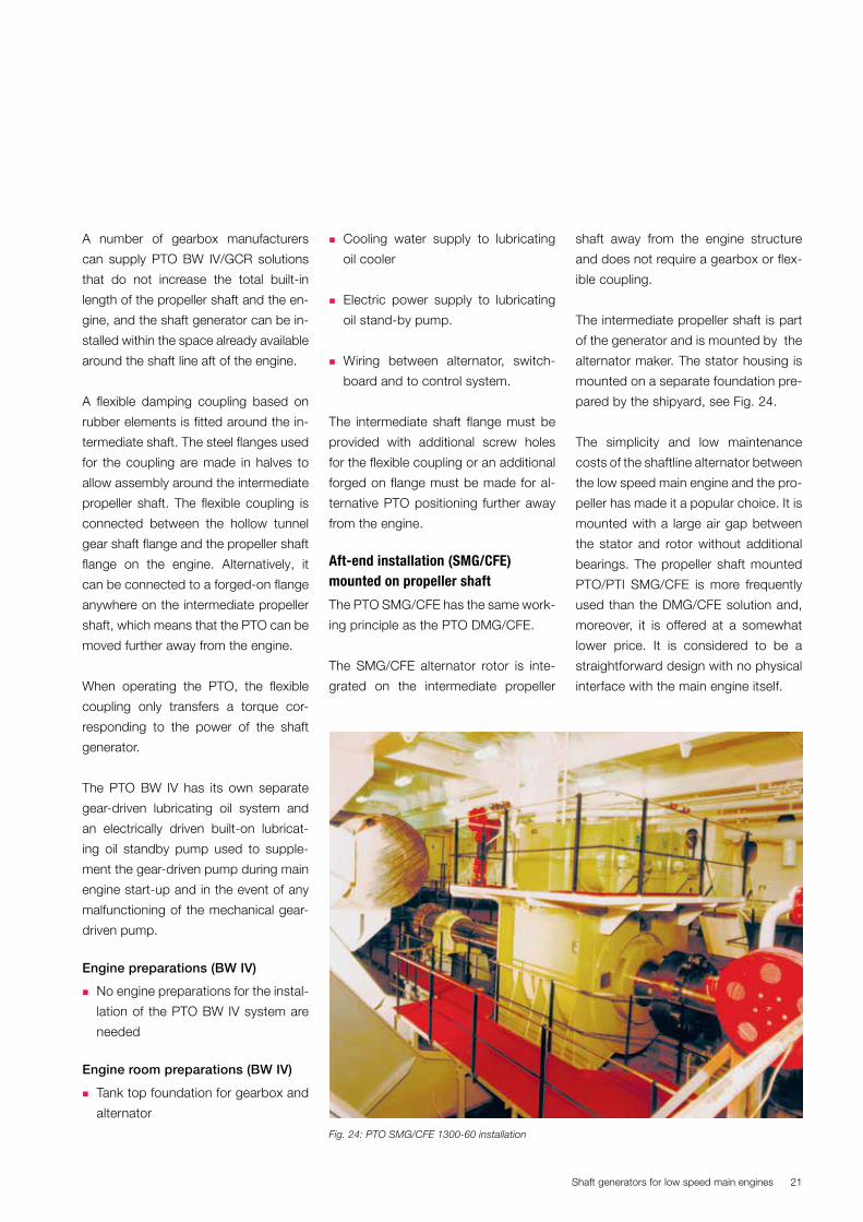
Aft-end installation (SMG/CFE) mounted on propeller shaft
The PTO SMG/CFE has the same work-
ing principle as the PTO DMG/CFE.
The SMG/CFE alternator rotor is inte-
grated on the intermediate propeller
shaft away from the engine structure
and does not require a gearbox or flex-
ible coupling.
The intermediate propeller shaft is part
of the generator and is mounted by the
alternator maker. The stator housing is
mounted on a separate foundation pre-
pared by the shipyard, see Fig. 24.
The simplicity and low maintenance
costs of the shaftline alternator between
the low speed main engine and the pro-
peller has made it a popular choice. It is
mounted with a large air gap between
the stator and rotor without additional
bearings. The propeller shaft mounted
PTO/PTI SMG/CFE is more frequently
used than the DMG/CFE solution and,
moreover, it is offered at a somewhat
lower price. It is considered to be a
straightforward design with no physical
interface with the main engine itself.
Fig. 24: PTO SMG/CFE 1300-60 installation

Shaft generators for low speed main engines22
Engine room preparations
(SMG/CFE)
� Tank top foundation for the alternator
stator housing
� Cooling water supply for water
cooled alternators
� Wiring between alternator, frequency
converter system, switch board and
control system
� For the traditional thyrister converter
solution additional seating for syn-
chronous condenser unit and static
converter cubicles are necessary,
but those can be avoided by the
shaft generator type using the PWM
converter technology.
Front-end PTO installation mounted on engine (DMG/CFE)
The PTO DMG/CFE is a large slow run-
ning alternator with its rotor mounted
directly on the crankshaft, and the sta-
tor housing is bolted to the front-end
engine structure, see Fig. 25.
The DMG/CFE does not require a gear-
box or flexible coupling, and the alter-
Fig. 25: PTO DMG/CFE
Static frequency converter system
Synchronouscondenser
Distribution cubicle
Converter cubicle
Excitation cubicle
Control cubicle
Toswitchboard
Oil seal cover
Rotor
Stator housing
Cooler
Supportbearing
nator is separated from the crankcase
by a plate and a labyrinth seal made by
the PTO supplier.
Depending on the torsion characteristics
and a vibration analysis, additional iner-
tia mass in the form of a tuning wheel
can be added, see Fig. 26.
If shear force and bending moment act-
ing on the fore-end flange of the crank-
shaft exceed the limits, the stator hous-
ing must be prepared with a front-end
support bearing to reduce the load on
the crankshaft.

Shaft generators for low speed main engines 23
� In order to secure the oil tightness a
rubber gasket is placed between the
gearbox and the A-frame.
� Monitor system for axial excitations.
Engine room preparations (DMG/
CFE)
� Foundation for the synchronous con-
denser unit and static converter cu-
bicles.
� Cooling water supply water cooled
alternator.
� Wiring between alternator, frequency
converter, switchboard and to con-
trol system.
Aircooler
Stator housingStuffing box
Crankshaft
Aircooler
Stator housingStuffing box
Crankshaft
Supportbearing
Polewheel
Mainbearing no. 1
Tuning wheelMainbearing no. 1
Standard engine, with directmounted generator (DMG/CFE)
Standard engine, with directmounted generator and tuning wheel
Pole wheel
Fig 26: PTO DMG/CFE structure can be made to accommodate a tuning wheel
In order to reduce weight carried by the
main engine structure further founda-
tions in ship may be necessary in order
to support some large DMG applica-
tion.
The electrical frequency generated de-
pends on the speed of the main engine
and the number of poles used for the
alternator. More poles increase the fre-
quency and diameter of alternator. The
alternator diameter is however con-
strained by ship hull geometry, which
means that alternator is not able to
produce a frequency of 50Hz or 60Hz
without the use a frequency converter
system between the alternator and the
main switchboard.
PTO preparations (DMG/CFE)
� Interface with engine and crankshaft
gear is coordinated between engine
maker and the licensee producing
the engine.
Engine preparations (DMG/CFE)
� ME operation encoder system can
be fitted to aft-end tuning wheel.
� Engine structure built-in stiffness and
strength for bolt connections.
� Weld on blocks machined for align-
ment of the gear unit.
� In order to maintain a stiff connec-
tion between main engine parts and
PTO, adapted machined steel wash-
ers are placed between the PTO
crankshaft gearbox and the A-frame
to compensate for the approx. 3 mm
difference in length between the en-
gine structure parts.
Shaft generators for low speed main engines24
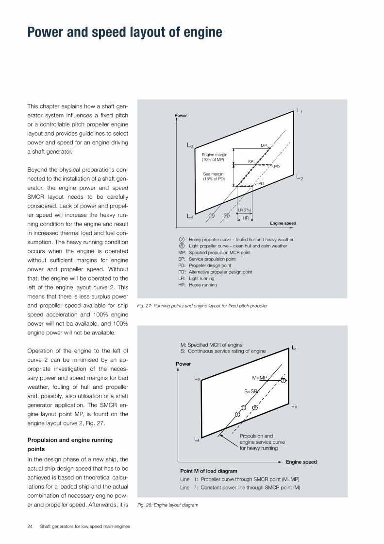
This chapter explains how a shaft gen-
erator system influences a fixed pitch
or a controllable pitch propeller engine
layout and provides guidelines to select
power and speed for an engine driving
a shaft generator.
Beyond the physical preparations con-
nected to the installation of a shaft gen-
erator, the engine power and speed
SMCR layout needs to be carefully
considered. Lack of power and propel-
ler speed will increase the heavy run-
ning condition for the engine and result
in increased thermal load and fuel con-
sumption. The heavy running condition
occurs when the engine is operated
without sufficient margins for engine
power and propeller speed. Without
that, the engine will be operated to the
left of the engine layout curve 2. This
means that there is less surplus power
and propeller speed available for ship
speed acceleration and 100% engine
power will not ba available, and 100%
engine power will not be available.
Operation of the engine to the left of
curve 2 can be minimised by an ap-
propriate investigation of the neces-
sary power and speed margins for bad
weather, fouling of hull and propeller
and, possibly, also utilisation of a shaft
generator application. The SMCR en-
gine layout point MP, is found on the
engine layout curve 2, Fig. 27.
Propulsion and engine running
points
In the design phase of a new ship, the
actual ship design speed that has to be
achieved is based on theoretical calcu-
lations for a loaded ship and the actual
combination of necessary engine pow-
er and propeller speed. Afterwards, it is
Fig. 27: Running points and engine layout for fixed pitch propeller
2 6LR (7%)
Engine speed
Power
MP
Sea margin(15% of PD)
SP
HR
PD´
PD
Engine margin(10% of MP)
Heavy propeller curve – fouled hull and heavy weather2 Light propeller curve – clean hull and calm weather6
MP: Specified propulsion MCR pointSP: Service propulsion pointPD: Propeller design point
LR: Light runningHR: Heavy running
PD´: Alternative propeller design point
Point M of load diagram
Line 1: Propeller curve through SMCR point (M=MP)
Line 7: Constant power line through SMCR point (M)
Engine speed
Power
M: Specified MCR of engineS: Continuous service rating of engine
M=MP
Propulsion andengine service curvefor heavy running
7
S=SP
2
16
Fig. 28: Engine layout diagram
Power and speed layout of engine

Shaft generators for low speed main engines 25
agram can be drawn, see Fig. 29. This
allows the actual load limitation lines of
validated by experimental tank tests for
the optimum operating conditions for
a new ship. The combination of power
and propeller speed obtained from this
analysis is called the ship’s propeller
design point PD, and it is found on the
dashed light running propeller curve 6
in Fig. 28.
Layout for engine driving a fixed pitch propeller
For a fixed pitch propeller layout, the
propeller speed depends on the resist-
ance from wind, waves and fouling of
hull and propeller.
When the ship has been sailing for some
time, the hull and propeller will become
fouled and the resistance acting on the
ship when sailing will be increased.
For a new ship without a fouled hull
and propeller trading at 15% sea mar-
gin, which means a little headwind and
small waves, about 15% more power
is necessary to achieve the same ship
speed compared to a situation of no
wind and no waves. In such circum-
stances the heavy running propeller
equilibrium pretty much follow the light
running curve, about 0.5% to the left of
the dashed light running propeller lay-
out curve.
However, for a very bad weather and
fouled hull condition, the propeller equi-
librium will be formed even more to the
left, and for that condition the engine
power and propeller speed layout has
to be prepared. To meet that require-
ment, it is normal practice to use an
extra engine power margin of 15%. To
ensure that a sufficient propeller speed
margin is available. Our recommen-
Fig. 29: Engine load diagram
4
7
5
2 61
M: Specified MCR of engineS: Continuous service rating of engine
Engine speed
M
Propulsion and engine servicecurve for heavy running
3.3% M
Power
S
3’
5% M
5% L1
4
3
75
2
61
dation for the propeller speed margin
(LRM) is between 4 to 10%.
Once the SMCR point MP has been
found in the layout diagram, the load di-
Fig. 30: Engine layout diagram for engine driving a shaft generator (normal case)
Shaf
t gen
erat
or
Propulsion curvefor heavy running
7
Engine service curvefor heavy running
MP
SGS
SG
SP
Engine speed
Power M
M: Specified MCR of engineS: Continuous service rating of engine
Point M of load diagram
Line 1: Propeller curve through SMCR point (M=MP+SG)
Line 7: Constant power line through SMCR point (M)
1 2 6

Shaft generators for low speed main engines26
the diesel engine to be found from the
engine load diagram.
Layout for engine prepared for driv-ing a fixed pitch propeller and shaft generator
For engines driving a shaft generator,
additional power and speed margins
must be considered to ensure opera-
tion hours for PTO during ship accel-
eration, bad weather and fouled hull
conditions. In many cases, the engine’s
SMCR power is found by a simple addi-
tion of the maximum power consumed
by the shaft generator to the propul-
sion point MP, Fig. 30. Accordingly, the
specified maximum continuous rating
point can be found by the calculation:
M=MP+SG, where SG shows the me-
chanical power needed for operating
the shaft generator including the ef-
ficiency loss through the shafting and
gearbox.
If the ship is trading at a low-load ship
operating profile, a further light running
propeller speed margin should be con-
sidered, as the shaft generator opera-
tion curve, through M, at low-load op-
eration is relatively closer to the torque/
speed limit curve 4, Fig. 31., and there-
fore has less propeller speed available
for a heavy running condition caused
by bad weather or fouled hull.
With the SMCR point established at
M, the combined ship propulsion shaft
generator layout and the load diagram
can be drawn, Fig. 31.
The extra power margin for a shaft
generator will ensure surplus power for
ship acceleration in bad weather condi-
tions, while keeping a suitable propeller
Fig. 31: Engine load diagram for engine driving a shaft generator (normal case)
Fig. 32: layout and Load diagram with the ship acceleration curve
L4
Shaf
t gen
erat
or
Propulsion curvefor heavy running
3.3% M
S
SG
5% M
5% L1
L1
L2
L3
M
Engine service curvefor heavy running
MP
SP
Engine speed
Power
M: Specified MCR of engineS: Continuous service rating of engine
7
7
5
5
4
4
1
1
2
2
6
3 3’
6
L4
Shaft
gen
erat
or
Heavy runningpropulsion curve
Ship acceleration curve
S
SG
L1
L2
L3
M
MP
SP
75
4 1 2
3 3’
6
Heavy running(PTO) service curve

Shaft generators for low speed main engines 27
curve distance to the torque/speed limit
curve 4, Fig. 32.
Special layout for engine with fixed pitch propeller and shaft generator
An engine layout for a shaft generator
operated at maximum engine power
may put the intended SMCR point M’
of the engine outside the top of the
blue layout diagram. Consequently,
one more cylinder is necessary to meet
the power demand. Selecting an extra
cylinder for the engine implicates extra
costs and additional space require-
ments in the engine room. However,
selecting one cylinder more for the ME
can be avoided by restricting the load
on the shaft generator when the engine
is operated at close to the SMCR point.
By doing so, the propulsion point MP
can still be reached on the propulsion
curve 2, if a genset covers the partial
electric power gap between line 1 and
the horizontal line 7.
However, such a situation only occurs
rarely, as ships rather infrequently op-
erate in the upper propulsion power
range.
Point M is the highest possible engine
power available and it is found at the
Fig. 33: Special engine layout, with PTO (special case)
Fig. 34: Reduced power from the shaft generator close to specified propulsion point (special case)
Shaf
t gen
erat
or
Propulsion curve for heavy running
SG
S
1
7
2
Engine service curvefor heavy running
MP
SP
MM´
Engine speed
Power
M´: Intended specified MCR of engineS: Continuous service rating of engineM: Recommended SMCR point of load diagram
Point M of load diagramLine 1: Propeller curve through service point S
M: Intersection between line 1 and line L1- L3Point
6
M´: Intended specified MCR of engineS: Continuous service rating of engineM: Recommended SMCR point of engine
Shaf
t gen
erat
or
Propulsion curvefor heavy running
3.3% M
SG
S
5% M
5% L1
Engine service curvefor heavy running
MP
SP
MM´
Engine speed
Power
3’
6
6
2
2
3
7
7
5
5
1
1
4
4

Shaft generators for low speed main engines28
intersection between line L1-L3 and SG
operation curve 1.
Engine layout with controllable pitch propeller and shaft generator
The hatched area shows a speed range
between 96.9 and 100% of the speci-
fied MCR speed for an engine driving a
shaft generator.
The service power point S can be lo-
cated at any point within the hatched
propeller speed range. Electric power
generated from the shaft generator is
available within the hatched area.
Although the speed margin is not rele-
vant for a CP propeller, as the pitch can
be adjusted to meet the requested pro-
peller speed, it is still relevant to inves-
tigate the power margin for PTO. This
applies if the ship speed must be main-
tained during heavy weather and fouled
hull conditions while retaining the ability
to operate the shaft generator.
Layout for engine driving a fixed pitch propeller and shaft generator/motor
In some projects for larger container
ships with a waste heat recovery sys-
tem installed in combination with a shaft
generator and a shaft motor (PTO/PTI),
it is ensured that any surplus electric
power generated from the waste heat
recovery can be utilised for shaft pro-
pulsion by the shaft motor.
Depending on the PTO and PTI power
available, the advice on an engine lay-
out with a combined PTO alone or PTI
alone solution can be followed.
In this example, a large shaft motor
has been installed. The contractual
ship speed is met at the service point
Fig. 35: Example with controllable pitch propeller running with a combinatory curve.
Min.speed
M
3.3%M
5
4
1
75%M
5%L1
Recommended rangefor shaft generatoroperation withconstant speed
3
5
1
7
Combinator curvefor loaded shipand incl. sea margin
Max.speed
M: Specified MCR of engineS: Continuous service rating of engine
Engine speed
Power
4
S
Fig. 36: Engine layout diagram for engine operating with a shaft motor (PTI)
Point M of load diagram:Point PD: Propeller design pointLR’: Normal light running (3-7%) of propellerPoint X: SMCR power on line 2’Point M: Same power as X but with X = 2.2% lower rpm
1
6’
6
2’
7
2
L4
SP
PD
LR’S
X
X = 2.2%
PTI
Engine margin(10% of M)
Sea margin(15% of PD)
PTI
PTI
M
L1
L3
L2
Engine speed
Power
Real propeller curve for heavy running
Real propeller curve for light running
Engine service curve for heavy running
Engine service curve for light running

Shaft generators for low speed main engines 29
SP=S+PTI and is based on the main en-
gine propulsion power S and the power
contribution from the PTI shaft motor.
In Fig. 36, for the purpose of illustration,
the propeller design point PD meets the
ship speed in calm weather and clean
hull condition. The resulting MCR point
X is valid for shaft motor operation and
is based on the normal light running
factor LR’ sea and engine margin.
When it comes to the engine layout,
and operating the shaft generator
(PTO) at engine part load (low load), it is
recommended to choose the specified
MCR engine speed M about X=2.2% to
the right of the point X, thereby forming
the engine layout curve 1 to which the
engine should be selected.
From curve 1, the real propeller light run-
ning factor LR can be found by using the
calculation LR=LR’– X, and the load dia-
gram of the main engine can be drawn
around the MCR point M.
Engines running with a PTI may some-
times need the possibility to operate
with increased light running outside the
standard load diagram. In such cases,
provided the torsion vibration conditions
permit, a speed derated engine offers
the possibility for extended speed limit. Fig. 37: Engine load diagram for engine operating with a shaft motor (PTI) and the light-running extended speed limit possibility shown by the hatched area.
Engine speed
Power
Line 1 : Propeller curve through M – layout curve for engineLine 2’ : Real propeller curve for heavy runningLine 2 : Heavy running curve for engine with PTI in operationLine 3 : Normal speed limit curveLine 3’ : Extended speed limit curve (provided torsional vibrations permit)Line 6’ : Real propeller curve for light running – layout curve for propellerLine 6 : Light running curve for engine with PTI in operationLR’ : Normal light running 3-7% of propellerLR = LR’ -X : Real light running of propeller (compared to curve 1)
M : Specified MCR of main engineS : Continuous service rating of main engineSP : Service propulsion power = engine service power S + PTI
L4
Power
Tak
e In
SP
LR’LR
2.2% MX=
3.3 M% 5% M
S
X
PTI PTI
M
L1
L3
L2
1
4
6’
6
3 3’
2’
75
5% L1
2
Real propeller curve for heavy running
Real propeller curve for light running
Engine service curve for heavy running
Engine service curve for light running

Shaft generators for low speed main engines30
When dimensioning the layout of the
propeller and shafting system, the con-
tribution from extra PTI power for pro-
pulsion must also be taken into account.
Engines with small PTO applications
The gear-based PTO BW I, BW II, BW III
and BW IV systems all incorporate a flex-
ible coupling for protection of the gears
against hammering caused by torsional
excitations from the engine.
When the shaft generator power out-
put is less than 10% of the main engine
power, the vibration modes of the shaft
generator system will not influence the
vibration modes of the propulsion shaft
system. The choice and design of a pro-
pulsion shaft system can therefore be
made without making considerations to
a possible shaft generator later on.
The PTO/GCR gear constant ratio is
normally designed to operate at 100%
SMCR speed, and it is therefore tuned
so that the critical speed of significant
torsional vibration (t/v) orders is placed
outside the 80-120% range of propeller
speed.
The flexible coupling for the PTO/GCR
types is selected on the basis of the mis-
firing conditions and normal service con-
ditions. The normal service conditions
are therefore harmless to both the flex-
ible coupling and the gear. Irrespective of
the number of engine cylinders, a mis-
firing incident will increase the 1st order
excitation close to the natural frequency
substantially, which explains why it is es-
sential to tune the natural frequency of
the 1-node vibration mode in accord-
ance with the engine speed.
The position of the natural frequency for
the 1-node vibration mode in the shaft
generator branch mainly depends on the
torsional flexibility of the flexible coupling
and the inertia of the alternator. As a rule
of thumb, the lowest natural frequency
of the shaft generator branch should not
be less than 120%, or more than 80%,
of the frequency corresponding to the
SMCR engine speed. This means that
either under- or overcritical vibration
conditions for 1st order excitation can
be obtained with a satisfactory safety
margin.
For an incorporated alternator clutch,
the design criteria and operation of
clutch normal takes place according to
following:
� Alternator engaged: overcritical run-
ning (1st order critical speed at 55-
80% x SMCR speed)
� Alternator disengaged: undercritical
running (1st order critical speed above
120% x SMCR speed, higher orders
to be considered).
For the PTO/RCF (RENK constant fre-
quency), which normally operates at be-
tween 70% and 105% of SMCR engine
speed, the flexible coupling design leads
to a natural frequency of between 50-
60% of the frequency at SMCR speed.
Operation during misfiring is often pro-
hibited, so if the natural frequency in-
crease, due to a more rigid coupling
(breakage) or in the event of a misfiring
event, the alternator must be declutched
by the incorporated RCF gear clutch.
When the alternator is declutched, the
magnitude of the alternator’s inertia it-
self must allow the natural frequency of
the shaft generator branch, which re-
mains coupled to the engine, to ‘jump’
to a sensibly higher frequency than the
corresponding frequency at 105% MCR
speed. In this respect, it may be neces-
sary to tune the inertia of the alternator
by fitting an additional mass (a tuning
wheel) to the alternator side of the clutch.
The DMG/CFE and the SMG/CFE do not
incorporate a gear or a flexible coupling,
but the inertia of the rotor may naturally
influence the torsional layout of the shaft-
ing.
Engines with large PTO applications
Such types of ships like shuttle tankers,
which have a high demand for electric
power, may use one or two large BW IV
shaft generators for the electricity pro-
duction. They are normally operated with
a controllable pitch propeller and some-
times also a propeller shaft clutch.
For such an installation, the torsional
vibrations analysis is very complex and
require a careful investigation of all pos-
sible operating modes during the design
stage.
In general, the flexible coupling between
the propeller shaft and the PTO should
be sufficient to ensure a natural fre-
quency in the shaft generator system at
below 75% of the corresponding engine
frequency when the generator is oper-
ated. If it is not, it could alternatively be
designed to have a natural frequency of
150%, corresponding to the frequency
of a main engine when a generator is op-
erated. This setup will provide main criti-
cal resonances (4th, 5th and 6th order)
in the shaft generator system at very low
speeds, and in case of a misfiring when
Torsion vibration aspects

Shaft generators for low speed main engines 31
the 1st and 2nd order excitation be-
come dominant, the resonance is found
outside the shaft generator operating
speed.
Adjusting of the natural frequencies will
normally require very flexible couplings.
The speed governor is an integrated
part of the ME control system and it
does not normally require special atten-
tion.
However, for plants where the power of
the PTO/PTI exceeds 15% of the main
engine’s L1 MCR power, and the PTO/
PTI is driven trough a flexible coupling
and/or a clutch, special precautions
may be necessary to maintain the sta-
bility of the speed control.
Such plants must be evaluated by MAN
Diesel & Turbo to determine any nec-
essary extra features such as speed
measurement on the generator/mo-
tor side of the elastic coupling and/or
clutch state signals.
Design requirements for shaft genera-tor makers
When a shaft generator is applied it
must be designed to operate on the
conditions of the main engine/propul-
sion system.
� A constant speed shaft generator
must be able to accept a ±5% sta-
tionary and ±10% transient speed
variation relative to the nominal
speed. The shaft generator must be
able to operate at least 5 seconds in
the transient range without setting off
an alarm or initiating disconnection
of the shaft generator.
� A variable speed shaft generator
must accept at least the same speed
variations within and at the end
points of the defined shaft generator
operating range.
� A variable speed shaft generator re-
quiring a wide operating range below
75% MCR engine speed must use
the absolute rpm limits calculated for
75% engine speed as tolerance.
In rough weather, the speed variations
will increase and may reach a level
where shaft generator operation is not
possible and, accordingly, the electric-
ity production must be shifted to the
auxiliary engines.
Engine Governing System

Shaft generators for low speed main engines32
PTO advantages
Operating a shaft generator will make it
possible to:
1. Limit the operating time on the four-
stroke genset engines for mainly ma-
noeuvring operations in port.
2. Generate the same amount of elec-
tric power at a lower cost.
3. Save fuel for the charter.
4. Reduce the maintenance costs by
saving operating time on the four-
stroke gensets.
5. Improve the steam production from
the main engine, thanks to the high-
er engine load and exhaust gas tem-
peratures.
Small space requirement
Both the BW III installed close to the en-
gine or the BW IV installed in the shaft
line takes slightly more further space
than is already set aside for the engine
installation.
The DMG/CFE installed on the engine
front end and the SMG/CFE installed in
the shaft line need extra space elsewhere
in the engine room for the synchronous
condenser and the control cubicles.
Low investment cost (PTO/GCR)
The investment cost depends on the
generator type and make, but normally
the PTO/GCR shaft generator is avail-
able for a relatively low price, whereas
the PTO/RCF and PTO/CFE frequency
control types are relatively expensive.
The RCF type from RENK comes with
an inexpensive installation as no further
frequency control cubicles are needed in
the engine room arrangement.
The shaft generator requires no separate
or just a simple foundation, no exhaust
gas system, and only a few connections
to the auxiliary equipment. The installa-
tion time for a shaft generator is short.
Reliability
Shaft generators are generally consid-
ered to be highly reliable.
Low time use for maintenance
Planned maintenance of a PTO during
the first years of operation only involves
regular checks of proper functioning and
regular replacement of the lubricating oil
and oil filter if the shaft generator has a
separate lubricating oil system.
Low spare parts costs
As a result of the high reliability and low
spare parts consumption for the planned
overhauls, maintenance costs are low.
Long lifetime
A low wear rate for shaft generator parts
means long lifetime.
However, bearings, mechanically-driven
oil pumps, friction clutches, etc., will
need replacement or reconditioning after
many years in operation.
Saving running hours on the gensets
When the shaft generator can cover the
full electric power consumption on the
voyage, one genset can be omitted for
installation, and the running hours on
the remaining two gensets are reduced,
and they could perhaps be replaced by
smaller and cheaper high-speed genset
installations.
Low noise
The noise level of a PTO is considerably
lower than the noise level from a genset.
PTO can improve ship EEDI figure
PTO disadvantages
Increased spare parts costs
Normally, more parts are needed for gen-
sets, unless fewer gensets are installed.
No power production in port
Electric power from a shaft generator
is not available while in port, unless a
clutch is installed between the PTO and
the propeller shaft. This can be seen on
some shuttle tankers. In that case, the
electric power used for cargo pumping
is available from the shaft generator if the
propeller is de-clutched.
Higher load on main engine
Because of the higher load on the main
engine when operating the shaft gen-
erator, the specific fuel oil consumption
and the cylinder oil consumption may in-
crease depending on the engine layout.
Reduced CPP propeller efficiency at
reduced ship speed
PTO/GCR electric power production at
low load and SMCR propeller speed im-
plicate reduced propeller efficiency.
No long-time parallel running ability
for PTO/GCR
The PTO/GCR cannot run in parallel with
the four-stroke generators, except dur-
ing load take-over (shifting the electric
power production from gensets to PTO
and vice versa).
More complex shaft arrangement
Gears and flexible couplings are not
used for two-stroke diesel engines
used only for propulsion, and the inertia
from those components may influence
the torsional layout of the shafting.
A PTI can deteriorate the EEDI figure
if used for increasing the ship speed.
Pros and cons of shaft generators

Shaft generators for low speed main engines 33
This chapter gives a comparison of
the operating costs for a typical feeder
container vessel equipped with CP pro-
peller.
The first engine room layout has three
diesel gensets and the second engine
room layout has a low-cost shaft gen-
erator PTO/GCR combined with two
diesel gensets.
A CP propeller is used for both layouts,
but in order to utilise a low-cost PTO/
GCR, the main engine is running with
a constant speed for the whole power
range.
Engine room layout with gensets
One 7S50ME-B8 main engine, SMCR
9,760 kW at 127 rpm, NCR 80%.
One propeller running at reduced pro-
peller speed and engine power (combi-
nator propeller curve).
Three 6L23/30H Mk 2 diesel gensets.
Propulsion time and load profile:
1. 15% at 90% engine power
2. 40% at 80% engine power
3. 35% at 70% engine power
4. 10% at 10% engine power
Engine room layout with shaft
generator
One 7S50ME-B8 main engine, SMCR
11,060 kW at 127 rpm, NCR 80%.
One propeller running at constant
speed.
One PTO BW IV/GCR/1,200 shaft gen-
erator.
Two 6L23/30H Mk 2 diesel gensets.
The cost comparison is made at run-
ning points for exactly the same ship
speed, but due to the efficiency loss
implication for CP propeller running at
constant propeller speed propulsion,
powers are increased at part load op-
eration for the engine running with PTO.
Time at sea: 250 days/year
Time in port: 115 days/year
Electric load at sea: 900 kW
Electric load in port: 500 kW
Operation costs for fuel oil, lubricating
oil and maintenance have been com-
pared, and it is concluded that the:
1. annual fuel and lube oil cost savings
are 2% lower for the PTO alternative.
2. annual maintenance cost savings are
5% lower for the PTO alternative.
3. annual total operation cost savings
are 2% lower for the PTO alternative.
The extra investment cost for one shaft
generator compared with one diesel
genset corresponds to a payback time
of three years. However, the investment
cost of both the PTO and the gensets
may differ significantly depending on
the supplier origin, but the installation
cost is expected to favour the shaft
generator layout.
Other installation aspects may also af-
fect installation costs, such as one ad-
ditional cylinder for the main engine in
order to ensure surplus power for the
PTO operation and ship acceleration,
together with appropriate engine derat-
ing for improved engine efficiency How-
ever, any extra costs for one more main
engine cylinder, its increased capacity
for auxiliary equipment, and the eco-
nomic impact from a possible increased
engine room length are not included.
Many factors influence the decision for
PTO, and whether the installation of a
shaft generator is attractive or not is
up to the shipowner. In the past, many
shipowners have preferred engine room
layouts that include three gensets, most
likely because of the simplicity and well-
known design offered by the yards.
Economic comparison between engine room layouts

Shaft generators for low speed main engines34
The engine-mounted PTO BW III/RCF
is available for all engines larger than
40 bore.
Small ships installed with two-stroke
engines smaller than 40 bore and run-
ning with a fixed pitch propeller, will
typically be fitted with the PTO BW
II/RCF type, which offers an electric
power capacity of 250-700 kW.
The PTO BW III/GCR is mostly used
for 50 and 60 bore engines having an
electrical output of 800-1,800 kW.
For a large container vessel equipped
with a fixed pitch propeller and trading
with a large number of reefer plugs, the
PTO SMG/CFE type is often be speci-
fied with an electrical capacity of some
2,000 to 3,500 kW.
The most frequently installed shaft
generators are the BW IV/GCR, SMG/
CFE, BW III/RCF and BW II/RCF types
in the power range from 0.5 to 3.5 MW.
The GCR solutions are typically used
in combination with a controllable pitch
propeller. The PTO BW II/GCR and
PTO IV/GCR are used on container
vessels or chemical tankers with 60-
cm bore engines or smaller and with
an electrical output of 500-1,200 kW.
Fig. 38: Large PTO SMG/CFE installed on a large container vessel.
Typical Shaft Generator Applications
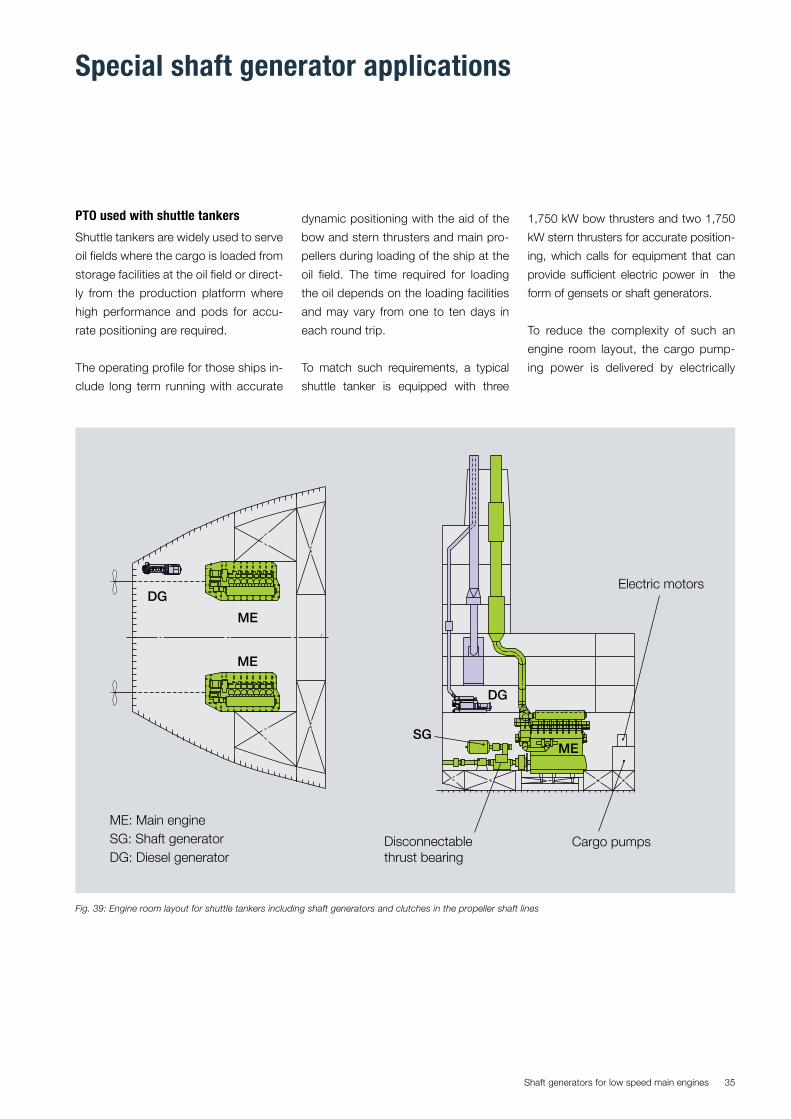
Shaft generators for low speed main engines 35
PTO used with shuttle tankers
Shuttle tankers are widely used to serve
oil fields where the cargo is loaded from
storage facilities at the oil field or direct-
ly from the production platform where
high performance and pods for accu-
rate positioning are required.
The operating profile for those ships in-
clude long term running with accurate
Fig. 39: Engine room layout for shuttle tankers including shaft generators and clutches in the propeller shaft lines
Disconnectablethrust bearing
DG
ME
ME
DG
ME: Main engineSG: Shaft generatorDG: Diesel generator
Electric motors
MESG
Cargo pumps
Special shaft generator applications
dynamic positioning with the aid of the
bow and stern thrusters and main pro-
pellers during loading of the ship at the
oil field. The time required for loading
the oil depends on the loading facilities
and may vary from one to ten days in
each round trip.
To match such requirements, a typical
shuttle tanker is equipped with three
1,750 kW bow thrusters and two 1,750
kW stern thrusters for accurate position-
ing, which calls for equipment that can
provide sufficient electric power in the
form of gensets or shaft generators.
To reduce the complexity of such an
engine room layout, the cargo pump-
ing power is delivered by electrically

Shaft generators for low speed main engines36
driven pumps, instead of hydraulically
driven pumps.
An efficient propulsion system that
meets the above requirements is the
diesel-mechanical twin propulsion sys-
tem with two low speed main engines
and CP-propellers, shaft generators
and propeller shaft clutches.
In port, the propeller can be discon-
nected and the main engine can be
utilised for electric power generation
without turning the propeller.
However, for safety reasons, a study
of the engine acceleration behavior is
required to establish the impact of an
immediate loss of electrical load on
the shaft generator when the propel-
ler is disconnected by the clutch. Such
a study normally results in the setting
of a minimum level of inertia for the al-
ternator, increased requirements to the
engine control system, including an ad-
vanced electronic governor with an ad-
ditional overspeed shutdown feature to
controlling a fuel cut-off device.
For safety reasons, the flexible coupling
between the PTO and the intermediate
shaft has a built-in torsion limiting de-
vice. If the flexible elements break, the
device will transmit the torque by the
help of steel parts until the safety sys-
tem has shut down the engine.
By using the main engine and PTO when
the propeller is de-clutched, the speed
of the cargo pumps can be adjusted
simply by varying the engine speed to
control the electrical frequency.
A frequency converter layout is neces-
sary if the shaft generator is serving
electric power for all consumers, at
all possible conditions during port op-
eration, sea state, dynamic positioning
and where, in some of these load con-
ditions, the engine speed is not kept at
a constant level. Alternatively, one gen-
set must serve electric power for critical
consumers.
Fig. 40: Propeller disconnected by clutch while low speed engine is driven the shaft generator
Shaft generator G1motor M1 1,800 rpmPTO load max. 1,400 kW
Clutch-engaged
Main engine
Propeller-0 rpm
120 rpm
PSC - Coupling
Propeller shaft disconnected
Main engine driving the shaft generator for cargo pumping
PTO gear

Shaft generators for low speed main engines 37
Auxiliary electric propulsion system
An auxiliary propulsion system for loi-
tering operations is especially of in-
terests for projects involving gas and
chemical tankers installed with small
bore low speed engines equipped with
a controllable pitch propeller.
MAN Diesel & Turbo can deliver an aux-
iliary system including electric propul-
Fig. 42: gensets driving the alternator/motor while the low speed main engine is disconnected from the propeller shaft.
Shaft generator G1motor M1 1,800 rpmPTO load max. 1,400 kW Clutch-C2-engaged
Clutch-C1-disengaged
Main engine
Propeller-85 rpm
0 rpm
2 Speed PTO / PTI gearRENK KAZ coupling
Fig. 41: Auxiliary propulsion system for low ship speed operations.
Oil distribution ring
Generator/motorHydrauliccoupling
Two-speedtunnel gearbox
Shaft Clutcher Main engine
Intermediatebearing
Flexiblecoupling
Hydrauliccoupling
sio, clutch, two-speed tunnel gearbox,
and a generator/motor that can drive
the propeller by means of the shaft
generator now operating as an electric
motor powered by a number of gen-
sets.
Before operating the system, the main
engine is disengaged by the clutch,
which is integrated on the shafting and
installed between the tunnel gearbox
and the main engine.
A combined propulsion mode includ-
ing both the main engine and genera-
tor/motor as power take-in is possible,
when increased propulsion power is
needed in order to maintain the ship
speed in rough weather conditions, or
if surplus electric power from a waste
heat recovery system is available.
When the propeller shaft clutch is en-
gaged, and the main engine is running,
the clutch statically transfer the thrust
force from the propeller to the main
engine`s thrust bearing.
When disengaged, Fig. 42, the clutch
build-in thrust bearing transfer the aux-
iliary propeller thrust force to the engine
thrust bearing.
Before starting up in auxiliary propul-
sion mode, a lower gear is needed from
the gear box to enable the generator/
motor to turn the propeller shaft.
Starting the generator/motor in auxiliary
propulsion mode is done with the help
from a start transformer and the two-
speed gear box built-in friction clutch,
allowing the propeller a clutch-in at full
alternator/motor speed where the full
torque is available.
The requirements of some classifica-
tion societies differ according to wheth-
er the auxiliary propulsion system has
been prepared as a take home system
in the event of a main engine failure at
sea, or as a take away from quay loiter-
ing propulsion system.

Shaft generators for low speed main engines38
The auxiliary propulsion system of-
fered by MAN Diesel & Turbo fulfils the
requirements of both alternatives, pro-
vided sufficient electric power for aux-
iliary propulsion is available from the
gensets. Auxiliary propulsion controlled
from the engine control room and/or
bridge can quickly be established by
the system, even with unmanned en-
gine room. Re-establishing of normal
operation requires attendance in the
engine room, but it can be done within
a few minutes.
Auxiliary hydraulic propulsion system
In 2006, as an alternative to the genera-
tor/motor take-in solutions with gearbox
and electric motor powered by gensets,
Marinvest developed the MAPS auxiliary
hydraulic propulsion system for tankers
equipped with hydraulically driven cargo
and ballast pumps. When the hydraulic
propulsion system is engaged, the hy-
drauic power packs are used for driving
the shaft.
The special patented propeller shaft
clutch developed by Marinvest is used
for disconnecting the main engine.
In normal service, the rigidness of the
shaft line is ensured by a bolted con-
nection, and the MAPS system is fully
disconnected and at rest. In this way,
there is no wear and tear on the system.
The engagement of the MAPS system
for alternative propulsion mode takes
a trained crew about 15 minutes. In
this procedure, the special Marinvest
propeller shaft clutch is disengaged by
removing the bolts connecting it to the
main engine and inserting the bolts that
engage the hydraulic drive.
Fig. 44: The principle of MAPS, the alternative hydraulic propulsion system
Fig. 45: When disconnected from the main engine, MAPS can be used for take-away from quay or loiter-ing operations
Fig. 43: Main engine driving the propeller while the electric power is generated by the generator/motor
Shaft generator G1motor M1 1,800 rpmPTO load max. 1,400 kW Clutch-C2-disengaged
Clutch-C1-engaged
Main engine
Propeller-120 rpm
120 rpm
2 Speed PTO / PTI gearShaft Clutch
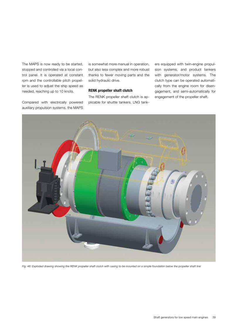
Shaft generators for low speed main engines 39
The MAPS is now ready to be started,
stopped and controlled via a local con-
trol panel. It is operated at constant
rpm and the controllable pitch propel-
ler is used to adjust the ship speed as
needed, reaching up to 10 knots.
Compared with electrically powered
auxiliary propulsion systems, the MAPS
Fig. 46: Exploded drawing showing the RENK propeller shaft clutch with casing to be mounted on a simple foundation below the propeller shaft line
is somewhat more manual in operation,
but also less complex and more robust
thanks to fewer moving parts and the
solid hydraulic drive.
RENK propeller shaft clutch
The RENK propeller shaft clutch is ap-
plicable for shuttle tankers, LNG tank-
ers equipped with twin-engine propul-
sion systems, and product tankers
with generator/motor systems. The
clutch type can be operated automati-
cally from the engine room for disen-
gagement, and semi-automatically for
engagement of the propeller shaft.

Shaft generators for low speed main engines40
PS-clutch size
Torque Thrust engaged (max)
Thrust disengaged
PSC length
Spacer length
Max. Outer diameter
Flange diameter
PSC weight
Spacer weight
kNm kN kN mm mm mm mm tons tons
32 320 600 125 1.500 400 700 600 3,80 0,3
63 600 1.040 208 1.650 600 870 645 4,80 0,5
85 850 1.250 280 1.775 675 950 750 6,50 0,8
132 1.260 1.600 364 1.875 750 1.000 850 8,20 1,1
225 2.150 2.600 520 2.350 1.000 1.230 1.070 14 2,3
355 3.400 3.500 650 2.650 1.150 1.430 1.250 22 3,6
480 4.600 4.800 900 3.050 1.300 1.680 1.400 33 5,1
800 7.800 7.500 1.600 3.600 1.450 1.930 2.050 44 6,5
RENK propeller shaft clutch selection example:
Main engine power:................................................................................................................................... P = 12,640 kW
Main engine speed: ....................................................................................................................................... n = 127 rpm
Power factor: ...............................................................................................................P / n = 12,640 kW / 127 rpm = 99
Selected clutch size: ......................................................................................................................................... PSC 132*
Remarks:
* Coupling selection to be checked for compliance with class requirements for propeller shafting.
** PSC flange diameter adjustable according to main engine and propeller flange.
Fig. 47: The RENK propeller shaft clutch dimensioning
RENK propeller shaft clutch
disengagement steps
1. Stop engine
2. Block engine
3. Slow down ship until maximum per-
missible shaft torque is achieved
(approx. 10% of nominal torque)
4. Disengage clutch.
RENK propeller shaft clutch
engagement steps
1. Start hydraulic clutch pump
2. Engage turning gear of main engine
3. Engage disc brake
4. Align clutch by means of turning gear
and electric alignment indication
5. Disengage turning gear
6. Engage clutch
7. Disengage disc brake.

Shaft generators for low speed main engines 41
Waste heat recovery systems
The amount of air required for the diesel
engine’s combustion process is lower
than what is obtainable with high-effi-
ciency turbochargers. So when high-ef-
ficiency turbocharger systems are avail-
able, it is possible to reduce the supply
of energy to the turbocharger’s exhaust
gas turbine and utilise the excess ex-
haust gas heat for power production at
engine loads above 45% of SMCR main
engine power.
MAN Diesel & Turbo has published a
paper on waste heat recovery (Ref. 1),
which describes the more advanced
combined WHR systems that also uti-
lise the excess energy from steam for
electric power production.
Power turbine generator
Electric power production from a waste
heat recovery system utilising only
the exhaust gas can be supplied by a
power turbine generator system when
by-passing a percentage of the exhaust
gas to a power turbine placed on a
frame in the proximity of an alternator.
The power turbine generator system
available from MAN Diesel & Turbo can
be operated as a stand-alone solution
to supply all the electric power on the
voyage.
MHI hybrid turbocharger
Electric power production from the
exhaust gas can also be effected by
means of an advanced turbocharger
solution designed with an integrated al-
ternator in the shaft line. Such a system
is available from Mitsubishi Heavy In-
dustries and is known as the MHI MAG
hybrid turbocharger system.
In the same way as a the standard tur-
bocharger, the MAG hybrid turbocharg-
Fig. 49: Cutaway view of MHI MET-MAG hybrid turbocharger
Fig. 48: Schematic diagram of a power turbine generator system
Board gridEfficiency between 3 to 5% ofmain engine SMCR power depending on size
Turbochargers
Funnel (boiler)
GeneratorCoupling
Exhaust gas turbine
Main engine
Exhaust gas receiverGearbox
er supplies supercharged air to the en-
gine, but at the same time the integrated
alternator in the turbocharger shaft line
generates electric power for the con-
sumers. In this way, the MAG system
utilises the excess exhaust gas rotation-
al energy produced by the turbocharger
to generate electric power from a simple
compact electromotor mounted with a
permanent magnet rotor (lower weight
and size) and directly attached to the
turbocharger shaft, without a waste heat
recovery bypass system.
The stator is held in place by a support
bracket attached to the housing.
Turbine
CompressorGenerator
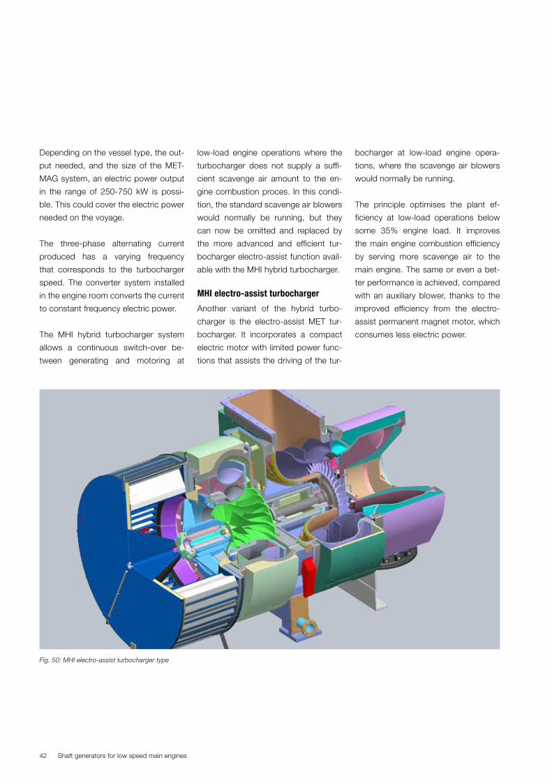
Shaft generators for low speed main engines42
Depending on the vessel type, the out-
put needed, and the size of the MET-
MAG system, an electric power output
in the range of 250-750 kW is possi-
ble. This could cover the electric power
needed on the voyage.
The three-phase alternating current
produced has a varying frequency
that corresponds to the turbocharger
speed. The converter system installed
in the engine room converts the current
to constant frequency electric power.
The MHI hybrid turbocharger system
allows a continuous switch-over be-
tween generating and motoring at
low-load engine operations where the
turbocharger does not supply a suffi-
cient scavenge air amount to the en-
gine combustion proces. In this condi-
tion, the standard scavenge air blowers
would normally be running, but they
can now be omitted and replaced by
the more advanced and efficient tur-
bocharger electro-assist function avail-
able with the MHI hybrid turbocharger.
MHI electro-assist turbocharger
Another variant of the hybrid turbo-
charger is the electro-assist MET tur-
bocharger. It incorporates a compact
electric motor with limited power func-
tions that assists the driving of the tur-
bocharger at low-load engine opera-
tions, where the scavenge air blowers
would normally be running.
The principle optimises the plant ef-
ficiency at low-load operations below
some 35% engine load. It improves
the main engine combustion efficiency
by serving more scavenge air to the
main engine. The same or even a bet-
ter performance is achieved, compared
with an auxiliary blower, thanks to the
improved efficiency from the electro-
assist permanent magnet motor, which
consumes less electric power.
Fig. 50: MHI electro-assist turbocharger type

Shaft generators for low speed main engines 43
The combined RENK shaft generator and waste heat recovery system
The engine-mounted BW III shaft
generator solution from RENK is also
available with a combined waste heat
by-pass power turbine solution to uti-
lise any excess heat available from the
exhaust gas. The power turbine is hy-
draulically coupled to the crankshaft
through the crankshaft gear already
available and used for the shaft genera-
tor mounted to the engine side.
These two systems are combined into
one unit offering the benefit of the two
without incurring the full first cost of
both, as the most expensive compo-
nent, the crankshaft gear, is shared.
The built-on shaft generator, which
serves all the electric power needed
on the voyage, will save running hours
and maintenance cost on the gensets,
and the power turbine feeds back the
mechanical power available from the
combustion processes, thereby reduc-
ing the main engine’s fuel consumption.
This system can benefit ships predomi-
nantly operated at load profiles higher
than 45% SMCR, for example contain-
er feeders.
Fig. 52: Sketch of turbo compound system/PTI without shaft generator type
Fig. 53: Schematic diagram of turbo compound system with and without a shaft generator
Fig. 51: RENK BW III turbo compound system

Shaft generators for low speed main engines44
Introduction
One of the main goals in the marine in-
dustry is to reduce the impact of CO2
emissions from ships in order to meet
stricter IMO greenhouse emission re-
quirements.
The folowing two CO2 indexes came
into force on 1 January 2013:
1. Energy efficiency design index
(EEDI) evaluates the engine and
vessel design and measures the
gCO2 eimission per ton per mile.
2. Energy efficient operational indica-
tor guides the operator in develop-
ing the best practice on board the
ship.
The goal is to design future ships with
stepwise reduced design index figures
in 2013, 2015, 2020 and 2025 which
corresponds to a 30% reduction of CO2
emissions and fuel consumption.
Based on the assumption that electric
power generated by a shaft generator
connected to the two-stroke main en-
gine is more efficiently made than elec-
tric power generated from gensets, the
IMO rules give a preference treatment
for PTO applications. In this respect,
a maximum of 2.5% of the installed
SMCR power can be deducted from
the main engine power used to calcu-
late the EEDI figure.
However, the power take in (PTI) sys-
tems using electric power produced by
gensets will influence the EEDI number
in upwards direction for applications
designed to increase the ship speed at
normal service conditions. For waste
heat recovery systems, where excess
electric power is available, it is possi-
ble to take advantage of the PTI using
excess electric power for propulsion
on the voyage without having an EEDI
penalty.
A BIMCO EEDI calculator is available to
explore further possibilities.
Summary
A wide range of shaft generators with
frequency control systems are available
for installation with an MAN B&W low
speed engine. Relative to the propel-
ler, a shaft generator application affects
the installed engine power and the shaft
generator application must also be in-
cluded in the torsion vibration calcula-
tions.
Fig. 54: EEDI calculation formula.
EEDI – Energy Efficiency Design Index
Пfј (ΣΡМЕ*CFME*SFCME) + PAE*CFAE*SFCAE + (Пfj*ΣPPTI - Σfeff*PAEeff)*CFAE*SFCAE - Σfeff*Peff*CFME*SFCME
PME Main engine 75% rated main power = 75% *PMCR(i) - PPTO(i)
PMCR Main engine Rated main engine power at MCR
PPTO Power Take-off Rated shaft generator at MCR
fi * Capacity *Vref*fw
EEDI =
PTI will penalise EEDI figures(higher EEDI number)
PTO will improve the EEDI figures(lower EEDI number)
PPTO
PMCR

Shaft generators for low speed main engines 45
However, despite the prolonged mean
time between overhauls, references
have shown that most MAN B&W low
speed engines are operated without a
shaft generator. This reflects the fact
that many shipowners and shipyards
still prefer the simple engine room lay-
out including electric power generated
by gensets.
On the other hand, when surplus ca-
pacity is available from the main engine,
a shaft generator is still a viable solution.
Advantages:
� PTO improves the EEDI figures
� Small space requirement
� Low investment cost (PTO/GCR)
� Low installation cost
� Low manhour cost for PTO mainte-
nance
� Low maintenance cost for PTO
� Reliable
� Long lifetime
� Low noise
The requirements to the engine govern-
ing system is typically not influenced by
a shaft generators with a normal elec-
tric capacity of less than 15% of the
SMCR power. However, for shaft gen-
erators with no frequency control sys-
tem, the stability of the engine speed
needs special consideration.
For shaft generators used in special
applications such as shuttle tanker
propulsion arrangements, the propeller
can be disconnected by a clutch, and
the main engine can be used to drive a
large alternator supplying electric pow-
er for the cargo pumps. In rare cases,
where an auxiliary loitering propulsion
system is used, the main engine is dis-
connected and the shaft generator is
used as an electric motor driving the
CP propeller with electric power gener-
ated by a number of gensets.
Gensets have improved their cost ef-
fectiveness thanks to low prices, HFO
operation and improved reliability.
Auxiliaryengines
EEDI = ∑Р × CF SFCCapacity × Speed
Shaft motor PPTI
Shaft power PS Main engine PME
PAE
Main engine Pumps (2.5% PME)
Cargo heat
Thrusters
Cargo pumps
Cargo gear
Reefers
Powerexcluded EEDI
Powerincluded EEDI
Ballast pumps
Boiler
Accommodation(250 kW)
Waste heatrecovery etc. PME
Shaftgenerator PPTI
Switch board
Fig. 55: EEDI parameters
Disadvantages:
� PTI will penalise EEDI figures
� No power production in harbour
� Higher load on main engine
� No long time parallel running ability
for PTO/GCR
� Reduced propeller efficiency at low
propulsion power for PTO/GCR
� More complex shaft arrangement
Abbreviations:
Gear constant ratio (GCR)
RENK constant ratio (RCF)
Constant frequency electrical (CFE)
Direct-mounted generator (DMG)
Shaft-mounted generator (SMG)
MAN Diesel & Turbo (MDT)
Low speed engine (2-stroke main en-
gine)
Power take-off (PTO)
Marine diesel oil (MDO)
Four-stroke diesel generator (genset)
Power take-in (PTI)
Propeller shaft clutch (PSC)
Power management system (PMS)
Pulse width modulated (PWM)

Shaft generators for low speed main engines46
References
BIMCO EEDI Calculator, link:
www.bimco.org/Products/EEDI.aspx
Waste Heat Recovery System,
MAN Diesel & Turbo, Copenhagen,
Denmark, Publication no.: 5510-0136,
Aug 2012
Image credits
http://www.mhi.co.jp/en/news/sto-
ry/1008261372.html

Shaft generators for low speed main engines 47

MAN Diesel & TurboTeglholmsgade 412450 Copenhagen SV, DenmarkPhone +45 33 85 11 00Fax +45 33 85 10 [email protected]
All data provided in this document is non-binding. This data serves informational purposes only and is especially not guaranteed in any way. Depending on the subsequent specific individual projects, the relevant data may be subject to changes and will be assessed and determined individually for each project. This will depend on the particular characteristics of each individual project, especially specific site and operational conditions. Copyright © MAN Diesel & Turbo. 5510-0003-02ppr Mdd 2015 Printed in Denmark