Embed Size (px)
Citation preview

Tutorium
CG2 LU

Overview
Shadow-Mapping
Bloom / Glow
Animation
Institute of Computer Graphics and Algorithms

Shadow Mapping
Peter Houska
Institute of Computer Graphics and Algorithms
Vienna University of Technology

Why Shadows?
Institute of Computer Graphics and Algorithms

Why Shadows?
Institute of Computer Graphics and Algorithms

Why Shadows?
Shadows ...
... make a scene look more three-dimensional
... emphasize the spatial relationship of
objects among each other
... tell us where the light comes from
... should really be there
Institute of Computer Graphics and Algorithms

Shadow Determination
Several techniques, e.g.
Shadow Mapping
Shadow Volumes
Let‟s take a closer look at Shadow Mapping
2 pass algorithm
fast on today's GPUs
relatively easy to implement
Institute of Computer Graphics and Algorithms

Shadow Mapping Overview
1st pass:
assume light source has a “view frustum” (like a camera)
render scene from light source‟s position
save depth values only
we end up with a shadow (depth-) map
2nd pass:render scene as usual
transform vertices to light space, too
for each fragment, compare its depth to previously stored depth (read it from shadow map)
zfragment > zfrom_shadow_map => fragment lies in shadow
fragment must be in light space!!!
Institute of Computer Graphics and Algorithms

Scene – “Meta” View
Institute of Computer Graphics and Algorithms
EyeLight
Source

Scene – Light Source View
Institute of Computer Graphics and Algorithms

Scene – Light Source View (Depth Only)
Institute of Computer Graphics and Algorithms
This is actually the shadow map!

Scene – Eye View
Institute of Computer Graphics and Algorithms

Shadowed Fragment
Institute of Computer Graphics and Algorithms
Eye View
“Meta“ View

Shadowed Fragment
Institute of Computer Graphics and Algorithms
“Meta“ View
fragment distance
to light sourcedistance
read
from
shadow
map
Eye View

Lit Fragment
Institute of Computer Graphics and Algorithms
“Meta“ View
Eye View

Lit Fragment
Institute of Computer Graphics and Algorithms
“Meta“ View
fragment distance
to light source
distance
read
from
shadow
map
Eye View

Involved Coordinate Systems
Institute of Computer Graphics and Algorithms
Eye
Space
Light
Space
World
Space
Object
Space

Vca
m
Involved Coordinate Systems
Institute of Computer Graphics and Algorithms
Eye
Light
World
Object
Object
World
Eye Light
M ... Model Matrix
Vcam ... Camera View Matrix
Vlight ... Light View Matrix

Transforming to World Space
Institute of Computer Graphics and Algorithms
Eye
Light
World
Object
Object
World
Eye Light

Transforming to Eye Space
Institute of Computer Graphics and Algorithms
Eye
Light
World
Object
rendering from the
eye„s point of view
Vca
m
Object
World
Eye Light

Transforming to Light Space
Institute of Computer Graphics and Algorithms
Eye
Light
World
Object
rendering from the
light source„s
point of view
Object
World
Eye Light

1st pass: Create Shadow Map
Institute of Computer Graphics and Algorithms
// create the texture we'll use for the shadowmapglGenTextures(1, &shadow_tex_ID);glBindTexture(GL_TEXTURE_2D, shadow_tex_ID);glTexImage2D (GL_TEXTURE_2D, 0, GL_DEPTH_COMPONENT24,
SM_width, SM_height, 0, GL_DEPTH_COMPONENT, GL_UNSIGNED_BYTE, NULL);
// attach texture to an FBOglGenFramebuffers(1, &shadow_FBO);glBindFramebuffer(GL_FRAMEBUFFER, shadow_FBO);glFramebufferTexture2D(GL_FRAMEBUFFER, GL_DEPTH_ATTACHMENT,
GL_TEXTURE_2D, shadow_tex_ID, 0);
glDrawBuffer(GL_NONE); // essential for depth-only FBOs!!!glReadBuffer(GL_NONE); // essential for depth-only FBOs!!!
// then, just before renderingglBindFramebuffer(GL_FRAMEBUFFER, shadow_FBO);

The “view” matrix must be set to Vlight
Note: No projection matrix used up to now!but light-”camera” involves another projection!
Turn off all effects when rendering to the shadow mapNo textures, lighting, etc.
1st pass: Create Shadow Map
Institute of Computer Graphics and Algorithms
Plig
ht
Object
World
Eye Light
Clip Space Light

Transform vertices to eye space and project
as usual
v' = Pcam * Vcam * M * v
2nd pass: Render from Eye‟s POV
Institute of Computer Graphics and Algorithms
Vca
mP
ca
m
Object
World
Eye Light
Clip Space Eye Clip Space Light

2nd pass: Render from Eye‟s POV
Also transform vertices to projected light space (= clip space
light)
basically the same steps as in the 1st pass:
vproj_lightspace = (Plight * Vlight) * M * v
vproj_lightspace is essentially the texture coordinate for accessing the
shadow map
Note:
the light source„s projection matrix may be different from the eye„s
projection matrix
Since OpenGL-FF does not store a separate model matrix, FF-
shadow mapping works like this (could still be used, even when
using shaders):
vproj_lightspace = (Plight * Vlight * Vcam-1) * Vcam * M * v
Institute of Computer Graphics and Algorithms
combined modelview matrix

2nd pass: Render from Eye‟s POV
One last issue...
Let vproj_lightspace =
After perspective division:
Institute of Computer Graphics and Algorithms
w
z
y
x
1
1
1
1
11
1
1
1
wz
wy
wx

So "standard" OpenGL projection matrix
generates xyz-clipspace coordinates in the
range [-1;+1] after perspective division
i.e. in normalized device coordinates
To access the shadow map, however, we
need coordinates in the range [0;+1]
Apply scaling and translation
2nd pass: Render from Eye‟s POV
Institute of Computer Graphics and Algorithms
[-1;+1]
[-0.5;+0.5]
[0;+1]
0.5
+0.5

Vca
mP
ca
m
2nd pass: Render from Eye‟s POV
Institute of Computer Graphics and Algorithms
Plig
ht
Object
World
Eye Light
Clip Space Eye
MS
Clip Space Light
MT
0.5
+0.5
SMtexcoord = (MT * MS * Plight * Vlight) * M * v
27
1000
02100
00210
00021
,
1000
21100
21010
21001
ST MM

Shadow Mapping – Vertex Shader
tex_mat = MT * MS * Plight * Vlight
Institute of Computer Graphics and Algorithms
#version 140uniform mat4 M; // model matrixuniform mat4 V_cam; // view matrix for the camerauniform mat4 P_cam; // projection matrix for the camerauniform mat4 tex_mat;
in vec4 vertex; // attribute passed by the applicationout vec4 SM_tex_coord; // pass on to the FS
void main(void) {// standard transformationgl_Position = P_cam * V_cam * M * vertex;
// shadow texture coords in projected light spaceSM_tex_coord = tex_mat * M * vertex;
}
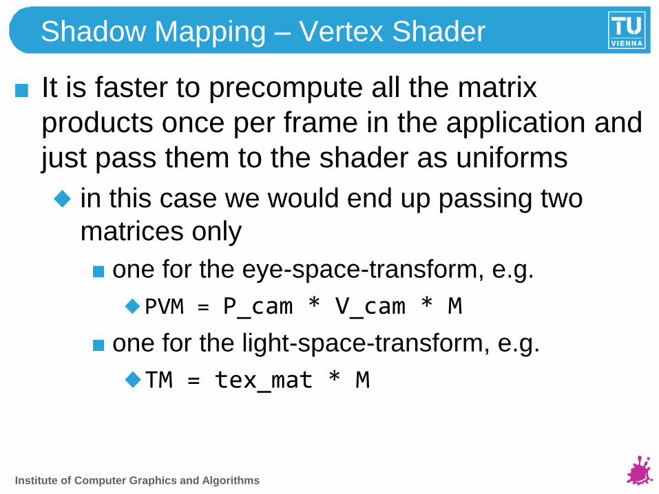
Shadow Mapping – Vertex Shader
It is faster to precompute all the matrix
products once per frame in the application and
just pass them to the shader as uniforms
in this case we would end up passing two
matrices only
one for the eye-space-transform, e.g.
PVM = P_cam * V_cam * M
one for the light-space-transform, e.g.
TM = tex_mat * M
Institute of Computer Graphics and Algorithms

Shadow Mapping – Fragment Shader
Institute of Computer Graphics and Algorithms
#version 140uniform sampler2D shadow_map; // shadow map is just a texture
in vec4 SM_tex_coord; // passed on from VSout vec4 fragment_color; // final fragment color
void main(void) {// perform perspective divisionvec3 tex_coords = SM_tex_coord.xyz/SM_tex_coord.w;
// read depth value from shadow mapfloat depth = texture(shadow_map, tex_coords.xy).r;
// perform depth comparisonfloat inShadow = (depth < tex_coords.z) ? 1.0 : 0.0;// do something with that value ...
}

Artifacts – Incorrect Self Shadowing
Institute of Computer Graphics and Algorithms
zEye > zLight incorrect self shadowing
zEye zLight

Artifacts – Incorrect Self Shadowing
When rendering to shadow map, either
add z-offset to polygons
render objects' backfaces only
Institute of Computer Graphics and Algorithms
glPolygonOffset(1.1, 4.0); // these values work well

Artifacts
Decrease ambient term
Filter shadow map lookup
Institute of Computer Graphics and Algorithms

Shadow Map Filtering and more
Enabling HW - percentage closer filtering (PCF):
GPU can do depth comparison:
Institute of Computer Graphics and Algorithms
glTexParameteri(GL_TEXTURE_2D, GL_TEXTURE_MIN_FILTER, GL_LINEAR);glTexParameteri(GL_TEXTURE_2D, GL_TEXTURE_MAG_FILTER, GL_LINEAR);
glTexParameteri(GL_TEXTURE_2D, GL_TEXTURE_COMPARE_MODE, GL_COMPARE_REF_TO_TEXTURE);
glTexParameteri(GL_TEXTURE_2D, GL_TEXTURE_COMPARE_FUNC, GL_LEQUAL);
GL_NEAREST GL_LINEAR

Fragment Shader for HW-assisted SM
Having set the previously mentioned texture parameters, we
can use another texture access function to read from the
shadow map:
Institute of Computer Graphics and Algorithms
#version 140
// tell GPU, that texture map is actually a shadow mapuniform sampler2DShadow shadow_map;
// just as before:in vec4 SM_tex_coord; // passed on from VSout vec4 fragment_color; // final fragment color
void main(void) {// perspective division, depth-comparison and PCF// is implicitly carried out by the GPUfloat shadow = textureProj(shadow_map, SM_tex_coord);// do something with that value ...
}

Shadow Mapping and Projective Texturing
Once shadow mapping works, projective texturing can be implemented easily
Same transformation steps necessary to access the "texture-to-project"
the only difference:
shadow map stores depth information which is fetched, but only used for comparing distances to the corresponding light source
projected texture stores the color value itself, so a simple texture lookup determines the fragment's color
is actually easier than shadow mapping!
Institute of Computer Graphics and Algorithms

Projective Texturing – Short Summary
Render scene from the eye's point of view ...
... and also transform the surface positions to projector space (for SM this would be light space)
i.e. determine, where the world space surface point pierces the projector's viewplane
"forward-projection" (scene-to-viewplane)
the projector's viewplane (a texture) determines the fragment's color
Institute of Computer Graphics and Algorithms
view plane
projector

Projective Texturing – Thinking Differently
Another way to figure the mapping to "projector space":
to determine, where the world space surface point pierces the projector's viewplane is equivalent to the following question:
where does a point on the projector's viewplane intersect the scene along the projector's viewing rays (~raycasting)
"backward-projection" (viewplane-to-scene)
maybe more natural to think about projective texturing this "inverse" way...
Institute of Computer Graphics and Algorithms
view plane
projector

Projective Texturing - Example
Institute of Computer Graphics and Algorithms
http://developer.nvidia.com/object/Projective_Texture_Mapping.html

References
www.opengl.org/registry
http://www.opengl.org/registry/doc/glspec31undep.20090528.pdf
http://www.opengl.org/registry/doc/GLSLangSpec.Full.1.40.07.pdf
http://developer.nvidia.com/object/Projective_Texture_Mapping.html
http://developer.nvidia.com/object/hwshadowmap_paper.html
These slides are partly based on a fantastic shadow mapping tutorial
written by Martin Knecht
Institute of Computer Graphics and Algorithms

Bloom Effect
Glow Effect
Reinhold Preiner
Institute of Computer Graphics and Algorithms
Vienna University of Technology

Institute of Computer Graphics and Algorithms
Bloom Effect
Screen-space post effect
Simulates imaging artifact of lenses
Very bright light produces light bleeding
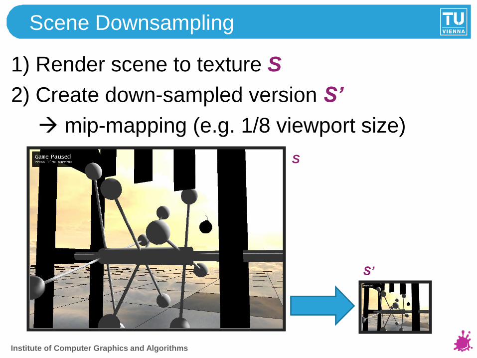
Scene Downsampling
1) Render scene to texture S
2) Create down-sampled version S’
mip-mapping (e.g. 1/8 viewport size)
Institute of Computer Graphics and Algorithms
S
S’

Bright Pass
• Find some bright-pass RGB threshold T (e.g.
0.8) – could also continuously change over
frames
• Create Bright-pass texture B’ from S’,
leaving only pixels with RGB > T
• Different operators
Institute of Computer Graphics and Algorithms

LDR Bright Pass
• B‟ = max( S‟ – T, 0 )
S’ B’
• Other operators possible:
B‟ = S‟ > T ? S‟ : 0; (heavy bloom)
Institute of Computer Graphics and Algorithms

Blur Bright-Pass Texture
• 2D Gauss-Blur Can be decomposed into
two 1D passes (x and y)
• Try different kernel sizes! (3, 5, 7, …)
B’ G’
• Blur: down-sampled texture sufficient!Institute of Computer Graphics and Algorithms

Final (Weighted) Blending
+
=
Institute of Computer Graphics and Algorithms

With and without Bloom
Institute of Computer Graphics and Algorithms
Bloom Effect
• Don‟t exaggerate it!
• Play with parameters
• Colored bloom vs. white bloom
• HDR Bloom
• Bloom on HDR valus (rgb > 0)
• Threshold connected with iris effect and
tonemapping possible
• Non-linear bright-pass segmentation models
Institute of Computer Graphics and Algorithms

Bloom Effect - References
• GL: prideout.net/archive/bloom/index.php
• HDR-Bloom: DirectX10 HDRLighting sample
Institute of Computer Graphics and Algorithms

Institute of Computer Graphics and Algorithms
Glow Effect
Screen-space post effect
Simulates glowing parts of objects (halos)
Implementation similar to Bloom
Surface texture based
Image: Tron (GPU Gems 1)

Institute of Computer Graphics and Algorithms
Glow – Object Texturing
Each object provides 4 channel textures:
RGB: diffuse color
Alpha: glow intensity (0 … no glow, 1 … full
glow)
If alpha used for transparency 2 textures
Image: GPU Gems 1

Glow Effect Pipeline
(a) Render scene to texture (FBOs)
(b) Create glow source texture from (a)
GlowSource = RGB * A
(c) Blur glow source texture
(d) Blend (c) with (a) Image: GPU Gems 1
Institute of Computer Graphics and Algorithms

Institute of Computer Graphics and Algorithms
Afterglow
Also blend the glow texture from the previous
frame over the current one.
Creates an afterglow when moving object or
camera over several frames.

Glow Effect - References
RTF GPU Gems!
Brief and good description on GPU Gems 1,
Chapter 21.
http.developer.nvidia.com/GPUGems/gpugems_ch21.html
Institute of Computer Graphics and Algorithms

Institute of Computer Graphics and Algorithms
Screen-space per-pixel processing
FBOs
Draw a fullscreen quad (4 vertices + texcoords):[(0,0), (1,0), (1,1), (0,1)]
Vertex shader: pass vertices to NDCoutPos = inPos * 2 – 1
Normally no Depth Buffering
Fragment shader: implement the pixel color tansformation

Institute of Computer Graphics and Algorithms
Gauss-Blur HowTo
First blur horizontally, then vertically
Per pixel: weighted sum of neighbors.
5x5-kernel weights:
(0.061, 0.242, 0.383, 0.242, 0.061)
Institute of Computer Graphics and Algorithms
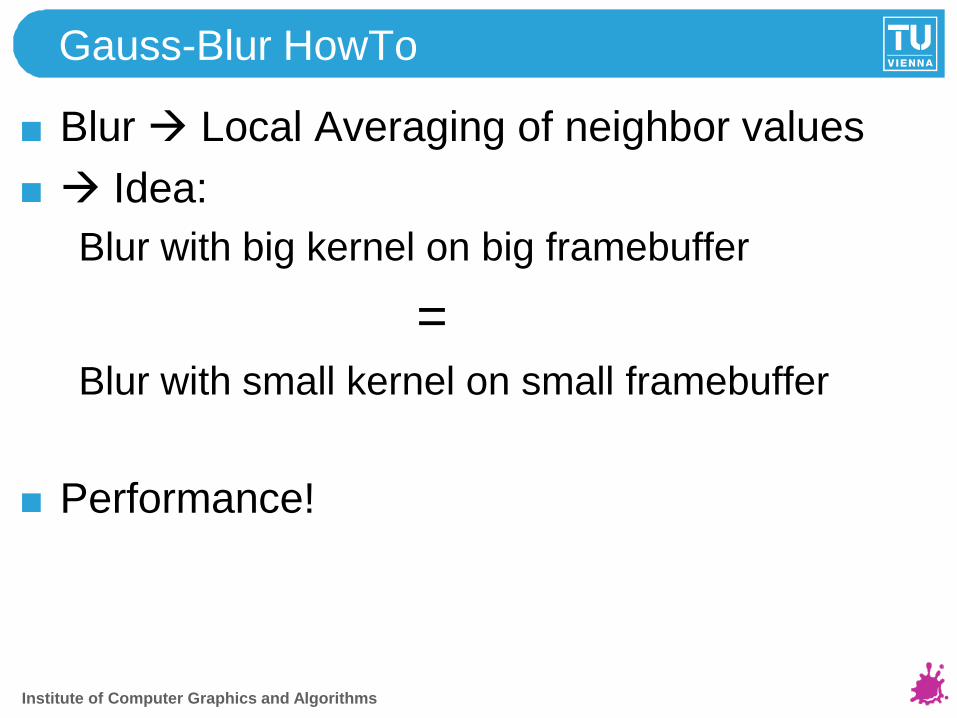
Gauss-Blur HowTo
Blur Local Averaging of neighbor values
Idea:
Blur with big kernel on big framebuffer
=Blur with small kernel on small framebuffer
Performance!

Character Animation Basics
Galina Paskaleva
Institute of Computer Graphics and Algorithms
Vienna University of Technology

Key frames
Key frame
“snapshot” of the character at some moment
Key frame based animation
Which parameter is interpolated ?
Vertex animation
All vertices are keyed (~“stored”), i.e. each key
frame consist of all the vertices in the model
Skeletal animation
Only bones are keyed
60Institute of Computer Graphics and Algorithms

Vertex Animation
3D artist models “key” (important) frames only
Key frames are important poses
Character may be in particular state
standing, running, firing, dying etc.
Store several key frames for each state
usually up to 15 key frames / sec
if more are needed
use non-linear interpolation to reduce their
number
consider another animation technique
61Institute of Computer Graphics and Algorithms

Vertex Animation
Example:
Key frames for character in “Running” state
62Institute of Computer Graphics and Algorithms

Vertex Animation
Interpolate poses in between
Always 2 key frames involved
Several types of interpolation
linear, quadratic, ...
Linear interpolation fast, usually good enough
Blending factor w
blendedPos =
(1-w)*keyFrameA – w*keyFrameB
63Institute of Computer Graphics and Algorithms

Vertex Animation
Linearly interpolated key frames:
64Institute of Computer Graphics and Algorithms

Vertex Animation
All key frames must have
Same number of vertices
Same vertex connectivity
65Institute of Computer Graphics and Algorithms
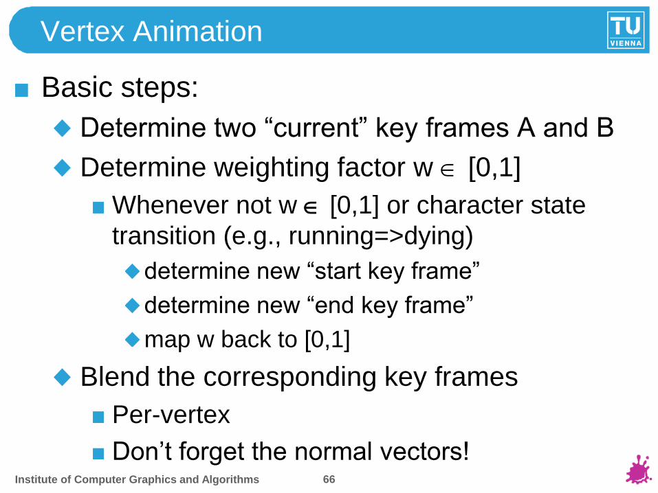
Vertex Animation
Basic steps:
Determine two “current” key frames A and B
Determine weighting factor w [0,1]
Whenever not w [0,1] or character state
transition (e.g., running=>dying)
determine new “start key frame”
determine new “end key frame”
map w back to [0,1]
Blend the corresponding key frames
Per-vertex
Don‟t forget the normal vectors!66Institute of Computer Graphics and Algorithms

Vertex Animation
Vertex Shader:
67
uniform float weightingFact;
void main(){
// use built-in “vertex attribute-slots” to pass // necessary data// alternatively, pass user-defined vertex attributesvec4 keyFrameA_vert = gl_Vertex;vec3 keyFrameA_norm = gl_Normal;
vec4 keyFrameB_vert = gl_MultiTexCoord6;vec3 keyFrameB_norm = gl_MultiTexCoord7.xyz;
...
Institute of Computer Graphics and Algorithms

Vertex Animation
Vertex Shader:
68
...// linear interpolation:// blendedPos_vert = // (1.0 – weightingFact) * keyFrameA_vert +// weightingFact * keyFrameB_vertvec4 blendedPos_vert = mix(keyFrameA_vert,
keyFrameB_vert,weightingFact);
vec3 blendedPos_norm = mix(keyFrameA_norm, keyFrameB_norm,weightingFact);
...
Institute of Computer Graphics and Algorithms

Vertex Animation
Vertex Shader:
69
...// normalize blended normal and maybe// perform some light computation with the // normal (here, the normal is still in object// space!)vec3 normal = normalize(blendedPos_norm);
// pass texture coordinates as alwaysgl_TexCoord[0] = gl_MultiTexCoord0;
// transform blended vertex to homogeneous clip spacegl_Position =
gl_ModelViewProjectionMatrix*blendedPos_vert; }
Institute of Computer Graphics and Algorithms
Vertex Animation
Advantages
Simple to implement
Disadvantages
High storage requirements
No dynamic “arbitrary” poses
70Institute of Computer Graphics and Algorithms

Skeletal Animation
Character model consists of
Single default pose
A polygonal mesh (made of vertices)
...the “skin“
Several “bones“
Matrices that translate and rotate default
pose„s vertices
Define coarse character structure
Like a stick-figure
Institute of Computer Graphics and Algorithms

Skeletal Animation
Real life analogy:
As bones move, skin moves appropriately
But: influence of bones locally bounded
E.g., moving left arm does not affect right leg
Bone set
Matrices that actually influence a vertex
Typically contains <= 4 matrices
Each matrix Mi has associated weight wi
boneSetw
ii
i
ww 1,0
Institute of Computer Graphics and Algorithms

Skeletal Animation
Matrix-weight determines how much it
influences a vertex„s position
bone polygonal mesh
= “skin“
At this vertex, 3 matrices in bone set with corresponding weights:
60% forearm matrix
30% elbow matrix
10% upper arm matrix
vertex
Institute of Computer Graphics and Algorithms

Skeletal Animation
Basic steps during rendering:
Transform each vertex by every matrix in its
bone set
Scale each transformed vertex by the
associated matrix weighting factor
Sum results => skinned vertex position
Special case:
For default pose all the bone set„s matrices
are identity matrices
Institute of Computer Graphics and Algorithms

Skeletal Animation - Normals
How to treat normals?
Basically the same steps as for vertices
But: transform normals by the inverse
transpose matrix tM-1 rather than the matrix M
itself (see [2] for details)
If matrices contain rotations and translations
only, M = tM-1
Normalize the blended normal
Institute of Computer Graphics and Algorithms

Skeletal Animation
Advantages
Storage quite efficient
Only one mesh (+ several matrices)
Huge savings for high-poly models
Most probably still “only a few” bones
Create novel poses dynamically!
Supports blending several “animation-states”
Running + Firing + Look upwards + ...
Rag doll physics when killed by a shot etc.
Inverse Kinematics and Constraints can produce
quite realistic results
76Institute of Computer Graphics and Algorithms

Skeletal Animation
Disadvantages
Matrices hierarchically linked!
each matrix needs to be multiplied by its
predecessors in the correct order before applying it
to the vertex
for each bone (matrix) in the bone set the vertex has
to be transformed into the bone space before
applying the influence of said bone on the vertex
vertex blending occurs in object space, so the
reverse transformation is also necessary
animation needs to be developed in a 3D-modeling
software (Maya, 3ds Max, Blender, etc.)
7777Institute of Computer Graphics and Algorithms
Vertex Animation with Morph Targets
Morph Target
a „snapshot“ of a character not at a particular time
but at a particular pose
applied when
dynamic „arbitrary“ poses are needed
animation is too fine-grained for the bone + skin
approach (i.e. facial expressions)
Animation with Morph Targets
Which parameters are interpolated?
Vertex animation: for each morph target the
difference vector per vertex is stored
7878Institute of Computer Graphics and Algorithms

Vertex Animation with Morph Targets
a neutral model N and k ≥ 1 different poses P1 … Pk
in the preprocessing stage the difference models are
computed:
Di = Pi – N, i = 1 … k.
7979Institute of Computer Graphics and Algorithms

Vertex Animation with Morph Targets
8080
a neutral model N and k ≥ 1 different poses P1 … Pk
in the preprocessing stage the difference models are
computed:
Di = Pi – N, i = 1 … k.
Institute of Computer Graphics and Algorithms

Vertex Animation with Morph Targets
8181
a neutral model N and k ≥ 1 different poses D1 … Dk
to obtain a morphed model compute:
M = N + ∑ wiDi.k
i = 1
Institute of Computer Graphics and Algorithms

Vertex Animation with Morph Targets
Advantages
fine-grained animation does not result in
complex implementation
the weights wi can be:
≤ 0 (inverted pose) or
≥ 1 (exaggerated pose)
Disadvantages
the neutral model N and the different poses P1 …
Pk need :
the same number of vertices
the same vertex connectivity8282Institute of Computer Graphics and Algorithms

Pose Space Deformation
Example (see [7]):
8383
Pose Space Deformation Skeleton Space Deformation
Institute of Computer Graphics and Algorithms

Pose Space Deformation
Combines Skeletal Animation and Morph
Targets (each is a dimension in the Pose
Space)
Basic steps:
apply skeletal animation in skeleton space
for each affected vertex compute deviation
from relevant poses in pose space (a falloff
ensures that only the most „relevant“ poses
are considered)
interpolate deviation and apply to vertex
For more information see [7].8484Institute of Computer Graphics and Algorithms

References and Further Reading[1] The CG Tutorial: The Definitive Guide to Programmable
Real-Time Graphics
http://http.developer.nvidia.com/CgTutorial/
cg_tutorial_chapter06.html
[2] http://www.glprogramming.com/red/appendixf.html
[3] http://www.darwin3d.com/conf/igdn0398/index.htm
[4] http://tfc.duke.free.fr/old/models/md2.htm
[5] OpenGL Shading Language, Randi J. Rost, 3rd Edition,
Chapter 16 Animation
[6] http://http.developer.nvidia.com/GPUGems/
gpugems_ch04.html
[7] Lewis, J.P., Matt Cordner, Nickson Fong, „Pose Space
Deformation: A Unified Approach to Shape Interpolation and
Skeleton-Driven Deformation“, Computer Graphics (SIGGRAPH
2000 Proceedings), pp. 165-172,July 2000.85Institute of Computer Graphics and Algorithms

Further Credits / Thanks
8686
Peter Houska
Martin Knecht
Institute of Computer Graphics and Algorithms


![Alias-Free Shadow Maps - NVIDIA Research Homepageresearch.nvidia.com/.../files/pubs/2004-06_Alias-Free-Shadow-Maps/... · Alias-Free Shadow Maps ... I.3.7 [Computer Graphics]: Three-Dimensional](https://img.pdfslide.us/doc/110x75/5aa5dbc37f8b9ae7438e123a/alias-free-shadow-maps-nvidia-research-shadow-maps-i37-computer-graphics.jpg)