Embed Size (px)
Citation preview
Shadow Generation of Linear Light Source without 3D Reconstruction
JEN-HUI CHUANG and JAU-HONG KAO Department of Computer Science National Chiao Tung University
No. 1001, Ta Hsueh Rd., Hsinchu City TAIWAN
Abstract: - This paper presents a novel image-based approach to generating object shadows. Previous approaches of shadow generation are usually based on 3D geometry. In this paper, we present a method of deriving accurate shadows of a 3D object using multiple images without 3D reconstruction. For each view of the scene, the object shadows due to a linear light source connecting the two view points can be generated. The shadow generation is accomplished by identifying shadow region in an image with respect to some reference points on a base plane. The proposed approach uses view-invariant cross ratio and some geometric properties associated with perspective projection. It is also extended to generate shadows for more general scenes where multiple objects and multiple projection planes on which object shadows are to be cast are involved. Experiments show that the shadows generated for both real and synthetic scenes are satisfactory and the computation is efficient. Key-Words: - shadow generation, linear light source, image-based, cross ratio 1 Introduction Shadows increase the perception of image realism, and can also enhance users’ spatial awareness. Several shading and shadowing algorithms, which are based on 3D information of the scene, have been proposed for directional lights, point lights, spot lights, and so on [1][2]. There are two general purpose shadow algorithms for interactive applications. The approaches based on shadow volume are object space methods and the ones based on shadow map are sampling based that works with depth images of the scene [13]. Among them, illumination from linear and area light sources generates penumbras along shadow boundaries which notably enhance the photo-realism of an image. For the illumination due to a linear light source, sampling methods, which represents the light source with a series of point light sources, are often used [10]. This is because a shadowing algorithm for a point light source is simple. However, if the point samples are too sparse, serious aliasing artifacts will occur. On the other hand, for very dense samples, the computation cost will become excessive. Instead of sampling, another type of shadowing algorithms, e.g., the ones use light clipping process, determines the illumination of a point on the object surface by identifying the portions of each linear light source visible from that point. However, when many complex objects cast shadows onto rugged object surfaces, the cost for the light clipping process is extremely high. To reduce the cost, Bao et al. [2]
proposed an extension of the BSP tree-based shadowing algorithm which is originally developed for point light sources [3] [9]. In [7], an algorithm which can precisely generate shadows due to a linear light source for complex (curved) objects other than planar polygons is introduced. The algorithm computes the illumination of each point in the penumbra by using an integral function to evaluate the diffuse and specular effects simultaneously. In order to reduce the higher cost due to more complex object shapes, only the objects occupying the subdivisions and intersecting the light triangle are considered. In [8], a ray-oriented buffer is proposed to improve the rendering performance by reducing the computation time for the selection of candidate polygons. The authors of [12] proposed a soft shadow algorithm to produce penumbra regions for linear light sources. It is not an exact method and will produce artifacts if the light source is severely undersampled. Another model-based approaches are based on radiosity methods, which have to address the problem of large computation cost [15][16]. On the other hand, geometries between 2D image features are also used to derive 3D information in some approaches, such as [11]. In that method, a special setup of the scene and some assumptions speed up the computation of the camera calibration. However, these simplified calibration model are often sensitive to the quality of imaging device and depend on the sophisticate image processing techniques. In addition, there has been some work on
Proceedings of the 10th WSEAS International Conference on COMPUTERS, Vouliagmeni, Athens, Greece, July 13-15, 2006 (pp169-174)
generating shadows from image-based scene representations [14]. Previous works such as those in [1-4, 7-16] are generally based on 3D geometry. Relevant 3D data required in the shadow computation includes the object model, the location of light sources and the surfaces on which the object shadows are to be cast. In this paper, an algorithm which obtains realistic shadowing effects purely using 2D information is proposed. The system neither utilizes calibrated cameras nor performs 3D reconstruction of the scene. Similar to the sampling methods, we use a set of point samples to approximate a linear light source. In the next section, an approach to generate shadow due to a point light source developed in [6] is briefly reviewed. In Section 3, the approach is extended for generating shadows due to a linear light source. Experimental results and summary are given in Sections 4 and 5, respectively.
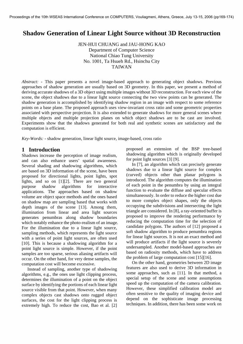
(a) (b)
Fig. 1 (a) A wireframe image rendered at viewpoint V1. (b) A wireframe image rendered at viewpoint V2.
2 Shadows of Point Light Sources In this section, we briefly review the approach developed in [6] for shadow generation of due to a point light source using 2D image data. The 2D data are extracted, possibly interactively, from pictures taken by some unknown cameras. Given two images I and II, the approach assumes that the object region can be identified in I, and the base plane, where the object’s shadow is to be cast upon, can be identified in both I and II. Moreover, at least five reference points on the base plane can be identified and any three of them must not be collinear in the images. The 3D information of the base plane, e.g., the position in the scene, is not required in the process.
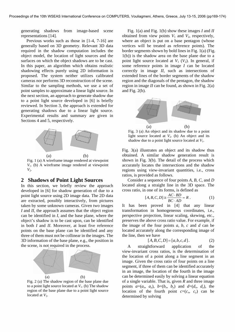
(a) (b)
Fig. 2 (a) The shadow region of the base plane due to a point light source located at V1. (b) The shadow region of the base plane due to a point light source located at V2.
Fig. 1(a) and Fig. 1(b) show these images I and II obtained from view points V1 and V2, respectively, where an object is put on a base pentagon (whose vertices will be treated as reference points). The border segments shown by bold lines in Fig. 1(a) (Fig. 1(b)) is the shadow area on the base plane due to a point light source located at V1 (V2). In general, if some reference points in image I can be located correctly in image II, such as intersections of extended lines of the border segments of the shadow region and the diagonals of the pentagon, the shadow region in image II can be found, as shown in Fig. 2(a) and Fig. 2(b).
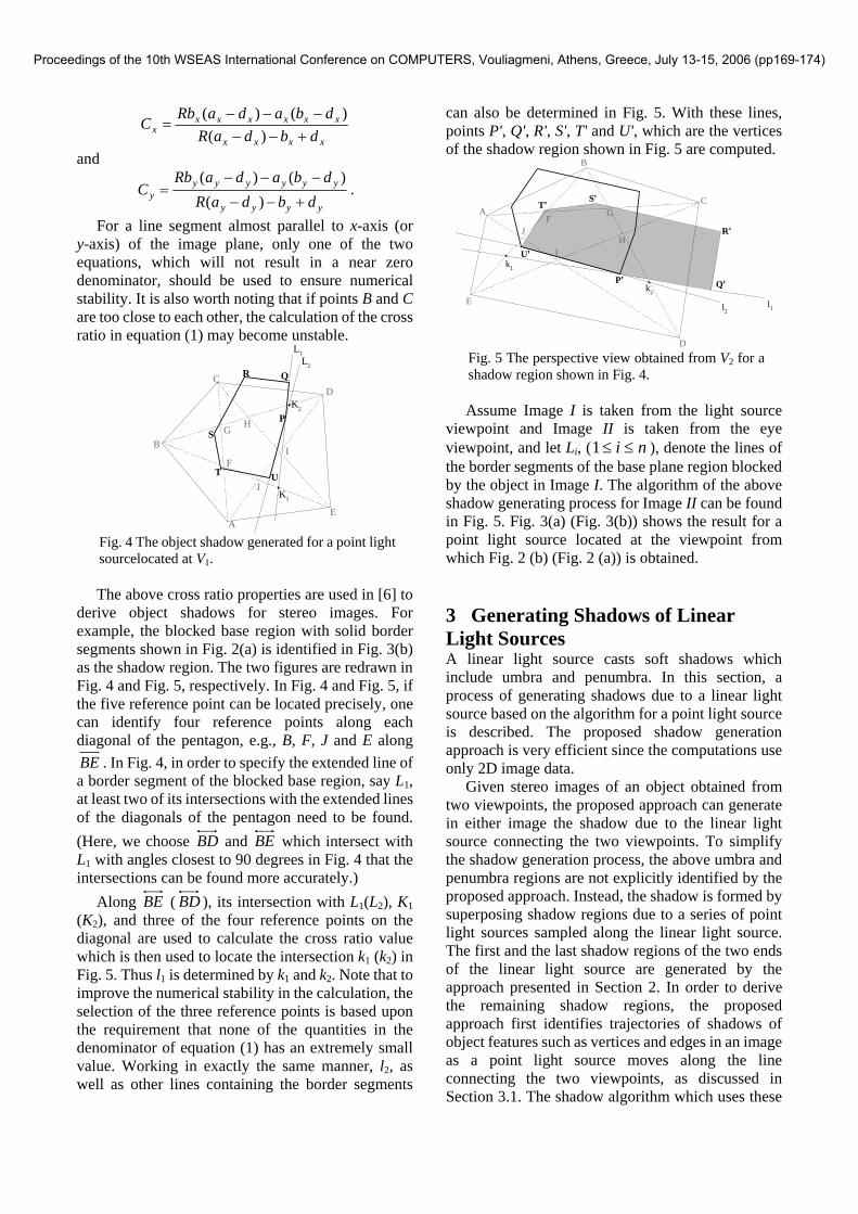
(a) (b)
Fig. 3 (a) An object and its shadow due to a point light source located at V2. (b) An object and its shadow due to a point light source located at V1.
Fig. 3(a) illustrates an object and its shadow thus obtained. A similar shadow generation result is shown in Fig. 3(b). The detail of the process which accurately locates the intersections and the shadow regions using view-invariant quantities, i.e., cross ratios, is provided as follows. Consider a sequence of four points A, B, C, and D located along a straight line in the 3D space. The cross ratio, in one of its forms, is defined as
RADBCBDACDCBA =⋅⋅
≅],,,[ . (1)
It has been proved in [4] that any linear transformation in homogeneous coordinates, i.e., perspective projection, linear scaling, skewing, etc., preserves the above cross ratio value. For example, if the image of the four points a, b, c and d can be located accurately along the corresponding image of the line, then we have
],,,[],,,[ dcbaDCBA = . (2) A straightforward application of the view-invariant cross ratios, is the determination of the location of a point along a line segment in an image. Given the cross ratio of four points on a line segment, if three of them can be identified accurately in an image, the location of the fourth in the image can be determined easily by solving a linear equation of a single variable. That is, given R and three image points a=(ax, ay), b=(bx, by) and d=(dx, dy), the location of the fourth point c=(cx, cy) can be determined by solving
Proceedings of the 10th WSEAS International Conference on COMPUTERS, Vouliagmeni, Athens, Greece, July 13-15, 2006 (pp169-174)
xxxx
xxxxxxx dbdaR
dbadaRbC
+−−−−−
=)(
)()(
and
yyyy
yyyyyyy dbdaR
dbadaRbC
+−−
−−−=
)()()(
.
For a line segment almost parallel to x-axis (or y-axis) of the image plane, only one of the two equations, which will not result in a near zero denominator, should be used to ensure numerical stability. It is also worth noting that if points B and C are too close to each other, the calculation of the cross ratio in equation (1) may become unstable.
L1L2
C
B
AE
D
F
G H
J
S
T U
P
QR
K1
I
K2
Fig. 4 The object shadow generated for a point light sourcelocated at V1.
The above cross ratio properties are used in [6] to derive object shadows for stereo images. For example, the blocked base region with solid border segments shown in Fig. 2(a) is identified in Fig. 3(b) as the shadow region. The two figures are redrawn in Fig. 4 and Fig. 5, respectively. In Fig. 4 and Fig. 5, if the five reference point can be located precisely, one can identify four reference points along each diagonal of the pentagon, e.g., B, F, J and E along BE . In Fig. 4, in order to specify the extended line of a border segment of the blocked base region, say L1, at least two of its intersections with the extended lines of the diagonals of the pentagon need to be found. (Here, we choose BD and BE which intersect with L1 with angles closest to 90 degrees in Fig. 4 that the intersections can be found more accurately.) Along BE ( BD ), its intersection with L1(L2), K1 (K2), and three of the four reference points on the diagonal are used to calculate the cross ratio value which is then used to locate the intersection k1 (k2) in Fig. 5. Thus l1 is determined by k1 and k2. Note that to improve the numerical stability in the calculation, the selection of the three reference points is based upon the requirement that none of the quantities in the denominator of equation (1) has an extremely small value. Working in exactly the same manner, l2, as well as other lines containing the border segments
can also be determined in Fig. 5. With these lines, points P', Q', R', S', T' and U', which are the vertices of the shadow region shown in Fig. 5 are computed.
A
B
C
D
E
P’ Q’
R’
S’T’
U’
F G
HI
J
k1
k2
l1l2
Fig. 5 The perspective view obtained from V2 for a shadow region shown in Fig. 4.
Assume Image I is taken from the light source viewpoint and Image II is taken from the eye viewpoint, and let Li, ( ni ≤≤1 ), denote the lines of the border segments of the base plane region blocked by the object in Image I. The algorithm of the above shadow generating process for Image II can be found in Fig. 5. Fig. 3(a) (Fig. 3(b)) shows the result for a point light source located at the viewpoint from which Fig. 2 (b) (Fig. 2 (a)) is obtained. 3 Generating Shadows of Linear Light Sources A linear light source casts soft shadows which include umbra and penumbra. In this section, a process of generating shadows due to a linear light source based on the algorithm for a point light source is described. The proposed shadow generation approach is very efficient since the computations use only 2D image data. Given stereo images of an object obtained from two viewpoints, the proposed approach can generate in either image the shadow due to the linear light source connecting the two viewpoints. To simplify the shadow generation process, the above umbra and penumbra regions are not explicitly identified by the proposed approach. Instead, the shadow is formed by superposing shadow regions due to a series of point light sources sampled along the linear light source. The first and the last shadow regions of the two ends of the linear light source are generated by the approach presented in Section 2. In order to derive the remaining shadow regions, the proposed approach first identifies trajectories of shadows of object features such as vertices and edges in an image as a point light source moves along the line connecting the two viewpoints, as discussed in Section 3.1. The shadow algorithm which uses these
Proceedings of the 10th WSEAS International Conference on COMPUTERS, Vouliagmeni, Athens, Greece, July 13-15, 2006 (pp169-174)
feature trajectories to derive the object shadow due to a linear light source is provided in Section 3.2. 3.1 Trajectories of shadows of object
features due to point light sources moving along a straight line
In this subsection, the point light source algorithm described in the previous section is extended to locate trajectories of shadows of object features due to point light sources moving along a straight line in an image. Object shadows due to a linear light source can then be obtained from these object features. The object image obtained from viewpoint V1 which is shown in Fig. 2(a) is redrawn here in Fig. 6 to explain this trajectory locating process for object features. Assume that X, , is the image of an object vertex obtained at viewpoint V1, and X', , is the shadow of X due to a point light source located at viewpoint V2. The correspondence between Xs and X's can be established by the framework developed in
}H G, F, E, D, C, B, A,{∈X
}H' ,G' ,F' ,E' ,D' ,C' ,B' ,A'{'∈X
[5] wherein the correspondence between base vertices are determined first. It is easy to see that in image space the shadows of object features due to a series of point light sources lying on the extended line of 21VV , have the following two geometric properties:
i. For a vertex X of an object, its shadows lie on the straight line 'XX . (For example, E, E' and E'' are collinear as shown in Fig. 6.)
ii. The extended lines of the shadows of each object edge are either intersected at the same point or parallel to each other.
For each X in Fig. 6, the straight line described in (i) and the intersection point of the extended lines in (ii) can be obtained easily by identifying X' with the approach presented in Section 2. Note that though the parallel case described in (ii) occurs under special 3D configuration, it applies exactly the same process in image space as that for intersecting cases. Therefore, given a vertex (or/and an edge) of an object shadow due to a point light source located on 21VV , one can derive the remaining vertices and edges of the shadow by intersecting corresponding linear trajectories of object vertices described in (i) and the extended lines of object edges given in (ii). An algorithm to derive shadow due to a linear light source using these features will be presented next.
A
C
B
D
E
FG
H
B’C’
E’H”
B”
C”
E”
Fig. 6 Edge and vertex features of an object in image space.
3.2 The Generation of an Object Shadow
due to a linear light source In this subsection, a shadow generation algorithm which uses shadows of object features discussed in the previous subsection to generate object shadows due to a linear light source is given. Consider
}'{'' BBB ∈ in Fig. 6 which is the shadow of object
vertex B due to a point light source lying on 21VV . According to (ii), one can easily find the straight line
'''' CB passing through B'' and parallel to BC and ''CB . It intersects 'CC at C'', which is the shadow of
C. Similarly, for each X, , one can obtain X'', where
}H G, F, E, D, C, B, A,{∈X
}'H' ,'G' ,'F' ,'E' ,'D' ,'C' ,'B' ,'A'{'' ∈X . (Note that in this example A'', D'', F'' and G'' coincide with A, D, F and G, respectively, since they are actually the base points.) With this shadow boundary identifying process, object shadows due to a series of point light sources located along a straight line can also be generated in an image. Two images are sufficient to generate the shadow if all of the projections of the utilized vertices on object boundary can be identified in both of them. In general, it is not always true that all the needed object vertices can be identified in two images. In this case, we will need additional image(s) to ensure that these vertices can be seen from at least two view points. In fact, we only need to consider vertices which will become vertices of the shadow boundary. For instance, B in Fig. 6 needs correspondence and F does not need however. On the other hand, if an object vertex has been identified as a base point, possibly interactively, only one image is sufficient for that vertex. The developed approach can then be used to obtain shadows of the object with minor modifications, i.e., by separating vertices into groups
Proceedings of the 10th WSEAS International Conference on COMPUTERS, Vouliagmeni, Athens, Greece, July 13-15, 2006 (pp169-174)
that utilize different sets of images and generating all the needed trajectories of object features. In order to derive soft shadows, an intensity buffer is used to calculate the illuminations of all image points. Depending on the density of the virtual point light sources sampled between the two view points, there is a trade-off between the quality of the synthesized image and the computation time. 4 Experimental Results This section illustrates experimental results for both synthetic and real images. In complicated scenes, shadows of an object are often projected onto multiple planes. The algorithm developed in previous sections can deal with such scenes if at least five reference points are identifiable in two or more images for each projection plane. In general, shadow regions may go beyond the boundary of a projection plane. In that case, the boundary of the projection plane needs to be specified in the image. One may need to clip certain portions of the derived shadow regions which are outside a projection plane with a finite size or blocked by other polygon objects (or projection planes). Although in our implementation, the shapes of projection planes and the geometric relationships among them, e.g., the visibility with respect to different view points, are established manually in advance, the proposed approach can be enhanced by importing a fraction of 3D information or by applying other algorithms such as the BSP tree. Fig. 7 and Fig. 8 illustrate shadow generation examples of scenes with multiple projection planes. In Fig. 7, a box is placed on the base plane hung in the air. Shadows are cast upon the base plane and the ground plane underneath the base plane, with five reference points also shown for both planes. Note that shadows of the base plane are also cast upon the ground plane. The pyramid in Fig. 8, on the other hand, casts shadows upon the two wall planes and the ground plane. The developed algorithms are implemented with Microsoft Visual Basic 6.0 running on a Pentium II PC. All images are rendered in 32-bit RGBA color mode and the sizes are 800 by 600 pixels. The computation time for shadow region generation is much less than that for updating the intensity buffers. For example, Fig. 7 and Fig. 8 take 0.48 and 0.46 seconds for shadow region generation and 1.07 and 1.44 seconds for updating the intensity buffers, respectively. The time spends for updating the intensity buffers is roughly proportional to the amount of accesses of the intensity buffers. Though our implementation does not use special instruction
for fast memory access provided by modern CPU, we believe the use of this support of hardware can extremely improve the overall performance of the proposed approach.
(a) (b)
(c) (d)
Fig. 7 (a) and (b): Two images of an object placed on a base plane. Reference points on both planes are marked with black color. (c) and (d): Shadow generation results of (a) and (b), respectively.
(a) (b)
(c) (d)
Fig. 8 Another shadow generation example for multiple projection planes using 20 virtual point light sources.
(a) (b)
(c) (d) Fig. 9 A real image example. (a) and (b) are source images. Shadows generated with 30 virtual point light sources are blended in (c) and (d).
Proceedings of the 10th WSEAS International Conference on COMPUTERS, Vouliagmeni, Athens, Greece, July 13-15, 2006 (pp169-174)

(a) (b)
(c) (d)
Fig. 10 Another real image example. (a) and (b) are source images. Shadows generated with 30 virtual point light sources are blended in (c) and (d).
Fig. 9 and Fig. 10 demonstrate shadow generation examples of real scenes. In real scenes, shadows may already exist in the original images. It can be seen that additional shadows added by the proposed algorithm blend naturally into the images. For the examples considered in this section, the time spent in calculating a shadow due to a point light source for the real scenes is in fact less than that for synthetic ones since the geometry of the latter is more complex. 5 Summary In this paper, we propose a novel approach to generating object shadows due to a linear light source. The purpose is to obtain realistic shadowing effects with very limited data and simple calculations. The shadows are derived without 3D reconstruction of the scene. A shadow generation algorithm which uses trajectories of shadows of object features on base plane due to a linear light source connecting two view points is developed, holding perspective projection properties. Satisfactory shadow generation results have been obtained for synthetic as well as real images. References: [1] Andrew Woo, Pierre Poulin, and Alain Fournie,
A Survey of Shadow Algorithms, IEEE Computer Graphics and Applications, Vol.10, No.6, 1990, pp. 13-32.
[2] Hujun Bao and Qunsheng Peng, Shadow Models for Linear and Area Light Sources, Computers and Graphics, Vol.17, No.2, 1993, pp. 137-145.
[3] Norman Chin and Steve Feiner, Near Real-Time Shadow Generation Using BSP Trees, Computer Graphics, Vol.23, No.3, 1989, pp. 99-106.
[4] Harold S M Coxeter, Projective Geometry, University of Toronto Press, 1974.
[5] J.H. Chuang, J.M. Chiu, and Z. Chen, Obtaining Base Edge Correspondence in Stereo Images via Quantitative Measures Along C-diagonals, Pattern Recognition Letters, Vol.18, No.1, 1997, pp. 87-95.
[6] J.H. Chuang, L.W. Kuo, H.J. Kuo, and J.S. Liu, Shadow Generation from Stereo Images, Electronics Letters, Vol.36, No.8, 2000, pp. 720-722.
[7] Pierre Poulin, and John Amanatides, Shading and Shadowing with Linear Light Sources, Eurographics '90, North-Holland, 1990, pp. 377-386.
[8] Toshimitsu Tanaka and Tokiichiro Takahashi, Fast Shadowing Algorithm for Linear Light Source, Eurographics '95, Computer Graphics Forum, Vol.14, No.3, 1995, pp. 205-216.
[9] W.C. Thibault and B.F. Naylor, Set Operations on Polyhedra Using Binary Space Partitioning Trees, Computer Graphics (SIGGRAPH '87 Proceedings), Vol.21, No.4, 1987, pp. 153-162.
[10] Alan Watt, 3D Computer Graphics, Addison Wesley, 1993.
[11] L.L. Wang and W.H. Tsai, Camera Calibration by Vanishing Lines for 3-D Computer Vision, IEEE Transactions on Pattern Analysis and Machine Intelligence, Vol.13, No.4, 1991, pp. 370-376.
[12] W. Heidrich, S. Brabec, and H-P. Seidel, Soft Shadow Maps for Linear Lights, 11th Eurographics Workshop on Rendering, 2000, pp. 269-280.
[13] S. Gibson, J. Cook, T. Howard, and R. Hubbold, Rapid Shadow Generation in Real-World Lighting Environments, 14th Eurographics workshop on Rendering, 2003, pp. 219-229.
[14] B. Keating and N. Max, Shadow Penumbras for Complex Objects by Depth-dependent Filtering of Multi-layer Depth Images, 10th Eurographics Workshop on Rendering, 1999, pp. 197-212.
[15] M.F. Cohen and J.R. Wallace, Radiosity and Realistic Image Synthesis, Acacemic Press Professional, Boston, MA, 1993.
[16] F. Sillion and C. Puech, Radiosity and Global Illumination, Morgan Kaufmann, San Francisco, CA, 1994.
Proceedings of the 10th WSEAS International Conference on COMPUTERS, Vouliagmeni, Athens, Greece, July 13-15, 2006 (pp169-174)


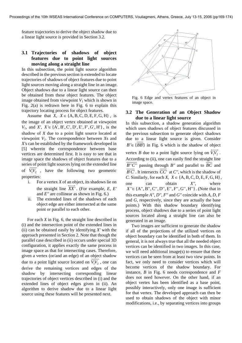
![Shadow maps and projective texturing in X3D · Keywords: X3D graphics, shadows, shadow maps, projective tex-turing 1 Introduction X3D [Web 3D Consortium 2008] is an open standard](https://img.pdfslide.us/doc/110x75/5f3a1fd44777be24b55c0df7/shadow-maps-and-projective-texturing-in-x3d-keywords-x3d-graphics-shadows-shadow.jpg)