Embed Size (px)
Citation preview

SGIRP: A Secure and Greedy
Intersection-Based Routing Protocol
for VANET using Guarding Nodes
Sourav Kumar Bhoi
(Roll. 211CS2275)
Department of Computer Science and Engineering
National Institute of Technology Rourkela
Rourkela – 769 008, India

SGIRP: A Secure and Greedy
Intersection-Based Routing Protocol
for VANET using Guarding Nodes
Dissertation submitted in
May 2013
to the department of
Computer Science and Engineering
of
National Institute of Technology Rourkela
in partial fulfillment of the requirements
for the degree of
Master of Technology
by
Sourav Kumar Bhoi
(Roll. 211CS2275)
under the supervision of
Prof. Pabitra Mohan Khilar
Department of Computer Science and Engineering
National Institute of Technology Rourkela
Rourkela – 769 008, India

Computer Science and EngineeringNational Institute of Technology RourkelaRourkela-769 008, India. www.nitrkl.ac.in
May 22, 2013
Certificate
This is to certify that the work in the thesis entitled SGIRP: A Secure and Greedy
Intersection-Based Routing Protocol for VANET using Guarding Nodes by Sourav
Kumar Bhoi, bearing roll number 211CS2275, is a record of an original research
work carried out by him under my supervision and guidance in partial fulfillment of
the requirements for the award of the degree of Master of Technology in Computer
Science and Engineering Department with specialisation in Information Security.
Neither this thesis nor any part of it has been submitted for any degree or academic
award elsewhere.
Prof. Pabitra Mohan Khilar

AcknowledgmentFirst of all, I would like to express my deep sense of respect and gratitude towards
my supervisor Prof. Pabitra Mohan Khilar, who has been the guiding force behind
this work. I want to thank him for introducing me to the field of Vehicular Ad Hoc
Network and giving me the opportunity to work under him. His undivided faith in
this topic and ability to bring out the best of analytical and practical skills in people
has been invaluable in tough periods. Without his invaluable advice and assistance
it would not have been possible for me to complete this thesis. I am greatly indebted
to him for his constant encouragement and invaluable advice in every aspect of my
academic life. I consider it my good fortune to have got an opportunity to work
with such a wonderful person.
I thank our H.O.D. Prof. Ashok Kumar Turuk and Prof. Bansidhar Majhi for
their constant support in my thesis work. They have been great sources of inspiration
to me and I thank them from the bottom of my heart.
I would also like to thank all faculty members, PhD scholars, my seniors and
juniors and all colleagues to provide me their regular suggestions and encouragements
during the whole work.
At last but not the least I am in debt to my family to support me regularly
during my hard times.
I wish to thank all faculty members and secretarial staff of the CSE Department
for their sympathetic cooperation.
Sourav Kumar Bhoi
Abstract
Vehicular Ad Hoc Network (VANET) is an advance wireless technology in the field
of wireless communication to provide better Intelligent Transportation Services
(ITS). It is an emerging area of research in the field of vehicular technology for
its high mobility and high link disruption. VANET provides better road services
to the end users by providing safety to the passengers and drivers. Multimedia
sharing, e-shopping, safety systems, etc. are some of ITS services provided by
VANET. VANETs are strongly affected by link disruption problem for their high
mobility and randomness. Security is also a main issue in VANET nowadays, which
degrades the network performance. In this thesis, we present a Secure and Greedy
Intersection-Based Routing Protocol (SGIRP) to transmit the data securely from
source (S) to the destination (D) in a shortest path. For this, we have set Guarding
Nodes (GNs) at every intersection to relay the packet from one intersection to
other in a secure manner. GN helps in calculating the updated shortest paths to D,
protects the network from malicious attacks by using authentication scheme and
also recovers the network from Communication Voids (CV). GN plays an important
role in transmitting the data from S to D in a fast and secure way. At last, we
evaluate our proposed SGIRP protocol by deriving and proving the lemmas related
to the protocol. It is also proved that SGIRP protocol shows better performance
than Gytar protocol in terms of shorter time delay (T).

Contents
Certificate ii
Acknowledgement iii
Abstract iv
List of Figures vii
List of Tables viii
1 Introduction 1
1.1 Introduction . . . . . . . . . . . . . . . . . . . . . . . . . . . . . . . . 1
1.2 Intelligent Transportation System . . . . . . . . . . . . . . . . . . . . 4
1.3 VANET Standards . . . . . . . . . . . . . . . . . . . . . . . . . . . . 4
1.4 Routing . . . . . . . . . . . . . . . . . . . . . . . . . . . . . . . . . . 5
1.4.1 Topology Based Routing . . . . . . . . . . . . . . . . . . . . 6
1.4.2 Position/Geographic Based Routing . . . . . . . . . . . . . . . 6
1.4.3 Cluster Based Routing . . . . . . . . . . . . . . . . . . . . . . 7
1.4.4 Geo Cast Based Routing . . . . . . . . . . . . . . . . . . . . . 7
1.4.5 Broadcast Based Routing . . . . . . . . . . . . . . . . . . . . 8
1.5 VANET Security . . . . . . . . . . . . . . . . . . . . . . . . . . . . . 8
1.5.1 Threats to Security Goals . . . . . . . . . . . . . . . . . . . . 8
1.5.2 Secure Routing Protocols in VANET . . . . . . . . . . . . . . 10
1.6 VANET Projects . . . . . . . . . . . . . . . . . . . . . . . . . . . . . 11
1.6.1 VANET Projects in Europe . . . . . . . . . . . . . . . . . . . 11
1.6.2 VANET Projects in USA . . . . . . . . . . . . . . . . . . . . . 13
1.6.3 VANET Projects in Japan . . . . . . . . . . . . . . . . . . . . 13
v

1.7 VANET Simulations . . . . . . . . . . . . . . . . . . . . . . . . . . . 14
1.7.1 VANET Simulators . . . . . . . . . . . . . . . . . . . . . . . . 16
1.8 VANET Applications . . . . . . . . . . . . . . . . . . . . . . . . . . . 19
1.8.1 P2P Applications . . . . . . . . . . . . . . . . . . . . . . . . . 20
1.8.2 Advanced Applications . . . . . . . . . . . . . . . . . . . . . . 21
1.9 Motivation . . . . . . . . . . . . . . . . . . . . . . . . . . . . . . . . . 22
1.10 Objective of Research . . . . . . . . . . . . . . . . . . . . . . . . . . . 23
1.11 Organization of the Thesis . . . . . . . . . . . . . . . . . . . . . . . . 23
1.12 Summary . . . . . . . . . . . . . . . . . . . . . . . . . . . . . . . . . 24
2 Literature Review 25
2.1 Introduction . . . . . . . . . . . . . . . . . . . . . . . . . . . . . . . . 25
2.2 Position Based Routing Protocols . . . . . . . . . . . . . . . . . . . . 25
2.3 Summary . . . . . . . . . . . . . . . . . . . . . . . . . . . . . . . . . 27
3 SGIRP Routing Protocol 28
3.1 Introduction . . . . . . . . . . . . . . . . . . . . . . . . . . . . . . . . 28
3.2 Proposed SGIRP Routing Protocol . . . . . . . . . . . . . . . . . . . 30
3.2.1 Assumptions . . . . . . . . . . . . . . . . . . . . . . . . . . . . 31
3.2.2 Network Model . . . . . . . . . . . . . . . . . . . . . . . . . . 31
3.2.3 Phases of SGIRP Routing Protocol . . . . . . . . . . . . . . . 36
3.3 Summary . . . . . . . . . . . . . . . . . . . . . . . . . . . . . . . . . 44
4 Evaluation of SGIRP Routing Protocol 45
4.1 Introduction . . . . . . . . . . . . . . . . . . . . . . . . . . . . . . . . 45
4.2 Analysis of SGIRP Protocol . . . . . . . . . . . . . . . . . . . . . . . 45
4.3 Summary . . . . . . . . . . . . . . . . . . . . . . . . . . . . . . . . . 58
5 Conclusion 59
5.1 Conclusion . . . . . . . . . . . . . . . . . . . . . . . . . . . . . . . . . 59
5.2 Scope for Further Research . . . . . . . . . . . . . . . . . . . . . . . . 60
Bibliography 61
Dissemination 64
vi
List of Figures
1.1 VANET Architecture. . . . . . . . . . . . . . . . . . . . . . . . . . . . 3
1.2 WAVE, IEEE 802.11p, IEEE 1609 and OSI model [3]. . . . . . . . . . 5
1.3 Projects in USA, European Union and Japan. . . . . . . . . . . . . . 14
1.4 Generation of the realistic mobility model [4]. . . . . . . . . . . . . . 15
1.5 Emerging Applications of VANET. . . . . . . . . . . . . . . . . . . . 21
3.1 Map from OpenStreetMap . . . . . . . . . . . . . . . . . . . . . . . . 32
3.2 (a) Structured city model and (b) Random city model . . . . . . . . . 32
3.3 City model with two intersections and a CV region with area w*x . . 35
3.4 GN registers V by providing KN | in . . . . . . . . . . . . . . . . . . 38
3.5 GN authenticates V . . . . . . . . . . . . . . . . . . . . . . . . . . . . 39
3.6 MFR and B-MFR Protocol used dynamically . . . . . . . . . . . . . 41
3.7 VF Selection by GN . . . . . . . . . . . . . . . . . . . . . . . . . . . . 43
4.1 MFR and B-MFR is used dynamically . . . . . . . . . . . . . . . . . 49
4.2 PL for Gytar and SGIRP . . . . . . . . . . . . . . . . . . . . . . . . . 52
4.3 Single Lane with CV . . . . . . . . . . . . . . . . . . . . . . . . . . . 56
4.4 Multi-Lane with CV . . . . . . . . . . . . . . . . . . . . . . . . . . . 56
vii
List of Tables
3.1 Information at GN . . . . . . . . . . . . . . . . . . . . . . . . . . . . 33
3.3 CV Information at GN . . . . . . . . . . . . . . . . . . . . . . . . . . 34
3.5 D’s Location . . . . . . . . . . . . . . . . . . . . . . . . . . . . . . . . 34
4.1 Notations and Definitions . . . . . . . . . . . . . . . . . . . . . . . . 46
viii

Chapter 1
Introduction
1.1 Introduction
Vehicular Communication is defined as the communication between the vehicles [1].
The main objective of deploying VANET is to reduce the level of accidents. It
has a great impact on passenger’s safety and for the drivers to drive smoothly in
the urban area. As vehicles population increasing day by day the rate of accidents
also increases, so it is necessary for the vehicles to communicate. For example,
suppose a vehicle ’A’ is moving in front of vehicle ’B’ and suddenly ’A’ encounters
with an accident by thunderstorm and it applies brake, it doesn’t want ’B’ should
face the problem, then automatically the brake sensors and rain sensors of ’A’ get
activated and passes the signal to the main unit and then it broadcasts a message
(Alert Message) to other vehicles. After getting the alert message, ’B’ slows down
and further move. By this example, we simply know the use of inter-vehicular
communication and why it is needed.
According to World Health Organization (WHO) the Road-Traffic Injuries
statistics of all countries shows that after 2000 the road accident is a major cause of
death . So, there must be a better traffic system to solve this problem. VANET is
such an advance network which mainly provides Intelligent Transportation System
1
Chapter 1 Introduction
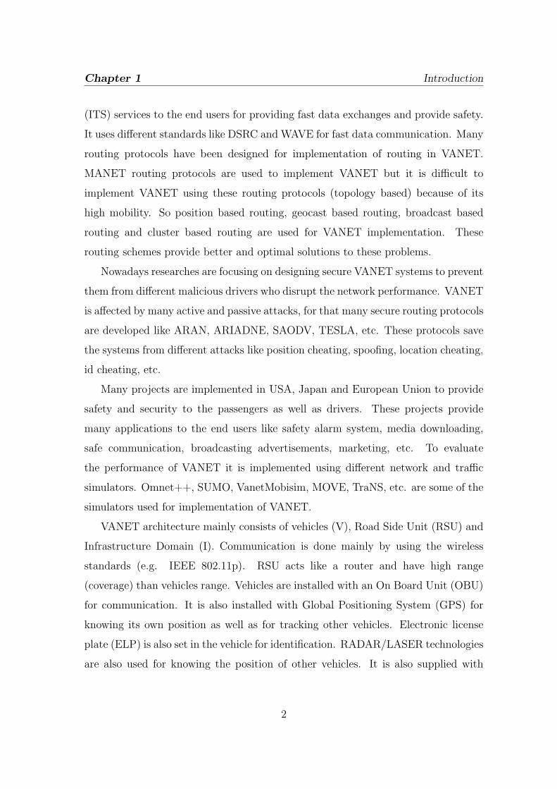
(ITS) services to the end users for providing fast data exchanges and provide safety.
It uses different standards like DSRC and WAVE for fast data communication. Many
routing protocols have been designed for implementation of routing in VANET.
MANET routing protocols are used to implement VANET but it is difficult to
implement VANET using these routing protocols (topology based) because of its
high mobility. So position based routing, geocast based routing, broadcast based
routing and cluster based routing are used for VANET implementation. These
routing schemes provide better and optimal solutions to these problems.
Nowadays researches are focusing on designing secure VANET systems to prevent
them from different malicious drivers who disrupt the network performance. VANET
is affected by many active and passive attacks, for that many secure routing protocols
are developed like ARAN, ARIADNE, SAODV, TESLA, etc. These protocols save
the systems from different attacks like position cheating, spoofing, location cheating,
id cheating, etc.
Many projects are implemented in USA, Japan and European Union to provide
safety and security to the passengers as well as drivers. These projects provide
many applications to the end users like safety alarm system, media downloading,
safe communication, broadcasting advertisements, marketing, etc. To evaluate
the performance of VANET it is implemented using different network and traffic
simulators. Omnet++, SUMO, VanetMobisim, MOVE, TraNS, etc. are some of the
simulators used for implementation of VANET.
VANET architecture mainly consists of vehicles (V), Road Side Unit (RSU) and
Infrastructure Domain (I). Communication is done mainly by using the wireless
standards (e.g. IEEE 802.11p). RSU acts like a router and have high range
(coverage) than vehicles range. Vehicles are installed with an On Board Unit (OBU)
for communication. It is also installed with Global Positioning System (GPS) for
knowing its own position as well as for tracking other vehicles. Electronic license
plate (ELP) is also set in the vehicle for identification. RADAR/LASER technologies
are also used for knowing the position of other vehicles. It is also supplied with
2

Chapter 1 Introduction
high battery power. A Certification Authority (CA) exists in the architecture for
providing services (e.g. security and TCP/IP) and applications. Fig. 1.1 shows the
architecture of VANET.
Figure 1.1: VANET Architecture.
Recently many developments and researches have been made under VANET.
People are working on the issues like routing, broadcasting, security and traffic
management.
The organization of the chapter is desribed as follows: section 1.2 presents about
the ITS services. Section 1.3 describes about the VANET standards. Section 1.4
describes about the routing protocols. Section 1.5 describes about the threats and
VANET security. Section 1.6 describes about the current projects implemented in
USA, Japan and Europe. Section 1.7 presents about the simulation, where many
simulators are described related to VANET simulation. Section 1.8 describes about
the current applications provided by VANET systems. In section 1.9 and 1.10, we
present our motivation and objective of research respectively. In section 1.11, we
present the organization of the thesis. Section 1.12 presents the summary of the
chapter.
3

Chapter 1 Introduction
1.2 Intelligent Transportation System
Intelligent Transportation System means the vehicle itself acts as a sender, receiver
and router for broadcasting information. As discussed earlier, the VANET consists
of RSUs and the vehicles are installed with OBU, GPS, ELP, etc. ITS provides two
types of communication in VANET: first is Vehicle to Vehicle (V2V) and second is
Vehicle to Infrastructure/Infrastructure to Vehicle (V2I/I2V). Fig. 1.1 shows V2V
communication and V2I/I2V communication.V2V communication uses multi-hop
communication (multicasting/broadcasting) for transmission of data. Inter-vehicle
communication consists of two types of communication: first is nave broadcasting
which produces beacons at regular interval. The main demerit of using nave
broadcasting is collision of messages due to much more generation of messages.
Second is Intelligent Broadcasting which generates messages on demand. The
collision reduces in this method of data transmission. V2I communication uses
single hop communication (RSU broadcasts message to the vehicles in range). It
has a high bandwidth link between the vehicles and RSUs. RSUs determine the
vehicle speed and if the vehicle speed is more than the limit than RSU broadcasts a
message in the form of visual warning or alarm.
1.3 VANET Standards
DSRC is a standard developed by United States [3]. It is a short to medium
range communication service used for both V2V and V2I communication. US
Federal Communication Commission (FCC) sets 75 MHz of spectrum at 5.9 MHz
for DSRC. DSRC spectrum has 7 channels [3]. Each channel is 100 MHz wide. In
2003, American Society for Testing and Materials (ASTM) sets ASTM-DSRC which
was totally based on 802.11 MAC layer and IEEE 802.11a physical layer [3]. The
main problem with IEEE 802.11a with Data Rate of 54 Mbps is it suffers from
multiple overheads. Vehicular scenarios demands high speed data transfer and fast
communication because of its high topological change and high mobility. For this
4

Chapter 1 Introduction
the DSRC is renamed to IEEE 802.11p Wireless Access in vehicular Environments
(WAVE) by the ASTM 2313 working group. This works on MAC layer and physical
layers. WAVE consists of Road Side Unit (RSU) and On-Board Unit (OBU). WAVE
uses OFDM technique to split the signals. Fig. 1.2 shows the WAVE, IEEE 802.11p,
IEEE 1609 and OSI model.
Figure 1.2: WAVE, IEEE 802.11p, IEEE 1609 and OSI model [3].
1.4 Routing
Routing is a vast concept used in MANET and VANET environment. Many
routing protocols have been designed for communication between the nodes in
an ad hoc environment. In VANET, routing is a difficult task to achieve
because of its high mobility. The main issues in VANET which requires routing
are network management, traffic management, broadcasting, mobility, topological
change, Quality of Service (QoS), fast data transfer, etc. These are the challenging
elements which require efficient routing techniques. Routing protocols are divided
into Topology Based, Position Based, Cluster Based, Geo Cast Based and Broadcast
Based. In this section, we survey briefly on different routing protocols used in
VANET implementations.
5
Chapter 1 Introduction
1.4.1 Topology Based Routing
Topology based routing protocol is divided into proactive and reactive routing
protocols [6]. In proactive routing protocols, no route discovery takes place as
the routes are predefined. Maintenance of unused routes leads to high network
load. DSDV: Destination-Sequenced Distance-Vector Routing, OLSR: Optimized
Link State Routing Protocol, FSR: Fisheye state routing, CGSR: ClusterHead
Gateway Switch Routing, WRP: The Wireless Routing Protocol, TBRPF: Topology
Dissemination Based on Reverse-Path Forwarding, etc. are some of the proactive
routing protocols.
In reactive routing protocols, the route discovery takes place on demand. So,
the network load reduces as only the route currently in use is maintained. DSR:
Dynamic Source Routing, AODV: Ad Hoc on Demand Distance Vector, TORA:
Temporally Ordered Routing Algorithm, JARR: Junction-based Adaptive Reactive
Routing, PGB: Preferred Group Broadcasting, etc. are some of the reactive routing
protocols.
Hybrid routing protocols discovers the routes between the zones to reduce
network load. Proactive protocols are used in intra-zone routing and reactive
protocols are used in inter-zone routing. ZRP: Zone routing protocol, HARP: Hybrid
Ad Hoc Routing Protocol, etc. are some of the zone routing protocols.
1.4.2 Position/Geographic Based Routing
Position based routing uses geographic location information for the selection of next
hop to forward the message. It uses beaconing to broadcasts the messages [6]. GPSR:
Greedy Perimeter Stateless Routing, DREAM: Distance Routing Effect Algorithm
for Mobility, CAR: Connectivity Aware Routing Protocols, GSR: Geographic
Source Routing, A-STAR: Anchor-Based Street and Traffic Aware, PRB-DV:
Position-Based Routing with Distance Vector Recovery, GRANT: Greedy Routing
with Abstract Neighbor Table, GpsrJ+, STBR: Street Topology Based Routing,
6

Chapter 1 Introduction
GyTAR: Greedy Traffic Aware Routing protocol, LOUVRE: Landmark Overlays for
Urban Vehicular Routing Environments, DIR: Diagonal-Intersection-Based Routing
Protocol, ROMSGP: Receive on Most Stable Group-Path, AMAR: Adaptive
movement aware routing protocol, EBGR: Edge node based greedy routing
protocol, B-MFR: Border-node based most forward within radius routing protocol,
ARBR: The Associativity-Based Routing, MORA: Movement-Based Routing,
VGPR: Vertex-Based predictive Greedy Routing, MIBR: Mobile Infrastructure
Based VANET Routing, DTSG: Dynamic Time-Stable Geocast Routing, TO-GO:
Topology-assist Geo-Opportunistic Routing, CBF: Contention-Based Forwarding,
VADD: Vehicle-Assisted Data Delivery, GeOpps: Geographical Opportunistic
Routing, GeoDTN+Nav, etc. are some of the position based routing protocols.
1.4.3 Cluster Based Routing
In cluster based routing, a group of nodes are identified as a cluster and
in each cluster a cluster head exists which sends the message [6]. CBR:
Cluster Based Routing, CBLR: Cluster Based Location Routing, CBDRP:
Cluster-Based Directional Routing Protocol, TIBCRPH: Traffic Infrastructure
Based Cluster Routing Protocol with Handoff, LORA-CBF: Location Routing
Algorithm with Cluster-Based Flooding, COIN: Clustering for Open IVC Network,
HCB: Hierarchical Cluster Based Routing, etc. are some of the cluster based routing
protocols.
1.4.4 Geo Cast Based Routing
In this routing, message is delivered to a region by multicasting [6]. IVG:
Inter-Vehicle Geo Cast, DG-CASTOR: Direction-based Geo Cast Routing Protocol
for query dissemination in VANET, DRG: Distributed Robust Geo Cast, ROVER:
Robust Vehicular Routing, DTSG: Dynamic Time-Stable Geo Cast Routing, etc.
are some of the Geo Cast routing protocols.
7

Chapter 1 Introduction
1.4.5 Broadcast Based Routing
This is a frequent routing technique in which messages are broadcasted and shared
among the vehicles and between vehicle and infrastructure. BROADCOMM, UMB:
Urban Multi-hop Broadcast Protocol, V-TRADE: Vector Based Tracing Detection,
DV-CAST: Distributed vehicular broadcast protocol, EAEP: Edge-aware epidemic
protocol, SRB: Secure Ring Broadcasting, PBSB: Parameterless Broadcasting in
Static to Highly Mobile Wireless Ad Hoc Network, etc. are some of the broadcast
based routing protocols [6].
1.5 VANET Security
Security in VANET is a challenging problem for the researchers in the era of cyber
threats [3]. The message passes from one vehicle to other vehicle may be trapped
or hacked by an intruder or imposter who creates vulnerability in the systems
performance. In VANET, many types of attacks occurs to the system like Position
Cheating GPS Information Hacking, ID Cheating, Message Modification, Spoofing,
etc. Malicious drivers can create problems in the traffic which leads to accident
and traffic jam. So, the vehicles should use security mechanisms to resist these
threats. In this section, we present the threats to the VANET system and the
security mechanisms to check the attacks.
1.5.1 Threats to Security Goals
There are three types of security goals: first is Confidentiality, second is Integrity
and third is Availability. But these goals are strongly affected by the malicious
drivers. Confidentiality is affected by:
� Snooping: Accessing of unauthorized information.
� Traffic Analysis: Analyzing the traffic (collection of information/transactions).
8

Chapter 1 Introduction
Integrity is affected by:
� Data Modification: means intercepting and modifying the data.
� Replay Attack means saving a copy of the data and later use it for replaying.
� Masquerading: means impersonating some other vehicle by providing fake ID
and advertises as a legal node.
� Repudiation: Denial of message sending.
� Global Positioning System Attack: means providing fake and false position
information by intercepting the message.
� Sybil Attack: means generating identities and cheating with fake identities.
� Message Tempering: means modification of messages.
� Position Cheating/Faking: means providing fake information about positions.
� Tunneling: creates a tunnel and injection of fake data.
� Message Alteration: means physical damage of inter-vehicular communication.
Availability is affected by:
� Black Hole Attack: means dropping of packets which creates disruption in the
network.
� Denial of Service: means sending bogus requests by which the vehicles are
overloaded and crashed.
� Spamming: increases the latency in the system.
9

Chapter 1 Introduction
1.5.2 Secure Routing Protocols in VANET
Many secure routing protocols have been designed and implemented in the real
life scenario which uses the concepts of Authentication, Digital Signature, Public
Key Infrastructure (PKI), etc. to secure the system from different active and
passive attacks. The secure routing protocols are discussed as follows: ARAN
stands for Authenticated Routing for Ad Hoc Networks and it is same as AODV
protocol with authentication schemes at the time of route discovery. ARIADNE is
another protocol which is an extension of DSR with the concepts of symmetric key
cryptography. It uses the TESLA scheme for routing. TESLA is a secure routing
protocol which stands for Timed Efficient Stream-Loss Tolerant authentication.
It uses broadcast authentication scheme by applying a signature in the message.
CONFIDANT protocol stands for Cooperation of Nodes: Fairness in Dynamic Ad
Hoc Networks and it is designed to support DSR. DCMD stands for Detecting and
Correcting Malicious Data. This protocol is used for detection of faulty information
and identification of malicious vehicle or node. SAODV is a secure AODV routing
protocol used for providing authentication, integrity and non-repudiation. It uses
digital signature for authentication and hash chains for hop count information.
SEAD stands for Secure Efficient Ad Hoc Distance Vector Routing. It is used for
removal of faulty routing state information in other nodes. It is based on DSDV
routing protocol and uses hash chains for providing authentication. SLSP stands for
Secure Link State Routing Protocol. It is a proactive routing protocol which protects
the link state information and topology discovery of the network. It is used in Zone
Routing Protocol. SPAAR stands for Secure Position Aided Ad Hoc Routing, which
uses position information for routing. It uses asymmetric cryptography for message
confidentiality and integrity. SLOSR is an improved secure OLSR protocol used
for providing authentication to the packets and prevention to the replay attacks.
It uses HMAC codes and time exchanges schemes in the nodes to protect against
malicious nodes. WATCHDOG-PATHRATER is an improved version of DSR. It
observes and analyzes the reports made by other nodes for detection of an imposter
10

Chapter 1 Introduction
node. Watchdog manages a buffer of transmitted packets and analyzes the node
which forwards the packet. Path Rater describes a metric for estimation of link with
respect to other links reliability. ECDSA stands for Elliptic Curve Digital Signature
Algorithm and it is used mainly for providing robust security and protection against
different attacks.
1.6 VANET Projects
VANET implementation in a real time system is a challenging task. Many such
implementations have been deployed in these last years and implementing such
projects in a real time system requires complete simulation by measuring the
performance of the system. Many new projects have been made by the government
to develop ITS. US, Japan and European nations are using the ITS systems
by implementing VANET in the urban areas. Early developments mainly focus
on the protocol infrastructure (WAVE, IEEE 802.11p and DSRC). But now it
is acquiring the new concepts of messaging system and application architecture.
Many car producing companies like BMW, Audi etc. are using the ITS systems
for passenger safety. VSC (Vehicle Safety Communication) is a project in USA,
C2C-CC (Car-to-Car Communication Consortium) project in European nations and
ASV (Advance Safety Vehicle Program) project and VII (Vehicle Infrastructure and
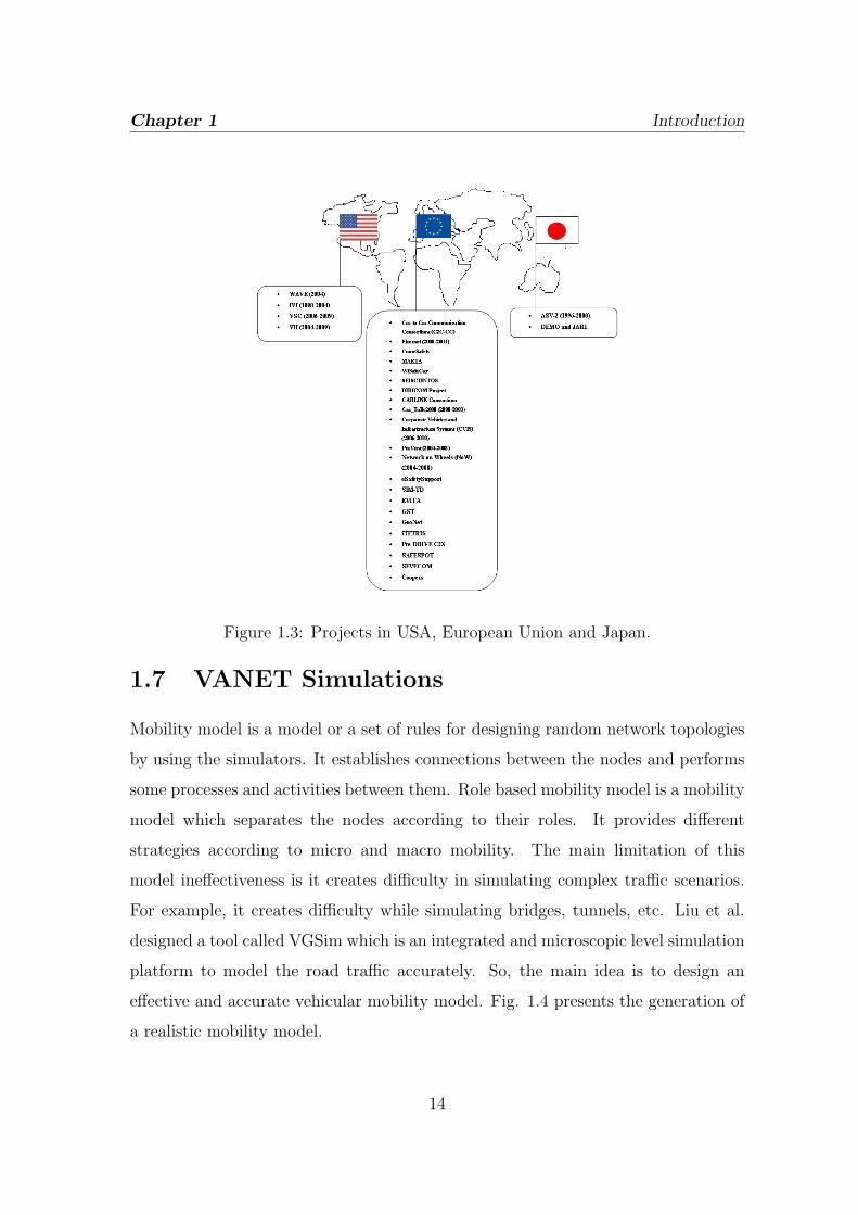
Integration) in Japan are some of the government projects under these schemes. Fig.
1.3 presents the projects in USA, European Union and Japan. Many such VANET
projects have been surveyed and presented as follows:
1.6.1 VANET Projects in Europe
C2C-CC project started in 2001 which uses IEEE 802.11 WLAN in 100 meters.
This project is mainly designed for vehicle to vehicle communication. Fleetnet
(2000-2003) project uses GPS information for V2V and V2I communication. It
is mainly deployed in urban areas and simulated by Fleetnet Demonstrator. NoW
11

Chapter 1 Introduction
(2004-2008) is a project mainly deployed in Germany and it is funded by Dailmer,
BMW, and Volkswagen. This is mainly developed for providing security. It supports
C2C- Communication Consortium in communication. PreVent (2004-2008) project
uses sensors, maps and communication system. Its trial has 23 cars, trucks and
different devices. Its main applications are safety and collision control. CVIS
(2006-2010) is a project mainly developed for providing V2V communication. Its
main applications are traffic control systems and network monitoring. CarTalk
(2000-2003) is a project used for Advance Driver Assistance (ADAS), Advance
Cruise Control and Collision Avoidance Systems. CARLINK project is used
for generating intelligent wireless communication between vehicles. Its main
applications are weather forecasting, city traffic management and information
broadcasting. DIRICOM is a Spanish project financed by Spanish Regional Ministry.
SEISCINTOS is a project which mainly concentrates on providing intelligent
communication in MANET, VANET and WSN. This project mainly aimed to
provide ubiquitous services to the users. WiSafeCar stands for Wireless Traffic
safety network between cars. It is a project mainly designed for traffic management
and road safety. MARTA stands for Mobility and Automation through advanced
Transport Networks. It is a Spanish project for providing safety and efficiency in
ITS. ComeSafety provides safety in V2V and V2I communication by supporting
safety forum. Coopers stands for CO-Operative Systems for Intelligent Road Safety.
This project provides traffic safety between vehicles and infrastructure by designing
telematics applications. eSafetySupport is a project which aims to provide safety
systems and supports European Commissions 2001 goal of reducing road fatalities
by 2010. EVITA stands for E-Safety Vehicle Infrastructure Protected Applications.
It provides secure communication. GST stands for Global System for Telematics.
Its main aim is to deploy telematics services to the end users. GeoNet stands
for Geographic Addressing and Routing for Vehicular Communications. GeoNet
project extends the work of C2C-CC by enhancing its specification and interfacing
with IPv6.iTETRIS stands for An Integrated Wireless and Traffic platform for
12

Chapter 1 Introduction
Real-Time Road Traffic Management Solutions. It works on emissions, travel
time, traffic management etc. Pre-DRIVE C2X project mainly focuses on driver
assistance systems and safety communication. SAFESPOT mainly focuses on
safety communication between the vehicles. SEVECOM stands for Secure Vehicles
COmmunication. It is a European-Union project which provides security to the
system. SIM-TD stands for Safe Intelligent Mobility-Test Area Germany and it
provides communication between V2V and V2I for traffic safety.
1.6.2 VANET Projects in USA
WAVE (2004) stands for Wireless Access in Vehicular Environments. It extends
many projects in USA like IVI, VSC, VII, etc. IVI (1998-2004) stands for Intelligent
Vehicle Initiative which provides road safety.VSC (2006-2009) stands for Vehicular
Safety Communication for providing safety. It works by coordination with Highway
Traffic Safety Administration. VSC-2 includes protocols, messaging, systems and
interface.VII (2004-2009) stands for Vehicle Infrastructure Integration which started
in Detriot. It integrates with Ford, General Motors, BMW, Honda, Toyota,
Volkswagen, Daimler-Chrysler, Nissan for providing better communication.
1.6.3 VANET Projects in Japan
ASV (1996-2000) stands for Advanced Safety Vehicle. It is extended to ASV-3 in
2001 and ASV-4 in 2005 by providing automatic collision avoidance system and
navigation system. It is supported by Honda, Mitsubishi, Suzuki and Toyota.
DEMO started in 2000 for providing cooperative driver support system. It uses
band of 5.8 GHz and CSMA protocols for communication. JARI stands for Japan
Automobile Research Institute which conducts many trials for the projects and it
evaluated the USA projects and European Union Projects. It mainly focuses on
security and safety.
13
Chapter 1 Introduction
Figure 1.3: Projects in USA, European Union and Japan.
1.7 VANET Simulations
Mobility model is a model or a set of rules for designing random network topologies
by using the simulators. It establishes connections between the nodes and performs
some processes and activities between them. Role based mobility model is a mobility
model which separates the nodes according to their roles. It provides different
strategies according to micro and macro mobility. The main limitation of this
model ineffectiveness is it creates difficulty in simulating complex traffic scenarios.
For example, it creates difficulty while simulating bridges, tunnels, etc. Liu et al.
designed a tool called VGSim which is an integrated and microscopic level simulation
platform to model the road traffic accurately. So, the main idea is to design an
effective and accurate vehicular mobility model. Fig. 1.4 presents the generation of
a realistic mobility model.
14

Chapter 1 Introduction
Figure 1.4: Generation of the realistic mobility model [4].
Vehicular Mobility model is mainly divided into two types : first is Microscopic
type which differentiates each vehicle distinctly, means each vehicle has its own
behavior and the second is Macroscopic type which mainly focuses on vehicular
density, streets, lights, buildings, [4] etc. The mobility model can also be described
by Traffic Generator and Motion Generator. Traffic generator generates random
topologies by knowing the positions of the nodes and motion constraints are
generated by the behavior of vehicles, drivers and pedestrians.This shows the method
of generating a realistic mobility model by taking traffic generator and motion
constraints as the main elements. VANET simulation required a complete, accurate
and realistic mobility model which is gained by collecting patterns from mobility
traces. We survey on some models which generates traces which are used by the
mobility model. The models are presented as follows :
Survey models are the models which present the real human behavior and helps
in generating traces which is used in the mobility model [4]. It records the human
behavior, activities, control, tasks, etc. in urban networks .For example, Udel
mobility model is designed for simulation of urban networks. In this model firstly
15

Chapter 1 Introduction
a graph is created and then nodes are placed and the behavior is recorded. Event
driven model is a model to generate traces which is used by the mobility model.
This helps in developing a probabilistic mobility model . WLAN mobility model
is an event driven model. The main disadvantage of this model is it does not
concentrate on node relationship. Many software oriented models have been designed
like VISSIM, CORSIM, TRANSIM, etc. which generates the traces. VanetMobisim
also generates traces of streets, maps roads, etc. The main disadvantage of this
model is it failed to generate realistic details. Synthetic model uses mathematical
formulas and equations to generate the traces. They mainly develop a mathematical
model and compare it with the realistic models. Synthetic model is divided into five
categories:
� Stochastic Model: describes the random motion and behavior.
� Traffic stream: mainly analyzes the mechanical functions.
� Car Following Model: monitors the behavior and tasks of vehicle to vehicle
communication.
� Queue Model: describes the road as a buffer and vehicles as the nodes standing
in a queue.
� Behavioral Model: describes about the activities of the nodes.
1.7.1 VANET Simulators
VANET is implemented using robust and effective simulators. The main element
in VANET simulation is he the generation of a mobility model. The main building
blocks in designing a mobility model are: visualization tool, output, platform and
a class which connects the mobility model and network simulator. In this section
we present the different types of Traffic Simulators, Network Simulators, Isolated
Vehicular Models, Embedded Vehicular Models and Advanced Vehicular mobility
models.
16

Chapter 1 Introduction
Traffic Simulators
Traffic simulators are mainly designed to simulate the urban intersections and
highways [4]. This is an important tool for traffic engineering. For example,
TRANSIM or VISSIM, CORSIM, PARAMICS, CARISMA, SHIFT, etc. are some
of the traffic simulators for simulation of the microscopic and macroscopic levels.
These simulators are validated and used for providing accurate mobility models.
The main disadvantages of traffic simulators are they take more time in planning
and transportation which increases the time complexity. For using these simulators
the end users require a license. Many open source traffic simulators are available
nowadays to handle large traffic like SUMO (Simulation of Urban Mobility). SUMO
generates traces which are used by network simulators. For traffic generation it takes
the route assignments and for motion constraints it contains parsers for TIGER.
MOVE (Mobility Model Generator for Vehicular Networks) tool is used to simplify
the SUMO configuration and adds a GUI environment to it.
Network Simulators
Network simulators play an important role in managing and controlling the network
parts [4]. These are available in the market as commercial as well as open source.
Commercial tools include Opnet and Qualnet with high network protocols and
wireless suite. Omnet++ is a free tool for academic purposes but for commercial
purpose it requires a license. Open source simulators are like ns-2 which is
mostlyused for MANET simulation and Glomosim is a tool same as ns-2 for
simulation of MANET. Swans, GTNets (Georgia Tech Network Simulator), etc.
are some of the network simulators used for MANET simulation.
Isolated Vehicular Model
Isolated vehicular models are the mobility models with lack of interaction with the
network simulators [4]. It is divided into four parts: legacy mobility model, improved
17

Chapter 1 Introduction
motion constraints, improved traffic generator and improved motion constraints and
traffic generator. These are categorized into four types of models:
1. Legacy Mobility Model:
Many legacy mobility models have been designed like Random Waypoint
model, gauss-Markov model, Reference Point Group model, Random Walk
model, Node Following model [4]. All models generate linear speed movement.
These models are mainly meant for MANET study. For VANET, Freeway
model and Manhattan model are designed.
2. Improved Motion Constraints:
After legacy models BonnMotion tool is designed to implement random
mobility model like ManHanttan. Obstacle Mobility model is also designed
which use Voronoi tessellations and random corners. Voronoi model is also
designed for the generation of smoother roads.
3. Improved Traffic Generator:
These are the extended versions of improved motion constraints models.
GEMM tool and CanuMobisim tool generates a realistic mobility model.
GEMM has the concept of human mobility dynamics (AP: Attraction points).
CanuMobisim implements the car mobility model (CFM) and traffic stream
model.
4. Improved Motion Constraints and Traffic Generator:
This creates interaction between the traffic generator and motion constraints.
STRAW (Street Random Waypoint) tool is the tool which contains these two
modules. Motion constraints module is obtained by using the TIGER database
which contains the urban topologies and the other traffic generator module
implement the human patterns. It mainly based on SWANS platform. After
this SSM/TSM (Stop Sign Model/Traffic Sign Model) and GMSF (Generic
Mobility Simulation Framework) are developed. Then VanetMobisim is
18

Chapter 1 Introduction
designed to achieve more realism. Udel Model is then developed to implement
more complex urban networks.
Embedded Models
Embedded models mainly signify the union of mobility and networking modules [4].
Groovenet/Groovesim is the first tool to provide embedded vehicular mobility model.
Groovesim is the model and Groovenet is the project for modeling. City Model tool
is designed for embedding, implementing and testing routing protocols. Then Bononi
et al. designed MoVes which provides driving patterns and a better mobility model.
Gorgorin et al. also found a simulator embedded with mobility and networking
capabilities. Vyyuru et al. also designed a tool called Automesh which consists of a
radio propagation block, network simulator and driving simulator. Then NCTUns is
developed for providing better mobility and networking capabilities. It can simulate
802.11a, 802.11b, 802.11p MAC.
Advance Mobility Models
These models provide a better networking features and motion features. It is also
divided into open source and commercial based models. Open source models are
like TraNS tool with SUMO and ns-2. One project named VGrid is also launched
for the study on traffic accidents after using the alert messages. Then MobiReal is
developed which is mainly based on GTNets. These are also called as Federated
Mobility Models.
1.8 VANET Applications
At last, we survey on the emerging applications of VANET technology. As we
know, V2V and V2I communication provides high mobile applications by which the
producers (car manufacturers) as well as consumers (End users) gains better facilities
and services. VANET provides application like e-Safety, traffic management,
19

Chapter 1 Introduction
driver comfort support, maintenance, media services, gaming, e-Shopping, crime
investigation, defense, etc. It also provides local services in restaurants, theaters
etc. by using a grid network. VANET uses P2P (Peer-to-Peer) applications for
providing services to the customers. P2P applications are divided into four categories
for handling the data.
1.8.1 P2P Applications
Vehicular Sensor Applications uses sensors for monitoring and sharing the data.
Vehicles use GPS, video cameras, detectors, sensors, RADAR, LASER, vibration,
etc. to sense the data. MobEyes is a middleware which provides urban monitoring
and services. Cartel, Pothol Patrol (P2), Zebranet, SWIM, Metrosense, DFT-MSN
(Delay/Fault-Tolerant Mobile Sensor Network), CENS, Irisnet, and Sense Web,
Urbanet, etc. are some of the data monitoring projects which sense the data
and share the information. Data is downloaded from AP (Access Points) and it
is communicated between the APs and vehicles or vehicles to vehicle. SPAWN ,
CarTorrent, CodeTorrent and MOVi (Mobile Opportunistic Video-on-Demand) are
some of the protocols for data distribution. Advertisements are mainly done by the
business companies to spread the message in the form of audio, video and images.
The main applications include car parking information and location awareness
information. Producer and Consumer Application includes V3 (Vehicle-to-Vehicle
live Video) streaming. Tavarau is a communication system used for video streaming
by using 3G services. Fleanet is a market place which creates a virtual environment
of market. By this one can easily find the routes and the product in the market and
streets. Roadspeak is an architecture designed for the drivers to chat smoothly and
exchanges. It is a main application for safety.
20

Chapter 1 Introduction
1.8.2 Advanced Applications
Nowadays many new VANET applications are developing which provides safety,
security and establishes strong relations between producer and consumer.
Applications in VANET are mainly categorized into four parts: e-Safety, Traffic
Management, Enhanced Driving Support and Maintenance. Figure 1.5 shows the
advanced vanet applications.
Figure 1.5: Emerging Applications of VANET.
1. e-Safety Applications:
Traffic Signal Warning System, Stop Sign Warning System, Left Turn
Assistant, Emergency Vehicle Approaching Warning System, Intersection
Collision Warning system, Pedestrian Crossing Information System,
Emergency Vehicle Signal Preemption, Vehicle Safety Inspection System,
Electronic License Plate, Electronic Driver License Plate, Stolen Vehicle
Tracking, Crime Investigation, Breakdown warning system, Pre-crash Sensing
system, Curve Speed warning System, Accident warning system, Speed
Breaker Warning , Rail Collision Warning, Work Zone Warning, etc.
2. Traffic Management Applications:
Area Access Control, Crash Data Collection, Weather Data Collection,
Intelligent Traffic Flow Control, Cooperative Planning, Adaptive Cruise
Control, Traffic Management, etc.
3. Maintenance Applications:
21

Chapter 1 Introduction
Software Updating, Wireless Diagnosis, Safety Recall Notice, Hardware,
Maintenance, Repair Notification, etc.
4. Enhanced Driver Support Applications:
Internet Service Provision, Fuel Information. Media services, Region
of Interest Notification, GPS Information, Location Awareness, Parking
Spot Information, Route Information Downloading, Map Updating and
Downloading, etc.
1.9 Motivation
The main research areas in VANET are routing, broadcasting, traffic control,
congestion control, security, etc. Researchers are also working on domains
like architecture designing, protocol designing, effective hardware and software
generation, etc. The main problem with VANET is its high mobility which leads to
link failure and generation of sparse regions which we call as Communication Voids
(CV). Routing in VANET is a critical problem to solve. To transmit the data from S
to D is a difficult task to implement in such a random environment. So there should
be an optimal solution to this problem. Security is also a major issue in the routing
protocols and there should be a security module to check the malicious attacks from
the malicious drivers.
Many routing protocols have been designed so far to implement MANET and
it is also implemented in VANET. Topology based routing protocols are used to
implement VANET but it undergoes several problems like frequent topology change
and link disruption. The best method for routing in VANET is done by the
implementation of location service protocol. By this protocol, a vehicle knows the
approximate position of D and this type of routing is known as Position-Based
routing. Position-Based routing techniques are highly used in VANET environments
because there is no maintenance of routes, network overhead, etc. GPSR, GPCR,
A-STAR, Gytar, etc. are some of the position based routing protocols to provide
22

Chapter 1 Introduction
better ITS services.
1.10 Objective of Research
The main objectives we find from the motivation to work in VANET are discussed
as follows:
� Routing Problem: To select such a path to send the data which has a low cost
and which takes less end-to-end delay.
� Security Problem: To design such a robust authentication scheme by which
vehicle in the network can be recognized as a genuine node or malicious node.
� Communication Void Problem: As mobilty of the vehicles is more, connection
losts between the vehicles and communication voids are generated in the areas
by which vehicles are unable to communicate. So there should be a recovery
strategy to check sparse region problem.
1.11 Organization of the Thesis
The rest of the thesis is organized as follows:
1. Chapter 1: In this chapter we have discussed about the introduction to
VANET, motivation and objective of our research.
2. Chapter 2: In this chapter we present the literature review where we have
described some existing works on routing.
3. Chapter 3: In this chapter we present our proposed SGIRP routing protocol.
4. Chapter 4: In this chapter we evaluate our protocol by deriving and proving
the lemmas related to the protocol.
5. Chapter 5: At last we concluded in this chapter.
23

Chapter 1 Introduction
1.12 Summary
In this chapter, we mainly discusses about the main research areas in VANET,
its development and status. We have also described about the security, projects,
simulations and the current applications in VANET.
24

Chapter 2
Literature Review
2.1 Introduction
Designing of advance routing technique is a great challenge in computer networking
[2, 6, 7, 8]. Getting an optimal routing solution is a hard task and to implement
it in a real life situation is a vast problem. In the case of VANET it is difficult to
implement a routing protocol because of its high mobility and randomness. The
nodes are so mobile that it leads to link disruption and link failure which hindered
the data communication.
The organization of the chapter is presented as follows: section 2.2 presents the
position based routing protocols used in the implementation of VANET. Section 2.3
presents the summary of the chapter.
2.2 Position Based Routing Protocols
Many routing protocols have been designed so far to implement MANET and it
is also implemented in VANET [1]. Topology based routing protocols are used
to implement VANET but it undergoes several problems like frequent topology
change and link disruption. The best method for routing in VANET is done by
the implementation of location service protocol. By this protocol, a vehicle knows
25

Chapter 2 Literature Review
the approximate position of D and this type of routing is known as Position-Based
routing [7, 8]. Position-Based routing techniques are highly used in VANET
environments because there is no maintenance of routes, network overhead, etc.
GPSR [16], GPCR [13], A-STAR [14], Gytar [15], etc. are some of the position
based routing protocols to provide better ITS services.
Karp et al. [16] proposed a protocol GPSR which stands for Greedy Perimeter
Stateless routing and it is a well known position based routing protocol in which two
strategies are used to send the data from S to D. In the first strategy, vehicle V1
sends the data to vehicle V2 which is nearer to D, but if vehicle V1 itself nearer to
D than other vehicles, it uses the recovery strategy by switching to perimeter mode.
Lochert et al. [13] proposed a protocol known as GPCR in which the forwarding
node is selected to be the junction node and the recovery strategy for GPCR is same
as GPSR.
Liu et al. [14] designed a protocol known as A-STAR which mainly focuses on
the connectivity of routes and the main goal is to send the packets successfully to
the D.
Jerbi et al. [15] proposed Gytar protocol which is a greedy and intersection
based routing protocol which sends the data by selecting the junctions. To choose the
junction, vehicle calculates the score of each neighboring junctions by considering the
density and curvemetric distance [15]. To recover from the local optimum problem,
it uses the carry and forward mechanism. This technique might increase the delay.
These are some of the routing protocols which work well in the city environment.
The main challenges behind such routing protocols are high mobility and security.
Due to high probability link failure occurs and the recovery strategies discussed
above work well to this situation. But at some time, the recovery strategies may fail
due to huge sparse regions in the network. So, if a past knowledge (K) about the
CV region is known then there is a less chance of encountering a sparse region in
the path. SGIRP protocol uses this recovery technique to avoid CV regions in the
path. Security is also a major issue in the routing protocols and there should be a
26

Chapter 2 Literature Review
security module to check the malicious attacks form the malicious drivers. SGIRP
routing protocol provides a robust security module to check vehicles authentication
and protect vehicles from attacks. SGIRP also solves the shortest path problem
by using Dijkstra algorithm. The SGIRP protocol is totally described in the next
chapter.
2.3 Summary
In this chapter, we have discussed briefly about the position based routing protocols,
to implement VANETrouting in the city scenario. We have discussed about the well
known GPSR, Gytar, A-Star and GPCR routing protocol and in chapter 3 we have
discussed about our SGIRP protocol and in chapter 4 we have compared our SGIRP
protocol with Gytar protocol in terms of shorter time delay (T).
27

Chapter 3
SGIRP Routing Protocol
3.1 Introduction
In the current era of research VANET is the most advance system which
revolutionizes the world of wireless technology [3, 5]. VANET provides safe
and secure communication between the vehicles by implementing robust designs,
architectures, protocols, hardware and software. Many car producing companies
like BMW, Daimler, Ford, etc. are implementing VANET technology to provide
safety and security to the end users. Many VANET projects are implemented
in many parts of the world like USA, European Union and Japan [3]. In USA,
many projects are implemented like WAVE, VII, VSC, IVI, etc. Europe is a region
where VANET projects are deployed widely like C2C-CC, Comesafety, MARTA,
Wisafecare, DIRICOM, CARLINK, PreVent, CarTalk2000, EVITA, eSafetySupport,
SAFESPOT, etc. Japan has also projects like ASV-2, DEMO, JARI, etc. These
projects mainly provides ITS services to the end users (drivers and passengers) like
use of safety systems, media sharing, e-shopping, security, etc [20].
Nowadays the main research areas in VANET are routing, broadcasting, traffic
control, congestion control, security, etc. Researchers are also working on domains
like architecture designing, protocol designing, effective hardware and software
28

Chapter 3 SGIRP Routing Protocol
generation, etc. The main problem with VANET is its high mobility which leads
to link failure and generation of sparse regions which we call as Communication
Voids (CV). Routing in VANET is a critical problem to solve. To transmit the
data from S to D is a difficult task to implement in such a random environment.
So there should be an optimal solution to this problem. The city area mainly
consists of intersections which connects the roads. Roads consist of vehicles which
can communicate with other vehicles by using IEEE wireless standards. VANET uses
many types of standards like WAVE and DSRC [3, 4]. Vehicles are installed with
GPS, OBU, antennae, etc. to communicate with other vehicle. By the use of GPS
and maps of city areas it can know its own position and the intersections position.
Each intersection is fixed with GNs which helps in collecting the information of
incoming and outgoing vehicles through the intersection. GNs also help in collecting
vehicles speed, position, direction, CV region information, etc. The data is routed
from S to D through the intersections.
In SGIRP routing protocol, we mainly deal with problems like SP generation,
CV region recovery and security. Sending data from S toD through a high cost route
increases the end-to-end delay, so there should be a solution to find an optimal path
to D by which end-to-end delay is reduced. Another main problem with VANET is
link failure which is due to high mobility of vehicles and generation of CV regions.
This reduces network performance by low packet delivery ratio, less throughput and
high end-to-end delay. So, there should be a solution to recover from this sparse
region problem. The last major problem with VANET is security in which vehicles
are affected by many types of attacks from malicious drivers [26, 27, 28, 29]. As we
know, where there is a network there are intruders to enter and makes the system
vulnerable to attacks. Vehicles are affected with attacks like spoofing, selective
packet forwarding, data modification, ID cheating, data forgery, DoS attack, position
cheating [22, 25], etc. These attacks reduce the performance by hindering the system
to attain the security goals (confidentiality, integrity and availability) [21]. There
should be a solution in the city areas to check the vehicles authentication and catch
29

Chapter 3 SGIRP Routing Protocol
the malicious vehicles. These are the three major problems which are solved in our
proposed SGIRP routing protocol.
The chapter is presented as follows: section 3.2 presents the proposed SGIRP
routing protocol and section 3.3 presents the summary of the chapter.
3.2 Proposed SGIRP Routing Protocol
This section presents about the design of our proposed SGIRP routing protocol. The
main objective of SGIRP protocol is to provide better ITS services to the end users.
It is designed by considering intersections in the road network, maps, GNs, vehicles,
etc. It has many phases to send the data from S to D in an optimal path and in a
secure manner. Firstly, the vehicles in the city areas are registered and a secret key
is shared between the registration authority and the vehicle. It is the initial phase
of the network model. After this phase, vehicle registers themselves at any of the
intersections by giving the shared secret key and then GN gives an encrypted key
(KN) to the vehicle. This key is renewed at a particular interval of time. We will
go through this registration part in the later part of this section.
If a vehicle (S) in the network wants to send a data to D, it first calculates
the SP from S to D through the intersections. Then S uses MFR and B-MFR
routing protocol to send the data to the neighboring intersection i (first intersection
in the SP calculated) by transferring the data through the intermediate vehicles [17,
18]. The data is handover to the GN at i. After this, GN calculates the updated
SP to D because D is also moving and then handovers the data to a forwarding
vehicle (VF ) in the calculated SP . In the later part we will discuss how the VF is
selected. This process continues until D is reached. GN plays an important role
in relaying the data, checking nodes genuineness, storing intersection information,
CV region information, vehicles speed, direction, position, etc. The main element
used in SGIRP routing protocol is information updation at every intersection at
a particular interval of time. Speed, time, location, CV information, destination
30

Chapter 3 SGIRP Routing Protocol
location, source location, malicious vehicles information, SP information, etc. are
updated at a particular interval of time. The main goal of this protocol is to deliver
the data successfully in a fast manner with high packet delivery ratio and shorter
time delay.
3.2.1 Assumptions
SGIRP protocol has many assumptions like: each vehicle in the network knows its
own position using GPS service. Each vehicle beacons at a particular interval of
time by which a vehicle is aware about its neighboring vehicles. An average speed
α is set by the government between the intersections. This means that the vehicles
between the two intersections can move at an average speed of α. It is also assumed
that vehicle authentication can be performed at any time, in which GN checks the
authentication of a vehicle. For this reason, vehicles assume that vehicles moving
between the intersections are genuine vehicles and transfer the data smoothly.
3.2.2 Network Model
This section mainly presents the design of SGIRP routing protocol and describes
how the data is transmitted from S to D in a fast and secure manner. We have
described the phases as follows: first phase is Vehicle Registration Phase where
vehicles register themselves. Second phase is the data communication phase where
communication begins by calculating the SP to D, and this phase is named as SP
Generation Phase. Third phase is the Intersection to Intersection communication
(I2I) or Vehicle to Intersection communication (V2I), where we will discuss how a
data is transferred from the intermediate vehicles. The last phase is the Forwarding
Vehicle Selection Phase where GN at the intersection selects VF by calculating the
velocity difference (vF ) and checking the genuineness of the vehicle and then forward
the data to the vehicle in the updated calculated SP direction. These four phases
continues until D is reached.The city model mainly consists of intersections and
31

Chapter 3 SGIRP Routing Protocol
vehicles move between the intersections. If we consider the city model as a graph
structure then each intersection in the network is presented as a vertex (VX) and
the road connecting these two intersections is presented as an edge (E). Figure 3.1
shows the map of a street model where i1 and i2 are the intersections and 3.2(a) and
3.2(b) shows the structured city model and random city model respectively.
Figure 3.1: Map from OpenStreetMap
Figure 3.2: (a) Structured city model and (b) Random city model
But before discussing about the four phases we should know how GN works
32

Chapter 3 SGIRP Routing Protocol
and how recovery mode works, where CV Information (CVI) is transferred from an
intermediate vehicle to the GNs at the intersection.
Guarding Nodes
Guarding Nodes are the vehicles which are fixed at the intersections to transmit the
data in a fast and secure manner [19]. If the intersection has a degree of m then
there is m number of GNs. Whenever a vehicle with the data reaches near the
intersection, it handovers the data to GN . Then GN selects a forwarding vehicle
VF in the calculated SP direction. GN plays an important role in SGIRP routing
protocol. GN stores all the vehicle information like ID, speed, position, Trust Level
(TL), CVI, Outgoing Vehicles (OV), Incoming Vehicles (IV), unique encrypted key
(KN), Stored key (Skey), etc. We will later see how KN and Skey are used in vehicle
registration phase. It also stores and updates S and D location. GN updates the
above information regularly at a particular interval of time to assist vehicles to relay
the data smoothly. TL is also maintained in GN by authenticating the vehicles
and it is denoted by 0 or 1. If a vehicle is a malicious vehicle TL becomes 0 else
TL is 1. CVI is also denoted by 0 or 1. If a CV region is generated between two
intersections CVI is 1 else it is 0. GN checks the vehicles authentication at any time
in the network. It maintains the above information as follows:
Table 3.1: Information at GN
id Speed Location Time Direction TL KN Skey IV/OV
V1 v1 (x0, y0) τ1 R 1 K1 Skey1 IV
V2 v2 (x1, y1) τ2 L 1 K2 Skey2 IV
. . . . . . . . .
. . . . . . . . .
Vn vn (xn, yn) τn R 0 KN Skeyn OV
33

Chapter 3 SGIRP Routing Protocol
Table 3.3: CV Information at GN
i− i1 i− i2 . . i− in
i 0 0 . . 1
Table 3.5: D’s Location
D
Location (x,y)
Table 3.1 presents the information stored at GN at an intersection. Table 3.2 shows
the CVI information stored by GN in which 0 shows there is no CV region generated
between two intersections and 1 denotes the generation of CV region between two
intersections. Table 3.3 presents the location of D is also stored and updated in GN .
The information discussed above is updated regularly.
Recovery Mode
Recovery mode in SGIRP routing protocol supports the vehicles by discarding the
CV region routes at an early stage. CV region generation is a main problem in
VANET and there should be a recovery strategy by which the void region is detected
in an early stage. By doing this, the route can be changed and the vehicle will not
suffer from sparse region problem. In this section we present how the recovery mode
is implemented in the network.
34

Chapter 3 SGIRP Routing Protocol
All the vehicles in the network must support in detecting a CV region [19]. If a
vehicle between the two intersections is unable to find or communicate with other
vehicle then there must be a CV region generated. As we know, by beaconing
a vehicle knows the location of its neighboring vehicles and if the vehicles in the
forward direction are null then a CV is generated.
Figure 3.3 shows a city model with two intersections and a CV region with area
w ∗ x. From theorem 4.0.9, if a vehicle is unable to communicate then a CV region
is generated in that region and here the CV region is w ∗ x. Vehicle V1 with range
R1 is unable to communicate with vehicle V2 with range R2 and if this situation
occurs, V1 and V2 will MFR and B-MFR routing protocol dynamically to send CVI
to their respective intersections i1 and i2 (GN receives the CV information) through
the intermediate vehicles [19]. GN maintains this CVI as discussed above in table
2. CVI for that route is updated regularly by the incoming information and if CV
is automatically recovered then no information is received then GN knows that CV
is recovered. Algorithm 1 shows the steps required in detecting the CV regions.
Figure 3.3: City model with two intersections and a CV region with area w*x
Algorithm 1 :
1. if(x>R1) CV is generated and detected by V1;
// where R1=R2
2. V1 sends CVI to NV (by MFR and B-MFR)
35

Chapter 3 SGIRP Routing Protocol
// where NV=Neighboring Vehicles
3. NV sends the data to GN (by MFR and B-MFR)
4. GN stores and updates CVI regularly
5. if(no CVI is received after a particular interval of time)
GN is aware about the CV recovery;
3.2.3 Phases of SGIRP Routing Protocol
In this section we present the four phases of SGIRP routing protocol as follows:
Vehicle Registration Phase
This is the initial phase of SGIRP protocol. This section describes how vehicle
registration and vehicle authentication takes place in the city environment. Vehicle
registration and authentication is necessary nowadays in VANET environment to
stop malicious attacks. If a vehicle in the network is registered then there is a less
chance of data forgery in the network. As security [23, 24] is concerned, new types
of attacks are generating day by day which makes the system vulnerable. So, there
must be security solution in the city area to stop attacks from drivers.
Vehicle registration is the first step and it is done by a registration authority (RA)
which is a genuine body set by the transportation authority (TA). RA provides an
ID and a shared secret key (SK) to the vehicle which is a common key between the
vehicle and RA [21]. After registration, the vehicle has to enter the city area and it
has to again register itself at any of the nearby intersection i. Firstly, vehicle sends
its ID to GN and after receiving the ID from a vehicle GN knows that it wants
to be challenged and it sends a challenge (R). This scheme is known as challenge
response scheme [21]. Then GN sends a unique encrypted key KN , where KN is
a unique key to a vehicle in the city area which is updated at a particular interval
of time say monthly or half-yearly and N=1,2,,N. This key is concatenated with in
36

Chapter 3 SGIRP Routing Protocol
and transferred to the vehicle by GN , where in is the intersection where registration
takes place and n= 1,2,,n. The key KN can be recognized at any of the intersection
in the city area. Algorithm 2 shows how the vehicle is registered and how GN again
registers V and provides KN |in. Figure 3.4 shows how GN registers V .
Algorithm 2 :
1. RA registers V by providing ID and SK
2. V registers itself at i by sending its ID
3. GN sends a challenge R
4. R is encrypted by SK and send to GN
5. if(GN decrypts R by using same SK)
V is genuine;
if(V is genuine)
GN provides KN |in to V ;
else
V is an imposter;
Vehicle Authentication is a phase which is performed at any time in the network by
GN to check the genuineness of the vehicles. In this phase, a vehicle in the network
is challenged by the GN to prove its genuineness and if it proves it then it is a
genuine vehicle. In this phase, GN sends a challenge C to a vehicle and then the
vehicle sends its KN to prove its genuineness. If KN is not recognized it is found to
be a malicious vehicle. According to lemma 12, KN is recognized by decrypting it to
Decrypted Key (DK) and compared with the Stored key (Skey) and if it is same the
vehicle is a genuine vehicle. This scheme is mainly used while selecting a forwarding
vehicle VF in the updated calculated path to check the genuineness. We will later
discuss in the forwarding vehicle selection phase that how a vehicle is selected in
the updated direction. Algorithm 3 shows how a vehicle is authenticated by GN .
37

Chapter 3 SGIRP Routing Protocol
Figure 3.4: GN registers V by providing KN | in
Figure 3.5 shows how GN authenticates V .
Algorithm 3 :
1. GN sends C to V
// where V= Vehicle
2. V sends KN to GN
3. GN decrypts KN to DK
4. if(DK = Skey) TL=1; else TL=0;
This is how vehicle registration and authentication takes place and it is assumed
that between the intersections all vehicles moving are genuine because it is discussed
above that GN can checks a vehicle authentication at any time by which the vehicles
are always ready to check their genuineness using KN . In the next phases we will
discuss how the data is transmitted from S to D.
38

Chapter 3 SGIRP Routing Protocol
Figure 3.5: GN authenticates V
Shortest Path Generation Phase
This section presents how the path is selected when a vehicle called source initializes
the communication. As we know, in position based routing D′s location is
approximately known to the user by using the location service protocol [9, 10, 11,
12]. So, if S wants to send the data to D it first calculates a shortest path by using
the maps. According to figure 3.1 and 3.2, to send the data from S to D an optimal
shortest path is chosen which consists of intermediate intersections. Here, initially
SP is calculated by S who initializes the communication. S uses Dijkstra algorithm
to calculate the SP . After reaching every intersection Dijkstra algorithm is used by
GN to calculate updated SP to D. As discussed earlier, when a vehicle with data
reaches an intersection it handovers the data to the GN and then GN decides in
which direction the data to be send. If a SP calculated is S �i1 �i2 �i3 �D, then
at every intersection (i1 �i2 �i3) D′s location is updated and SP is calculated.
This process continues until D is reached. Algorithm 4 shows how S initializes the
communication and calculates SP .
Algorithm 4 :
1. S initializes the communication
2. S calculates SP to D
39
Chapter 3 SGIRP Routing Protocol
3. if(in!=Li)
// Li= Last intersection nearer to D
Apply Dijkstra algorithm;
else
Li is reached and sends the data to D;
4. End
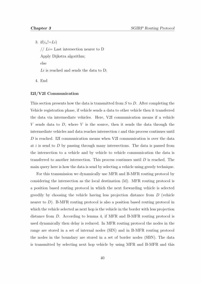
I2I/V2I Communication
This section presents how the data is transmitted from S to D. After completing the
Vehicle registration phase, if vehicle sends a data to other vehicle then it transferred
the data via intermediate vehicles. Here, V2I communication means if a vehicle
V sends data to D, where V is the source, then it sends the data through the
intermediate vehicles and data reaches intersection i and this process continues until
D is reached. I2I communication means when V2I communication is over the data
at i is send to D by passing through many intersections. The data is passed from
the intersection to a vehicle and by vehicle to vehicle communication the data is
transferred to another intersection. This process continues until D is reached. The
main query here is how the data is send by selecting a vehicle using greedy technique.
For this transmission we dynamically use MFR and B-MFR routing protocol by
considering the intersection as the local destination (ld). MFR routing protocol is
a position based routing protocol in which the next forwarding vehicle is selected
greedily by choosing the vehicle having less projection distance from D (vehicle
nearer to D). B-MFR routing protocol is also a position based routing protocol in
which the vehicle selected as next hop is the vehicle in the border with less projection
distance from D. According to lemma 4, if MFR and B-MFR routing protocol is
used dynamically then delay is reduced. In MFR routing protocol the nodes in the
range are stored in a set of internal nodes (SIN) and in B-MFR routing protocol
the nodes in the boundary are stored in a set of border nodes (SBN). The data
is transmitted by selecting next hop vehicle by using MFR and B-MFR and this
40

Chapter 3 SGIRP Routing Protocol
process continues until GN is reached. Figure 3.6 shows how data is transferred
from a vehicle to GN . The algorithm for I2I/V2I is discussed as follows:
Algorithm5 :
1. V creates projections of all NV on line V − CI
// V − CI= line from the initializing vehicle to Current Intersection in
calculated SP
// NV= Neighboring Vehicles
2. S calculates the Euclidean Distance from the projection points to D. Euclidean
Distance (ED) =√(p1 − q1)2 + (p2 − q2)2
// (p1, p2) = projection point of a vehicle and (q1, q2) = CI ′s location
3. Consider the minimum ED of a vehicle V in SBN or SIN
// minimum ED= minimum distance from projection point to CI
4. Send the data to V
5. Continue step 1 to 4 until data is handover to CI
Figure 3.6: MFR and B-MFR Protocol used dynamically
41

Chapter 3 SGIRP Routing Protocol
Forwarding Vehicle Selection Phase
This section presents how GN selects a forwarding vehicle VF after receiving the
data from a vehicle. After GN receives the data from a vehicle V , now its duty
is to select a vehicle in the direction of updated SP . The SP is calculated again
because D′s location is changing with time. As discussed earlier, GN stores the
CV information generated between itself and its neighboring intersections. It first
checks whether there is a CV region in the calculated updated SP and if CV does
not exist it selects VF in that direction. If CV exists, GN again calculates another
SP to D and selects VF . If a SP found is S �i1 �i2 �i3 �D then S only checks
the CV existence between it and i1. Then the main query is how VF is selected.
VF is the first vehicle selected by GN in SP ′s direction which forwards the data
to the next intersection via intermediate vehicles. After finding the direction, GN
calculates a velocity difference vF and the vehicle having less velocity difference is
chosen as the next hop vehicle. In between the intersections government sets an
average vehicle speed α to control accidents. vF is calculated as vF = |α− vi|,
where vi=v1,v2,......,vi is the velocity of a vehicle at the intersection in SP direction.
According to figure 3.7, GN assumes that all vehicles between the intersections i2
and i3 in the city area maintain an average speed. So, it selects that vehicle as VF
in SP direction which has a minimum vF because if vF is maximum and data is
forwarded to that VF then there may be link disruption. In lemma 11, it is proved
that VF is the vehicle with less vF . After selecting the VF , GN checks whether that
vehicle is a genuine vehicle or not by authenticating the vehicle. GN uses algorithm
3, which is discussed earlier to decide whether VF is genuine or not. If it is genuine
it passes the data. By doing this, vehicles in the city area are alerted that they may
be checked at any time and there may be less chance of attacks. Then VF passes the
data to other vehicle and this above process continues until D is reached. Algorithm
6 shows how VF is selected by GN .
Algorithm6 :
1. GN calculates SP
42
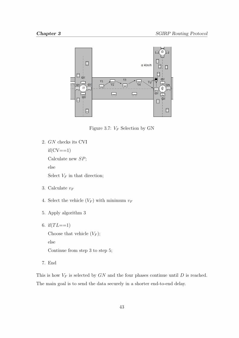
Chapter 3 SGIRP Routing Protocol
Figure 3.7: VF Selection by GN
2. GN checks its CVI
if(CV==1)
Calculate new SP ;
else
Select VF in that direction;
3. Calculate vF
4. Select the vehicle (VF ) with minimum vF
5. Apply algorithm 3
6. if(TL==1)
Choose that vehicle (VF );
else
Continue from step 3 to step 5;
7. End
This is how VF is selected by GN and the four phases continue until D is reached.
The main goal is to send the data securely in a shorter end-to-end delay.
43

Chapter 3 SGIRP Routing Protocol
3.3 Summary
In this chapter, we have described our proposed SGIRP protocol by describing the
four phases used to send the data smoothly from source to the destination. We
have solve the problem of CV region, SP generation and security by using these four
phases. SGIRP protocol provides better services to the end users if it is implemented
practically. in the next chapter we have evaluated our protocol by deriving and
proving the theorems related to the protocol. We have also compared SGIRP with
Gytar in terms of shorter time delay.
44

Chapter 4
Evaluation of SGIRP Routing
Protocol
4.1 Introduction
Evaluation of a protocol is mostly needed for analyzing the correctness of the
protocol. As SGIRP consists of many algorithms, it should be analyzed and proved,
so that we can say that the protocol is working in a well manner. In this chapter,
we have proved the algorithm by proving the lemmas and find solutions for different
problems.
The chapter is presented as follows: section 4.2 shows the evaluation of SGIRP
protocol and section 4.3 shows the summary of the chapter.
4.2 Analysis of SGIRP Protocol
In this section, we have evaluated SGIRP routing protocol by deriving and proving
the theorems related to the protocol. We have also evaluated that SGIRP routing
protocol is better than Gytar routing protocol in terms of shorter end-to-end delay.
Before going to the lemmas we discuss about the notations used in our protocol and
45

Chapter 4 Evaluation of SGIRP Routing Protocol
shown in table 4.1.
Table 4.1: Notations and Definitions
Notation Definition
PL Path Length
LD Local Distance
ld local destination
t local time delay from one hop to other
(τt + τo)V1V2 Time delay to send the data from V1 to V2 where τt shows
the transmission delay and τo presents the other delays like
queing delay, propagation delay, processing delay, etc.
α Average Speed set by the government between the
intersections
DNew New position of D
GP Greedy Path chosen by a vehicle to select a next hop
PD Projection distance from a node’s projection point to ld(i)
v velocity of a vehicle
V Vehicle
The theorems related to SGIRP are derived and proved as follows:
Theorem 4.2.1. The SP selected from S to D is the sum of all the intermediate
distances.
Proof. Let the total distance selected from S to D is TD and suppose S sends
data to D by passing through the intermediate intersections {i1, i2, ......, in} where
n = {1, 2, ......, n} and path P is presented as:
P = S → i1 → i2 → ...... → in → D (4.1)
46

Chapter 4 Evaluation of SGIRP Routing Protocol
From equation 4.1,
TD = Si1 + i1i2 + ......+ inD (4.2)
Let LD is the distance from a vehicle (S) to intersection or intersection to
intersection and the set LD consists of elements and equation 4.2 can be written as,
{Si1, i1i2, ......, inD}
Hence, from equation 4.3 it is proved that TD is the sum of all the intermediate
distances.
TD = LD1 + LD2 + ......+ LDn (4.3)
Theorem 4.2.2. Delay increases with increase in the number of hop counts.
Proof. Let path P1 has p number of hops and path P2 has q number of hops, where
p > q and length of the path (PL) are same (PL1=PL2). Here hops are the
intersections between S and D. From equation 1 and 2, PL1 = S → i1 → i2 →
...... → ip → D and PL2 = S → i1 → i2 → ...... → iq → D and PL for P1 and P2 is
presented as:
PL1 = Si1 + i1i2 + i2i3 + ......+ ipD =
p∑p=1
LDp (4.4)
PL2 = Si1 + i1i2 + i2i3 + ......+ iqD =
p∑p=1
LDq (4.5)
Let T1 and T2 are the time delays in P1 and P2 respectively to send the data packet
from S to D and it is presented as:
T1 = (τt + τo)Si1+(τt + τo)i1i2+......+(τt + τo)ipD = t1+t2+......+tp =
p∑p=1
tp (4.6)
T2 = (τt + τo)Si1+(τt + τo)i1i2+......+(τt + τo)iqD = t1+t2+......+tq =
q∑q=1
tq (4.7)
As , from equation 4.6 and 4.7, T1 > T2 and hence, if number of hops increases time
delay increases.
47

Chapter 4 Evaluation of SGIRP Routing Protocol
Theorem 4.2.3. Intersection i become an ld when MFR and B-MFR routing
Protocol is used.
Proof. By using SP algorithm let path P = S → i1 → i2 → ...... → in → D and as
proved in theorem 4.0.1 TD =∑n
n=1 LDn. But LD consists of many greedy paths
GPs chosen by the vehicles between the intersections.
Let LD is a set of GPs {GPi1V1 , GPV1V2 , ......, GPVni2} from i1 to i2 where
{V1, V2, ......, Vn} are the vehicles which participated in routing between i1 and i2.
LD = GPi1V1 +GPV1V2 + ......+GPVni2 =∑
GP (4.8)
GP is selected by applying MFR and B-MFR routing protocol dynamically by
considering i2 as the ld by calculating the ED and the projections on lines
{i1i2, V1i2, ......, Vni2}. Hence, i become a local destination to the vehicles inside
i1 and i2 while selecting the greedy paths.
Theorem 4.2.4. Delay is reduced if MFR and B-MFR routing protocol is used
dynamically.
Proof. According to MFR and B-MFR routing protocol, if a vehicle having
maximum PD from the initializing vehicle then it is chosen as the next hop to
send the data. In figure 4.1 it is shown that PD is the distance from V1 to i. Let,
in first case S chooses V1 in figure 4.1 to send the data and it continues by choosing
path P = S → V1 → V2 → V3 and it takes T1 delay. In second case, S chooses V3
directly to send the data by using B-MFR protocol and it takes T2 delay.
� Case 1: As P = S → V1 → V2 → V3 , according to theorem 4.0.2 if number
of hops increase delay also increases. So, T1 is presented as:
T1 = (τt + τo)SV1+ (τt + τo)V1V2
+ (τt + τo)V2V3(4.9)
� Case 2: AS P = S → V3, T2 is presented as:
T1 = (τt + τo)SV3(4.10)
48
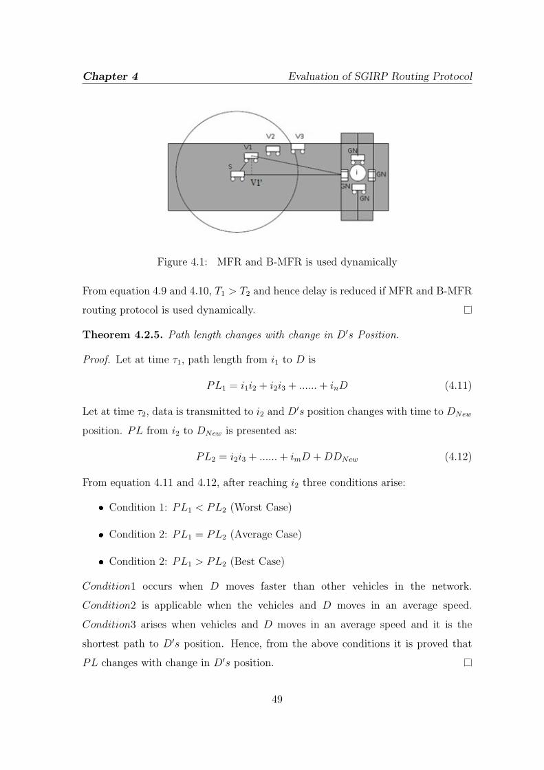
Chapter 4 Evaluation of SGIRP Routing Protocol
Figure 4.1: MFR and B-MFR is used dynamically
From equation 4.9 and 4.10, T1 > T2 and hence delay is reduced if MFR and B-MFR
routing protocol is used dynamically.
Theorem 4.2.5. Path length changes with change in D′s Position.
Proof. Let at time τ1, path length from i1 to D is
PL1 = i1i2 + i2i3 + ......+ inD (4.11)
Let at time τ2, data is transmitted to i2 and D′s position changes with time to DNew
position. PL from i2 to DNew is presented as:
PL2 = i2i3 + ......+ imD +DDNew (4.12)
From equation 4.11 and 4.12, after reaching i2 three conditions arise:
� Condition 1: PL1 < PL2 (Worst Case)
� Condition 2: PL1 = PL2 (Average Case)
� Condition 2: PL1 > PL2 (Best Case)
Condition1 occurs when D moves faster than other vehicles in the network.
Condition2 is applicable when the vehicles and D moves in an average speed.
Condition3 arises when vehicles and D moves in an average speed and it is the
shortest path to D′s position. Hence, from the above conditions it is proved that
PL changes with change in D′s position.
49

Chapter 4 Evaluation of SGIRP Routing Protocol
Theorem 4.2.6. Hop count changes with change in D′s position.
Proof. From theorem 4.0.5, let at τ1 time, PL from i1 toD is PL1 = i1i2+i2i3+......+
inD and at time τ1, data is transmitted to i2 and D′s position changes with time
to DNew. Path length from i2 to DNew is PL2 = i1i2 + i2i3 + ......+ imD +DDNew.
Suppose PL1 has p hops and PL2 has q hops, then by considering condition 1,
condition 2 and condition 3 from theorem 4.0.5, we get three inferences:
Inference=
p < q
p > q
p = q
Hence, from the inferences we conclude that as position of D is changing the hop
count also changes.
Theorem 4.2.7. Position of D should be updated else delay increases.
Proof. From theorem 4.0.5 and theorem 4.0.6 we know that path length PL changes
with change in dues position and hop count has also changed with changes in D′s
position respectively. Let the PL selected from S to D is,
PL1 = Si1 + i1i2 + ......+ imD (4.13)
and PL selected from intermediate in is,
PL2 = inin+1 + in+1in+2 + ......+ in+pD (4.14)
D′s position is not updated in equation 4.14 after changing the position from S to
in. Let D has changed its location from D to DNew, but when data reached in+p
position it searches for D because D′s position is not updated and uses location
service protocol to search DNew and it may increase the delay.
But may be at some intersection in+p−1 where n = {1, 2, ......, n} and p =
{1, 2, ......, p} DNew may be closer if position of D is updated. So, let PL3 is the
updated path length from in+p−1,
PL3 = in+p−1DNew (4.15)
50

Chapter 4 Evaluation of SGIRP Routing Protocol
So, from equation 4.14 and 4.15, PL3 < PL2 and let PL2 takes T2 delay to transmit
the data and PL3 takes T3 delay to transmit the data.
T2 = (τt + τo)inin+1+ (τt + τo)in+1in+2
+ ......+ (τt + τo)in+pD(4.16)
T3 = (τt + τo)in+p−1DNew(4.17)
According to theorem 4.0.3, number of hops of PL3 is less than the number of hops
of PL2, from equation 4.16 and 4.17 hence T3 < T2.
Theorem 4.2.8. If degree of intersection is more, then number of decisions to select
a SP will be more.
Proof. Let i1 and i2 are two intersections having degrees m and n respectively. Let
m < n and GN in i1 can take m number of decisions and GN in i2 can take n
number of decisions. Let decision d1 in i1 is d1 = {i1i2, i1i3, ......, i1im} and in i2
d2 = {i1i2, i1i3, ......, i1in} where i1i2 is the decision by GN from i1 to i2. Suppose,
probability of selecting a SP is P and probability of not selecting a SP is (1 − P )
then according to d1 and d2, as m < n probability to select a SP is more. Hence,P >
(1− P ).
Theorem 4.2.9. If vehicle V1 is unable to communicate with vehicle V2 then CV is
generated in that region.
Proof. Let range of V1 is R1 and the range of V2 is R2 and R1=R2. From figure 3,
we know that vehicle V1 is unable to communicate with vehicle V2 and the shaded
portion shows the CV region.
Let the area of the CV region is ACV , where
ACV = w ∗ x (4.18)
Where R1 < x and R2 < x If the area of total road segment is A and it consists of
n vehicles {V1, V2, ......, Vn} and ACV has null vehicles, then from equation 4.18,
A ∩ ACV = Φ (4.19)
The conditions for no void regions are,
51

Chapter 4 Evaluation of SGIRP Routing Protocol
� Condition 1: x ≤ R1
� Condition 2: x-R1= -ve
� Condition 3: x-R1= 0
If any of the three conditions arises, then no void region exists in that area else CV
region exists.
Theorem 4.2.10. If CV exists then delay increases with ”carry and forward”
mechanism in Gytar.
Proof. Let the path length selected by Gytar is PLGytar and path length selected
by SGIRP is PLSGIRP and let PLGytar=PLSGIRP . So, from figure 4.2 PLGytar and
PLSGIRP are presented as:
Figure 4.2: PL for Gytar and SGIRP
PLSGIRP = i1i2 + i2i3 (4.20)
PLGytar = i1i4 + i4i3 (4.21)
As we know, SGIRP has knowledge K about the CV and it selected path i1 → i2 →
i3 , but Gytar has no past knowledge K about the CV and if a vehicle encounters
a CV then ”carry and forward” mechanism is executed to recover the hole. The
vehicle carries the data until it encounters a vehicle in its range. This mechanism
may increase the delay.
52

Chapter 4 Evaluation of SGIRP Routing Protocol
Let there are p number of vehicles where between i1-i2 where p = {1, 2, 3, ......, p}
and q number of vehicles between i1-i4 and suppose p < q and path q =
{1, 2, 3, ......, q} suffers from CV region generation then the path taken by Gytar
will increase the time delay.
Let, T1 is the delay to send the data from i1 to i2 by SGIRP, T2 is the delay to
send the data from i2 to i4 by Gytar and c is the time to carry the data in Gytar.
So, the time delays for SGIRP and Gytar are presented as:
T1 = (τt + τo)i1V1+ (τt + τo)V1V2
+ ......+ (τt + τo)Vpi2(4.22)
T2 = (τt + τo)i1V1+ (τt + τo)V1V2
+
carry and forward︷ ︸︸ ︷τC + (τt + τo)V2V3
+ ......+ (τt + τo)Vpi2(4.23)
Where, {V1, V2, ......, Vp} are the vehicles and τC is time to carry the data by a vehicle
until it encounters a new vehicle and τC may occur many number of times. So, it is
proved that SGIRP takes less delay than Gytar and hence, T1 < T2.
Theorem 4.2.11. VF is the vehicle with less velocity difference vF .
Proof. As we know, VAvg =∑
vPp
and velocity difference is calculated as vF = |α− vp|
and the vehicle with less vF is selected as the forwarding vehicle.As we know,
and velocity difference is calculated as and the vehicle with less is selected as the
forwarding vehicle.
Let, there are p number of moving vehicles between i1 and i2 with velocities
{v1, v2, ......, vp} then average is calculated as:
vAvg =v1+v2+......+vp
p
=∑
vpp
But we assume that vAvg from one intersection to other is a constant α set
by the government. So, vAvg calculated is nearly equal to α and hence, vAvg=α .
Let, velocities of q vehicles at the intersection are {v1, v2, ......, vq} and the velocity
difference vF is calculated for each vehicle at an intersection as:
vF = |α− vq| (4.24)
53

Chapter 4 Evaluation of SGIRP Routing Protocol
Then the velocities vF ′s are calculated and sorted in increasing order. VF is selected
as the vehicle having lowest velocity difference . Let two conditions arise from this,
� Condition1 : vF >> α
� Condition2 : vF << α
if these two conditions arise then there is a chance of link failure. So, VF is the
vehicle with less vF .
Theorem 4.2.12. A vehicle V is a malicious node if it fails to pass the vehicle
authentication test.
Proof. Let V is a vehicle and wants to claim its identity to GN who is a verifier at
the intersection. If GN wants to verify the identity of V then it challenges V by
sending C. V sends its KN |in to GN for verification. In this procedure V is the
claimant and GN is the verifier. The authentication test is shown as follows:
GNC→ V
VKN |in→ GN
After obtaining KN , GN checks it by decrypting KN to Decrypted Key (DK)
and matches it with the Stored key (Skey) and generates Trust Levels 0 and 1.
TL=
1 ifSkey = DK
0 ifSkey ̸= DK
If TL = 1 then V is a genuine node else it is a malicious node and TL = 0.
Theorem 4.2.13. If GN handovers the data to a malicious vehicle then delay
increases.
Proof. Let the data is transferred to a malicious vehicle VF , then according to
theorem 4.0.10 it can increase the τC time (malicious vehicle can hold the data
for τC time and it can perform selective forwarding). Suppose sending data from VF
to V1 takes T1 delay and if VF is a malicious vehicle it takes T2 delay,
T1 = (τt + τ)VFV1(4.25)
54

Chapter 4 Evaluation of SGIRP Routing Protocol
T2 = τC + (τt + τ)VFV1(4.26)
Hence, from equation 4.25 and 4.26, T2 > T1 and if VF is a malicious vehicle it
increases the delay.
Theorem 4.2.14. Once authenticating in SGIRP reduces the authentication
overhead.
Proof. According to SGIRP protocol, a vehicle authenticates itself in a monthly
basis or half yearly basis by renewing its KN | in.
Let, authentication test is performed at every intersection {i1, i2, ......, in} ∀ x where
x={V1, V2, ......, Vn}, and if this happens it increases the authentication overhead. If
vehicles authenticate themselves at every intersection then,
{V1, V2, ......, Vn}Authentication→ i1
{V1, V2, ......, Vn}Authentication→ i2
.
.
.
{V1, V2, ......, Vn}Authentication→ in
if n number of intersections are there then a vehicle is authenticated n number of
times while passing through a intersection i and authentication overhead is more at
every intersection. But in SGIRP, at the time of routing only it checks VF and sends
the data. As discussed earlier, vehicles in SGIRP are assumed to be genuine and
the vehicles authentication can be performed at any time. A vehicle authenticates
itself in a monthly basis or half yearly basis by renewing its KN | in. This procedure
reduces the authentication overhead in SGIRP.
Theorem 4.2.15. If number of lanes increases then there is a less chance of CV
region generation.
Proof. Let, two intersections i1 and i2 are connected with L is presented as
{V1, V2, ......Vn}. Suppose i1 and i2 are connected with a single lane road shown
55

Chapter 4 Evaluation of SGIRP Routing Protocol
in figure 4.3 with a CV region. But in figure 4.4 there is chance of CV region
generation but it is recovered by the vehicles in other lanes. Let in figure 4.3 there
are n number of vehicles in a single lane L1 and if a CV region is generated in the
region R1=w ∗ x then a vehicle is unable to communicate with another vehicle. Let
Figure 4.3: Single Lane with CV
another figure 4.4 consists of a multilane path where there are three lanes L1, L2
and L3 and if a CV region is generated in region R2=z ∗ y at L1 lane then the
vehicles recover from this situation by communicating with the next lane vehicles
and transmit the data to the intersection. Suppose P (m) is the probability of getting
Figure 4.4: Multi-Lane with CV
m number of vehicles in a region. According to Poisson distribution the probability
56

Chapter 4 Evaluation of SGIRP Routing Protocol
of getting m number of vehicles is shown as,
p(m) =(λA1)
m
m!e−λA1 (4.27)
Where, A1 = πr2
2and λ = density (number of vehicles per (Km)2) According to
figure 4.3, in region A1 there are m = 0 number of vehicles, so from equation 4.27:
p(m1) = 0 (4.28)
In this scenario, we have considered only half of the area of the vehicles range because
the vehicle is moving in the forward direction and it searches for a vehicle in the
same direction.
According to figure 4.4, let in the region A2 there is m number of vehicles where,
m=0+p+q
=p+q
0= number of vehicles in lane L1 in vehicles (V1) range
p= number of vehicles in lane L2 in vehicles (V1) range
q= number of vehicles in lane L3 in vehicles (V1) range
So, from equation 4.27,
p(m2) =(λA2)
p+q
(p+ q)!e−λA2 (4.29)
Hence, from equation 4.28 and 4.29, if P (m2) > P (m1) then there is a less chance
of CV region generation.
Theorem 4.2.16. CV reduces network performance.
Proof. According to theorem 4.0.10, if CV region exists then delay increases. As we
know, end-to-end delay is a robust parameter for measuring network performance
and if end-to-end delay increases, network performance degrades. By considering
Gytar protocol, delay T increases with carry and forward mechanism. The packet
may be dropped by the vehicle if it is unable to find a vehicle in forward direction.
The time delay for searching a vehicle increases and this may lead to high end-to-end
Delay. Let, Total Delay (TD) to send a message from S to D is shown as follows if
57

Chapter 4 Evaluation of SGIRP Routing Protocol
CV exists in the path S → i1 → i2 → ...... → in → D then,
TD = (τt + τO)Si1 + (τt + τO)i1i2 + ......+ (τt + τO)inD
=
(τt + τO)SV1 + (τt + τO)V1V2 +
carry and forward︷ ︸︸ ︷τC + (τt + τO)V2V3 + ......+ (τt + τO)Vpi1
Si1
+
(τt + τO)i1V1 + (τt + τO)V1V2 +
carry and forward︷ ︸︸ ︷τC + (τt + τO)V2V3 + ......+ (τt + τO)Vqi2
i1i2
+ ......+
(τt + τO)inV1 + (τt + τO)V1V2 +
carry and forward︷ ︸︸ ︷τC + (τt + τO)V2V3 + ......+ (τt + τO)VrD
inD
=t1 + t2 + ......+ tn
=n∑
n=1
tn (4.30)
As we know, from theorem 4.0.10 if there exists a number of CVs in the path
P=S → i1 → i2 → ...... → in → D, TD increases and network performance
decreases.
4.3 Summary
In this chapter, we have evaluated SGIRP routing protocol by deriving and proving
the theorems related to the protocol. We have also evaluated that SGIRP routing
protocol shows better performance than Gytar routing protocol in terms of shorter
end-to-end delay. As it is a pure mathematical model the theorems are proved and
SGIRP protocol is evaluated completely.
58

Chapter 5
Conclusion
5.1 Conclusion
SGIRP routing protocol sends the data to the destination in a fast and secure
manner. This routing protocol can provide better ITS services to the passengers
as well as drivers. The end users can be benefited with applications like media
downloading, sending alert messages to other vehicles, e-marketing, etc. These
applications are performed in a secure way by which the data are protected from
the malicious users. As SGIRP uses SP algorithm to reach D by using GPS services
it reduces the delay by selecting an optimal path. It also recovers from sparse
regions by having a past knowledge about the regions and selects a sparse free
path. It also checks the malicious attacks by using the GN which authenticates the
vehicle. As vehicles are authenticated at any time the vehicles moves in the city
area with their encrypted key KN |in. It is also evaluated that SGIRP shows better
routing performance than Gytar in terms of shorter end-to-end delay. The theoremss
discussed above are proven and it evaluates SGIRP performance in a realistic way.
59

Chapter 5 Conclusion
5.2 Scope for Further Research
In future this algorithm is expanded by adding the concepts of traffic lights to control
road traffic and congestion. The delay in sending the data can be reduced by finding
new solutions for communication void problem and optimal path problem. Image
processing techniques can also be used to track persons on roads (catching terroists).
60
Bibliography
[1] Fan Li and Yu Wang. Routing in vehicular ad hoc networks: A survey. Vehicular Technology
Magazine, IEEE, 2(2):12–22, 2007.
[2] T. Leinmuller, E. Schoch, and F. Kargl. Position verification approaches for vehicular ad hoc
networks. Wireless Communications, IEEE, 13(5):16–21, 2006.
[3] Sherali Zeadally, Ray Hunt, Yuh-Shyan Chen, Angela Irwin, and Aamir Hassan. Vehicular
ad hoc networks (vanets): status, results, and challenges. Telecommunication Systems,
50(4):217–241, 2012.
[4] J. Harri, F. Filali, and C. Bonnet. Mobility models for vehicular ad hoc networks: a survey
and taxonomy. Communications Surveys Tutorials, IEEE, 11(4):19–41, 2009.
[5] H. Hartenstein and K.P. Laberteaux. A tutorial survey on vehicular ad hoc networks.
Communications Magazine, IEEE, 46(6):164–171, 2008.
[6] Kharat M. U. Nagaraj, U. and P. Dhamal. Study of various routing protocols in vanet. IJCST,
2(4):45–52, 2011.
[7] M. Mauve, J. Widmer, and H. Hartenstein. A survey on position-based routing in mobile ad
hoc networks. Network, IEEE, 15(6):30–39, 2001.
[8] I. Stojmenovic. Position-based routing in ad hoc networks. Communications Magazine, IEEE,
40(7):128–134, 2002.
[9] Fubler H. KieB, W. and H. Widmer. Hierarchical location service for mobile ad-hoc networks.
SIGMOBILE Mob. Comput. Commun. Rev., 8(4):47–58, October 2004.
[10] Fler H. Hartenstein H. Ksemann, M. and M. Mauve. A reactive location service for mobile ad
hoc networks. Technical Report 14, Univ.Mannheim, Mannheim, Germany, Nov. 2002 2002.
[11] X. Jiang and T. Camp. An efficient location server for an ad hoc networks. Technical Report
MCS-03-06, Colorado School Mines, May 2003.
61

Bibliography
[12] Jinyang Li, John Jannotti, Douglas S. J. De Couto, David R. Karger, and Robert Morris.
A scalable location service for geographic ad hoc routing. In Proceedings of the 6th annual
international conference on Mobile computing and networking, MobiCom ’00, pages 120–130,
New York, NY, USA, 2000. ACM.
[13] Christian Lochert, Holger Mauve, Martin, and Hannes Hartenstein. Geographic routing in
city scenarios. SIGMOBILE Mob. Comput. Commun. Rev., 9(1):69–72, January 2005.
[14] Genping Liu, Bu-Sung Lee, Boon-Chong Seet, Chuan-Heng Foh, Kai-Juan Wong, and
Keok-Kee Lee. A routing strategy for metropolis vehicular communications. In Hyun-Kook
Kahng and Shigeki Goto, editors, Information Networking. Networking Technologies for
Broadband and Mobile Networks, volume 3090 of Lecture Notes in Computer Science, pages
134–143. Springer Berlin Heidelberg, 2004.
[15] M. Jerbi, S. M Senouci, T. Rasheed, and Y. Ghamri-Doudane. Towards efficient geographic
routing in urban vehicular networks. Vehicular Technology, IEEE Transactions on,
58(9):5048–5059, 2009.
[16] Brad Karp and H. T. Kung. Gpsr: greedy perimeter stateless routing for wireless networks. In
Proceedings of the 6th annual international conference on Mobile computing and networking,
MobiCom ’00, pages 243–254, New York, NY, USA, 2000. ACM.
[17] R.S. Raw and D. K. Lobiyal. B-mfr routing protocol for vehicular ad hoc networks. In
Networking and Information Technology (ICNIT), 2010 International Conference on, pages
420–423, 2010.
[18] R. S. Raw and S. Das. Performance comparison of position-based routing protocols in
vehicle-to-vehicle (v2v) communication. International Journal of Engineering Science and
Technology, 3(1), January 2011.
[19] P.K. Sahu, E.H.-K. Wu, J. Sahoo, and M. Gerla. Bahg: Back-bone-assisted hop greedy
routing for vanet’s city environments. Intelligent Transportation Systems, IEEE Transactions
on, 14(1):199–213, 2013.
[20] T. Taleb, E. Sakhaee, A. Jamalipour, K. Hashimoto, N. Kato, and Y. Nemoto. A stable routing
protocol to support its services in vanet networks. Vehicular Technology, IEEE Transactions
on, 56(6):3337–3347, 2007.
[21] B. A. Forouzan and D. Mukhopadhyay. Cryptography and Network Security. Tata
McGraw-Hill, 2nd edition, 2011.
[22] Gongjun Yan, S. Olariu, and M.C. Weigle. Providing location security in vehicular ad hoc
networks. Wireless Communications, IEEE, 16(6):48–55, 2009.
62
Bibliography
[23] S.K. Bhoi and P.M. Khilar. Sst: A secure fault-tolerant smart transportation system for
vehicular ad hoc network. In Parallel Distributed and Grid Computing (PDGC), 2012 2nd
IEEE International Conference on, pages 545–550, 2012.
[24] S.K. Bhoi, I.H. Faruk, and P.M. Khilar. Csrp: A centralized secure routing protocol for mobile
ad hoc network. In Emerging Applications of Information Technology (EAIT), 2012 Third
International Conference on, pages 429–432, 2012.
[25] K. Sampigethaya, Mingyan Li, Leping Huang, and R. Poovendran. Amoeba: Robust
location privacy scheme for vanet. Selected Areas in Communications, IEEE Journal on,
25(8):1569–1589, 2007.
[26] Xiaonan Liu, Zhiyi Fang, and Lijun Shi. Securing vehicular ad hoc networks. In Pervasive
Computing and Applications, 2007. ICPCA 2007. 2nd International Conference on, pages
424–429, 2007.
[27] T. Leinmuller, E. Schoch, and C. Maihofer. Security requirements and solution concepts in
vehicular ad hoc networks. In Wireless on Demand Network Systems and Services, 2007.
WONS ’07. Fourth Annual Conference on, pages 84–91, 2007.
[28] Gonzlez-Tablas A. I. Fuentes, J. M. and A. Ribagorda. verview of security issues in vehicular
ad-hoc networks. IGI Global, 2011.
[29] J. T. Isaac, S. Zeadally, and J.S. Camara. Security attacks and solutions for vehicular ad hoc
networks. Communications, IET, 4(7):894–903, 2010.
63

Dissemination
Dissemination
Journal
1. Sourav Kumar Bhoi and Pabitra Mohan Khilar, Vehicular Communication: A Survey, IET
Networks, 2013 (Communicated)
2. Sourav Kumar Bhoi and Pabitra Mohan Khilar, SGIRP: A Secure and Greedy Intersection
Based Routing Protocol for VANET using Guarding Nodes, IET Networks, 2013
(Communicated)
Conference
1. Sourav Kumar Bhoi and Pabitra Mohan Khilar, CSRP: A Centralized Secure Routing
protocol For MANET, The Third IEEE International Conference on Emerging Applications
in Information Technology, pp. 429-432, December 2012
2. Sourav Kumar Bhoi and Pabitra Mohan Khilar, SST: Secure Fault-Tolerant Smart
Transportation System for Vehicular Ad Hoc Network, The Second IEEE International
Conference on Parallel, Distributed and Grid Computing, pp. 556-561, December 2012
3. Sourav Kumar Bhoi and Pabitra Mohan Khilar, A Secure Routing Protocol for Vehicular Ad
Hoc Network to Provide ITS Services, IEEE International Conference on Communication
and Signal Processing, Tamilnadu, April 4-6, 2013
64