Embed Size (px)
Citation preview
506099−01
�����������04/09
�������
SGA036, 060,120, 240, AND
SGB288
©2008 Lennox Industries Inc.
Litho U.S.A.
506099−014/2009Supersedes 4/2008
WHAT TO DO IF YOU SMELL GAS:
Do not store or use gasoline or otherflammable vapors and liquids in thevicinity of this or any other appliance.
Installation and service must be per-formed by a qualified installer, ser-vice agency or the gas supplier.
� Do not try to light any appliance.
� Do not touch any electrical switch; do notuse any phone in your building.
� Immediately call your gas supplier from aneighbor’s phone. Follow the gas suppli-er’s instructions.
� If you cannot reach your gas supplier, callthe fire department.
Dallas, Texas
� Extinguish any open flames.
ROOFTOPUNITS
READ ALL INSTRUCTIONS IN THIS MANUALAND RETAIN FOR FUTURE REFERENCE
SGA240 (20−TON) &SGB288 (24−TON)
WARNINGImproper installation, adjustment, alteration, ser-vice or maintenance can cause property damage,personal injury or loss of life. Installation and ser-vice must be performed by a qualified installer, ser-vice agency or the gas supplier
� Leave the building immediately.
FIRE OR EXPLOSION HAZARD
Failure to follow safety warnings ex-actly could result in serious injurydeath or property damage.
WARNING
SGA120 (10−TON)
LENOXN
LENOXNLENOXN
LENOXNLENOXN
Page 1
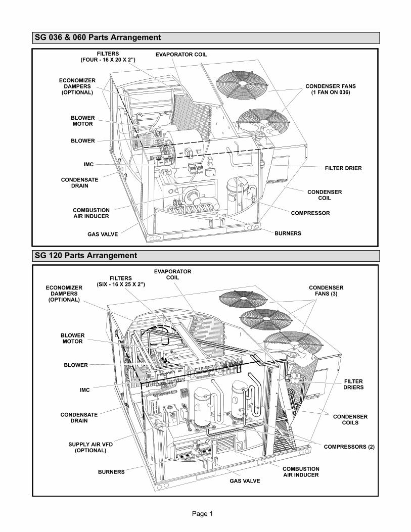
SG 036 & 060 Parts Arrangement
COMBUSTIONAIR INDUCER
EVAPORATOR COIL
BLOWERMOTOR
CONDENSER FANS(1 FAN ON 036)
CONDENSERCOIL
COMPRESSOR
GAS VALVE
BLOWER
CONDENSATEDRAIN
FILTERS(FOUR − 16 X 20 X 2")
ECONOMIZERDAMPERS
(OPTIONAL)
BURNERS
FILTER DRIER
LLENOXN
LENOXN
IMC
SG 120 Parts Arrangement
LENOXN
LENOXN
LENOXN
LENOXN
COMBUSTIONAIR INDUCER
EVAPORATORCOIL
BLOWERMOTOR
CONDENSERFANS (3)
CONDENSERCOILS
COMPRESSORS (2)
BURNERS
GAS VALVE
CONDENSATEDRAIN
FILTERS(SIX − 16 X 25 X 2")
ECONOMIZERDAMPERS
(OPTIONAL)
IMC
FILTERDRIERS
SUPPLY AIR VFD(OPTIONAL)
BLOWER
Page 2
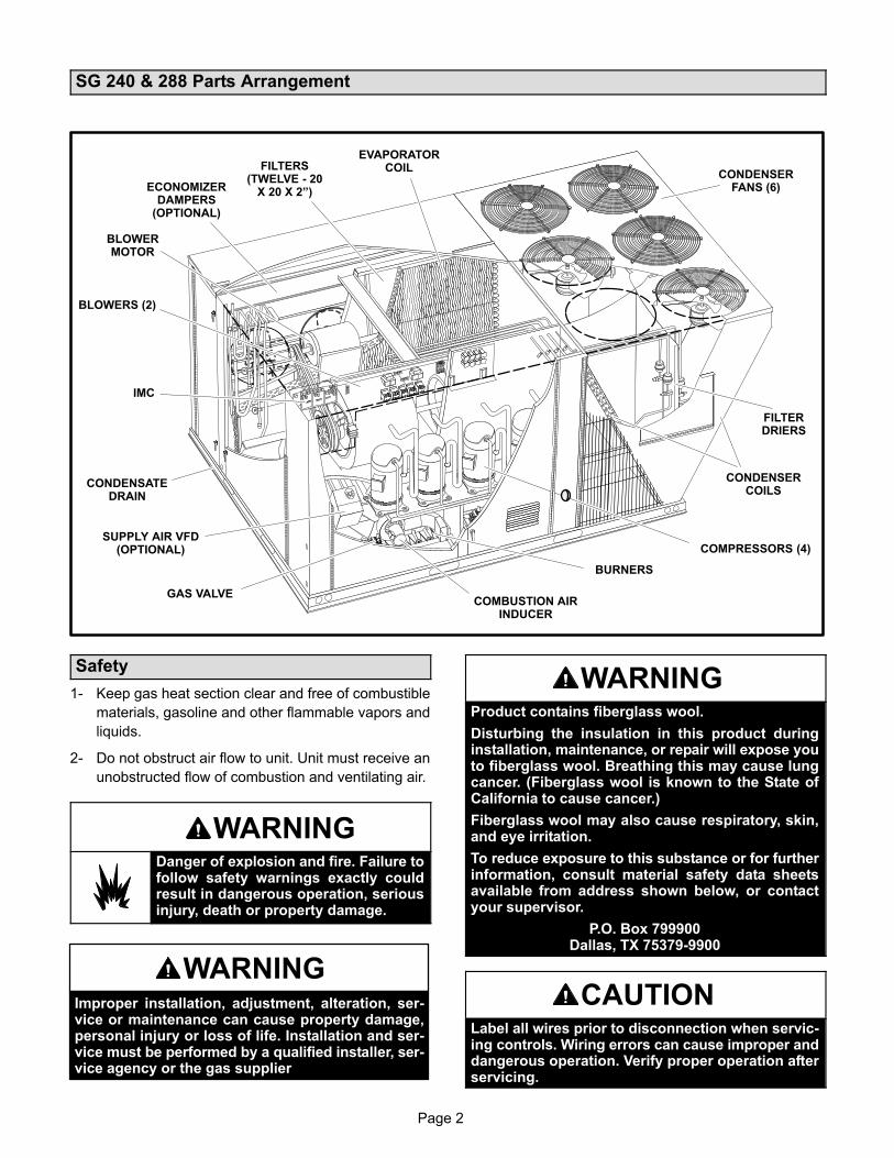
SG 240 & 288 Parts Arrangement
COMBUSTION AIRINDUCER
EVAPORATORCOIL
BLOWERMOTOR
CONDENSERFANS (6)
CONDENSERCOILS
COMPRESSORS (4)
BURNERS
GAS VALVE
BLOWERS (2)
CONDENSATEDRAIN
FILTERS(TWELVE − 20
X 20 X 2")ECONOMIZERDAMPERS
(OPTIONAL)
IMC
SUPPLY AIR VFD(OPTIONAL)
FILTERDRIERS
LENOXN
Safety
1− Keep gas heat section clear and free of combustible
materials, gasoline and other flammable vapors and
liquids.
2− Do not obstruct air flow to unit. Unit must receive an
unobstructed flow of combustion and ventilating air.
WARNINGDanger of explosion and fire. Failure tofollow safety warnings exactly couldresult in dangerous operation, seriousinjury, death or property damage.
WARNINGImproper installation, adjustment, alteration, ser-vice or maintenance can cause property damage,personal injury or loss of life. Installation and ser-vice must be performed by a qualified installer, ser-vice agency or the gas supplier
WARNINGProduct contains fiberglass wool.
Disturbing the insulation in this product duringinstallation, maintenance, or repair will expose youto fiberglass wool. Breathing this may cause lungcancer. (Fiberglass wool is known to the State ofCalifornia to cause cancer.)
Fiberglass wool may also cause respiratory, skin,and eye irritation.
To reduce exposure to this substance or for furtherinformation, consult material safety data sheetsavailable from address shown below, or contactyour supervisor.
P.O. Box 799900Dallas, TX 75379−9900
CAUTIONLabel all wires prior to disconnection when servic-ing controls. Wiring errors can cause improper anddangerous operation. Verify proper operation afterservicing.
Page 3
WARNINGElectric shock hazard. Can causeinjury or death. Before attempting toperform any service or maintenance,turn the electrical power to unit OFF atdisconnect switch(es). Unit may havemultiple power supplies.
WARNINGDanger of electrical shock, explosionand fire. Improper servicing couldresult in dangerous operation, seriousinjury, death or property damage.
WARNINGDo not use this furnace if any part has been underwater. A flood−damaged furnace is extremely dan-gerous. Attempts to use the furnace can result infire or explosion. A qualified service agencyshould be contacted to inspect the furnace and toreplace all gas controls, control system parts,electrical parts that have been wet or the furnaceif deemed necessary.
WARNINGDanger of explosion. Can cause injuryor product or property damage. Shouldthe gas supply fail to shut off or ifoverheating occurs, shut off the gasvalve to the furnace before shutting offthe electrical supply.
WARNINGSMOKE POTENTIAL
The heat exchanger in this unit could be a source ofsmoke on initial firing. Take precautions with re-spect to building occupants and property. Vent ini-tial supply air outside when possible.
Unit Operation
FOR YOUR SAFETY READ BEFORE LIGHTING
BEFORE LIGHTING smell all around the furnace area for
gas. Be sure to smell next to the floor because some gas
is heavier than air and will settle on the floor.
Use only your hand to push in or turn the gas control knob.
Never use tools. If the knob will not push in or turn by
hand, do not try to repair it, call a qualified service
technician. Force or attempted repair may result in a fire
or explosion.
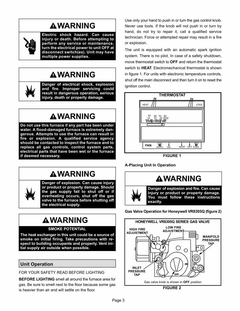
The unit is equipped with an automatic spark ignition
system. There is no pilot. In case of a safety shutdown,
move thermostat switch to OFF and return the thermostat
switch to HEAT. Electromechanical thermostat is shown
in figure 1. For units with electronic temperature controls,
shut off the main disconnect and then turn it on to reset the
ignition control.
THERMOSTAT
FIGURE 1
HEAT COOL
FAN
50 60 70 8010 15 20 2530
HEAT OFF COOLAUTO ON
A−Placing Unit In Operation
WARNINGDanger of explosion and fire. Can causeinjury or product or property damage.You must follow these instructionsexactly.
Gas Valve Operation for Honeywell VR8305Q (figure 2)
HONEYWELL VR8305Q SERIES GAS VALVE
Gas valve knob is shown in OFF position.
FIGURE 2
LOW FIREADJUSTMENT
HIGH FIREADJUSTMENT
INLETPRESSURE
TAP
MANIFOLDPRESSURE
TAP
Page 4
1− Set thermostat to lowest setting.
2− Turn off all electrical power to furnace.
3− This furnace is equipped with an ignition device which
automatically lights the burner. Do not try to light the
burner by hand.
4− Open or remove the heat section access panel.
5− Turn the knob on the gas valve clockwise to
�OFF". Do not force.
6− Wait five (5) minutes to clear out any gas. If you then
smell gas, STOP! Immediately call your
gas supplier from a neighbor’s phone. Follow the gas
supplier’s instructions. If you do not smell gas, go to
the next step.
7− Turn the knob on the gas valve counterclockwise
to �ON". Do not force.
8− Close or replace the heat section access panel.
9− Turn on all electrical power to furnace.
10− Set thermostat to desired setting.
11− The ignition sequence will start.
12− If the furnace does not light the first time (gas line not
fully purged), it will attempt up to two more ignitions
before locking out.
13− If lockout occurs, repeat steps 1 through 10.
14− If the furnace will not operate, follow the instructions
�Turning Off Gas to Furnace" and call your service
technician or gas supplier.
Turning Off Gas to Furnace
1− If using an electromechanical thermostat, set to the
lowest setting.
2− Before performing any service, turn off all electrical
power to the furnace.
3− Open or remove the heat section access panel.
4− Turn the knob on the gas valve clockwise to
�OFF". Do not force.
5− Replace heat section access panel.
WARNINGDanger of explosion. Can cause injury ordeath. Do not attempt to light manually.Unit has a direct spark ignition system.
Burner Flame
WARNINGDanger of explosion and fire. Can causeinjury or product or property damage.Periodically inspect burner flame to en-sure proper unit operation.
The primary air is permanently set for normal operation.
The flame will be basically blue with some clear yellow
streaking in the end of the flame. Inspect burner flame
periodically during heating season using inspection port
provided on the burner access panel.
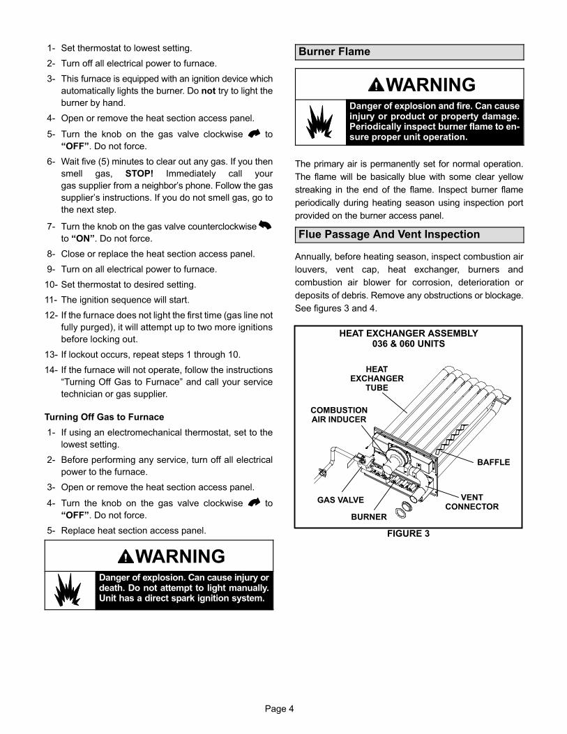
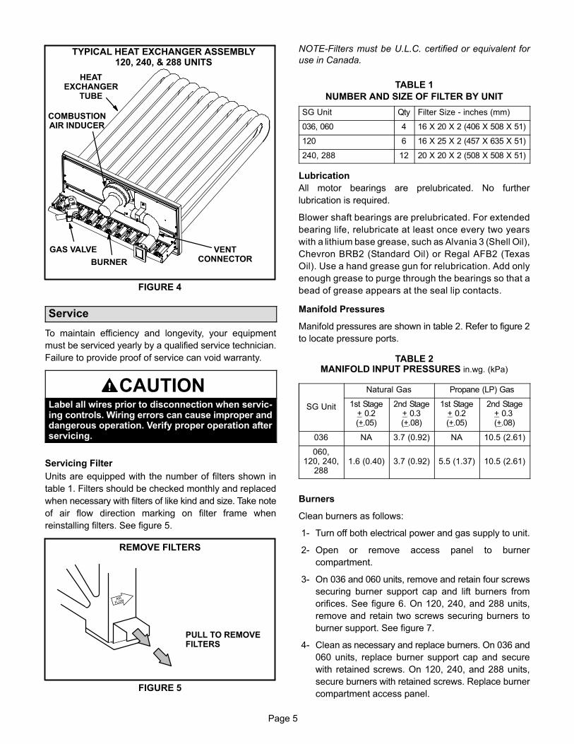
Flue Passage And Vent Inspection
Annually, before heating season, inspect combustion air
louvers, vent cap, heat exchanger, burners and
combustion air blower for corrosion, deterioration or
deposits of debris. Remove any obstructions or blockage.
See figures 3 and 4.
HEAT EXCHANGER ASSEMBLY036 & 060 UNITS
FIGURE 3
BURNER
COMBUSTIONAIR INDUCER
VENTCONNECTOR
GAS VALVE
HEATEXCHANGER
TUBE
BAFFLE
Page 5
TYPICAL HEAT EXCHANGER ASSEMBLY120, 240, & 288 UNITS
FIGURE 4
BURNER
COMBUSTIONAIR INDUCER
VENTCONNECTOR
GAS VALVE
HEATEXCHANGER
TUBE
Service
To maintain efficiency and longevity, your equipment
must be serviced yearly by a qualified service technician.
Failure to provide proof of service can void warranty.
CAUTIONLabel all wires prior to disconnection when servic-ing controls. Wiring errors can cause improper anddangerous operation. Verify proper operation afterservicing.
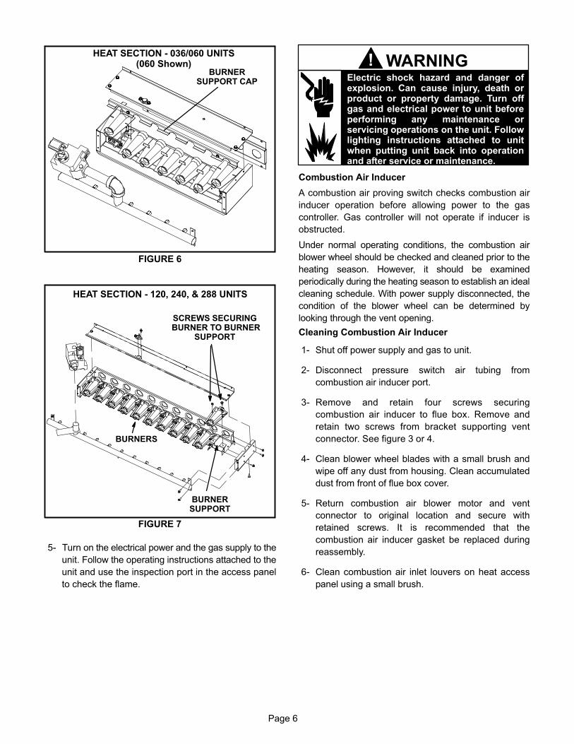
Servicing Filter
Units are equipped with the number of filters shown in
table 1. Filters should be checked monthly and replaced
when necessary with filters of like kind and size. Take note
of air flow direction marking on filter frame when
reinstalling filters. See figure 5.
REMOVE FILTERS
PULL TO REMOVEFILTERS
FIGURE 5
NOTE−Filters must be U.L.C. certified or equivalent for
use in Canada.
TABLE 1
NUMBER AND SIZE OF FILTER BY UNIT
SG Unit Qty Filter Size − inches (mm)
036, 060 4 16 X 20 X 2 (406 X 508 X 51)
120 6 16 X 25 X 2 (457 X 635 X 51)
240, 288 12 20 X 20 X 2 (508 X 508 X 51)
Lubrication
All motor bearings are prelubricated. No further
lubrication is required.
Blower shaft bearings are prelubricated. For extended
bearing life, relubricate at least once every two years
with a lithium base grease, such as Alvania 3 (Shell Oil),
Chevron BRB2 (Standard Oil) or Regal AFB2 (Texas
Oil). Use a hand grease gun for relubrication. Add only
enough grease to purge through the bearings so that a
bead of grease appears at the seal lip contacts.
Manifold Pressures
Manifold pressures are shown in table 2. Refer to figure 2
to locate pressure ports.
TABLE 2MANIFOLD INPUT PRESSURES in.wg. (kPa)
SG Unit
Natural Gas Propane (LP) Gas
1st Stage+ 0.2(+.05)
2nd Stage+ 0.3(+.08)
1st Stage+ 0.2(+.05)
2nd Stage+ 0.3 (+.08)
036 NA 3.7 (0.92) NA 10.5 (2.61)
060,120, 240,
2881.6 (0.40) 3.7 (0.92) 5.5 (1.37) 10.5 (2.61)
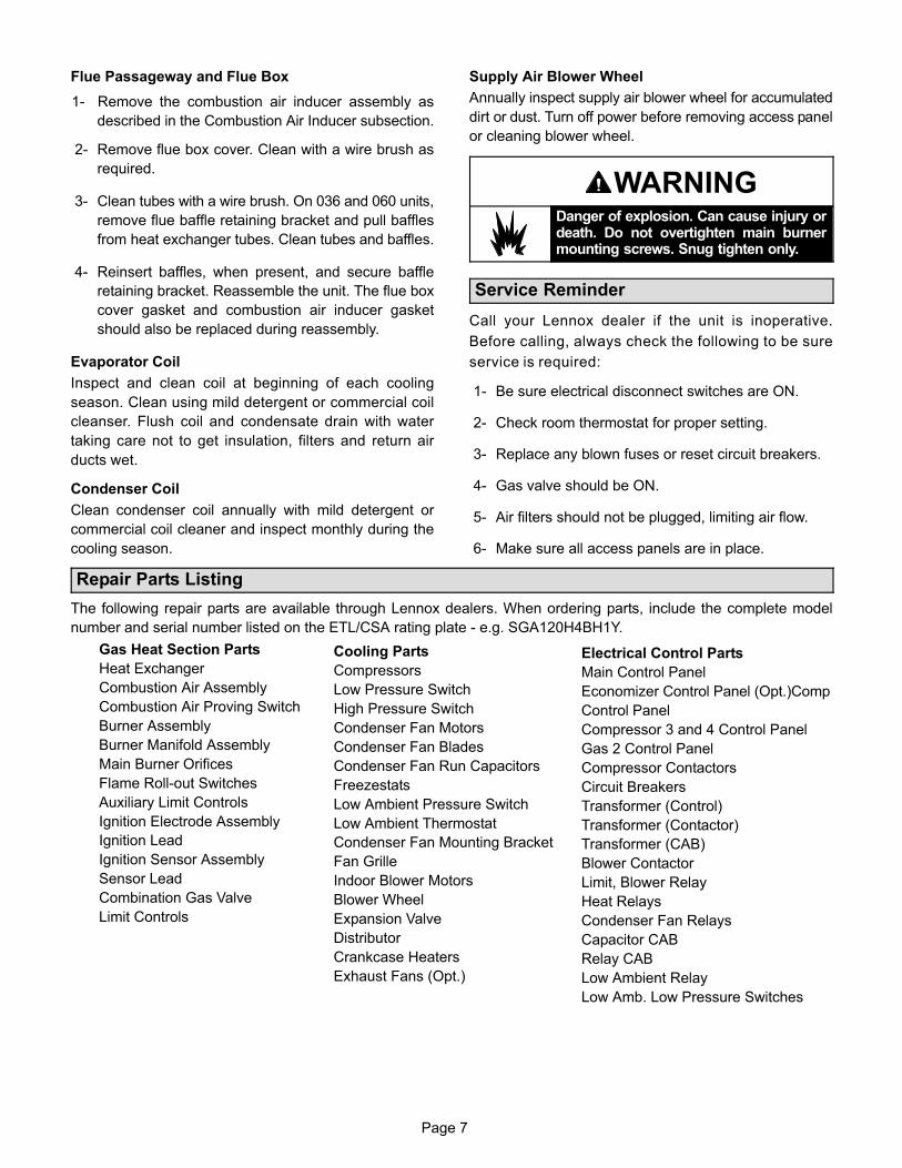
Burners
Clean burners as follows:
1− Turn off both electrical power and gas supply to unit.
2− Open or remove access panel to burner
compartment.
3− On 036 and 060 units, remove and retain four screws
securing burner support cap and lift burners from
orifices. See figure 6. On 120, 240, and 288 units,
remove and retain two screws securing burners to
burner support. See figure 7.
4− Clean as necessary and replace burners. On 036 and
060 units, replace burner support cap and secure
with retained screws. On 120, 240, and 288 units,
secure burners with retained screws. Replace burner
compartment access panel.
Page 6
HEAT SECTION − 036/060 UNITS(060 Shown)
FIGURE 6
BURNERSUPPORT CAP
HEAT SECTION − 120, 240, & 288 UNITS
FIGURE 7
BURNERSUPPORT
BURNERS
SCREWS SECURING BURNER TO BURNER
SUPPORT
5− Turn on the electrical power and the gas supply to the
unit. Follow the operating instructions attached to the
unit and use the inspection port in the access panel
to check the flame.
Electric shock hazard and danger ofexplosion. Can cause injury, death orproduct or property damage. Turn offgas and electrical power to unit beforeperforming any maintenance orservicing operations on the unit. Followlighting instructions attached to unitwhen putting unit back into operationand after service or maintenance.
WARNING!
Combustion Air Inducer
A combustion air proving switch checks combustion air
inducer operation before allowing power to the gas
controller. Gas controller will not operate if inducer is
obstructed.
Under normal operating conditions, the combustion air
blower wheel should be checked and cleaned prior to the
heating season. However, it should be examined
periodically during the heating season to establish an ideal
cleaning schedule. With power supply disconnected, the
condition of the blower wheel can be determined by
looking through the vent opening.
Cleaning Combustion Air Inducer
1− Shut off power supply and gas to unit.
2− Disconnect pressure switch air tubing from
combustion air inducer port.
3− Remove and retain four screws securing
combustion air inducer to flue box. Remove and
retain two screws from bracket supporting vent
connector. See figure 3 or 4.
4− Clean blower wheel blades with a small brush and
wipe off any dust from housing. Clean accumulated
dust from front of flue box cover.
5− Return combustion air blower motor and vent
connector to original location and secure with
retained screws. It is recommended that the
combustion air inducer gasket be replaced during
reassembly.
6− Clean combustion air inlet louvers on heat access
panel using a small brush.
Page 7
Flue Passageway and Flue Box
1− Remove the combustion air inducer assembly as
described in the Combustion Air Inducer subsection.
2− Remove flue box cover. Clean with a wire brush as
required.
3− Clean tubes with a wire brush. On 036 and 060 units,
remove flue baffle retaining bracket and pull baffles
from heat exchanger tubes. Clean tubes and baffles.
4− Reinsert baffles, when present, and secure baffle
retaining bracket. Reassemble the unit. The flue box
cover gasket and combustion air inducer gasket
should also be replaced during reassembly.
Evaporator Coil
Inspect and clean coil at beginning of each cooling
season. Clean using mild detergent or commercial coil
cleanser. Flush coil and condensate drain with water
taking care not to get insulation, filters and return air
ducts wet.
Condenser Coil
Clean condenser coil annually with mild detergent or
commercial coil cleaner and inspect monthly during the
cooling season.
Supply Air Blower Wheel
Annually inspect supply air blower wheel for accumulated
dirt or dust. Turn off power before removing access panel
or cleaning blower wheel.
WARNINGDanger of explosion. Can cause injury ordeath. Do not overtighten main burnermounting screws. Snug tighten only.
Service Reminder
Call your Lennox dealer if the unit is inoperative.
Before calling, always check the following to be sure
service is required:
1− Be sure electrical disconnect switches are ON.
2− Check room thermostat for proper setting.
3− Replace any blown fuses or reset circuit breakers.
4− Gas valve should be ON.
5− Air filters should not be plugged, limiting air flow.
6− Make sure all access panels are in place.
Repair Parts Listing
The following repair parts are available through Lennox dealers. When ordering parts, include the complete model
number and serial number listed on the ETL/CSA rating plate − e.g. SGA120H4BH1Y.
Gas Heat Section Parts
Heat Exchanger
Combustion Air Assembly
Combustion Air Proving Switch
Burner Assembly
Burner Manifold Assembly
Main Burner Orifices
Flame Roll−out Switches
Auxiliary Limit Controls
Ignition Electrode Assembly
Ignition Lead
Ignition Sensor Assembly
Sensor Lead
Combination Gas Valve
Limit Controls
Cooling Parts
Compressors
Low Pressure Switch
High Pressure Switch
Condenser Fan Motors
Condenser Fan Blades
Condenser Fan Run Capacitors
Freezestats
Low Ambient Pressure Switch
Low Ambient Thermostat
Condenser Fan Mounting Bracket
Fan Grille
Indoor Blower Motors
Blower Wheel
Expansion Valve
Distributor
Crankcase Heaters
Exhaust Fans (Opt.)
Electrical Control Parts
Main Control Panel
Economizer Control Panel (Opt.)Compr
Control Panel
Compressor 3 and 4 Control Panel
Gas 2 Control Panel
Compressor Contactors
Circuit Breakers
Transformer (Control)
Transformer (Contactor)
Transformer (CAB)
Blower Contactor
Limit, Blower Relay
Heat Relays
Condenser Fan Relays
Capacitor CAB
Relay CAB
Low Ambient Relay
Low Amb. Low Pressure Switches