Embed Size (px)
Citation preview
www.regalaustralia.com.auMO
TOR
S
SGA SERIES ENHANCED PERFORMANCE
CAST IRON
Our Heritage• Established in Wisconsin, USA in 1955. Offi cially listed on the NY Stock Exchange in 2005.
• Born in 1913, Marathon have gained over 100 years experience in design and manufacture of electric motors and generators.
Marathon has built their legacy on innovation combining magnetics and motors into a single leading technology. Their use of MagnologyTM has led to the motor industry’s fi rst axial & radial fl ux motors used in pumping applications.
• Unico has been providing innovative motion control solutions since 1967. With operations in 10 countries, Unico drives incorporate application specifi c features & functions not found in general purpose drives.
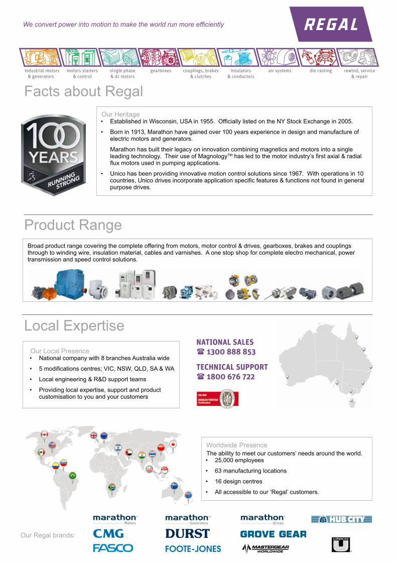
Worldwide PresenceThe ability to meet our customers’ needs around the world.• 25,000 employees
• 63 manufacturing locations
• 16 design centres
• All accessible to our ‘Regal’ customers.
Broad product range covering the complete offering from motors, motor control & drives, gearboxes, brakes and couplings through to winding wire, insulation material, cables and varnishes. A one stop shop for complete electro mechanical, power transmission and speed control solutions.
We convert power into motion to make the world run more effi ciently
Facts about Regal
Product Range
Local Expertise
colombia
Thailand
european union
singapore
new zealand
venezuelauaeunited kingdom malaysia
mexico
Our Local Presence• National company with 8 branches Australia wide
• 5 modifi cations centres; VIC, NSW, QLD, SA & WA
• Local engineering & R&D support teams
• Providing local expertise, support and product customisation to you and your customers
industrial motors motors starters single phase gearboxes couplings, brakes insulators air systems die casting rewind, service & generators & control & dc motors & clutches & conductors & repair
NATIONAL SALES 1300 888 853
TECHNICAL SUPPORT 1800 676 722
Our Regal brands:
3
SGA enhanced performance cast iron motors Sizes 71 to 355, 0.37 to 315kW PAGE
INTRODUCTION 4Standards and specifications, Efficiency & Hazardous area certification
PRODUCT CODE SPECIFICATION 4
MECHANICAL DESIGN 5Mounting arrangements Protection Materials and construction Terminal box Cooling Bearings and Lubrication Vibration, balancing and noise
ELECTRICAL DESIGN 10Voltage and frequency Temperature and altitude Rotation Duty Connection Starting Insulation Thermal protection Speed at partial loads Current at partial loads Torque characteristics
INSTALLATION, OPERATION & MAINTENANCE 16
PERFORMANCE DATA 18
DIMENSIONAL DRAWINGS 26
AIRSTREAM RATED MOTORS FOR AXIAL FANS 29Standard mount - SGAR Pad mount - SGAP
COOLING TOWER - SGAC 29
SMOKESPILL - SGAS/SGAHS 30
BRAKE MOTORS - SGAB 31
MOTORS FOR HAZARDOUS AREAS (IEC Ex & ATEX CERTIFIED) 32Motor protection types Hazardous area classifications
SLIDE RAILS 34
MODIFICATIONS, VARIATIONS AND OPTIONAL EXTRAS 35Terminal box Bearings Shafts Environmental considerations Special performance VVVF drives
TESTING SERVICES 35
TWO SPEED MOTORS 34
4
IntroductionThis catalogue details the complete range of Regal Australia SGA series motors. Standard SGA motors are three phase squirrel cage TEFC (Totally Enclosed Fan Cooled), with IEC frame sizes from 71 to 355, with CENELEC frame allocation as standard. They combine excellent electrical characteristics with the robust strength of cast iron. The standard design includes single speed 2,4,6 and 8 pole as well as a comprehensive selection of 2 speed motors. In addition to the standard design, the range includes:
SGAA - Alternative frame allocation SGAB - Brake motors SGAE - Hazardous location Ex e SGAN - Hazardous location Ex nA (formerly Ex n)SGAD - Hazardous location Ex tD (formerly DIP)SGAS - Smokespill application (formerly SGASS)SGAC - Cooling tower application (formerly SGACT)SGAR - Airstream rated for Axial flow fans SGAP - Pad mount motors
All units are supplied with F Class insulation, with temperature rise being limited to less than 80K (unless otherwise marked). This provides the end user with a wide safety margin under general operating conditions.
In addition we also offer motors wound with H Class insulation, and temperature rise still limited to 80K.
SGAH - High ambient temperature application SGAHS - H Class smokespill application
Additional protection is provided by installation of thermistors in all units from 160 frame upward to continuously protect the winding.
The conservative rating of Regal Australia type SGA motors provides additional operational safeguards, ensures long unit life, and renders this series inherently suitable for most arduous mining, industrial or agricultural applications.
Hazardous area certificationSGA motors in frames 71 to 280 are certified for use in hazardous locations as per IEC Ex and ATEX requirements, with 315 frame certificate pending (Ex nA and Ex tD only). The following certificates are currently available:IEC IECEx TSA 06.0034X Ex e, Ex nA, Ex tDATEX Sira 06ATEX9112X EX tD Sira 06ATEX4111X Ex nA, Ex nA/ Ex tD Sira 06ATEX3110X Exe, Ex e/ Ex tD
Standards and specifications The main dimensions and rated outputs of Regal Australia type SGA motors generally conform to International Standards IEC60034, IEC60072 and Australian Standard AS1359.
EfficiencyThe SGA motor range exceeds requirements of European Eff 2 and correspond to IE1 (Standard Efficiency) of the new international standard IEC 00034-30. For Eff 1 motors,
refer to Regal Australia’s HGA and PPA series catalogues.
Product code specificationWhen placing an order the motor product code should be specified. The product code of the motor is composed in accordance with the following example:
M 3 2 0 0 1 5 0 3 S G A E / 4 0 51 2 3 4 - 8 9 10 - 12 13... Suffix
Position 1 M = metric frame size
Position 2Winding design3 = Standard three phase motorsA = 2 speed fan duty single windingB = 2 speed fan duty separate windingsC = 2 speed constant torque single windingD = 2 speed constant torque separate windings
Position 3Number of poles2 = 2 poles F = 2/6 poles M = 4/12 poles4 = 4 poles G = 2/8 poles N = 6/8 poles6 = 6 poles H = 2/10 poles O = 6/10 poles8 = 8 poles I = 2/12 poles P = 6/12 polesA = 10 poles J = 4/6 poles Q = 8/10 polesC = 12 poles K = 4/8 poles R = 8/12 polesE = 2/4 poles L = 4/10 poles S = 8/16 poles
Positions 4 to 8Rated power output*(kW x 100)* Refers to high speed for 2 speed motors
Position 9Mounting arrangements1 = V1 5 = B5 8 = B3/B14B3 = B3 6 = B3/B14A 9 = B14B4 = B3/B5 7 = B14A 0 = for Pad
Mount onlyPositions 10 to 12SeriesSGA = Regal Australia SGA series
Positions 13...*Series variationBlank = Standard G = Suit NORD gearbox1 = High output design H = H Class insulationA = Alternative frame allocation L = LHS terminal boxB = Brake motor N = Ex nAC = Cooling tower P = Pad mountD = Ex tD R = Airstream ratedE = Ex e S = SmokespillF = Flying leads T = Top terminal box
* Multiple letters indicate multiple variation.
SuffixWinding design/385 = 380V / 50Hz /A05 = 1000V / 50Hz/405 = 400V / 50Hz /B05 = 1100V / 50HzBlank = 415V / 50Hz /386 = 380V / 60Hz
5
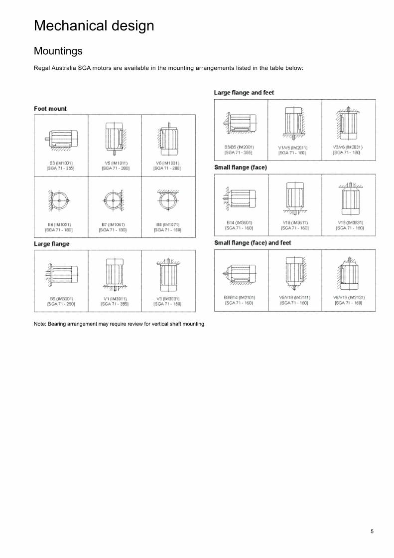
Mechanical designMountingsRegal Australia SGA motors are available in the mounting arrangements listed in the table below:
Note: Bearing arrangement may require review for vertical shaft mounting.
6
Protection
For vertically mounted motors
Motors to be mounted with the shaft vertically down must be provided with a suitable cover (available on request) to ensure foreign bodies are prevented from entering the motor.
Special care is necessary in fitting protective covers to ensure air flow is not impeded (refer to Cooling section on page 7).
To maintain IP rating, special additional measures may be required to protect the motor against the ingress of water or foreign bodies. Please contact Regal Australia for further information.
Against solar radiation
High solar radiation will result in undue temperature rise. In these circumstances motors should be screened from solar radiation by placement of adequate sunshades which do not inhibit air flow.
Degree of protection
Standard levels of enclosure protection for all SGA frame sizes for both motor and terminal box is IP55, with IP56, IP65 and IP66 available on request.
Enclosure designations comply with IEC or AS60529. The enclosure protection required will depend upon the environmental and operational conditions within which the motor is to operate.
IP standards explanation
I P 5 51-2 3 4
Positions 1 and 2 International protection rating prefix
Position 3 First characteristic numeral Degree of protection of persons against approach to live parts or contact with live or moving parts (other than smooth rotating shafts and the like) inside the enclosure, and degree of protection of equipment within the enclosure against the ingress of solid foreign bodies.
4 = Protected against solid object greater than 1.0 mm: Wires or strips of thickness greater than 1.0 mm, solid objects exceeding 1.0 mm
5 = Dust protected: Ingress of dust is not totally prevented but it does not enter in sufficient quantity to interfere with satisfactory operation of the equipment.
6 = Dust tight: No ingress of dust.
Position 4 Second characteristic numeral4 = Protected against splashing water: Water splashed
against the enclosure from any direction shall have no harmful effect.
5 = Protected against water jets: Water projected by a nozzle against the enclosure from any direction shall have no harmful effect.
6 = Protected against heavy seas: Water from heavy seas or water projected in powerful jets (larger nozzle and higher pressure than second numeral 5) shall not enter the enclosure in harmful quantities.
Materials and construction
Element
Motor frame size
71-180 200-355
Frame Cast iron Cast iron
Endshields Cast iron Cast iron
Terminal box Cast iron Cast iron
Fan Plastic (alloy available) (cast iron available)
Sheet steel blades mounted on cast iron carrier
Fan cowl Sheet steel Sheet steel
Fasteners Corrosion protected Corrosion protected
Shaft
SGA motors have standard shaft extension lengths and are provided with standard key, and drilled and tapped hole. Non standard shaft extensions are available upon special order, with shaft design outlined on a detailed drawing.
Shaft extension run out, concentricity and perpendicularity to face of standard flange mount motors, comply with normal grade tolerance as specified in IEC 60072-1 and AS1359. Precision grade tolerance is available upon special order.
Finish
Standard SGA motor color is RAL 7012 Basalt Grey. Other colors are also available. All castings and steel parts are provided with a prime coat of rust-resistant paint.
The finishing coat of enamel paint is sufficient for normal conditions, however special paint systems can be provided to accommodate stringent requirements for motors in corrosive environments. Special coatings are needed to resist such substances as acid, salt water and extreme climatic conditions.
Different colors and paint systems apply for varieties as described later in this catalogue.
7
Terminal box
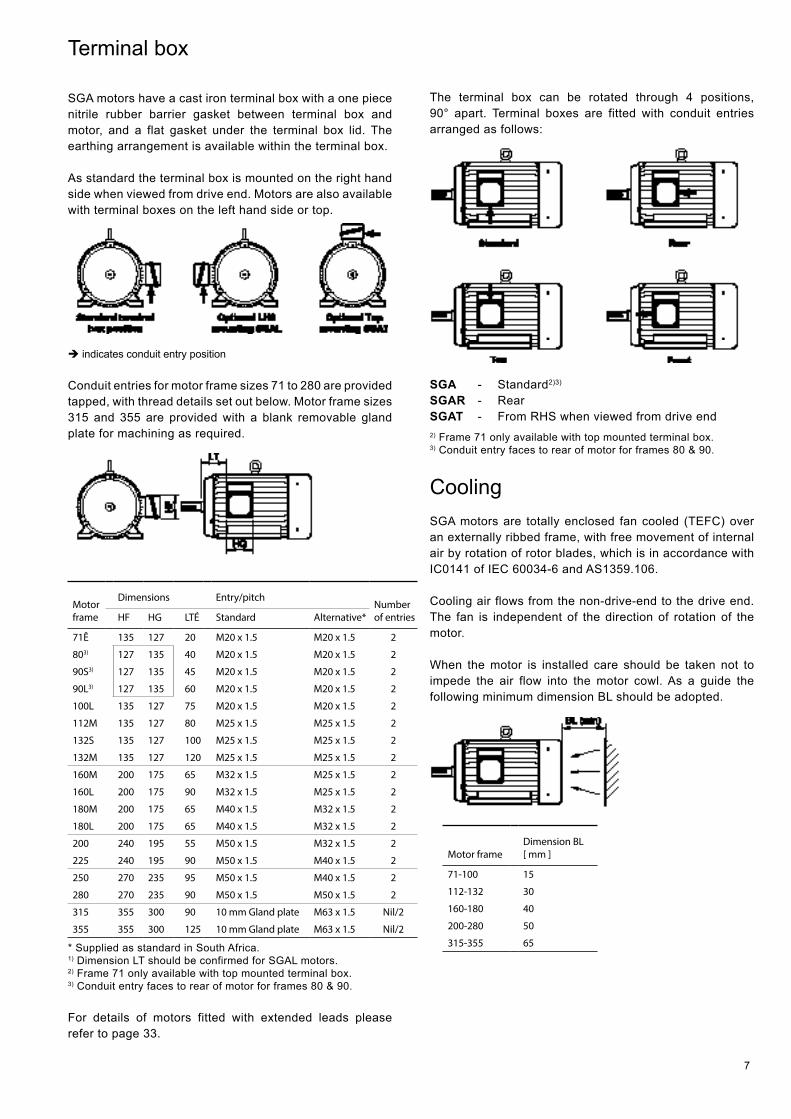
SGA motors have a cast iron terminal box with a one piece nitrile rubber barrier gasket between terminal box and motor, and a flat gasket under the terminal box lid. The earthing arrangement is available within the terminal box.
As standard the terminal box is mounted on the right hand side when viewed from drive end. Motors are also available with terminal boxes on the left hand side or top.
è indicates conduit entry position
Conduit entries for motor frame sizes 71 to 280 are provided tapped, with thread details set out below. Motor frame sizes 315 and 355 are provided with a blank removable gland plate for machining as required.
Motor frame
Dimensions Entry/pitchNumber of entriesHF HG LTÉ Standard Alternative*
71Ê 135 127 20 M20 x 1.5 M20 x 1.5 2
803) 127 135 40 M20 x 1.5 M20 x 1.5 2
90S3) 127 135 45 M20 x 1.5 M20 x 1.5 2
90L3) 127 135 60 M20 x 1.5 M20 x 1.5 2
100L 135 127 75 M20 x 1.5 M20 x 1.5 2
112M 135 127 80 M25 x 1.5 M25 x 1.5 2
132S 135 127 100 M25 x 1.5 M25 x 1.5 2
132M 135 127 120 M25 x 1.5 M25 x 1.5 2
160M 200 175 65 M32 x 1.5 M25 x 1.5 2
160L 200 175 90 M32 x 1.5 M25 x 1.5 2
180M 200 175 65 M40 x 1.5 M32 x 1.5 2
180L 200 175 65 M40 x 1.5 M32 x 1.5 2
200 240 195 55 M50 x 1.5 M32 x 1.5 2
225 240 195 90 M50 x 1.5 M40 x 1.5 2
250 270 235 95 M50 x 1.5 M40 x 1.5 2
280 270 235 90 M50 x 1.5 M50 x 1.5 2
315 355 300 90 10 mm Gland plate M63 x 1.5 Nil/2
355 355 300 125 10 mm Gland plate M63 x 1.5 Nil/2
* Supplied as standard in South Africa.1) Dimension LT should be confirmed for SGAL motors. 2) Frame 71 only available with top mounted terminal box.3) Conduit entry faces to rear of motor for frames 80 & 90.
For details of motors fitted with extended leads please refer to page 33.
The terminal box can be rotated through 4 positions, 90° apart. Terminal boxes are fitted with conduit entries arranged as follows:
SGA - Standard2)3)
SGAR - RearSGAT - From RHS when viewed from drive end2) Frame 71 only available with top mounted terminal box.3) Conduit entry faces to rear of motor for frames 80 & 90.
Cooling SGA motors are totally enclosed fan cooled (TEFC) over an externally ribbed frame, with free movement of internal air by rotation of rotor blades, which is in accordance with IC0141 of IEC 60034-6 and AS1359.106.
Cooling air flows from the non-drive-end to the drive end. The fan is independent of the direction of rotation of the motor.
When the motor is installed care should be taken not to impede the air flow into the motor cowl. As a guide the following minimum dimension BL should be adopted.
Motor frameDimension BL [ mm ]
71-100 15
112-132 30
160-180 40
200-280 50
315-355 65
8
Bearings
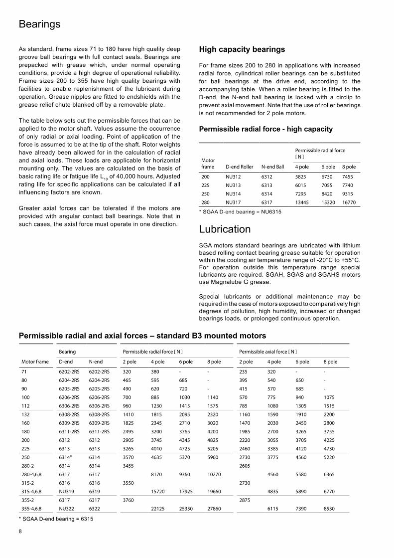
As standard, frame sizes 71 to 180 have high quality deep groove ball bearings with full contact seals. Bearings are prepacked with grease which, under normal operating conditions, provide a high degree of operational reliability. Frame sizes 200 to 355 have high quality bearings with facilities to enable replenishment of the lubricant during operation. Grease nipples are fitted to endshields with the grease relief chute blanked off by a removable plate.
The table below sets out the permissible forces that can be applied to the motor shaft. Values assume the occurrence of only radial or axial loading. Point of application of the force is assumed to be at the tip of the shaft. Rotor weights have already been allowed for in the calculation of radial and axial loads. These loads are applicable for horizontal mounting only. The values are calculated on the basis of basic rating life or fatigue life L10 of 40,000 hours. Adjusted rating life for specific applications can be calculated if all influencing factors are known.
Greater axial forces can be tolerated if the motors are provided with angular contact ball bearings. Note that in such cases, the axial force must operate in one direction.
High capacity bearings
For frame sizes 200 to 280 in applications with increased radial force, cylindrical roller bearings can be substituted for ball bearings at the drive end, according to the accompanying table. When a roller bearing is fitted to the D-end, the N-end ball bearing is locked with a circlip to prevent axial movement. Note that the use of roller bearings is not recommended for 2 pole motors.
Permissible radial force - high capacity
Motor frame D-end Roller N-end Ball
Permissible radial force [ N ]
4 pole 6 pole 8 pole
200 NU312 6312 5825 6730 7455
225 NU313 6313 6015 7055 7740
250 NU314 6314 7295 8420 9315
280 NU317 6317 13445 15320 16770
Lubrication SGA motors standard bearings are lubricated with lithium based rolling contact bearing grease suitable for operation within the cooling air temperature range of -20°C to +55°C. For operation outside this temperature range special lubricants are required. SGAH, SGAS and SGAHS motors use Magnalube G grease.
Special lubricants or additional maintenance may be required in the case of motors exposed to comparatively high degrees of pollution, high humidity, increased or changed bearings loads, or prolonged continuous operation.
Permissible radial and axial forces – standard B3 mounted motors
Motor frame
Bearing Permissible radial force [ N ] Permissible axial force [ N ]
D-end N-end 2 pole 4 pole 6 pole 8 pole 2 pole 4 pole 6 pole 8 pole
71 6202-2RS 6202-2RS 320 380 - - 235 320 - -
80 6204-2RS 6204-2RS 465 595 685 - 395 540 650 -
90 6205-2RS 6205-2RS 490 620 720 - 415 570 685 -
100 6206-2RS 6206-2RS 700 885 1030 1140 570 775 940 1075
112 6306-2RS 6306-2RS 960 1230 1415 1575 785 1080 1305 1515
132 6308-2RS 6308-2RS 1410 1815 2095 2320 1160 1590 1910 2200
160 6309-2RS 6309-2RS 1825 2345 2710 3020 1470 2030 2450 2800
180 6311-2RS 6311-2RS 2495 3200 3765 4200 1985 2700 3265 3755
200 6312 6312 2905 3745 4345 4825 2220 3055 3705 4225
225 6313 6313 3265 4010 4725 5205 2460 3385 4120 4730
250 6314* 6314 3570 4635 5370 5960 2730 3775 4560 5220
280-2 6314 6314 3455 2605
280-4,6,8 6317 6317 8170 9360 10270 4560 5580 6365
315-2 6316 6316 3550 2730
315-4,6,8 NU319 6319 15720 17925 19660 4835 5890 6770
355-2 6317 6317 3760 2875
355-4,6,8 NU322 6322 22125 25350 27860 6115 7390 8530
* SGAA D-end bearing = 6315
* SGAA D-end bearing = NU6315
9
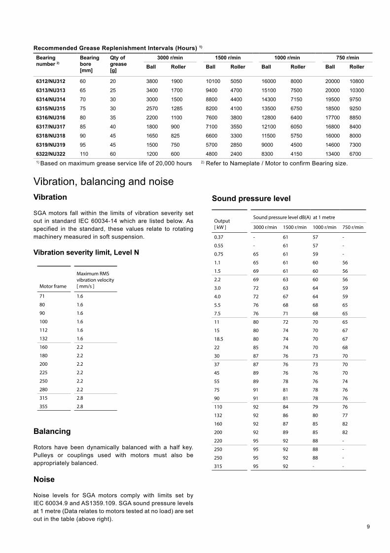
Vibration, balancing and noise Vibration
SGA motors fall within the limits of vibration severity set out in standard IEC 60034-14 which are listed below. As specified in the standard, these values relate to rotating machinery measured in soft suspension.
Vibration severity limit, Level N
Motor frame
Maximum RMS vibration velocity [ mm/s ]
71 1.6
80 1.6
90 1.6
100 1.6
112 1.6
132 1.6
160 2.2
180 2.2
200 2.2
225 2.2
250 2.2
280 2.2
315 2.8
355 2.8
Balancing
Rotors have been dynamically balanced with a half key. Pulleys or couplings used with motors must also be appropriately balanced.
Noise
Noise levels for SGA motors comply with limits set by IEC 60034.9 and AS1359.109. SGA sound pressure levels at 1 metre (Data relates to motors tested at no load) are set out in the table (above right).
Sound pressure level
Output [ kW ]
Sound pressure level dB(A) at 1 metre
3000 r/min 1500 r/min 1000 r/min 750 r/min
0.37 - 61 57 -
0.55 - 61 57 -
0.75 65 61 59 -
1.1 65 61 60 56
1.5 69 61 60 56
2.2 69 63 60 56
3.0 72 63 64 59
4.0 72 67 64 59
5.5 76 68 68 65
7.5 76 71 68 65
11 80 72 70 65
15 80 74 70 67
18.5 80 74 70 67
22 85 74 70 68
30 87 76 73 70
37 87 76 73 70
45 89 76 76 70
55 89 78 76 74
75 91 81 78 76
90 91 81 78 76
110 92 84 79 76
132 92 86 80 77
160 92 87 85 82
200 92 89 85 82
220 95 92 88 -
250 95 92 88 -
250 95 92 88 -
315 95 92 - -
Recommended Grease Replenishment Intervals (Hours) 1)
Bearing number 2)
Bearing bore [mm]
Qty of grease [g]
3000 r/min 1500 r/min 1000 r/min 750 r/minBall Roller Ball Roller Ball Roller Ball Roller
6312/NU312 60 20 3800 1900 10100 5050 16000 8000 20000 10800
6313/NU313 65 25 3400 1700 9400 4700 15100 7500 20000 10300
6314/NU314 70 30 3000 1500 8800 4400 14300 7150 19500 9750
6315/NU315 75 30 2570 1285 8200 4100 13500 6750 18500 9250
6316/NU316 80 35 2200 1100 7600 3800 12800 6400 17700 8850
6317/NU317 85 40 1800 900 7100 3550 12100 6050 16800 8400
6318/NU318 90 45 1650 825 6600 3300 11500 5750 16000 8000
6319/NU319 95 45 1500 750 5700 2850 9000 4500 14600 7300
6322/NU322 110 60 1200 600 4800 2400 8300 4150 13400 67001) Based on maximum grease service life of 20,000 hours 2) Refer to Nameplate / Motor to confirm Bearing size.
10
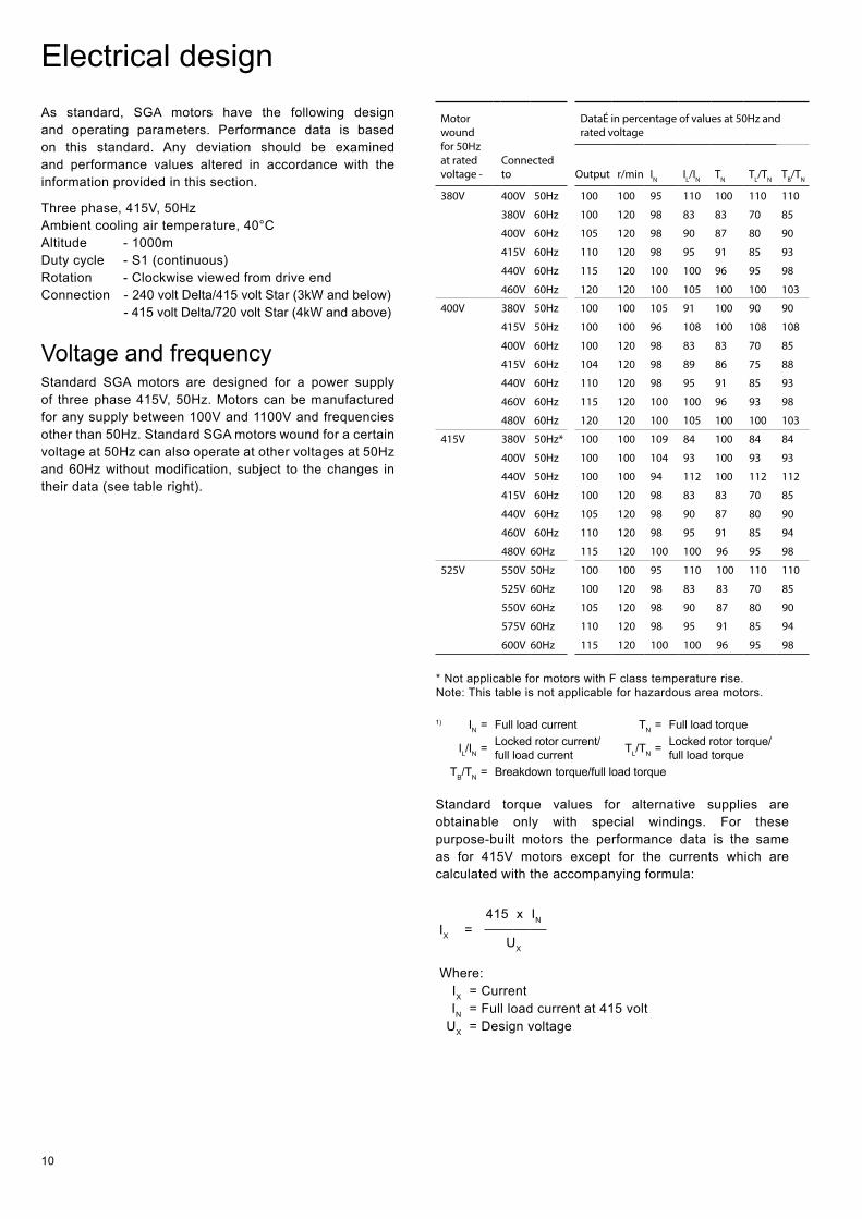
Electrical design As standard, SGA motors have the following design and operating parameters. Performance data is based on this standard. Any deviation should be examined and performance values altered in accordance with the information provided in this section.
Three phase, 415V, 50Hz Ambient cooling air temperature, 40°C Altitude - 1000m Duty cycle - S1 (continuous) Rotation - Clockwise viewed from drive end Connection - 240 volt Delta/415 volt Star (3kW and below)
- 415 volt Delta/720 volt Star (4kW and above)
Voltage and frequency Standard SGA motors are designed for a power supply of three phase 415V, 50Hz. Motors can be manufactured for any supply between 100V and 1100V and frequencies other than 50Hz. Standard SGA motors wound for a certain voltage at 50Hz can also operate at other voltages at 50Hz and 60Hz without modification, subject to the changes in their data (see table right).
Motor wound for 50Hz at rated voltage -
Connected to
DataÉ in percentage of values at 50Hz and rated voltage
Output r/min IN IL/IN TN TL/TN TB/TN
380V 400V 50Hz 100 100 95 110 100 110 110
380V 60Hz 100 120 98 83 83 70 85
400V 60Hz 105 120 98 90 87 80 90
415V 60Hz 110 120 98 95 91 85 93
440V 60Hz 115 120 100 100 96 95 98
460V 60Hz 120 120 100 105 100 100 103
400V 380V 50Hz 100 100 105 91 100 90 90
415V 50Hz 100 100 96 108 100 108 108
400V 60Hz 100 120 98 83 83 70 85
415V 60Hz 104 120 98 89 86 75 88
440V 60Hz 110 120 98 95 91 85 93
460V 60Hz 115 120 100 100 96 93 98
480V 60Hz 120 120 100 105 100 100 103
415V 380V 50Hz* 100 100 109 84 100 84 84
400V 50Hz 100 100 104 93 100 93 93
440V 50Hz 100 100 94 112 100 112 112
415V 60Hz 100 120 98 83 83 70 85
440V 60Hz 105 120 98 90 87 80 90
460V 60Hz 110 120 98 95 91 85 94
480V 60Hz 115 120 100 100 96 95 98
525V 550V 50Hz 100 100 95 110 100 110 110
525V 60Hz 100 120 98 83 83 70 85
550V 60Hz 105 120 98 90 87 80 90
575V 60Hz 110 120 98 95 91 85 94
600V 60Hz 115 120 100 100 96 95 98
* Not applicable for motors with F class temperature rise.Note: This table is not applicable for hazardous area motors.
1) IN = Full load current TN = Full load torque
IL/IN = Locked rotor current/ full load current TL/TN = Locked rotor torque/
full load torqueTB/TN = Breakdown torque/full load torque
Standard torque values for alternative supplies are obtainable only with special windings. For these purpose-built motors the performance data is the same as for 415V motors except for the currents which are calculated with the accompanying formula:
IX =415 x IN
UX
Where: IX = Current IN = Full load current at 415 volt
UX = Design voltage
11
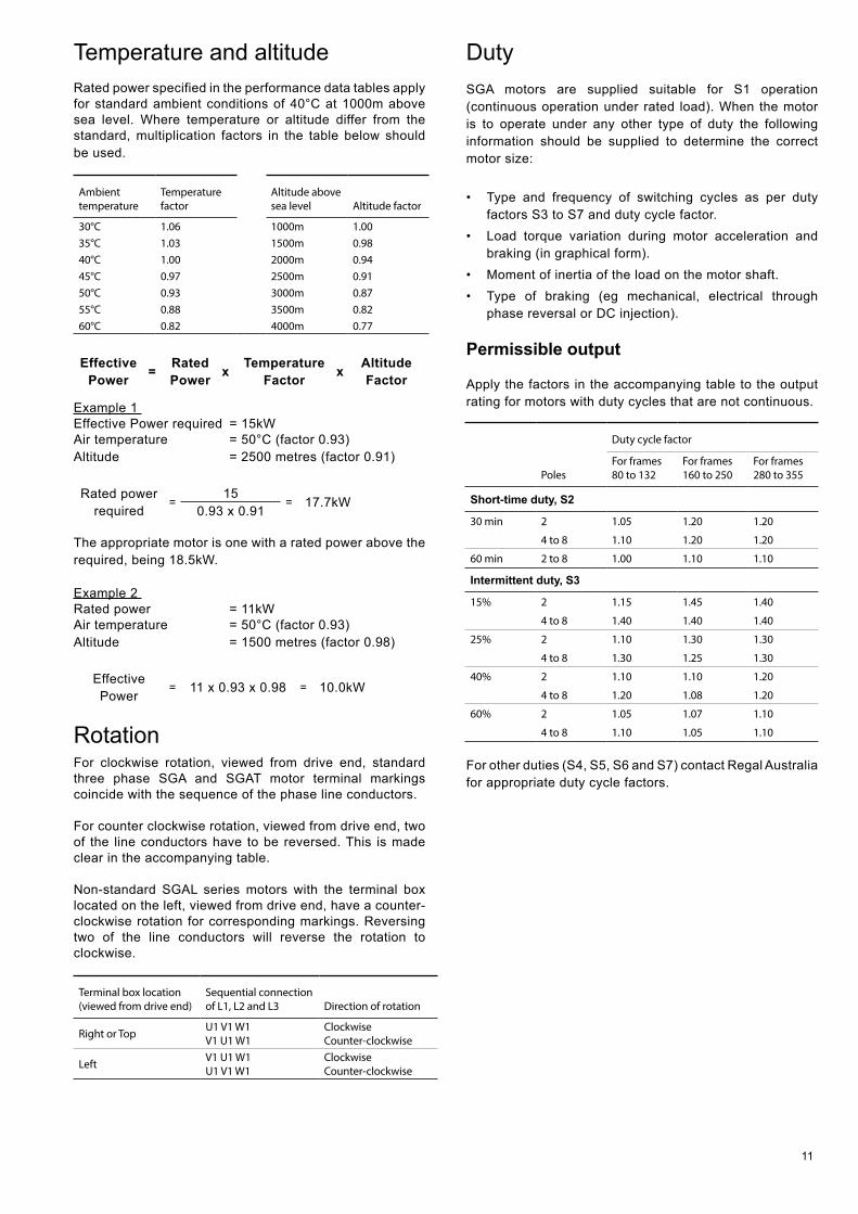
Temperature and altitude Rated power specified in the performance data tables apply for standard ambient conditions of 40°C at 1000m above sea level. Where temperature or altitude differ from the standard, multiplication factors in the table below should be used.
Ambient temperature
Temperature factor
Altitude above sea level Altitude factor
30°C 1.06 1000m 1.0035°C 1.03 1500m 0.9840°C 1.00 2000m 0.9445°C 0.97 2500m 0.9150°C 0.93 3000m 0.8755°C 0.88 3500m 0.8260°C 0.82 4000m 0.77
Effective Power = Rated
Power x Temperature Factor x Altitude
Factor
Example 1 Effective Power required = 15kWAir temperature = 50°C (factor 0.93)Altitude = 2500 metres (factor 0.91)
Rated power required
=15
= 17.7kW0.93 x 0.91
The appropriate motor is one with a rated power above the required, being 18.5kW.
Example 2 Rated power = 11kW Air temperature = 50°C (factor 0.93) Altitude = 1500 metres (factor 0.98)
Effective Power
= 11 x 0.93 x 0.98 = 10.0kW
Rotation For clockwise rotation, viewed from drive end, standard three phase SGA and SGAT motor terminal markings coincide with the sequence of the phase line conductors.
For counter clockwise rotation, viewed from drive end, two of the line conductors have to be reversed. This is made clear in the accompanying table.
Non-standard SGAL series motors with the terminal box located on the left, viewed from drive end, have a counter-clockwise rotation for corresponding markings. Reversing two of the line conductors will reverse the rotation to clockwise.
Terminal box location (viewed from drive end)
Sequential connection of L1, L2 and L3 Direction of rotation
Right or Top U1 V1 W1 V1 U1 W1
Clockwise Counter-clockwise
Left V1 U1 W1 U1 V1 W1
Clockwise Counter-clockwise
Duty SGA motors are supplied suitable for S1 operation (continuous operation under rated load). When the motor is to operate under any other type of duty the following information should be supplied to determine the correct motor size:
• Type and frequency of switching cycles as per duty factors S3 to S7 and duty cycle factor.
• Load torque variation during motor acceleration and braking (in graphical form).
• Moment of inertia of the load on the motor shaft. • Type of braking (eg mechanical, electrical through
phase reversal or DC injection).
Permissible output
Apply the factors in the accompanying table to the output rating for motors with duty cycles that are not continuous.
Poles
Duty cycle factor
For frames 80 to 132
For frames 160 to 250
For frames 280 to 355
Short-time duty, S2
30 min 2 1.05 1.20 1.20
4 to 8 1.10 1.20 1.20
60 min 2 to 8 1.00 1.10 1.10
Intermittent duty, S3
15% 2 1.15 1.45 1.40
4 to 8 1.40 1.40 1.40
25% 2 1.10 1.30 1.30
4 to 8 1.30 1.25 1.30
40% 2 1.10 1.10 1.20
4 to 8 1.20 1.08 1.20
60% 2 1.05 1.07 1.10
4 to 8 1.10 1.05 1.10
For other duties (S4, S5, S6 and S7) contact Regal Australia for appropriate duty cycle factors.
12
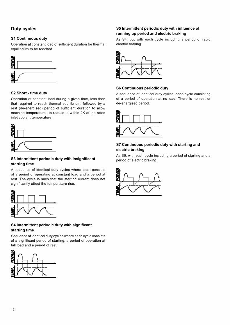
Duty cycles
S1 Continuous duty Operation at constant load of sufficient duration for thermal equilibrium to be reached.
S2 Short - time duty Operation at constant load during a given time, less than that required to reach thermal equilibrium, followed by a rest (de-energised) period of sufficient duration to allow machine temperatures to reduce to within 2K of the rated inlet coolant temperature.
S3 Intermittent periodic duty with insignificant starting time A sequence of identical duty cycles where each consists of a period of operating at constant load and a period at rest. The cycle is such that the starting current does not significantly affect the temperature rise.
S4 Intermittent periodic duty with significant starting time Sequence of identical duty cycles where each cycle consists of a significant period of starting, a period of operation at full load and a period of rest.
S5 Intermittent periodic duty with influence of running up period and electric braking As S4, but with each cycle including a period of rapid electric braking.
S6 Continuous periodic duty A sequence of identical duty cycles, each cycle consisting of a period of operation at no-load. There is no rest or de-energised period.
S7 Continuous periodic duty with starting and electric braking As S6, with each cycle including a period of starting and a period of electric braking.
13
Connection
A motor’s rated voltage must agree with the power supply line-to-line voltage. Care must therefore be taken to ensure the correct connection to the motor terminals.
Internal connections, voltages and VF drive selection
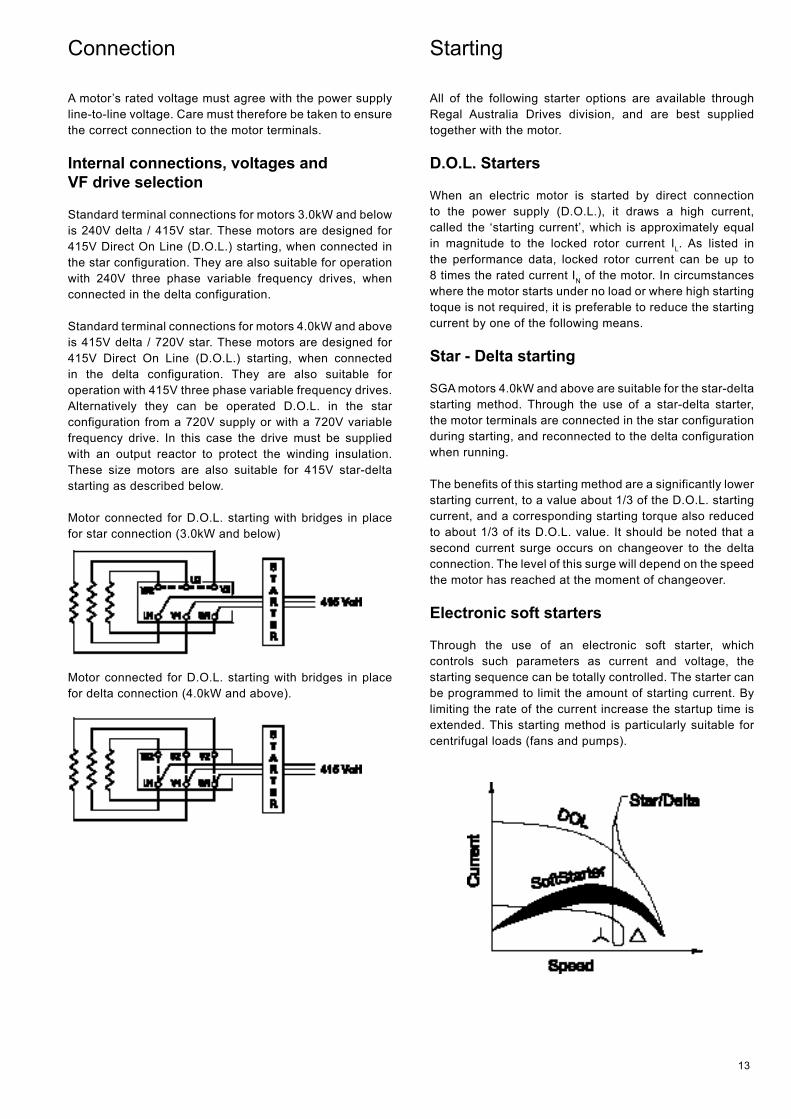
Standard terminal connections for motors 3.0kW and below is 240V delta / 415V star. These motors are designed for 415V Direct On Line (D.O.L.) starting, when connected in the star configuration. They are also suitable for operation with 240V three phase variable frequency drives, when connected in the delta configuration.
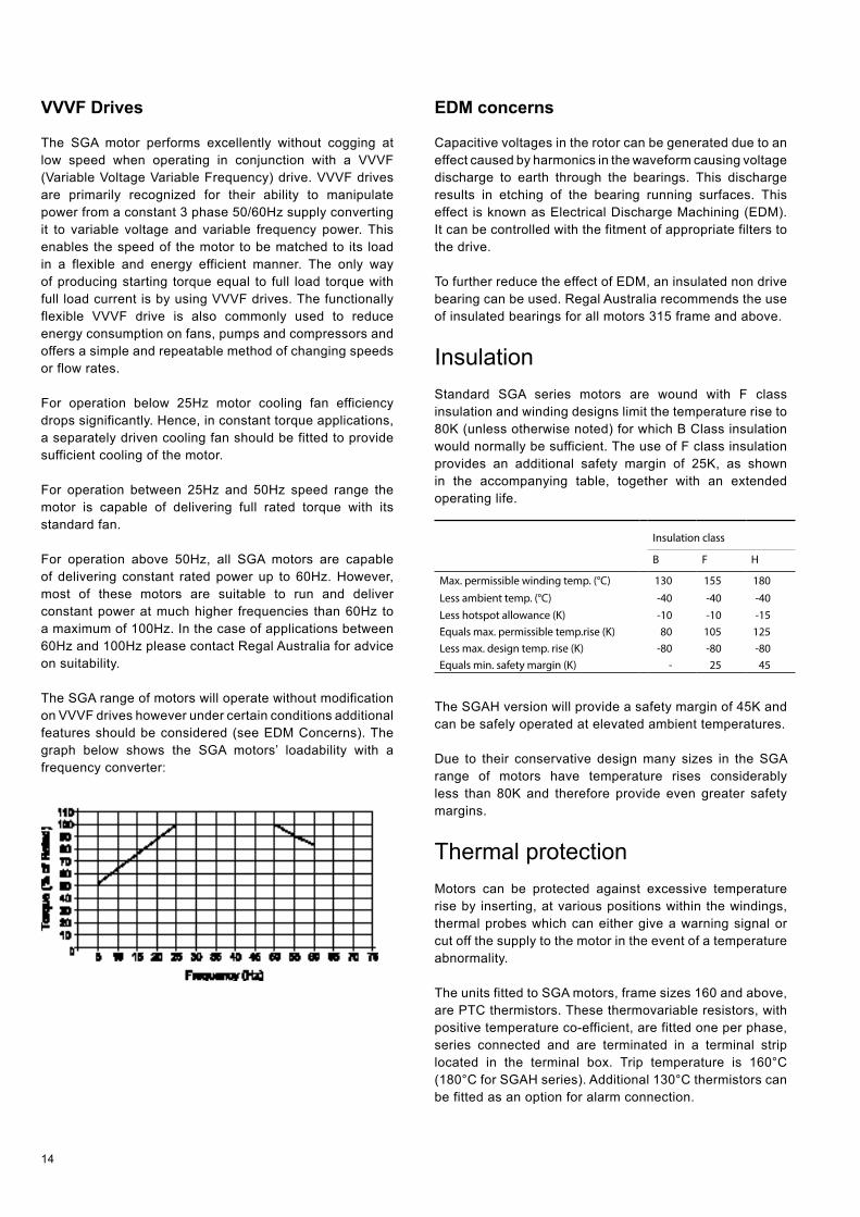
Standard terminal connections for motors 4.0kW and above is 415V delta / 720V star. These motors are designed for 415V Direct On Line (D.O.L.) starting, when connected in the delta configuration. They are also suitable for operation with 415V three phase variable frequency drives. Alternatively they can be operated D.O.L. in the star configuration from a 720V supply or with a 720V variable frequency drive. In this case the drive must be supplied with an output reactor to protect the winding insulation. These size motors are also suitable for 415V star-delta starting as described below. Motor connected for D.O.L. starting with bridges in place for star connection (3.0kW and below)
Motor connected for D.O.L. starting with bridges in place for delta connection (4.0kW and above).
Starting
All of the following starter options are available through Regal Australia Drives division, and are best supplied together with the motor.
D.O.L. Starters
When an electric motor is started by direct connection to the power supply (D.O.L.), it draws a high current, called the ‘starting current’, which is approximately equal in magnitude to the locked rotor current IL. As listed in the performance data, locked rotor current can be up to 8 times the rated current IN of the motor. In circumstances where the motor starts under no load or where high starting toque is not required, it is preferable to reduce the starting current by one of the following means.
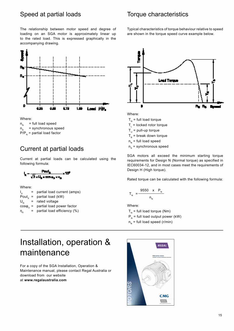
Star - Delta starting
SGA motors 4.0kW and above are suitable for the star-delta starting method. Through the use of a star-delta starter, the motor terminals are connected in the star configuration during starting, and reconnected to the delta configuration when running.
The benefits of this starting method are a significantly lower starting current, to a value about 1/3 of the D.O.L. starting current, and a corresponding starting torque also reduced to about 1/3 of its D.O.L. value. It should be noted that a second current surge occurs on changeover to the delta connection. The level of this surge will depend on the speed the motor has reached at the moment of changeover.
Electronic soft starters
Through the use of an electronic soft starter, which controls such parameters as current and voltage, the starting sequence can be totally controlled. The starter can be programmed to limit the amount of starting current. By limiting the rate of the current increase the startup time is extended. This starting method is particularly suitable for centrifugal loads (fans and pumps).
14
VVVF Drives
The SGA motor performs excellently without cogging at low speed when operating in conjunction with a VVVF (Variable Voltage Variable Frequency) drive. VVVF drives are primarily recognized for their ability to manipulate power from a constant 3 phase 50/60Hz supply converting it to variable voltage and variable frequency power. This enables the speed of the motor to be matched to its load in a flexible and energy efficient manner. The only way of producing starting torque equal to full load torque with full load current is by using VVVF drives. The functionally flexible VVVF drive is also commonly used to reduce energy consumption on fans, pumps and compressors and offers a simple and repeatable method of changing speeds or flow rates.
For operation below 25Hz motor cooling fan efficiency drops significantly. Hence, in constant torque applications, a separately driven cooling fan should be fitted to provide sufficient cooling of the motor.
For operation between 25Hz and 50Hz speed range the motor is capable of delivering full rated torque with its standard fan.
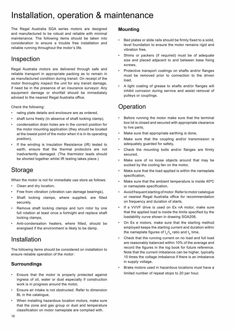
For operation above 50Hz, all SGA motors are capable of delivering constant rated power up to 60Hz. However, most of these motors are suitable to run and deliver constant power at much higher frequencies than 60Hz to a maximum of 100Hz. In the case of applications between 60Hz and 100Hz please contact Regal Australia for advice on suitability.
The SGA range of motors will operate without modification on VVVF drives however under certain conditions additional features should be considered (see EDM Concerns). The graph below shows the SGA motors’ loadability with a frequency converter:
EDM concerns
Capacitive voltages in the rotor can be generated due to an effect caused by harmonics in the waveform causing voltage discharge to earth through the bearings. This discharge results in etching of the bearing running surfaces. This effect is known as Electrical Discharge Machining (EDM). It can be controlled with the fitment of appropriate filters to the drive.
To further reduce the effect of EDM, an insulated non drive bearing can be used. Regal Australia recommends the use of insulated bearings for all motors 315 frame and above.
Insulation Standard SGA series motors are wound with F class insulation and winding designs limit the temperature rise to 80K (unless otherwise noted) for which B Class insulation would normally be sufficient. The use of F class insulation provides an additional safety margin of 25K, as shown in the accompanying table, together with an extended operating life.
Insulation class
B F H
Max. permissible winding temp. (°C) 130 155 180
Less ambient temp. (°C) -40 -40 -40Less hotspot allowance (K) -10 -10 -15Equals max. permissible temp.rise (K) 80 105 125Less max. design temp. rise (K) -80 -80 -80Equals min. safety margin (K) - 25 45
The SGAH version will provide a safety margin of 45K and can be safely operated at elevated ambient temperatures.
Due to their conservative design many sizes in the SGA range of motors have temperature rises considerably less than 80K and therefore provide even greater safety margins.
Thermal protection Motors can be protected against excessive temperature rise by inserting, at various positions within the windings, thermal probes which can either give a warning signal or cut off the supply to the motor in the event of a temperature abnormality.
The units fitted to SGA motors, frame sizes 160 and above, are PTC thermistors. These thermovariable resistors, with positive temperature co-efficient, are fitted one per phase, series connected and are terminated in a terminal strip located in the terminal box. Trip temperature is 160°C (180°C for SGAH series). Additional 130°C thermistors can be fitted as an option for alarm connection.
15
Speed at partial loads
The relationship between motor speed and degree of loading on an SGA motor is approximately linear up to the rated load. This is expressed graphically in the accompanying drawing.
Where:nN = full load speed nS = synchronous speed P/PN = partial load factor
Current at partial loadsCurrent at partial loads can be calculated using the following formula:
Where: IX = partial load current (amps)PoutX = partial load (kW)UN = rated voltagecosφX = partial load power factorηX = partial load efficiency (%)
Torque characteristics
Typical characteristics of torque behaviour relative to speed are shown in the torque speed curve example below.
Where: TN = full load torque TL = locked rotor torque TU = pull-up torque TB = break down torque nN = full load speednS = synchronous speed
SGA motors all exceed the minimum starting torque requirements for Design N (Normal torque) as specified in IEC60034-12, and in most cases meet the requirements of Design H (High torque).
Rated torque can be calculated with the following formula:
TN =9550 x PN
nN
Where: TN = full load torque (Nm) PN = full load output power (kW) nN = full load speed (r/min)
Installation, operation & maintenanceFor a copy of the SGA Installation, Operation & Maintenance manual, please contact Regal Australia or download from our website at www.regalaustralia.com
16
The Regal Australia SGA series motors are designed and manufactured to be robust and reliable with minimal maintenance. The following items should be taken into consideration to ensure a trouble free installation and reliable running throughout the motor’s life.
InspectionRegal Australia motors are delivered through safe and reliable transport in appropriate packing as to remain in as manufactured condition during transit. On receipt of the motor thoroughly inspect the unit for any transit damage, if need be in the presence of an insurance surveyor. Any equipment damage or shortfall should be immediately advised to the nearest Regal Australia office.
Check the following:• rating plate details and enclosure are as ordered,• shaft turns freely (in absence of shaft locking clamp),• condensation drain holes are in the correct position for
the motor mounting application (they should be located at the lowest point of the motor when it is in its operating position),
• If the winding is Insulation Resistance (IR) tested to earth, ensure that the thermal protectors are not inadvertently damaged. (The thermistor leads should be shorted together whilst IR testing takes place.)
StorageWhen the motor is not for immediate use store as follows:• Clean and dry location,• Free from vibration (vibration can damage bearings),• Shaft locking clamps, where supplied, are fitted
securely,• Remove shaft locking clamps and turn rotor by one
full rotation at least once a fortnight and replace shaft locking clamps,
• Anti-condensation heaters, where fitted, should be energised if the environment is likely to be damp.
InstallationThe following items should be considered on installation to ensure reliable operation of the motor:
Surroundings
• Ensure that the motor is properly protected against ingress of oil, water or dust especially if construction work is in progress around the motor,
• Ensure air intake is not obstructed. Refer to dimension BL in the catalogue,
• When installing hazardous location motors, make sure that the zone and gas group or dust and temperature classification on motor nameplate are complied with.
Installation, operation & maintenanceMounting
• Bed plates or slide rails should be firmly fixed to a solid, level foundation to ensure the motor remains rigid and vibration free,
• Shims or packers (if required) must be of adequate size and placed adjacent to and between base fixing screws,
• Protective transport coatings on shafts and/or flanges must be removed prior to connection to the driven load,
• A light coating of grease to shafts and/or flanges will inhibit corrosion during service and assist removal of pulleys or couplings.
Operation• Before running the motor make sure that the terminal
box lid is closed and secured with appropriate clearance to live parts,
• Make sure that appropriate earthing is done,• Make sure that the coupling and/or transmission is
adequately guarded for safety,• Check the mounting bolts and/or flanges are firmly
secured,• Make sure of no loose objects around that may be
sucked by the cooling fan on the motor,• Make sure that the load applied is within the nameplate
specification,• Make sure that the ambient temperature is inside 40ºC
or nameplate specification,• Avoid frequent starting of motor. Refer to motor catalogue
or nearest Regal Australia office for recommendation on frequency and duration of starts,
• If a VVVF drive is used on Ex nA motor, make sure that the applied load is inside the limits specified by the loadability curve shown in drawing SGA208,
• On Ex e motors, make sure that the starting method employed keeps the starting current and duration within the nameplate figures of IA/IN ratio and tE time,
• Check that the running current on no load and full load are reasonably balanced within 10% of the average and record the figures in the log book for future reference. Note that the current imbalance can be higher, typically 10 times the voltage imbalance if there is an imbalance in supply voltage,
• Brake motors used in hazardous locations must have a limited number of repeat stops to 20 per hour.
17
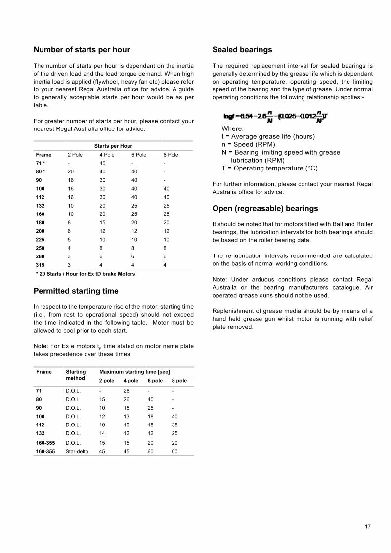
Number of starts per hour
The number of starts per hour is dependant on the inertia of the driven load and the load torque demand. When high inertia load is applied (flywheel, heavy fan etc) please refer to your nearest Regal Australia office for advice. A guide to generally acceptable starts per hour would be as per table.
For greater number of starts per hour, please contact your nearest Regal Australia office for advice.
Starts per HourFrame 2 Pole 4 Pole 6 Pole 8 Pole71 * - 40 - -80 * 20 40 40 -90 16 30 40 -100 16 30 40 40112 16 30 40 40132 10 20 25 25160 10 20 25 25180 8 15 20 20200 6 12 12 12225 5 10 10 10250 4 8 8 8280 3 6 6 6315 3 4 4 4
* 20 Starts / Hour for Ex tD brake Motors
Permitted starting time
In respect to the temperature rise of the motor, starting time (i.e., from rest to operational speed) should not exceed the time indicated in the following table. Motor must be allowed to cool prior to each start.
Note: For Ex e motors tE time stated on motor name plate takes precedence over these times
Frame Starting method
Maximum starting time [sec]2 pole 4 pole 6 pole 8 pole
71 D.O.L. - 26 - -80 D.O.L 15 26 40 -90 D.O.L. 10 15 25 -100 D.O.L. 12 13 18 40112 D.O.L. 10 10 18 35132 D.O.L. 14 12 12 25
160-355 D.O.L. 15 15 20 20160-355 Star-delta 45 45 60 60
Sealed bearings
The required replacement interval for sealed bearings is generally determined by the grease life which is dependant on operating temperature, operating speed, the limiting speed of the bearing and the type of grease. Under normal operating conditions the following relationship applies:-
Where:t = Average grease life (hours) n = Speed (RPM) N = Bearing limiting speed with grease
lubrication (RPM)T = Operating temperature (°C)
For further information, please contact your nearest Regal Australia office for advice.
Open (regreasable) bearings
It should be noted that for motors fitted with Ball and Roller bearings, the lubrication intervals for both bearings should be based on the roller bearing data.
The re-lubrication intervals recommended are calculated on the basis of normal working conditions.
Note: Under arduous conditions please contact Regal Australia or the bearing manufacturers catalogue. Air operated grease guns should not be used.
Replenishment of grease media should be by means of a hand held grease gun whilst motor is running with relief plate removed.
18
Standards for TEFC motors
Classifying Authority
Service Ambient temp °C
Permissible temp rise K
Witnessed tests for essential service
Class B Class F
Lloyds Register of Shipping (LRS)
Restricted 40 75 90 ≥ 100kW
Unrestricted 45 70 90
Det Norske Veritas (DNV)
Restricted 35* 80 100 ≥ 100kW
Unrestricted 45 70
Germanischer Lloyd (GL)
Restricted 40 80 100 ≥ 100kW
Unrestricted 45 75 95
American Bureau of Shipping (ABS)
Non-essential 40 80 105 ≥ 100kW
Essential 50 70 95
Korean Register of Shipping (KRS)
Essential and non-essential
50 70 90 All motors
Chinese Classification Societies (CCS)
Essential and non-essential
50 70 90 **
Auxiliaries 45 75 95 **
Bureau Veritas (BV)
40 80 100 ≥ 100kW
Essential 50 70 90
Registro Italiano Navale (RINA)
Non-essential 40 80 100 ≥ 100kW
Essential 50 70 90
Nippon Kaiji Kyokai (NKK)
Essential and non-essential
45 75 95 All motors
* Refrigerated holds only
** Refer to Regal Australia - discretionary upon requirements
Maintenance
Reliable, trouble free operation of a motor needs regular maintenance. Exact maintenance needs vary based on the site conditions. To obtain reliable service from the motor, the following maintenance schedule may be used as a guide. An authorised service agent must carry out maintenance of hazardous location motors SGAE, SGAN or SGAD.
A. Ensure air intake space is unobstructed.B. On a weekly basis use an air hose to ensure all
air ways are clear and free of dust.C. Once every month, check motor for
condensation. Replace drain plugs before starting if they are blocked or found missing.
D. Do not wash the motor down unless it is IP66 rated.
E. On a quarterly basis-(i) Check the motor terminals for tightness and
proper contact,(ii) If terminal lug/s are discoloured, re-terminate
with fresh lugs,(iii) Check operation of starting equipment,
ensuring all terminations are tight.(iv) Check mechanical operation of thermal
overload relays, if any,(v) Check mechanical operation of thermistor
relays, if fitted,(vi) Check operation of anti-condensation
heaters, if fitted.F. On a six monthly basis, in addition to the items in
‘E’ -(i) Check winding resistance between supply
terminals and compare to original value and enter in log book.
(ii) Check supply voltage at motor terminals and record in log book.
(iii) Check bearings for abnormal noise/overheating.
G. On an annual basis, in addition to the items in ‘E’ and ‘F’ -(i) Re-grease the bearings as recommended
in the following table. Frames 71-180 use sealed bearings. Frames 200-280 use open re-greasable bearings. When re-greasing bearings ensure that the correct type of grease is used. If in doubt about the existing grease type, clean out the old grease thoroughly from bearings and bearing housings, prior to regreasing. WARNING: NEVER MIX GREASE OF DIFFERENT TYPES Use lithium based grease such as Shell Alvania R3 or equivalent unless otherwise specified. SGAH, SGASS and SGAHS motors require extra high temperature grease such as Magnalube G or equivalent.
(ii) Completely disassemble stator, rotor apart and clean thoroughly.
(iii) Check bearings for wear/damage – replace as necessary.
(iv) Check all bolts and nuts for cracks or damage – replace as necessary.
(v) Check all holding down bolts for signs of fatigue or damage – replace as necessary.
(vi) After re-assembly, check and record in the log book- Insulation resistance by megger No load current and voltages Full load current and voltages Ensure that these figures compare well with the original records in the log book.
(vii) Check and ensure that the cooling fan is operational.
19
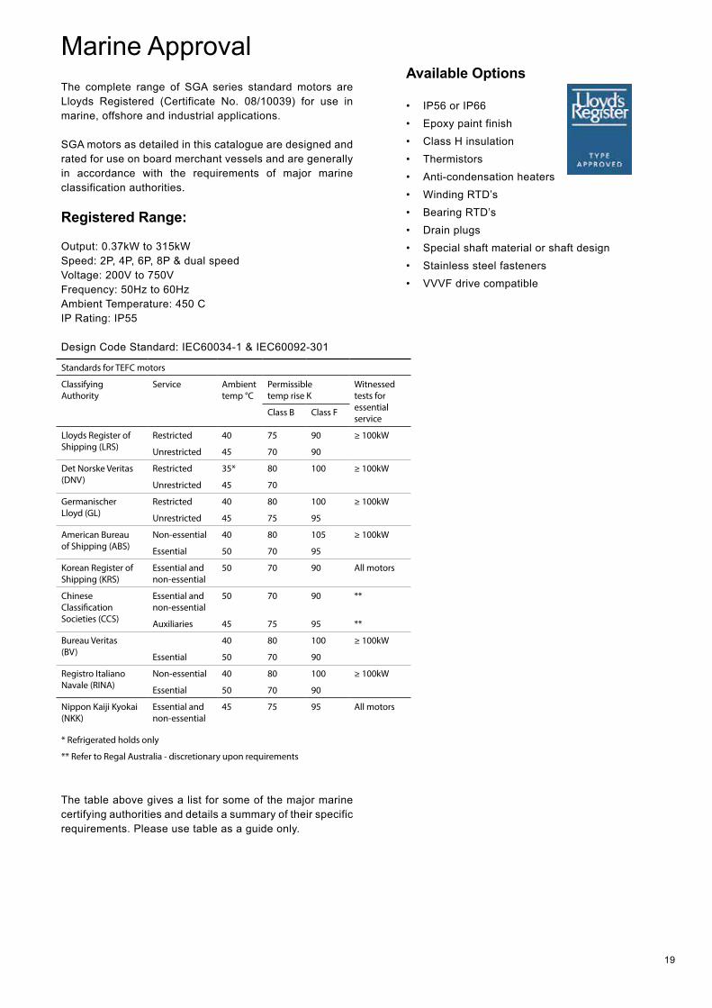
Marine ApprovalThe complete range of SGA series standard motors are Lloyds Registered (Certificate No. 08/10039) for use in marine, offshore and industrial applications.
SGA motors as detailed in this catalogue are designed and rated for use on board merchant vessels and are generally in accordance with the requirements of major marine classification authorities.
Registered Range:
Output: 0.37kW to 315kWSpeed: 2P, 4P, 6P, 8P & dual speedVoltage: 200V to 750VFrequency: 50Hz to 60HzAmbient Temperature: 450 CIP Rating: IP55
Design Code Standard: IEC60034-1 & IEC60092-301
Standards for TEFC motors
Classifying Authority
Service Ambient temp °C
Permissible temp rise K
Witnessed tests for essential service
Class B Class F
Lloyds Register of Shipping (LRS)
Restricted 40 75 90 ≥ 100kW
Unrestricted 45 70 90
Det Norske Veritas (DNV)
Restricted 35* 80 100 ≥ 100kW
Unrestricted 45 70
Germanischer Lloyd (GL)
Restricted 40 80 100 ≥ 100kW
Unrestricted 45 75 95
American Bureau of Shipping (ABS)
Non-essential 40 80 105 ≥ 100kW
Essential 50 70 95
Korean Register of Shipping (KRS)
Essential and non-essential
50 70 90 All motors
Chinese Classification Societies (CCS)
Essential and non-essential
50 70 90 **
Auxiliaries 45 75 95 **
Bureau Veritas (BV)
40 80 100 ≥ 100kW
Essential 50 70 90
Registro Italiano Navale (RINA)
Non-essential 40 80 100 ≥ 100kW
Essential 50 70 90
Nippon Kaiji Kyokai (NKK)
Essential and non-essential
45 75 95 All motors
* Refrigerated holds only
** Refer to Regal Australia - discretionary upon requirements
Available Options
• IP56 or IP66• Epoxy paint finish• Class H insulation• Thermistors• Anti-condensation heaters• Winding RTD’s• Bearing RTD’s• Drain plugs• Special shaft material or shaft design• Stainless steel fasteners• VVVF drive compatible
The table above gives a list for some of the major marine certifying authorities and details a summary of their specific requirements. Please use table as a guide only.

20
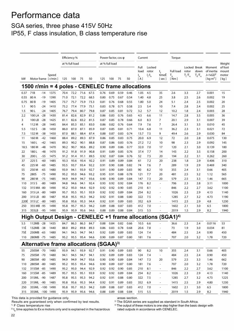
Performance data SGA series, three phase 415V 50Hz IP55, F class insulation, B class temperature rise
This data is provided for guidance only. Results are guaranteed only when confirmed by test results. 1) F Class temperature rise2) tE time applies to Ex e motors only and is explained in the hazardous
areas section.
3) The SGAA series are supplied as standard in South Africa.4) The output of these motors is one step higher than the basic design
with rated outputs in accordance with CENELEC.
kW Motor frame Speed [ r/min ]
Efficiency % Power factor, cos φ Current
tE timeÊ [ sec ]
Torque
Moment of inertia J=¼GD² [ kg m² ]
Weight of foot mount motor [ kg ]
at % full load at % full load Full load IN [ A ]
Locked rotor lL/IN
Full load TN [ Nm ]
Locked rotor TL/TN
Break down TB/TN 125 100 75 50 125 100 75 50
3000 r/min = 2 poles - CENELEC frame allocations0.75 80 A -19 2820 74.4 76.0 75.8 72.5 0.88 0.84 0.78 0.67 1.61 6.1 17 2.5 2.8 4.0 0.001 181.1 80 B -19 2835 76.7 78.5 79.2 77.2 0.89 0.86 0.82 0.72 2.3 5.9 11 3.7 2.7 3.0 0.001 191.5 90 S -24 2860 79.3 80.5 80.4 77.6 0.88 0.85 0.80 0.70 3.0 6.7 11 5.0 2.9 3.5 0.001 222.2 90 L -24 2830 79.5 81.8 82.8 81.6 0.90 0.87 0.83 0.74 4.3 6.4 6 7.4 2.8 2.8 0.001 263 100 L -28 2870 82.0 83.3 83.3 81.2 0.90 0.88 0.84 0.76 5.7 7.5 7 10.0 2.8 3.4 0.003 364 112 M -28 2900 85.3 86.1 86.1 84.2 0.90 0.89 0.84 0.75 7.4 7.9 7 13.2 2.7 3.5 0.006 455.5 132SA -38 2925 86.7 86.8 86.0 81.7 0.89 0.87 0.82 0.69 10.2 7.0 11 18.0 2.4 2.3 0.011 707.5 132 SB -38 2895 86.0 87.0 87.2 85.5 0.91 0.91 0.89 0.84 13.3 7.2 7 24.7 2.1 2.8 0.013 7711 160 MA -42 2935 88.3 88.4 87.4 85.4 0.89 0.89 0.87 0.83 19.6 7.0 25 35.8 2.2 2.9 0.038 12215 160 MB -42 2940 89.4 89.8 89.6 87.3 0.92 0.91 0.92 0.83 25.4 7.2 10 48.7 1.8 2.6 0.050 13218.5 160 L -42 2930 90.1 90.4 90.1 88.5 0.91 0.91 0.90 0.87 31.4 7.3 10 60.3 2.3 2.9 0.055 15022 180 M -48 2945 90.3 90.6 89.9 89.0 0.91 0.92 0.88 0.86 36.6 6.8 7 71.3 2.3 2.4 0.075 18230 200 LA -55 2960 92.6 92.6 92.0 90.2 0.90 0.90 0.89 0.82 49.8 4.7 7 96.8 2.4 3.3 0.124 24037 200 LB -55 2960 92.6 92.6 92.0 90.0 0.90 0.89 0.87 0.80 62 7.6 10 119 2.4 3.1 0.139 26045 225 M -55 2975 93.3 93.0 92.3 90.2 0.90 0.89 0.88 0.83 75 8.3 17 144 2.6 2.9 0.233 32555 250 M -60 2975 93.7 93.4 92.6 90.4 0.90 0.89 0.88 0.82 92 8.5 17 177 2.6 3.2 0.312 40575 280S -65 2975 94.5 94.4 93.9 92.3 0.91 0.91 0.90 0.88 122 7.5 15 241 2.7 3.0 0.597 55090 280 M -65 2980 94.7 94.7 94.2 92.1 0.91 0.92 0.91 0.88 144 7.9 12 288 2.8 3.1 0.675 610110 315S -65 2980 95.0 94.7 93.9 92.0 0.89 0.89 0.88 0.84 181 6.6 - 353 2.5 3.0 1.18 980132 315 MA -65 2980 95.5 95.3 94.6 93.0 0.90 0.91 0.89 0.87 213 7.0 - 423 2.6 2.9 1.82 1080160 315 LA -65 2980 95.7 95.5 94.9 93.6 0.88 0.90 0.89 0.86 259 6.4 - 513 2.4 2.9 2.08 1160200 315 LB -65 2980 95.8 95.5 95.0 93.4 0.91 0.87 0.86 0.80 334 6.6 - 641 2.6 2.9 2.38 1210220É 315 LC -65 2980 95.8 95.6 95.2 93.7 0.92 0.88 0.86 0.81 361 6.1 - 705 2.3 2.6 2.45 1250250É 355 MB -75 2985 94.5 94.5 94.0 92.5 0.90 0.90 0.88 0.81 407 6.8 - 800 1.7 3.1 3.00 1770315É 355 LB -75 2985 94.8 94.1 92.8 90.2 0.88 0.88 0.86 0.80 530 8.1 - 1008 2.8 3.0 3.50 1900
High Output Design - CENELEC +1 frame allocations (SGA1)4)
4 100LB -28 2875 83.1 84.5 84.5 83.2 0.89 0.87 0.83 0.74 7.6 8.1 - 13.3 3.3 3.1 0.004 395.5 112MB -28 2890 85.4 86.4 86.4 84.7 0.91 0.89 0.86 0.78 9.9 7.8 - 18.2 2.8 3.4 0.011 7011É 132M -38 2900 87.7 88.8 89.1 87.9 0.92 0.92 0.91 0.87 18.8 7.3 - 36.2 2.0 2.9 0.015 7422 160L -42 2925 91.0 91.6 91.6 90.6 0.91 0.91 0.91 0.87 36.6 7.8 - 71.8 2.3 2.7 0.066 15745 200L -55 2955 93.0 93.2 92.8 91.3 0.90 0.89 0.86 0.79 76 8.6 - 145 2.8 3.1 0.167 27575É 250MB -60 2970 93.9 93.8 93.4 92.4 0.91 0.91 0.88 0.84 123 7.0 - 241 2.1 2.3 0.426 430110É 280MB -65 2978 94.5 94.6 94.2 93.0 0.90 0.89 0.86 0.78 182 8.2 - 353 3.2 3.4 0.825 670
Alternative frame allocations (SGAA)3)
55 250SM -60 2975 93.7 93.4 92.6 90.4 0.90 0.89 0.88 0.82 92 8.5 17 177 2.6 3.2 0.312 40575 250SM -60 2970 93.9 93.8 93.4 92.4 0.91 0.91 0.88 0.84 123 7.0 - 241 2.1 2.3 0.426 43090 280SM -65 2980 94.7 94.7 94.2 92.1 0.91 0.92 0.91 0.88 144 7.9 12 288 2.8 3.1 0.675 610110 280SM -65 2978 94.5 94.6 94.2 93.0 0.90 0.89 0.86 0.78 182 8.2 - 353 3.2 3.4 0.825 670132 315SM -65 2980 95.5 95.3 94.6 93.0 0.90 0.91 0.89 0.87 213 7.0 - 423 2.6 2.9 1.82 1080160 315ML -65 2980 95.7 95.5 94.9 93.6 0.88 0.90 0.89 0.86 259 6.4 - 513 2.4 2.9 2.08 1160200 315ML -70 2980 95.8 95.5 95.0 93.4 0.91 0.87 0.86 0.80 334 6.6 - 641 2.6 2.9 2.38 1210220 315ML -70 2980 95.8 95.6 95.2 93.7 0.92 0.88 0.86 0.81 361 6.1 - 705 2.3 2.6 2.45 1250
21
kW Motor frame Speed [ r/min ]
Efficiency % Power factor, cos φ Current
tE timeÊ [ sec ]
Torque
Moment of inertia J=¼GD² [ kg m² ]
Weight of foot mount motor [ kg ]
at % full load at % full load Full load IN [ A ]
Locked rotor lL/IN
Full load TN [ Nm ]
Locked rotor TL/TN
Break down TB/TN 125 100 75 50 125 100 75 50
3000 r/min = 2 poles - CENELEC frame allocations0.75 80 A -19 2820 74.4 76.0 75.8 72.5 0.88 0.84 0.78 0.67 1.61 6.1 17 2.5 2.8 4.0 0.001 181.1 80 B -19 2835 76.7 78.5 79.2 77.2 0.89 0.86 0.82 0.72 2.3 5.9 11 3.7 2.7 3.0 0.001 191.5 90 S -24 2860 79.3 80.5 80.4 77.6 0.88 0.85 0.80 0.70 3.0 6.7 11 5.0 2.9 3.5 0.001 222.2 90 L -24 2830 79.5 81.8 82.8 81.6 0.90 0.87 0.83 0.74 4.3 6.4 6 7.4 2.8 2.8 0.001 263 100 L -28 2870 82.0 83.3 83.3 81.2 0.90 0.88 0.84 0.76 5.7 7.5 7 10.0 2.8 3.4 0.003 364 112 M -28 2900 85.3 86.1 86.1 84.2 0.90 0.89 0.84 0.75 7.4 7.9 7 13.2 2.7 3.5 0.006 455.5 132SA -38 2925 86.7 86.8 86.0 81.7 0.89 0.87 0.82 0.69 10.2 7.0 11 18.0 2.4 2.3 0.011 707.5 132 SB -38 2895 86.0 87.0 87.2 85.5 0.91 0.91 0.89 0.84 13.3 7.2 7 24.7 2.1 2.8 0.013 7711 160 MA -42 2935 88.3 88.4 87.4 85.4 0.89 0.89 0.87 0.83 19.6 7.0 25 35.8 2.2 2.9 0.038 12215 160 MB -42 2940 89.4 89.8 89.6 87.3 0.92 0.91 0.92 0.83 25.4 7.2 10 48.7 1.8 2.6 0.050 13218.5 160 L -42 2930 90.1 90.4 90.1 88.5 0.91 0.91 0.90 0.87 31.4 7.3 10 60.3 2.3 2.9 0.055 15022 180 M -48 2945 90.3 90.6 89.9 89.0 0.91 0.92 0.88 0.86 36.6 6.8 7 71.3 2.3 2.4 0.075 18230 200 LA -55 2960 92.6 92.6 92.0 90.2 0.90 0.90 0.89 0.82 49.8 4.7 7 96.8 2.4 3.3 0.124 24037 200 LB -55 2960 92.6 92.6 92.0 90.0 0.90 0.89 0.87 0.80 62 7.6 10 119 2.4 3.1 0.139 26045 225 M -55 2975 93.3 93.0 92.3 90.2 0.90 0.89 0.88 0.83 75 8.3 17 144 2.6 2.9 0.233 32555 250 M -60 2975 93.7 93.4 92.6 90.4 0.90 0.89 0.88 0.82 92 8.5 17 177 2.6 3.2 0.312 40575 280S -65 2975 94.5 94.4 93.9 92.3 0.91 0.91 0.90 0.88 122 7.5 15 241 2.7 3.0 0.597 55090 280 M -65 2980 94.7 94.7 94.2 92.1 0.91 0.92 0.91 0.88 144 7.9 12 288 2.8 3.1 0.675 610110 315S -65 2980 95.0 94.7 93.9 92.0 0.89 0.89 0.88 0.84 181 6.6 - 353 2.5 3.0 1.18 980132 315 MA -65 2980 95.5 95.3 94.6 93.0 0.90 0.91 0.89 0.87 213 7.0 - 423 2.6 2.9 1.82 1080160 315 LA -65 2980 95.7 95.5 94.9 93.6 0.88 0.90 0.89 0.86 259 6.4 - 513 2.4 2.9 2.08 1160200 315 LB -65 2980 95.8 95.5 95.0 93.4 0.91 0.87 0.86 0.80 334 6.6 - 641 2.6 2.9 2.38 1210220É 315 LC -65 2980 95.8 95.6 95.2 93.7 0.92 0.88 0.86 0.81 361 6.1 - 705 2.3 2.6 2.45 1250250É 355 MB -75 2985 94.5 94.5 94.0 92.5 0.90 0.90 0.88 0.81 407 6.8 - 800 1.7 3.1 3.00 1770315É 355 LB -75 2985 94.8 94.1 92.8 90.2 0.88 0.88 0.86 0.80 530 8.1 - 1008 2.8 3.0 3.50 1900
High Output Design - CENELEC +1 frame allocations (SGA1)4)
4 100LB -28 2875 83.1 84.5 84.5 83.2 0.89 0.87 0.83 0.74 7.6 8.1 - 13.3 3.3 3.1 0.004 395.5 112MB -28 2890 85.4 86.4 86.4 84.7 0.91 0.89 0.86 0.78 9.9 7.8 - 18.2 2.8 3.4 0.011 7011É 132M -38 2900 87.7 88.8 89.1 87.9 0.92 0.92 0.91 0.87 18.8 7.3 - 36.2 2.0 2.9 0.015 7422 160L -42 2925 91.0 91.6 91.6 90.6 0.91 0.91 0.91 0.87 36.6 7.8 - 71.8 2.3 2.7 0.066 15745 200L -55 2955 93.0 93.2 92.8 91.3 0.90 0.89 0.86 0.79 76 8.6 - 145 2.8 3.1 0.167 27575É 250MB -60 2970 93.9 93.8 93.4 92.4 0.91 0.91 0.88 0.84 123 7.0 - 241 2.1 2.3 0.426 430110É 280MB -65 2978 94.5 94.6 94.2 93.0 0.90 0.89 0.86 0.78 182 8.2 - 353 3.2 3.4 0.825 670
Alternative frame allocations (SGAA)3)
55 250SM -60 2975 93.7 93.4 92.6 90.4 0.90 0.89 0.88 0.82 92 8.5 17 177 2.6 3.2 0.312 40575 250SM -60 2970 93.9 93.8 93.4 92.4 0.91 0.91 0.88 0.84 123 7.0 - 241 2.1 2.3 0.426 43090 280SM -65 2980 94.7 94.7 94.2 92.1 0.91 0.92 0.91 0.88 144 7.9 12 288 2.8 3.1 0.675 610110 280SM -65 2978 94.5 94.6 94.2 93.0 0.90 0.89 0.86 0.78 182 8.2 - 353 3.2 3.4 0.825 670132 315SM -65 2980 95.5 95.3 94.6 93.0 0.90 0.91 0.89 0.87 213 7.0 - 423 2.6 2.9 1.82 1080160 315ML -65 2980 95.7 95.5 94.9 93.6 0.88 0.90 0.89 0.86 259 6.4 - 513 2.4 2.9 2.08 1160200 315ML -70 2980 95.8 95.5 95.0 93.4 0.91 0.87 0.86 0.80 334 6.6 - 641 2.6 2.9 2.38 1210220 315ML -70 2980 95.8 95.6 95.2 93.7 0.92 0.88 0.86 0.81 361 6.1 - 705 2.3 2.6 2.45 1250
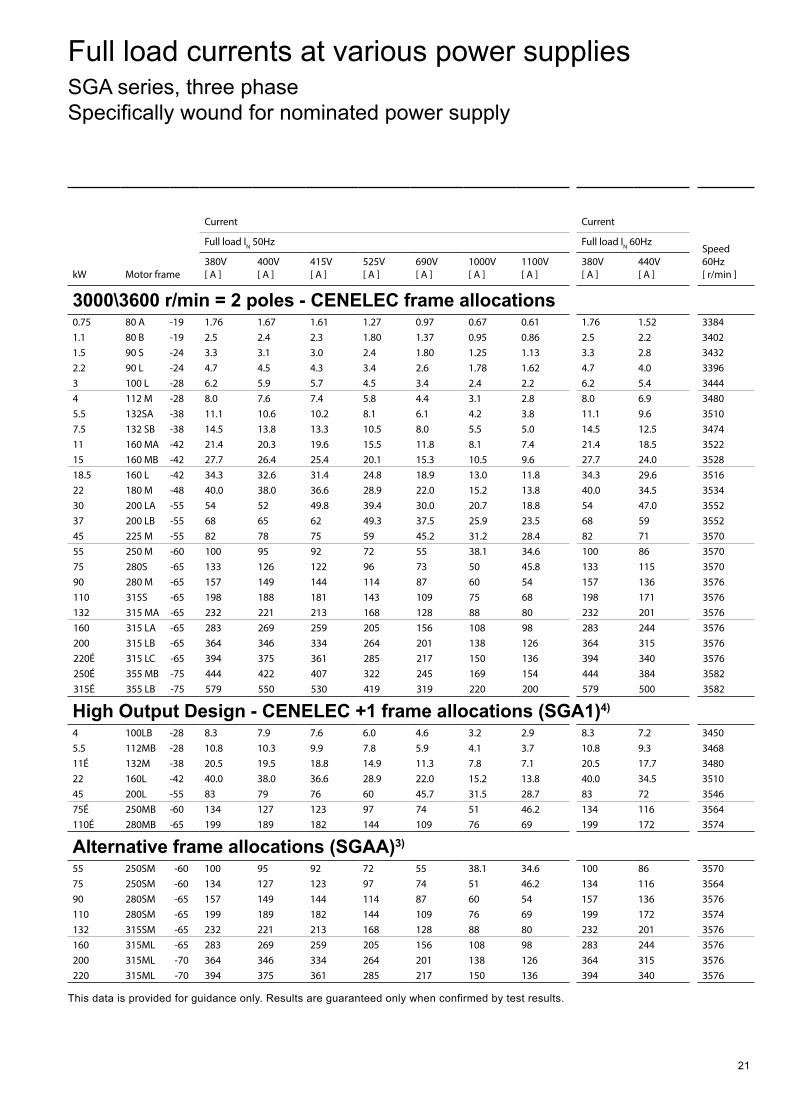
This data is provided for guidance only. Results are guaranteed only when confirmed by test results.
kW Motor frame
Current Current Speed 60Hz [ r/min ]
Full load IN 50Hz Full load IN 60Hz
380V [ A ]
400V [ A ]
415V [ A ]
525V [ A ]
690V [ A ]
1000V [ A ]
1100V [ A ]
380V [ A ]
440V [ A ]
3000\3600 r/min = 2 poles - CENELEC frame allocations0.75 80 A -19 1.76 1.67 1.61 1.27 0.97 0.67 0.61 1.76 1.52 33841.1 80 B -19 2.5 2.4 2.3 1.80 1.37 0.95 0.86 2.5 2.2 34021.5 90 S -24 3.3 3.1 3.0 2.4 1.80 1.25 1.13 3.3 2.8 34322.2 90 L -24 4.7 4.5 4.3 3.4 2.6 1.78 1.62 4.7 4.0 33963 100 L -28 6.2 5.9 5.7 4.5 3.4 2.4 2.2 6.2 5.4 34444 112 M -28 8.0 7.6 7.4 5.8 4.4 3.1 2.8 8.0 6.9 34805.5 132SA -38 11.1 10.6 10.2 8.1 6.1 4.2 3.8 11.1 9.6 35107.5 132 SB -38 14.5 13.8 13.3 10.5 8.0 5.5 5.0 14.5 12.5 347411 160 MA -42 21.4 20.3 19.6 15.5 11.8 8.1 7.4 21.4 18.5 352215 160 MB -42 27.7 26.4 25.4 20.1 15.3 10.5 9.6 27.7 24.0 352818.5 160 L -42 34.3 32.6 31.4 24.8 18.9 13.0 11.8 34.3 29.6 351622 180 M -48 40.0 38.0 36.6 28.9 22.0 15.2 13.8 40.0 34.5 353430 200 LA -55 54 52 49.8 39.4 30.0 20.7 18.8 54 47.0 355237 200 LB -55 68 65 62 49.3 37.5 25.9 23.5 68 59 355245 225 M -55 82 78 75 59 45.2 31.2 28.4 82 71 357055 250 M -60 100 95 92 72 55 38.1 34.6 100 86 357075 280S -65 133 126 122 96 73 50 45.8 133 115 357090 280 M -65 157 149 144 114 87 60 54 157 136 3576110 315S -65 198 188 181 143 109 75 68 198 171 3576132 315 MA -65 232 221 213 168 128 88 80 232 201 3576160 315 LA -65 283 269 259 205 156 108 98 283 244 3576200 315 LB -65 364 346 334 264 201 138 126 364 315 3576220É 315 LC -65 394 375 361 285 217 150 136 394 340 3576250É 355 MB -75 444 422 407 322 245 169 154 444 384 3582315É 355 LB -75 579 550 530 419 319 220 200 579 500 3582
High Output Design - CENELEC +1 frame allocations (SGA1)4)
4 100LB -28 8.3 7.9 7.6 6.0 4.6 3.2 2.9 8.3 7.2 34505.5 112MB -28 10.8 10.3 9.9 7.8 5.9 4.1 3.7 10.8 9.3 346811É 132M -38 20.5 19.5 18.8 14.9 11.3 7.8 7.1 20.5 17.7 348022 160L -42 40.0 38.0 36.6 28.9 22.0 15.2 13.8 40.0 34.5 351045 200L -55 83 79 76 60 45.7 31.5 28.7 83 72 354675É 250MB -60 134 127 123 97 74 51 46.2 134 116 3564110É 280MB -65 199 189 182 144 109 76 69 199 172 3574
Alternative frame allocations (SGAA)3)
55 250SM -60 100 95 92 72 55 38.1 34.6 100 86 357075 250SM -60 134 127 123 97 74 51 46.2 134 116 356490 280SM -65 157 149 144 114 87 60 54 157 136 3576110 280SM -65 199 189 182 144 109 76 69 199 172 3574132 315SM -65 232 221 213 168 128 88 80 232 201 3576160 315ML -65 283 269 259 205 156 108 98 283 244 3576200 315ML -70 364 346 334 264 201 138 126 364 315 3576220 315ML -70 394 375 361 285 217 150 136 394 340 3576
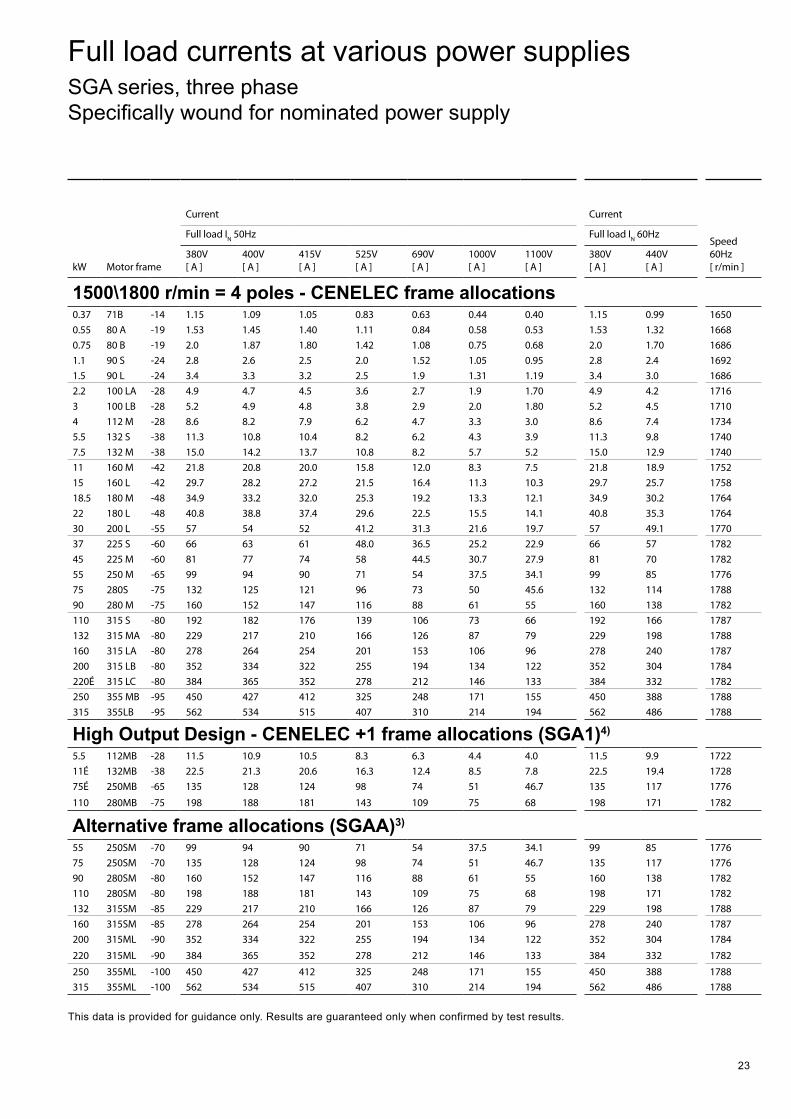
Full load currents at various power supplies SGA series, three phase Specifically wound for nominated power supply
22
Performance data SGA series, three phase 415V 50Hz IP55, F class insulation, B class temperature rise
kW Motor frame Speed [ r/min ]
Efficiency % Power factor, cos φ Current
tE timeÊ [ sec ]
Torque
Moment of inertia J=¼GD² [ kg m² ]
Weight of foot mount motor [ kg ]
at % full load at % full loadFull load IN [ A ]
Locked rotor lL/IN
Full load TN [ Nm ]
Locked rotor TL/TN
Break down TB/TN 125 100 75 50 125 100 75 50
1500 r/min = 4 poles - CENELEC frame allocations0.37 71B -14 1375 70.4 72.2 71.6 67.5 0.76 0.69 0.59 0.46 1.05 4.5 35 2.6 3.3 2.7 0.001 150.55 80 A -19 1390 71.0 72.1 72.2 68.5 0.80 0.75 0.67 0.54 1.40 4.8 25 3.8 2.5 2.6 0.002 190.75 80 B -19 1405 73.7 75.7 75.9 73.3 0.81 0.76 0.68 0.55 1.80 5.0 24 5.1 2.4 2.5 0.002 201.1 90 S -24 1410 75.2 77.4 77.9 75.1 0.83 0.78 0.71 0.58 2.5 5.4 10 7.4 2.8 2.4 0.002 251.5 90 L -24 1405 76.7 79.4 80.7 79.8 0.87 0.85 0.81 0.72 3.2 5.7 12 10.2 1.8 2.4 0.003 282.2 100 LA -28 1430 81.4 82.6 82.9 81.2 0.86 0.83 0.76 0.65 4.5 6.6 11 14.7 2.8 3.5 0.005 363 100 LB -28 1425 81.1 82.6 83.2 81.5 0.87 0.85 0.78 0.66 6.0 8.3 7 20.1 2.9 3.1 0.007 394 112 M -28 1445 84.4 85.3 85.1 83.0 0.86 0.82 0.76 0.64 7.9 7.6 7 26.4 3.1 3.5 0.010 455.5 132 S -38 1450 86.0 87.0 87.1 85.9 0.87 0.85 0.81 0.71 10.4 6.8 11 36.2 2.3 3.1 0.021 727.5 132 M -38 1450 87.0 88.1 88.4 87.4 0.88 0.87 0.83 0.74 13.7 7.5 9 49.4 2.6 2.9 0.030 8411 160 M -42 1460 88.4 89.2 89.3 87.9 0.86 0.85 0.83 0.75 20.0 6.9 12 72 2.0 2.8 0.075 13015 160 L -42 1465 89.3 90.2 90.1 88.8 0.87 0.86 0.83 0.76 27.2 7.2 10 98 2.3 2.9 0.092 14518.5 180 M -48 1470 90.2 90.7 90.6 89.2 0.90 0.89 0.86 0.77 32.0 7.0 17 120 2.1 3.0 0.139 18022 180 L -48 1470 91.2 91.8 91.9 90.8 0.91 0.89 0.85 0.76 37.4 7.7 14 143 2.2 3.5 0.158 20030 200 L -55 1475 91.2 91.4 91.1 89.5 0.92 0.87 0.84 0.76 52 7.5 20 194 2.2 3.1 0.262 26037 225 S -60 1485 93.3 93.6 93.4 92.2 0.91 0.89 0.89 0.84 61 7.2 20 238 1.8 2.9 0.406 31045 225 M -60 1485 93.5 93.7 93.4 92.2 0.91 0.90 0.88 0.82 74 7.6 7 289 1.9 2.9 0.469 34055 250 M -65 1480 93.9 94.1 93.9 92.7 0.91 0.90 0.89 0.83 90 8.2 10 355 2.4 3.1 0.66 40575 280S -75 1490 95.2 95.0 94.6 93.2 0.95 0.91 0.88 0.78 121 7.7 20 481 2.5 3.2 1.12 56590 280 M -75 1485 94.9 94.9 94.7 93.6 0.90 0.90 0.89 0.84 147 7.3 20 579 2.5 3.3 1.46 665110 315 S -80 1489 94.8 94.6 94.1 92.4 0.93 0.92 0.92 0.84 176 8.2 - 706 2.3 2.8 3.11 1000132 315 MA -80 1490 95.2 95.0 94.4 92.9 0.92 0.92 0.90 0.85 210 8.1 - 846 2.2 2.7 3.62 1100160 315 LA -80 1489 95.7 95.5 95.1 93.9 0.92 0.92 0.89 0.84 254 8.2 - 1026 2.3 2.9 4.13 1140200 315 LB -80 1487 95.8 95.5 95.3 94.2 0.92 0.91 0.88 0.80 322 7.5 - 1285 2.7 3.2 4.73 1190220É 315 LC -80 1485 95.8 95.6 95.3 94.4 0.92 0.91 0.89 0.83 352 6.9 - 1415 2.5 2.9 4.8 1230250 355 MB -95 1490 95.8 95.7 95.3 94.2 0.89 0.88 0.87 0.83 412 7.0 - 1602 2.1 3.0 6.5 1800315 355LB -95 1490 95.9 95.9 95.6 94.6 0.88 0.89 0.88 0.84 515 5.5 - 2019 1.5 2.9 8.2 1940
High Output Design - CENELEC +1 frame allocations (SGA1)4)
5.5 112MB -28 1435 84.7 86.3 86.3 84.7 0.88 0.84 0.82 0.66 10.5 6.6 - 36.6 2.3 2.4 0.0116 5311É 132MB -38 1440 88.0 89.2 89.8 89.3 0.86 0.83 0.78 0.68 20.6 7.8 - 73 1.9 3.0 0.034 8175É 250MB -65 1480 94.1 94.5 94.7 94.1 0.92 0.89 0.89 0.83 124 7.4 - 484 2.5 2.4 0.90 450
110 280MB -75 1485 95.2 95.5 95.4 94.6 0.90 0.89 0.87 0.80 181 7.6 - 707 2.0 3.2 1.78 720
Alternative frame allocations (SGAA)3)
55 250SM -70 1480 93.9 94.1 93.9 92.7 0.91 0.90 0.89 0.83 90 8.2 10 355 2.4 3.1 0.66 40575 250SM -70 1480 94.1 94.5 94.7 94.1 0.92 0.89 0.89 0.83 124 7.4 - 484 2.5 2.4 0.90 45090 280SM -80 1485 94.9 94.9 94.7 93.6 0.90 0.90 0.89 0.84 147 7.3 20 579 2.5 3.3 1.46 662110 280SM -80 1485 95.2 95.5 95.4 94.6 0.90 0.89 0.87 0.80 181 7.6 - 707 2.0 3.2 1.78 720132 315SM -85 1490 95.2 95.0 94.4 92.9 0.92 0.92 0.90 0.85 210 8.1 - 846 2.2 2.7 3.62 1100160 315SM -85 1489 95.7 95.5 95.1 93.9 0.92 0.92 0.89 0.84 254 8.2 - 1026 2.3 2.9 4.13 1140200 315ML -90 1487 95.8 95.5 95.3 94.2 0.92 0.91 0.88 0.80 322 7.5 - 1285 2.7 3.2 4.73 1225
220 315ML -90 1485 95.8 95.6 95.3 94.4 0.92 0.91 0.89 0.83 352 6.9 - 1415 2.5 2.9 4.80 1230
250 355ML -100 1490 95.8 95.7 95.3 94.2 0.89 0.88 0.87 0.83 412 7.0 - 1602 2.1 3.0 6.5 1800315 355ML -100 1490 95.9 95.9 95.6 94.6 0.88 0.89 0.88 0.84 515 5.5 - 2019 1.5 2.9 8.2 1940
This data is provided for guidance only. Results are guaranteed only when confirmed by test results. 1) F Class temperature rise2) tE time applies to Ex e motors only and is explained in the hazardous
areas section.3) The SGAA series are supplied as standard in South Africa.4) The output of these motors is one step higher than the basic design with
rated outputs in accordance with CENELEC.
23
kW Motor frame Speed [ r/min ]
Efficiency % Power factor, cos φ Current
tE timeÊ [ sec ]
Torque
Moment of inertia J=¼GD² [ kg m² ]
Weight of foot mount motor [ kg ]
at % full load at % full loadFull load IN [ A ]
Locked rotor lL/IN
Full load TN [ Nm ]
Locked rotor TL/TN
Break down TB/TN 125 100 75 50 125 100 75 50
1500 r/min = 4 poles - CENELEC frame allocations0.37 71B -14 1375 70.4 72.2 71.6 67.5 0.76 0.69 0.59 0.46 1.05 4.5 35 2.6 3.3 2.7 0.001 150.55 80 A -19 1390 71.0 72.1 72.2 68.5 0.80 0.75 0.67 0.54 1.40 4.8 25 3.8 2.5 2.6 0.002 190.75 80 B -19 1405 73.7 75.7 75.9 73.3 0.81 0.76 0.68 0.55 1.80 5.0 24 5.1 2.4 2.5 0.002 201.1 90 S -24 1410 75.2 77.4 77.9 75.1 0.83 0.78 0.71 0.58 2.5 5.4 10 7.4 2.8 2.4 0.002 251.5 90 L -24 1405 76.7 79.4 80.7 79.8 0.87 0.85 0.81 0.72 3.2 5.7 12 10.2 1.8 2.4 0.003 282.2 100 LA -28 1430 81.4 82.6 82.9 81.2 0.86 0.83 0.76 0.65 4.5 6.6 11 14.7 2.8 3.5 0.005 363 100 LB -28 1425 81.1 82.6 83.2 81.5 0.87 0.85 0.78 0.66 6.0 8.3 7 20.1 2.9 3.1 0.007 394 112 M -28 1445 84.4 85.3 85.1 83.0 0.86 0.82 0.76 0.64 7.9 7.6 7 26.4 3.1 3.5 0.010 455.5 132 S -38 1450 86.0 87.0 87.1 85.9 0.87 0.85 0.81 0.71 10.4 6.8 11 36.2 2.3 3.1 0.021 727.5 132 M -38 1450 87.0 88.1 88.4 87.4 0.88 0.87 0.83 0.74 13.7 7.5 9 49.4 2.6 2.9 0.030 8411 160 M -42 1460 88.4 89.2 89.3 87.9 0.86 0.85 0.83 0.75 20.0 6.9 12 72 2.0 2.8 0.075 13015 160 L -42 1465 89.3 90.2 90.1 88.8 0.87 0.86 0.83 0.76 27.2 7.2 10 98 2.3 2.9 0.092 14518.5 180 M -48 1470 90.2 90.7 90.6 89.2 0.90 0.89 0.86 0.77 32.0 7.0 17 120 2.1 3.0 0.139 18022 180 L -48 1470 91.2 91.8 91.9 90.8 0.91 0.89 0.85 0.76 37.4 7.7 14 143 2.2 3.5 0.158 20030 200 L -55 1475 91.2 91.4 91.1 89.5 0.92 0.87 0.84 0.76 52 7.5 20 194 2.2 3.1 0.262 26037 225 S -60 1485 93.3 93.6 93.4 92.2 0.91 0.89 0.89 0.84 61 7.2 20 238 1.8 2.9 0.406 31045 225 M -60 1485 93.5 93.7 93.4 92.2 0.91 0.90 0.88 0.82 74 7.6 7 289 1.9 2.9 0.469 34055 250 M -65 1480 93.9 94.1 93.9 92.7 0.91 0.90 0.89 0.83 90 8.2 10 355 2.4 3.1 0.66 40575 280S -75 1490 95.2 95.0 94.6 93.2 0.95 0.91 0.88 0.78 121 7.7 20 481 2.5 3.2 1.12 56590 280 M -75 1485 94.9 94.9 94.7 93.6 0.90 0.90 0.89 0.84 147 7.3 20 579 2.5 3.3 1.46 665110 315 S -80 1489 94.8 94.6 94.1 92.4 0.93 0.92 0.92 0.84 176 8.2 - 706 2.3 2.8 3.11 1000132 315 MA -80 1490 95.2 95.0 94.4 92.9 0.92 0.92 0.90 0.85 210 8.1 - 846 2.2 2.7 3.62 1100160 315 LA -80 1489 95.7 95.5 95.1 93.9 0.92 0.92 0.89 0.84 254 8.2 - 1026 2.3 2.9 4.13 1140200 315 LB -80 1487 95.8 95.5 95.3 94.2 0.92 0.91 0.88 0.80 322 7.5 - 1285 2.7 3.2 4.73 1190220É 315 LC -80 1485 95.8 95.6 95.3 94.4 0.92 0.91 0.89 0.83 352 6.9 - 1415 2.5 2.9 4.8 1230250 355 MB -95 1490 95.8 95.7 95.3 94.2 0.89 0.88 0.87 0.83 412 7.0 - 1602 2.1 3.0 6.5 1800315 355LB -95 1490 95.9 95.9 95.6 94.6 0.88 0.89 0.88 0.84 515 5.5 - 2019 1.5 2.9 8.2 1940
High Output Design - CENELEC +1 frame allocations (SGA1)4)
5.5 112MB -28 1435 84.7 86.3 86.3 84.7 0.88 0.84 0.82 0.66 10.5 6.6 - 36.6 2.3 2.4 0.0116 5311É 132MB -38 1440 88.0 89.2 89.8 89.3 0.86 0.83 0.78 0.68 20.6 7.8 - 73 1.9 3.0 0.034 8175É 250MB -65 1480 94.1 94.5 94.7 94.1 0.92 0.89 0.89 0.83 124 7.4 - 484 2.5 2.4 0.90 450
110 280MB -75 1485 95.2 95.5 95.4 94.6 0.90 0.89 0.87 0.80 181 7.6 - 707 2.0 3.2 1.78 720
Alternative frame allocations (SGAA)3)
55 250SM -70 1480 93.9 94.1 93.9 92.7 0.91 0.90 0.89 0.83 90 8.2 10 355 2.4 3.1 0.66 40575 250SM -70 1480 94.1 94.5 94.7 94.1 0.92 0.89 0.89 0.83 124 7.4 - 484 2.5 2.4 0.90 45090 280SM -80 1485 94.9 94.9 94.7 93.6 0.90 0.90 0.89 0.84 147 7.3 20 579 2.5 3.3 1.46 662110 280SM -80 1485 95.2 95.5 95.4 94.6 0.90 0.89 0.87 0.80 181 7.6 - 707 2.0 3.2 1.78 720132 315SM -85 1490 95.2 95.0 94.4 92.9 0.92 0.92 0.90 0.85 210 8.1 - 846 2.2 2.7 3.62 1100160 315SM -85 1489 95.7 95.5 95.1 93.9 0.92 0.92 0.89 0.84 254 8.2 - 1026 2.3 2.9 4.13 1140200 315ML -90 1487 95.8 95.5 95.3 94.2 0.92 0.91 0.88 0.80 322 7.5 - 1285 2.7 3.2 4.73 1225
220 315ML -90 1485 95.8 95.6 95.3 94.4 0.92 0.91 0.89 0.83 352 6.9 - 1415 2.5 2.9 4.80 1230
250 355ML -100 1490 95.8 95.7 95.3 94.2 0.89 0.88 0.87 0.83 412 7.0 - 1602 2.1 3.0 6.5 1800315 355ML -100 1490 95.9 95.9 95.6 94.6 0.88 0.89 0.88 0.84 515 5.5 - 2019 1.5 2.9 8.2 1940
kW Motor frame
Current Current
Speed 60Hz [ r/min ]
Full load IN 50Hz Full load IN 60Hz
380V [ A ]
400V [ A ]
415V [ A ]
525V [ A ]
690V [ A ]
1000V [ A ]
1100V [ A ]
380V [ A ]
440V [ A ]
1500\1800 r/min = 4 poles - CENELEC frame allocations0.37 71B -14 1.15 1.09 1.05 0.83 0.63 0.44 0.40 1.15 0.99 16500.55 80 A -19 1.53 1.45 1.40 1.11 0.84 0.58 0.53 1.53 1.32 16680.75 80 B -19 2.0 1.87 1.80 1.42 1.08 0.75 0.68 2.0 1.70 16861.1 90 S -24 2.8 2.6 2.5 2.0 1.52 1.05 0.95 2.8 2.4 16921.5 90 L -24 3.4 3.3 3.2 2.5 1.9 1.31 1.19 3.4 3.0 16862.2 100 LA -28 4.9 4.7 4.5 3.6 2.7 1.9 1.70 4.9 4.2 17163 100 LB -28 5.2 4.9 4.8 3.8 2.9 2.0 1.80 5.2 4.5 17104 112 M -28 8.6 8.2 7.9 6.2 4.7 3.3 3.0 8.6 7.4 17345.5 132 S -38 11.3 10.8 10.4 8.2 6.2 4.3 3.9 11.3 9.8 17407.5 132 M -38 15.0 14.2 13.7 10.8 8.2 5.7 5.2 15.0 12.9 174011 160 M -42 21.8 20.8 20.0 15.8 12.0 8.3 7.5 21.8 18.9 175215 160 L -42 29.7 28.2 27.2 21.5 16.4 11.3 10.3 29.7 25.7 175818.5 180 M -48 34.9 33.2 32.0 25.3 19.2 13.3 12.1 34.9 30.2 176422 180 L -48 40.8 38.8 37.4 29.6 22.5 15.5 14.1 40.8 35.3 176430 200 L -55 57 54 52 41.2 31.3 21.6 19.7 57 49.1 177037 225 S -60 66 63 61 48.0 36.5 25.2 22.9 66 57 178245 225 M -60 81 77 74 58 44.5 30.7 27.9 81 70 178255 250 M -65 99 94 90 71 54 37.5 34.1 99 85 177675 280S -75 132 125 121 96 73 50 45.6 132 114 178890 280 M -75 160 152 147 116 88 61 55 160 138 1782110 315 S -80 192 182 176 139 106 73 66 192 166 1787132 315 MA -80 229 217 210 166 126 87 79 229 198 1788160 315 LA -80 278 264 254 201 153 106 96 278 240 1787200 315 LB -80 352 334 322 255 194 134 122 352 304 1784220É 315 LC -80 384 365 352 278 212 146 133 384 332 1782250 355 MB -95 450 427 412 325 248 171 155 450 388 1788315 355LB -95 562 534 515 407 310 214 194 562 486 1788
High Output Design - CENELEC +1 frame allocations (SGA1)4)
5.5 112MB -28 11.5 10.9 10.5 8.3 6.3 4.4 4.0 11.5 9.9 172211É 132MB -38 22.5 21.3 20.6 16.3 12.4 8.5 7.8 22.5 19.4 172875É 250MB -65 135 128 124 98 74 51 46.7 135 117 1776
110 280MB -75 198 188 181 143 109 75 68 198 171 1782
Alternative frame allocations (SGAA)3)
55 250SM -70 99 94 90 71 54 37.5 34.1 99 85 177675 250SM -70 135 128 124 98 74 51 46.7 135 117 177690 280SM -80 160 152 147 116 88 61 55 160 138 1782110 280SM -80 198 188 181 143 109 75 68 198 171 1782132 315SM -85 229 217 210 166 126 87 79 229 198 1788160 315SM -85 278 264 254 201 153 106 96 278 240 1787200 315ML -90 352 334 322 255 194 134 122 352 304 1784
220 315ML -90 384 365 352 278 212 146 133 384 332 1782
250 355ML -100 450 427 412 325 248 171 155 450 388 1788315 355ML -100 562 534 515 407 310 214 194 562 486 1788
This data is provided for guidance only. Results are guaranteed only when confirmed by test results.
Full load currents at various power supplies SGA series, three phase Specifically wound for nominated power supply
24
kW Motor frame Speed [ r/min ]
Efficiency % Power factor, cos φ Current
tE timeÊ [ sec ]
Torque
Moment of inertia J=¼GD² [ kg m² ]
Weight of foot mount motor [ kg ]
at % full load at % full load Full load IN [ A ]
Locked rotor lL/IN
Full load TN [ Nm ]
Locked rotor TL/TN
Break down TB/TN 125 100 75 50 125 100 75 50
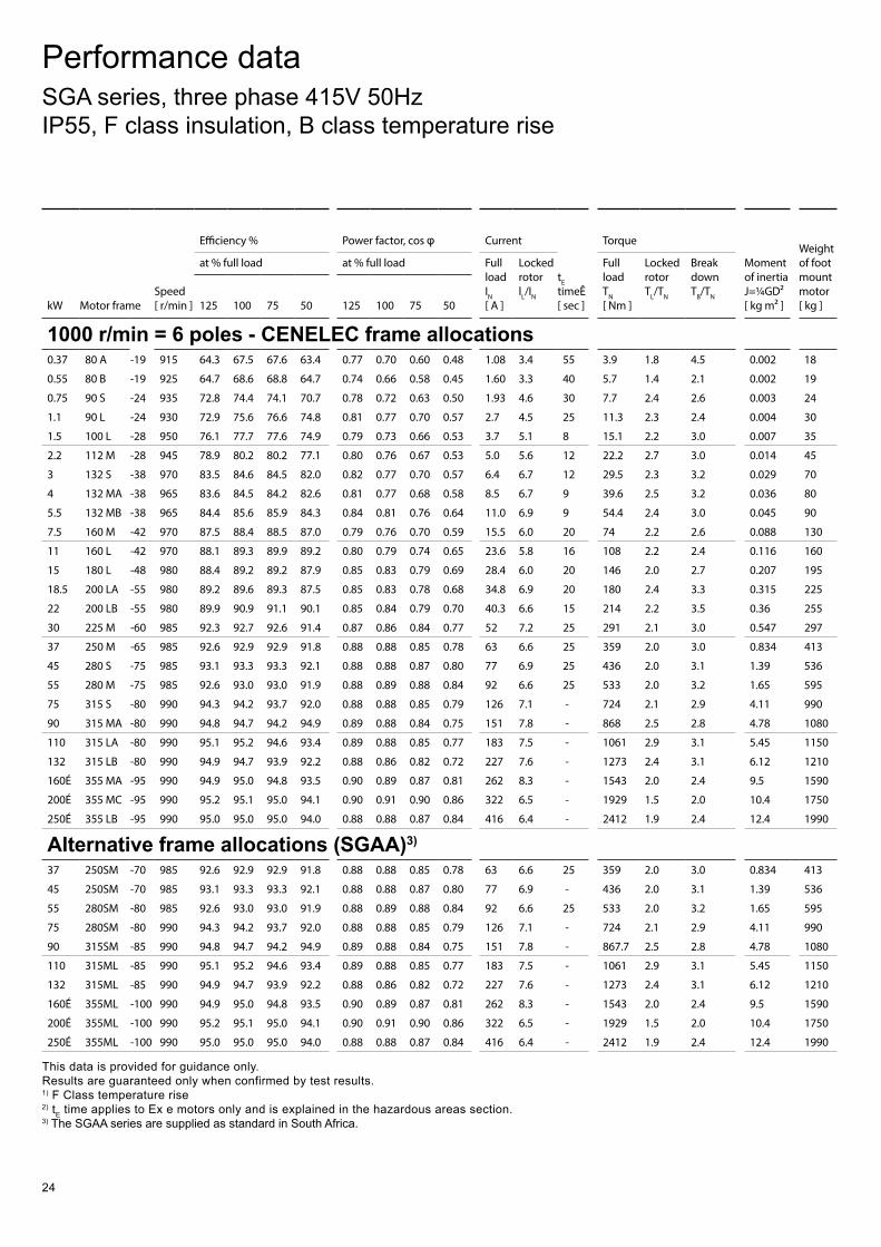
1000 r/min = 6 poles - CENELEC frame allocations0.37 80 A -19 915 64.3 67.5 67.6 63.4 0.77 0.70 0.60 0.48 1.08 3.4 55 3.9 1.8 4.5 0.002 18
0.55 80 B -19 925 64.7 68.6 68.8 64.7 0.74 0.66 0.58 0.45 1.60 3.3 40 5.7 1.4 2.1 0.002 19
0.75 90 S -24 935 72.8 74.4 74.1 70.7 0.78 0.72 0.63 0.50 1.93 4.6 30 7.7 2.4 2.6 0.003 24
1.1 90 L -24 930 72.9 75.6 76.6 74.8 0.81 0.77 0.70 0.57 2.7 4.5 25 11.3 2.3 2.4 0.004 30
1.5 100 L -28 950 76.1 77.7 77.6 74.9 0.79 0.73 0.66 0.53 3.7 5.1 8 15.1 2.2 3.0 0.007 35
2.2 112 M -28 945 78.9 80.2 80.2 77.1 0.80 0.76 0.67 0.53 5.0 5.6 12 22.2 2.7 3.0 0.014 45
3 132 S -38 970 83.5 84.6 84.5 82.0 0.82 0.77 0.70 0.57 6.4 6.7 12 29.5 2.3 3.2 0.029 70
4 132 MA -38 965 83.6 84.5 84.2 82.6 0.81 0.77 0.68 0.58 8.5 6.7 9 39.6 2.5 3.2 0.036 80
5.5 132 MB -38 965 84.4 85.6 85.9 84.3 0.84 0.81 0.76 0.64 11.0 6.9 9 54.4 2.4 3.0 0.045 90
7.5 160 M -42 970 87.5 88.4 88.5 87.0 0.79 0.76 0.70 0.59 15.5 6.0 20 74 2.2 2.6 0.088 130
11 160 L -42 970 88.1 89.3 89.9 89.2 0.80 0.79 0.74 0.65 23.6 5.8 16 108 2.2 2.4 0.116 160
15 180 L -48 980 88.4 89.2 89.2 87.9 0.85 0.83 0.79 0.69 28.4 6.0 20 146 2.0 2.7 0.207 195
18.5 200 LA -55 980 89.2 89.6 89.3 87.5 0.85 0.83 0.78 0.68 34.8 6.9 20 180 2.4 3.3 0.315 225
22 200 LB -55 980 89.9 90.9 91.1 90.1 0.85 0.84 0.79 0.70 40.3 6.6 15 214 2.2 3.5 0.36 255
30 225 M -60 985 92.3 92.7 92.6 91.4 0.87 0.86 0.84 0.77 52 7.2 25 291 2.1 3.0 0.547 297
37 250 M -65 985 92.6 92.9 92.9 91.8 0.88 0.88 0.85 0.78 63 6.6 25 359 2.0 3.0 0.834 413
45 280 S -75 985 93.1 93.3 93.3 92.1 0.88 0.88 0.87 0.80 77 6.9 25 436 2.0 3.1 1.39 536
55 280 M -75 985 92.6 93.0 93.0 91.9 0.88 0.89 0.88 0.84 92 6.6 25 533 2.0 3.2 1.65 595
75 315 S -80 990 94.3 94.2 93.7 92.0 0.88 0.88 0.85 0.79 126 7.1 - 724 2.1 2.9 4.11 990
90 315 MA -80 990 94.8 94.7 94.2 94.9 0.89 0.88 0.84 0.75 151 7.8 - 868 2.5 2.8 4.78 1080
110 315 LA -80 990 95.1 95.2 94.6 93.4 0.89 0.88 0.85 0.77 183 7.5 - 1061 2.9 3.1 5.45 1150
132 315 LB -80 990 94.9 94.7 93.9 92.2 0.88 0.86 0.82 0.72 227 7.6 - 1273 2.4 3.1 6.12 1210
160É 355 MA -95 990 94.9 95.0 94.8 93.5 0.90 0.89 0.87 0.81 262 8.3 - 1543 2.0 2.4 9.5 1590
200É 355 MC -95 990 95.2 95.1 95.0 94.1 0.90 0.91 0.90 0.86 322 6.5 - 1929 1.5 2.0 10.4 1750
250É 355 LB -95 990 95.0 95.0 95.0 94.0 0.88 0.88 0.87 0.84 416 6.4 - 2412 1.9 2.4 12.4 1990
Alternative frame allocations (SGAA)3)
37 250SM -70 985 92.6 92.9 92.9 91.8 0.88 0.88 0.85 0.78 63 6.6 25 359 2.0 3.0 0.834 413
45 250SM -70 985 93.1 93.3 93.3 92.1 0.88 0.88 0.87 0.80 77 6.9 - 436 2.0 3.1 1.39 536
55 280SM -80 985 92.6 93.0 93.0 91.9 0.88 0.89 0.88 0.84 92 6.6 25 533 2.0 3.2 1.65 595
75 280SM -80 990 94.3 94.2 93.7 92.0 0.88 0.88 0.85 0.79 126 7.1 - 724 2.1 2.9 4.11 990
90 315SM -85 990 94.8 94.7 94.2 94.9 0.89 0.88 0.84 0.75 151 7.8 - 867.7 2.5 2.8 4.78 1080
110 315ML -85 990 95.1 95.2 94.6 93.4 0.89 0.88 0.85 0.77 183 7.5 - 1061 2.9 3.1 5.45 1150
132 315ML -85 990 94.9 94.7 93.9 92.2 0.88 0.86 0.82 0.72 227 7.6 - 1273 2.4 3.1 6.12 1210
160É 355ML -100 990 94.9 95.0 94.8 93.5 0.90 0.89 0.87 0.81 262 8.3 - 1543 2.0 2.4 9.5 1590
200É 355ML -100 990 95.2 95.1 95.0 94.1 0.90 0.91 0.90 0.86 322 6.5 - 1929 1.5 2.0 10.4 1750
250É 355ML -100 990 95.0 95.0 95.0 94.0 0.88 0.88 0.87 0.84 416 6.4 - 2412 1.9 2.4 12.4 1990
This data is provided for guidance only. Results are guaranteed only when confirmed by test results. 1) F Class temperature rise2) tE time applies to Ex e motors only and is explained in the hazardous areas section.3) The SGAA series are supplied as standard in South Africa.
Performance data SGA series, three phase 415V 50Hz IP55, F class insulation, B class temperature rise
25
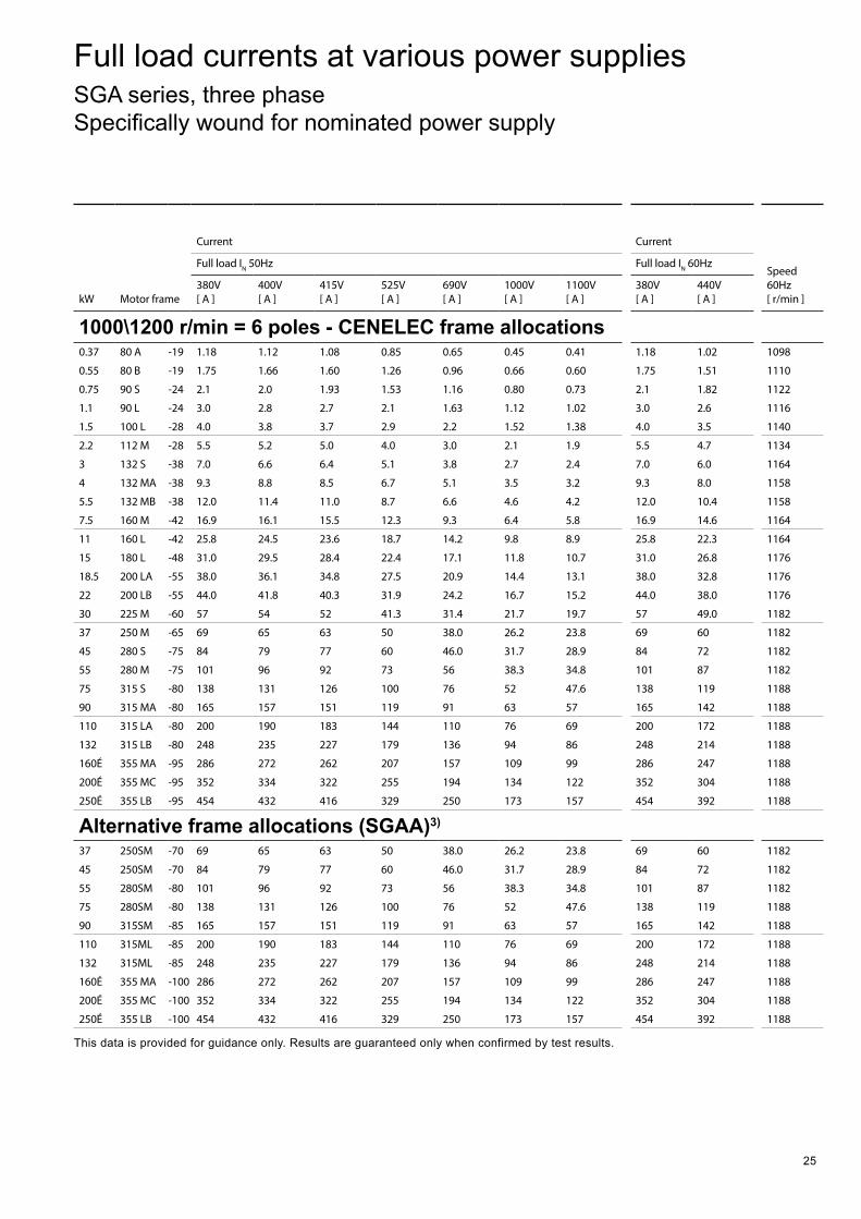
kW Motor frame
Current Current
Speed 60Hz [ r/min ]
Full load IN 50Hz Full load IN 60Hz
380V [ A ]
400V [ A ]
415V [ A ]
525V [ A ]
690V [ A ]
1000V [ A ]
1100V [ A ]
380V [ A ]
440V [ A ]
1000\1200 r/min = 6 poles - CENELEC frame allocations0.37 80 A -19 1.18 1.12 1.08 0.85 0.65 0.45 0.41 1.18 1.02 1098
0.55 80 B -19 1.75 1.66 1.60 1.26 0.96 0.66 0.60 1.75 1.51 1110
0.75 90 S -24 2.1 2.0 1.93 1.53 1.16 0.80 0.73 2.1 1.82 1122
1.1 90 L -24 3.0 2.8 2.7 2.1 1.63 1.12 1.02 3.0 2.6 1116
1.5 100 L -28 4.0 3.8 3.7 2.9 2.2 1.52 1.38 4.0 3.5 1140
2.2 112 M -28 5.5 5.2 5.0 4.0 3.0 2.1 1.9 5.5 4.7 1134
3 132 S -38 7.0 6.6 6.4 5.1 3.8 2.7 2.4 7.0 6.0 1164
4 132 MA -38 9.3 8.8 8.5 6.7 5.1 3.5 3.2 9.3 8.0 1158
5.5 132 MB -38 12.0 11.4 11.0 8.7 6.6 4.6 4.2 12.0 10.4 1158
7.5 160 M -42 16.9 16.1 15.5 12.3 9.3 6.4 5.8 16.9 14.6 1164
11 160 L -42 25.8 24.5 23.6 18.7 14.2 9.8 8.9 25.8 22.3 1164
15 180 L -48 31.0 29.5 28.4 22.4 17.1 11.8 10.7 31.0 26.8 1176
18.5 200 LA -55 38.0 36.1 34.8 27.5 20.9 14.4 13.1 38.0 32.8 1176
22 200 LB -55 44.0 41.8 40.3 31.9 24.2 16.7 15.2 44.0 38.0 1176
30 225 M -60 57 54 52 41.3 31.4 21.7 19.7 57 49.0 1182
37 250 M -65 69 65 63 50 38.0 26.2 23.8 69 60 1182
45 280 S -75 84 79 77 60 46.0 31.7 28.9 84 72 1182
55 280 M -75 101 96 92 73 56 38.3 34.8 101 87 1182
75 315 S -80 138 131 126 100 76 52 47.6 138 119 1188
90 315 MA -80 165 157 151 119 91 63 57 165 142 1188
110 315 LA -80 200 190 183 144 110 76 69 200 172 1188
132 315 LB -80 248 235 227 179 136 94 86 248 214 1188
160É 355 MA -95 286 272 262 207 157 109 99 286 247 1188
200É 355 MC -95 352 334 322 255 194 134 122 352 304 1188
250É 355 LB -95 454 432 416 329 250 173 157 454 392 1188
Alternative frame allocations (SGAA)3)
37 250SM -70 69 65 63 50 38.0 26.2 23.8 69 60 1182
45 250SM -70 84 79 77 60 46.0 31.7 28.9 84 72 1182
55 280SM -80 101 96 92 73 56 38.3 34.8 101 87 1182
75 280SM -80 138 131 126 100 76 52 47.6 138 119 1188
90 315SM -85 165 157 151 119 91 63 57 165 142 1188
110 315ML -85 200 190 183 144 110 76 69 200 172 1188
132 315ML -85 248 235 227 179 136 94 86 248 214 1188
160É 355 MA -100 286 272 262 207 157 109 99 286 247 1188
200É 355 MC -100 352 334 322 255 194 134 122 352 304 1188
250É 355 LB -100 454 432 416 329 250 173 157 454 392 1188
This data is provided for guidance only. Results are guaranteed only when confirmed by test results.
Full load currents at various power supplies SGA series, three phase Specifically wound for nominated power supply
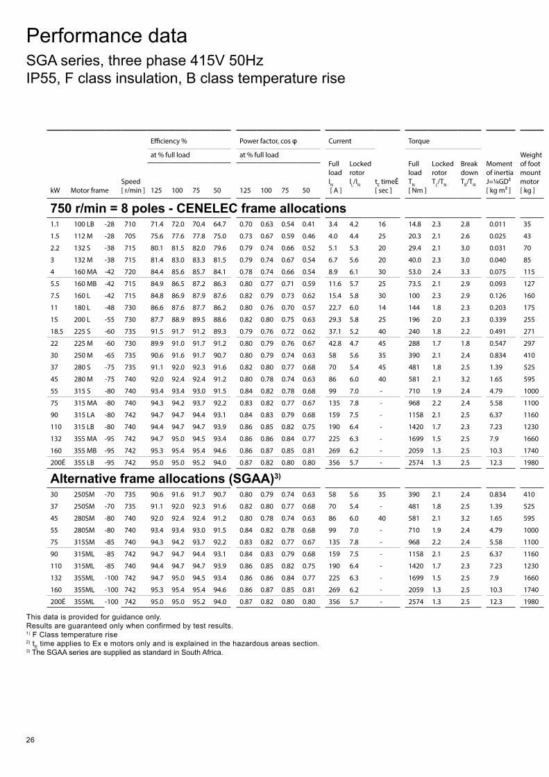
26
kW Motor frame Speed [ r/min ]
Efficiency % Power factor, cos φ Current
tE timeÊ [ sec ]
Torque
Moment of inertia J=¼GD² [ kg m² ]
Weight of foot mount motor [ kg ]
at % full load at % full loadFull load IN [ A ]
Locked rotor lL/IN
Full load TN [ Nm ]
Locked rotor TL/TN
Break down TB/TN
125 100 75 50 125 100 75 50
750 r/min = 8 poles - CENELEC frame allocations1.1 100 LB -28 710 71.4 72.0 70.4 64.7 0.70 0.63 0.54 0.41 3.4 4.2 16 14.8 2.3 2.8 0.011 35
1.5 112 M -28 705 75.6 77.6 77.8 75.0 0.73 0.67 0.59 0.46 4.0 4.4 25 20.3 2.1 2.6 0.025 43
2.2 132 S -38 715 80.1 81.5 82.0 79.6 0.79 0.74 0.66 0.52 5.1 5.3 20 29.4 2.1 3.0 0.031 70
3 132 M -38 715 81.4 83.0 83.3 81.5 0.79 0.74 0.67 0.54 6.7 5.6 20 40.0 2.3 3.0 0.040 85
4 160 MA -42 720 84.4 85.6 85.7 84.1 0.78 0.74 0.66 0.54 8.9 6.1 30 53.0 2.4 3.3 0.075 115
5.5 160 MB -42 715 84.9 86.5 87.2 86.3 0.80 0.77 0.71 0.59 11.6 5.7 25 73.5 2.1 2.9 0.093 127
7.5 160 L -42 715 84.8 86.9 87.9 87.6 0.82 0.79 0.73 0.62 15.4 5.8 30 100 2.3 2.9 0.126 160
11 180 L -48 730 86.6 87.6 87.7 86.2 0.80 0.76 0.70 0.57 22.7 6.0 14 144 1.8 2.3 0.203 175
15 200 L -55 730 87.7 88.9 89.5 88.6 0.82 0.80 0.75 0.63 29.3 5.8 25 196 2.0 2.3 0.339 255
18.5 225 S -60 735 91.5 91.7 91.2 89.3 0.79 0.76 0.72 0.62 37.1 5.2 40 240 1.8 2.2 0.491 271
22 225 M -60 730 89.9 91.0 91.7 91.2 0.80 0.79 0.76 0.67 42.8 4.7 45 288 1.7 1.8 0.547 297
30 250 M -65 735 90.6 91.6 91.7 90.7 0.80 0.79 0.74 0.63 58 5.6 35 390 2.1 2.4 0.834 410
37 280 S -75 735 91.1 92.0 92.3 91.6 0.82 0.80 0.77 0.68 70 5.4 45 481 1.8 2.5 1.39 525
45 280 M -75 740 92.0 92.4 92.4 91.2 0.80 0.78 0.74 0.63 86 6.0 40 581 2.1 3.2 1.65 595
55 315 S -80 740 93.4 93.4 93.0 91.5 0.84 0.82 0.78 0.68 99 7.0 - 710 1.9 2.4 4.79 1000
75 315 MA -80 740 94.3 94.2 93.7 92.2 0.83 0.82 0.77 0.67 135 7.8 - 968 2.2 2.4 5.58 1100
90 315 LA -80 742 94.7 94.7 94.4 93.1 0.84 0.83 0.79 0.68 159 7.5 - 1158 2.1 2.5 6.37 1160
110 315 LB -80 740 94.4 94.7 94.7 93.9 0.86 0.85 0.82 0.75 190 6.4 - 1420 1.7 2.3 7.23 1230
132 355 MA -95 742 94.7 95.0 94.5 93.4 0.86 0.86 0.84 0.77 225 6.3 - 1699 1.5 2.5 7.9 1660
160 355 MB -95 742 95.3 95.4 95.4 94.6 0.86 0.87 0.85 0.81 269 6.2 - 2059 1.3 2.5 10.3 1740
200É 355 LB -95 742 95.0 95.0 95.2 94.0 0.87 0.82 0.80 0.80 356 5.7 - 2574 1.3 2.5 12.3 1980
Alternative frame allocations (SGAA)3)
30 250SM -70 735 90.6 91.6 91.7 90.7 0.80 0.79 0.74 0.63 58 5.6 35 390 2.1 2.4 0.834 410
37 250SM -70 735 91.1 92.0 92.3 91.6 0.82 0.80 0.77 0.68 70 5.4 - 481 1.8 2.5 1.39 525
45 280SM -80 740 92.0 92.4 92.4 91.2 0.80 0.78 0.74 0.63 86 6.0 40 581 2.1 3.2 1.65 595
55 280SM -80 740 93.4 93.4 93.0 91.5 0.84 0.82 0.78 0.68 99 7.0 - 710 1.9 2.4 4.79 1000
75 315SM -85 740 94.3 94.2 93.7 92.2 0.83 0.82 0.77 0.67 135 7.8 - 968 2.2 2.4 5.58 1100
90 315ML -85 742 94.7 94.7 94.4 93.1 0.84 0.83 0.79 0.68 159 7.5 - 1158 2.1 2.5 6.37 1160
110 315ML -85 740 94.4 94.7 94.7 93.9 0.86 0.85 0.82 0.75 190 6.4 - 1420 1.7 2.3 7.23 1230
132 355ML -100 742 94.7 95.0 94.5 93.4 0.86 0.86 0.84 0.77 225 6.3 - 1699 1.5 2.5 7.9 1660
160 355ML -100 742 95.3 95.4 95.4 94.6 0.86 0.87 0.85 0.81 269 6.2 - 2059 1.3 2.5 10.3 1740
200É 355ML -100 742 95.0 95.0 95.2 94.0 0.87 0.82 0.80 0.80 356 5.7 - 2574 1.3 2.5 12.3 1980
This data is provided for guidance only. Results are guaranteed only when confirmed by test results. 1) F Class temperature rise2) tE time applies to Ex e motors only and is explained in the hazardous areas section.3) The SGAA series are supplied as standard in South Africa.
Performance data SGA series, three phase 415V 50Hz IP55, F class insulation, B class temperature rise
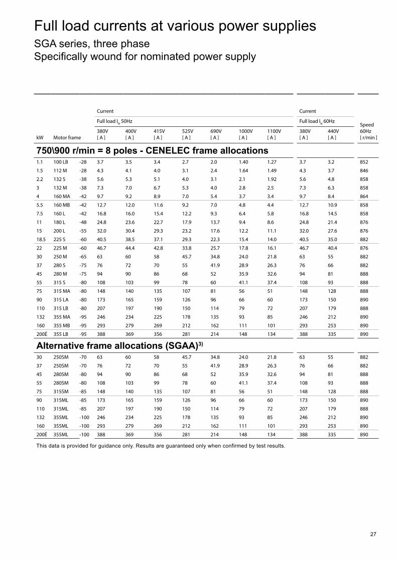
27
kW Motor frame Speed [ r/min ]
Efficiency % Power factor, cos φ Current
tE timeÊ [ sec ]
Torque
Moment of inertia J=¼GD² [ kg m² ]
Weight of foot mount motor [ kg ]
at % full load at % full loadFull load IN [ A ]
Locked rotor lL/IN
Full load TN [ Nm ]
Locked rotor TL/TN
Break down TB/TN
125 100 75 50 125 100 75 50
750 r/min = 8 poles - CENELEC frame allocations1.1 100 LB -28 710 71.4 72.0 70.4 64.7 0.70 0.63 0.54 0.41 3.4 4.2 16 14.8 2.3 2.8 0.011 35
1.5 112 M -28 705 75.6 77.6 77.8 75.0 0.73 0.67 0.59 0.46 4.0 4.4 25 20.3 2.1 2.6 0.025 43
2.2 132 S -38 715 80.1 81.5 82.0 79.6 0.79 0.74 0.66 0.52 5.1 5.3 20 29.4 2.1 3.0 0.031 70
3 132 M -38 715 81.4 83.0 83.3 81.5 0.79 0.74 0.67 0.54 6.7 5.6 20 40.0 2.3 3.0 0.040 85
4 160 MA -42 720 84.4 85.6 85.7 84.1 0.78 0.74 0.66 0.54 8.9 6.1 30 53.0 2.4 3.3 0.075 115
5.5 160 MB -42 715 84.9 86.5 87.2 86.3 0.80 0.77 0.71 0.59 11.6 5.7 25 73.5 2.1 2.9 0.093 127
7.5 160 L -42 715 84.8 86.9 87.9 87.6 0.82 0.79 0.73 0.62 15.4 5.8 30 100 2.3 2.9 0.126 160
11 180 L -48 730 86.6 87.6 87.7 86.2 0.80 0.76 0.70 0.57 22.7 6.0 14 144 1.8 2.3 0.203 175
15 200 L -55 730 87.7 88.9 89.5 88.6 0.82 0.80 0.75 0.63 29.3 5.8 25 196 2.0 2.3 0.339 255
18.5 225 S -60 735 91.5 91.7 91.2 89.3 0.79 0.76 0.72 0.62 37.1 5.2 40 240 1.8 2.2 0.491 271
22 225 M -60 730 89.9 91.0 91.7 91.2 0.80 0.79 0.76 0.67 42.8 4.7 45 288 1.7 1.8 0.547 297
30 250 M -65 735 90.6 91.6 91.7 90.7 0.80 0.79 0.74 0.63 58 5.6 35 390 2.1 2.4 0.834 410
37 280 S -75 735 91.1 92.0 92.3 91.6 0.82 0.80 0.77 0.68 70 5.4 45 481 1.8 2.5 1.39 525
45 280 M -75 740 92.0 92.4 92.4 91.2 0.80 0.78 0.74 0.63 86 6.0 40 581 2.1 3.2 1.65 595
55 315 S -80 740 93.4 93.4 93.0 91.5 0.84 0.82 0.78 0.68 99 7.0 - 710 1.9 2.4 4.79 1000
75 315 MA -80 740 94.3 94.2 93.7 92.2 0.83 0.82 0.77 0.67 135 7.8 - 968 2.2 2.4 5.58 1100
90 315 LA -80 742 94.7 94.7 94.4 93.1 0.84 0.83 0.79 0.68 159 7.5 - 1158 2.1 2.5 6.37 1160
110 315 LB -80 740 94.4 94.7 94.7 93.9 0.86 0.85 0.82 0.75 190 6.4 - 1420 1.7 2.3 7.23 1230
132 355 MA -95 742 94.7 95.0 94.5 93.4 0.86 0.86 0.84 0.77 225 6.3 - 1699 1.5 2.5 7.9 1660
160 355 MB -95 742 95.3 95.4 95.4 94.6 0.86 0.87 0.85 0.81 269 6.2 - 2059 1.3 2.5 10.3 1740
200É 355 LB -95 742 95.0 95.0 95.2 94.0 0.87 0.82 0.80 0.80 356 5.7 - 2574 1.3 2.5 12.3 1980
Alternative frame allocations (SGAA)3)
30 250SM -70 735 90.6 91.6 91.7 90.7 0.80 0.79 0.74 0.63 58 5.6 35 390 2.1 2.4 0.834 410
37 250SM -70 735 91.1 92.0 92.3 91.6 0.82 0.80 0.77 0.68 70 5.4 - 481 1.8 2.5 1.39 525
45 280SM -80 740 92.0 92.4 92.4 91.2 0.80 0.78 0.74 0.63 86 6.0 40 581 2.1 3.2 1.65 595
55 280SM -80 740 93.4 93.4 93.0 91.5 0.84 0.82 0.78 0.68 99 7.0 - 710 1.9 2.4 4.79 1000
75 315SM -85 740 94.3 94.2 93.7 92.2 0.83 0.82 0.77 0.67 135 7.8 - 968 2.2 2.4 5.58 1100
90 315ML -85 742 94.7 94.7 94.4 93.1 0.84 0.83 0.79 0.68 159 7.5 - 1158 2.1 2.5 6.37 1160
110 315ML -85 740 94.4 94.7 94.7 93.9 0.86 0.85 0.82 0.75 190 6.4 - 1420 1.7 2.3 7.23 1230
132 355ML -100 742 94.7 95.0 94.5 93.4 0.86 0.86 0.84 0.77 225 6.3 - 1699 1.5 2.5 7.9 1660
160 355ML -100 742 95.3 95.4 95.4 94.6 0.86 0.87 0.85 0.81 269 6.2 - 2059 1.3 2.5 10.3 1740
200É 355ML -100 742 95.0 95.0 95.2 94.0 0.87 0.82 0.80 0.80 356 5.7 - 2574 1.3 2.5 12.3 1980
kW Motor frame
Current Current
Speed 60Hz [ r/min ]
Full load IN 50Hz Full load IN 60Hz
380V [ A ]
400V [ A ]
415V [ A ]
525V [ A ]
690V [ A ]
1000V [ A ]
1100V [ A ]
380V [ A ]
440V [ A ]
750\900 r/min = 8 poles - CENELEC frame allocations1.1 100 LB -28 3.7 3.5 3.4 2.7 2.0 1.40 1.27 3.7 3.2 852
1.5 112 M -28 4.3 4.1 4.0 3.1 2.4 1.64 1.49 4.3 3.7 846
2.2 132 S -38 5.6 5.3 5.1 4.0 3.1 2.1 1.92 5.6 4.8 858
3 132 M -38 7.3 7.0 6.7 5.3 4.0 2.8 2.5 7.3 6.3 858
4 160 MA -42 9.7 9.2 8.9 7.0 5.4 3.7 3.4 9.7 8.4 864
5.5 160 MB -42 12.7 12.0 11.6 9.2 7.0 4.8 4.4 12.7 10.9 858
7.5 160 L -42 16.8 16.0 15.4 12.2 9.3 6.4 5.8 16.8 14.5 858
11 180 L -48 24.8 23.6 22.7 17.9 13.7 9.4 8.6 24.8 21.4 876
15 200 L -55 32.0 30.4 29.3 23.2 17.6 12.2 11.1 32.0 27.6 876
18.5 225 S -60 40.5 38.5 37.1 29.3 22.3 15.4 14.0 40.5 35.0 882
22 225 M -60 46.7 44.4 42.8 33.8 25.7 17.8 16.1 46.7 40.4 876
30 250 M -65 63 60 58 45.7 34.8 24.0 21.8 63 55 882
37 280 S -75 76 72 70 55 41.9 28.9 26.3 76 66 882
45 280 M -75 94 90 86 68 52 35.9 32.6 94 81 888
55 315 S -80 108 103 99 78 60 41.1 37.4 108 93 888
75 315 MA -80 148 140 135 107 81 56 51 148 128 888
90 315 LA -80 173 165 159 126 96 66 60 173 150 890
110 315 LB -80 207 197 190 150 114 79 72 207 179 888
132 355 MA -95 246 234 225 178 135 93 85 246 212 890
160 355 MB -95 293 279 269 212 162 111 101 293 253 890
200É 355 LB -95 388 369 356 281 214 148 134 388 335 890
Alternative frame allocations (SGAA)3)
30 250SM -70 63 60 58 45.7 34.8 24.0 21.8 63 55 882
37 250SM -70 76 72 70 55 41.9 28.9 26.3 76 66 882
45 280SM -80 94 90 86 68 52 35.9 32.6 94 81 888
55 280SM -80 108 103 99 78 60 41.1 37.4 108 93 888
75 315SM -85 148 140 135 107 81 56 51 148 128 888
90 315ML -85 173 165 159 126 96 66 60 173 150 890
110 315ML -85 207 197 190 150 114 79 72 207 179 888
132 355ML -100 246 234 225 178 135 93 85 246 212 890
160 355ML -100 293 279 269 212 162 111 101 293 253 890
200É 355ML -100 388 369 356 281 214 148 134 388 335 890
Full load currents at various power supplies SGA series, three phase Specifically wound for nominated power supply
This data is provided for guidance only. Results are guaranteed only when confirmed by test results.
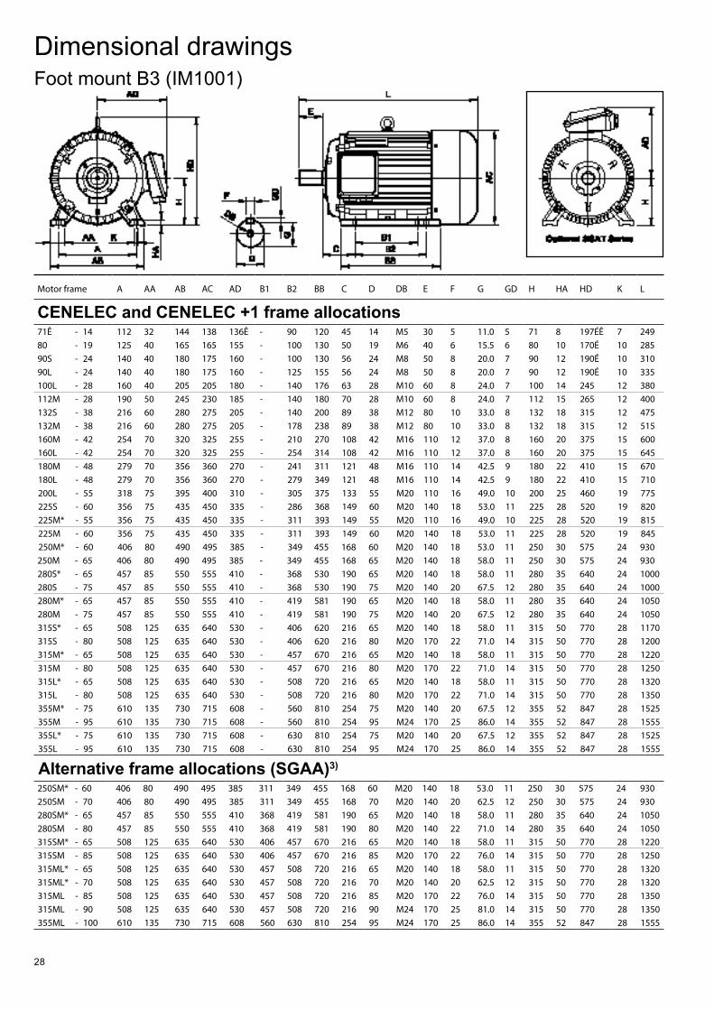
28
Dimensional drawingsFoot mount B3 (IM1001)
Motor frame A AA AB AC AD B1 B2 BB C D DB E F G GD H HA HD K L
CENELEC and CENELEC +1 frame allocations71Ê - 14 112 32 144 138 136Ê - 90 120 45 14 M5 30 5 11.0 5 71 8 197ÉÊ 7 24980 - 19 125 40 165 165 155 - 100 130 50 19 M6 40 6 15.5 6 80 10 170É 10 28590S - 24 140 40 180 175 160 - 100 130 56 24 M8 50 8 20.0 7 90 12 190É 10 31090L - 24 140 40 180 175 160 - 125 155 56 24 M8 50 8 20.0 7 90 12 190É 10 335100L - 28 160 40 205 205 180 - 140 176 63 28 M10 60 8 24.0 7 100 14 245 12 380112M - 28 190 50 245 230 185 - 140 180 70 28 M10 60 8 24.0 7 112 15 265 12 400132S - 38 216 60 280 275 205 - 140 200 89 38 M12 80 10 33.0 8 132 18 315 12 475132M - 38 216 60 280 275 205 - 178 238 89 38 M12 80 10 33.0 8 132 18 315 12 515160M - 42 254 70 320 325 255 - 210 270 108 42 M16 110 12 37.0 8 160 20 375 15 600160L - 42 254 70 320 325 255 - 254 314 108 42 M16 110 12 37.0 8 160 20 375 15 645180M - 48 279 70 356 360 270 - 241 311 121 48 M16 110 14 42.5 9 180 22 410 15 670180L - 48 279 70 356 360 270 - 279 349 121 48 M16 110 14 42.5 9 180 22 410 15 710200L - 55 318 75 395 400 310 - 305 375 133 55 M20 110 16 49.0 10 200 25 460 19 775225S - 60 356 75 435 450 335 - 286 368 149 60 M20 140 18 53.0 11 225 28 520 19 820225M* - 55 356 75 435 450 335 - 311 393 149 55 M20 110 16 49.0 10 225 28 520 19 815225M - 60 356 75 435 450 335 - 311 393 149 60 M20 140 18 53.0 11 225 28 520 19 845250M* - 60 406 80 490 495 385 - 349 455 168 60 M20 140 18 53.0 11 250 30 575 24 930250M - 65 406 80 490 495 385 - 349 455 168 65 M20 140 18 58.0 11 250 30 575 24 930280S* - 65 457 85 550 555 410 - 368 530 190 65 M20 140 18 58.0 11 280 35 640 24 1000280S - 75 457 85 550 555 410 - 368 530 190 75 M20 140 20 67.5 12 280 35 640 24 1000280M* - 65 457 85 550 555 410 - 419 581 190 65 M20 140 18 58.0 11 280 35 640 24 1050280M - 75 457 85 550 555 410 - 419 581 190 75 M20 140 20 67.5 12 280 35 640 24 1050315S* - 65 508 125 635 640 530 - 406 620 216 65 M20 140 18 58.0 11 315 50 770 28 1170315S - 80 508 125 635 640 530 - 406 620 216 80 M20 170 22 71.0 14 315 50 770 28 1200315M* - 65 508 125 635 640 530 - 457 670 216 65 M20 140 18 58.0 11 315 50 770 28 1220315M - 80 508 125 635 640 530 - 457 670 216 80 M20 170 22 71.0 14 315 50 770 28 1250315L* - 65 508 125 635 640 530 - 508 720 216 65 M20 140 18 58.0 11 315 50 770 28 1320315L - 80 508 125 635 640 530 - 508 720 216 80 M20 170 22 71.0 14 315 50 770 28 1350355M* - 75 610 135 730 715 608 - 560 810 254 75 M20 140 20 67.5 12 355 52 847 28 1525355M - 95 610 135 730 715 608 - 560 810 254 95 M24 170 25 86.0 14 355 52 847 28 1555355L* - 75 610 135 730 715 608 - 630 810 254 75 M20 140 20 67.5 12 355 52 847 28 1525355L - 95 610 135 730 715 608 - 630 810 254 95 M24 170 25 86.0 14 355 52 847 28 1555
Alternative frame allocations (SGAA)3)
250SM* - 60 406 80 490 495 385 311 349 455 168 60 M20 140 18 53.0 11 250 30 575 24 930250SM - 70 406 80 490 495 385 311 349 455 168 70 M20 140 20 62.5 12 250 30 575 24 930280SM* - 65 457 85 550 555 410 368 419 581 190 65 M20 140 18 58.0 11 280 35 640 24 1050280SM - 80 457 85 550 555 410 368 419 581 190 80 M20 140 22 71.0 14 280 35 640 24 1050315SM* - 65 508 125 635 640 530 406 457 670 216 65 M20 140 18 58.0 11 315 50 770 28 1220315SM - 85 508 125 635 640 530 406 457 670 216 85 M20 170 22 76.0 14 315 50 770 28 1250315ML* - 65 508 125 635 640 530 457 508 720 216 65 M20 140 18 58.0 11 315 50 770 28 1320315ML* - 70 508 125 635 640 530 457 508 720 216 70 M20 140 20 62.5 12 315 50 770 28 1320315ML - 85 508 125 635 640 530 457 508 720 216 85 M20 170 22 76.0 14 315 50 770 28 1350315ML - 90 508 125 635 640 530 457 508 720 216 90 M24 170 25 81.0 14 315 50 770 28 1350355ML - 100 610 135 730 715 608 560 630 810 254 95 M24 170 25 86.0 14 355 52 847 28 1555
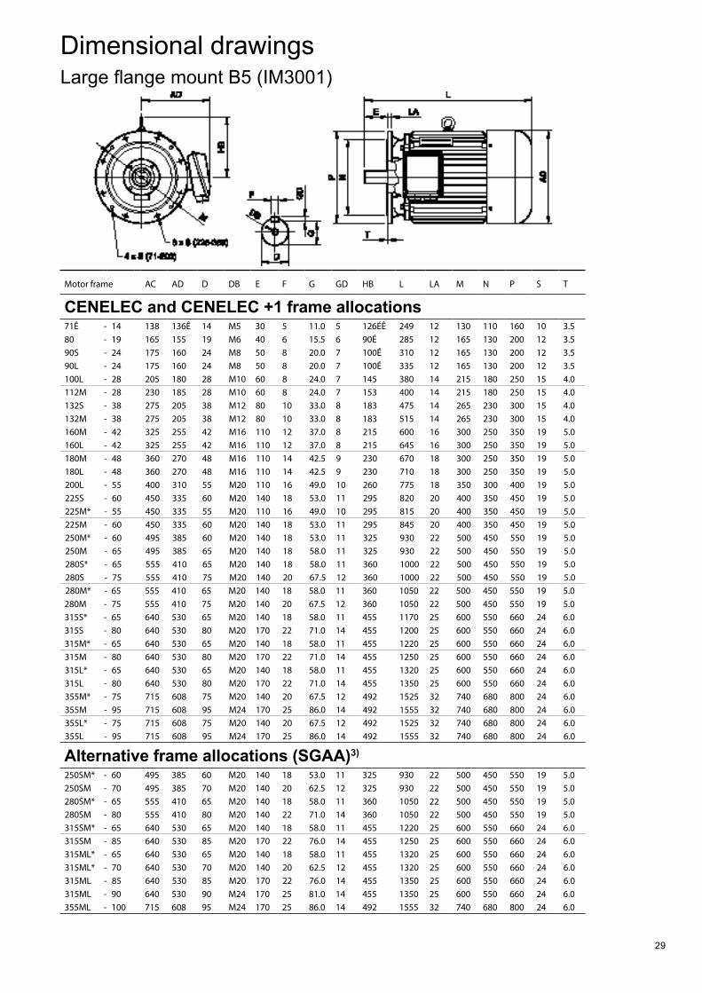
29
Dimensional drawingsLarge flange mount B5 (IM3001)
Motor frame AC AD D DB E F G GD HB L LA M N P S T
CENELEC and CENELEC +1 frame allocations71Ê - 14 138 136Ê 14 M5 30 5 11.0 5 126ÉÊ 249 12 130 110 160 10 3.580 - 19 165 155 19 M6 40 6 15.5 6 90É 285 12 165 130 200 12 3.590S - 24 175 160 24 M8 50 8 20.0 7 100É 310 12 165 130 200 12 3.590L - 24 175 160 24 M8 50 8 20.0 7 100É 335 12 165 130 200 12 3.5100L - 28 205 180 28 M10 60 8 24.0 7 145 380 14 215 180 250 15 4.0112M - 28 230 185 28 M10 60 8 24.0 7 153 400 14 215 180 250 15 4.0132S - 38 275 205 38 M12 80 10 33.0 8 183 475 14 265 230 300 15 4.0132M - 38 275 205 38 M12 80 10 33.0 8 183 515 14 265 230 300 15 4.0160M - 42 325 255 42 M16 110 12 37.0 8 215 600 16 300 250 350 19 5.0160L - 42 325 255 42 M16 110 12 37.0 8 215 645 16 300 250 350 19 5.0180M - 48 360 270 48 M16 110 14 42.5 9 230 670 18 300 250 350 19 5.0180L - 48 360 270 48 M16 110 14 42.5 9 230 710 18 300 250 350 19 5.0200L - 55 400 310 55 M20 110 16 49.0 10 260 775 18 350 300 400 19 5.0225S - 60 450 335 60 M20 140 18 53.0 11 295 820 20 400 350 450 19 5.0225M* - 55 450 335 55 M20 110 16 49.0 10 295 815 20 400 350 450 19 5.0225M - 60 450 335 60 M20 140 18 53.0 11 295 845 20 400 350 450 19 5.0250M* - 60 495 385 60 M20 140 18 53.0 11 325 930 22 500 450 550 19 5.0250M - 65 495 385 65 M20 140 18 58.0 11 325 930 22 500 450 550 19 5.0280S* - 65 555 410 65 M20 140 18 58.0 11 360 1000 22 500 450 550 19 5.0280S - 75 555 410 75 M20 140 20 67.5 12 360 1000 22 500 450 550 19 5.0280M* - 65 555 410 65 M20 140 18 58.0 11 360 1050 22 500 450 550 19 5.0280M - 75 555 410 75 M20 140 20 67.5 12 360 1050 22 500 450 550 19 5.0315S* - 65 640 530 65 M20 140 18 58.0 11 455 1170 25 600 550 660 24 6.0315S - 80 640 530 80 M20 170 22 71.0 14 455 1200 25 600 550 660 24 6.0315M* - 65 640 530 65 M20 140 18 58.0 11 455 1220 25 600 550 660 24 6.0315M - 80 640 530 80 M20 170 22 71.0 14 455 1250 25 600 550 660 24 6.0315L* - 65 640 530 65 M20 140 18 58.0 11 455 1320 25 600 550 660 24 6.0315L - 80 640 530 80 M20 170 22 71.0 14 455 1350 25 600 550 660 24 6.0355M* - 75 715 608 75 M20 140 20 67.5 12 492 1525 32 740 680 800 24 6.0355M - 95 715 608 95 M24 170 25 86.0 14 492 1555 32 740 680 800 24 6.0355L* - 75 715 608 75 M20 140 20 67.5 12 492 1525 32 740 680 800 24 6.0355L - 95 715 608 95 M24 170 25 86.0 14 492 1555 32 740 680 800 24 6.0
Alternative frame allocations (SGAA)3)
250SM* - 60 495 385 60 M20 140 18 53.0 11 325 930 22 500 450 550 19 5.0250SM - 70 495 385 70 M20 140 20 62.5 12 325 930 22 500 450 550 19 5.0280SM* - 65 555 410 65 M20 140 18 58.0 11 360 1050 22 500 450 550 19 5.0280SM - 80 555 410 80 M20 140 22 71.0 14 360 1050 22 500 450 550 19 5.0315SM* - 65 640 530 65 M20 140 18 58.0 11 455 1220 25 600 550 660 24 6.0315SM - 85 640 530 85 M20 170 22 76.0 14 455 1250 25 600 550 660 24 6.0315ML* - 65 640 530 65 M20 140 18 58.0 11 455 1320 25 600 550 660 24 6.0315ML* - 70 640 530 70 M20 140 20 62.5 12 455 1320 25 600 550 660 24 6.0315ML - 85 640 530 85 M20 170 22 76.0 14 455 1350 25 600 550 660 24 6.0315ML - 90 640 530 90 M24 170 25 81.0 14 455 1350 25 600 550 660 24 6.0355ML - 100 715 608 95 M24 170 25 86.0 14 492 1555 32 740 680 800 24 6.0
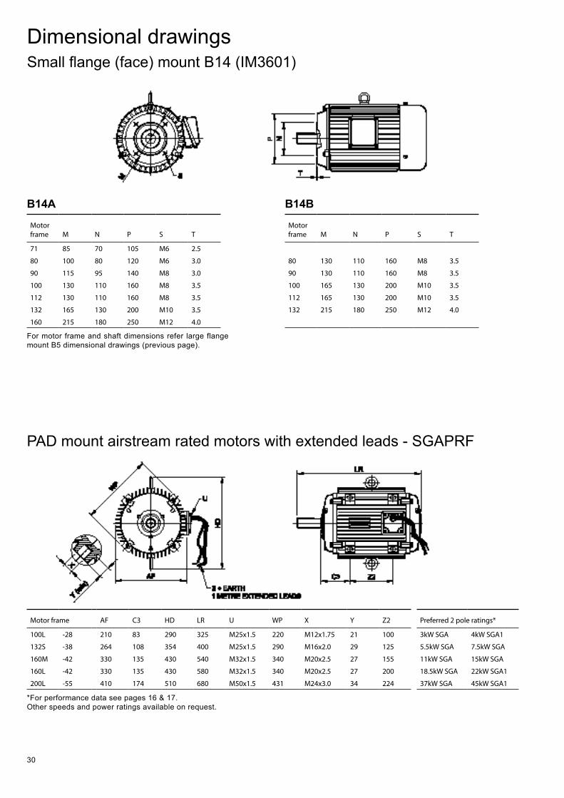
30
Dimensional drawingsSmall flange (face) mount B14 (IM3601)
Motor frame M N P S T
71 85 70 105 M6 2.5
80 100 80 120 M6 3.0
90 115 95 140 M8 3.0
100 130 110 160 M8 3.5
112 130 110 160 M8 3.5
132 165 130 200 M10 3.5
160 215 180 250 M12 4.0
Motor frame M N P S T
80 130 110 160 M8 3.5
90 130 110 160 M8 3.5
100 165 130 200 M10 3.5
112 165 130 200 M10 3.5
132 215 180 250 M12 4.0
For motor frame and shaft dimensions refer large flange mount B5 dimensional drawings (previous page).
*For performance data see pages 16 & 17.Other speeds and power ratings available on request.
PAD mount airstream rated motors with extended leads - SGAPRF
Motor frame AF C3 HD LR U WP X Y Z2 Preferred 2 pole ratings*
100L -28 210 83 290 325 M25x1.5 220 M12x1.75 21 100 3kW SGA 4kW SGA1
132S -38 264 108 354 400 M25x1.5 290 M16x2.0 29 125 5.5kW SGA 7.5kW SGA
160M -42 330 135 430 540 M32x1.5 340 M20x2.5 27 155 11kW SGA 15kW SGA
160L -42 330 135 430 580 M32x1.5 340 M20x2.5 27 200 18.5kW SGA 22kW SGA1
200L -55 410 174 510 680 M50x1.5 431 M24x3.0 34 224 37kW SGA 45kW SGA1
B14A B14B
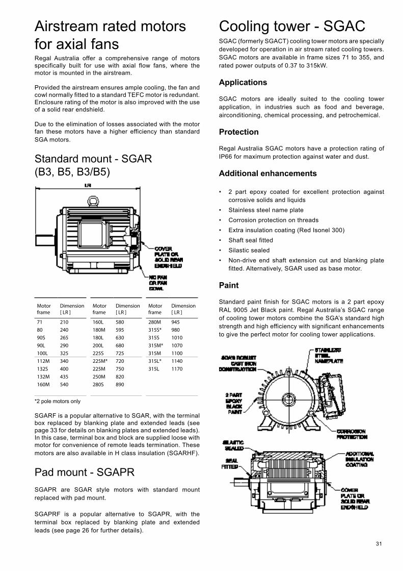
31
Airstream rated motors for axial fans Regal Australia offer a comprehensive range of motors specifically built for use with axial flow fans, where the motor is mounted in the airstream.
Provided the airstream ensures ample cooling, the fan and cowl normally fitted to a standard TEFC motor is redundant. Enclosure rating of the motor is also improved with the use of a solid rear endshield.
Due to the elimination of losses associated with the motor fan these motors have a higher efficiency than standard SGA motors.
Standard mount - SGAR (B3, B5, B3/B5)
Motor frame
Dimension [ LR ]
Motor frame
Dimension [ LR ]
Motor frame
Dimension [ LR ]
71 210 160L 580 280M 94580 240 180M 595 315S* 98090S 265 180L 630 315S 101090L 290 200L 680 315M* 1070100L 325 225S 725 315M 1100112M 340 225M* 720 315L* 1140132S 400 225M 750 315L 1170132M 435 250M 820160M 540 280S 890
*2 pole motors only
SGARF is a popular alternative to SGAR, with the terminal box replaced by blanking plate and extended leads (see page 33 for details on blanking plates and extended leads). In this case, terminal box and block are supplied loose with motor for convenience of remote leads termination. These motors are also available in H class insulation (SGARHF).
Pad mount - SGAPRSGAPR are SGAR style motors with standard mount replaced with pad mount.
SGAPRF is a popular alternative to SGAPR, with the terminal box replaced by blanking plate and extended leads (see page 26 for further details).
Cooling tower - SGAC SGAC (formerly SGACT) cooling tower motors are specially developed for operation in air stream rated cooling towers. SGAC motors are available in frame sizes 71 to 355, and rated power outputs of 0.37 to 315kW.
Applications
SGAC motors are ideally suited to the cooling tower application, in industries such as food and beverage, airconditioning, chemical processing, and petrochemical.
Protection
Regal Australia SGAC motors have a protection rating of IP66 for maximum protection against water and dust.
Additional enhancements
• 2 part epoxy coated for excellent protection against corrosive solids and liquids
• Stainless steel name plate • Corrosion protection on threads • Extra insulation coating (Red Isonel 300) • Shaft seal fitted • Silastic sealed • Non-drive end shaft extension cut and blanking plate
fitted. Alternatively, SGAR used as base motor.
Paint
Standard paint finish for SGAC motors is a 2 part epoxy RAL 9005 Jet Black paint. Regal Australia’s SGAC range of cooling tower motors combine the SGA’s standard high strength and high efficiency with significant enhancements to give the perfect motor for cooling tower applications.
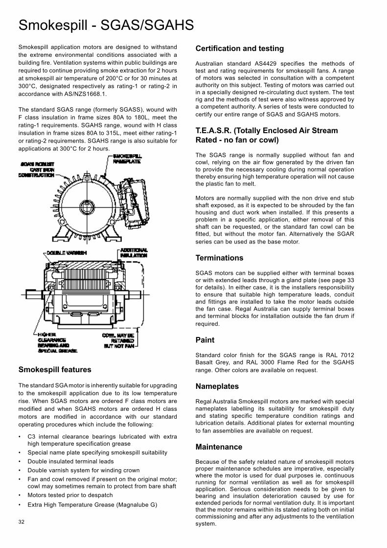
32
Smokespill application motors are designed to withstand the extreme environmental conditions associated with a building fire. Ventilation systems within public buildings are required to continue providing smoke extraction for 2 hours at smokespill air temperature of 200°C or for 30 minutes at 300°C, designated respectively as rating-1 or rating-2 in accordance with AS/NZS1668.1.
The standard SGAS range (formerly SGASS), wound with F class insulation in frame sizes 80A to 180L, meet the rating-1 requirements. SGAHS range, wound with H class insulation in frame sizes 80A to 315L, meet either rating-1 or rating-2 requirements. SGAHS range is also suitable for applications at 300°C for 2 hours.
Smokespill features
The standard SGA motor is inherently suitable for upgrading to the smokespill application due to its low temperature rise. When SGAS motors are ordered F class motors are modified and when SGAHS motors are ordered H class motors are modified in accordance with our standard operating procedures which include the following:
• C3 internal clearance bearings lubricated with extra high temperature specification grease
• Special name plate specifying smokespill suitability • Double insulated terminal leads • Double varnish system for winding crown • Fan and cowl removed if present on the original motor;
cowl may sometimes remain to protect from bare shaft • Motors tested prior to despatch • Extra High Temperature Grease (Magnalube G)
Certification and testing
Australian standard AS4429 specifies the methods of test and rating requirements for smokespill fans. A range of motors was selected in consultation with a competent authority on this subject. Testing of motors was carried out in a specially designed re-circulating duct system. The test rig and the methods of test were also witness approved by a competent authority. A series of tests were conducted to certify our entire range of SGAS and SGAHS motors.
T.E.A.S.R. (Totally Enclosed Air Stream Rated - no fan or cowl)
The SGAS range is normally supplied without fan and cowl, relying on the air flow generated by the driven fan to provide the necessary cooling during normal operation thereby ensuring high temperature operation will not cause the plastic fan to melt.
Motors are normally supplied with the non drive end stub shaft exposed, as it is expected to be shrouded by the fan housing and duct work when installed. If this presents a problem in a specific application, either removal of this shaft can be requested, or the standard fan cowl can be fitted, but without the motor fan. Alternatively the SGAR series can be used as the base motor.
Terminations
SGAS motors can be supplied either with terminal boxes or with extended leads through a gland plate (see page 33 for details). In either case, it is the installers responsibility to ensure that suitable high temperature leads, conduit and fittings are installed to take the motor leads outside the fan case. Regal Australia can supply terminal boxes and terminal blocks for installation outside the fan drum if required.
Paint
Standard color finish for the SGAS range is RAL 7012 Basalt Grey, and RAL 3000 Flame Red for the SGAHS range. Other colors are available on request.
Nameplates
Regal Australia Smokespill motors are marked with special nameplates labelling its suitability for smokespill duty and stating specific temperature condition ratings and lubrication details. Additional plates for external mounting to fan assemblies are available on request.
Maintenance
Because of the safety related nature of smokespill motors proper maintenance schedules are imperative, especially where the motor is used for dual purposes ie. continuous running for normal ventilation as well as for smokespill application. Serious consideration needs to be given to bearing and insulation deterioration caused by use for extended periods for normal ventilation duty. It is important that the motor remains within its stated rating both on initial commissioning and after any adjustments to the ventilation system.
Smokespill - SGAS/SGAHS
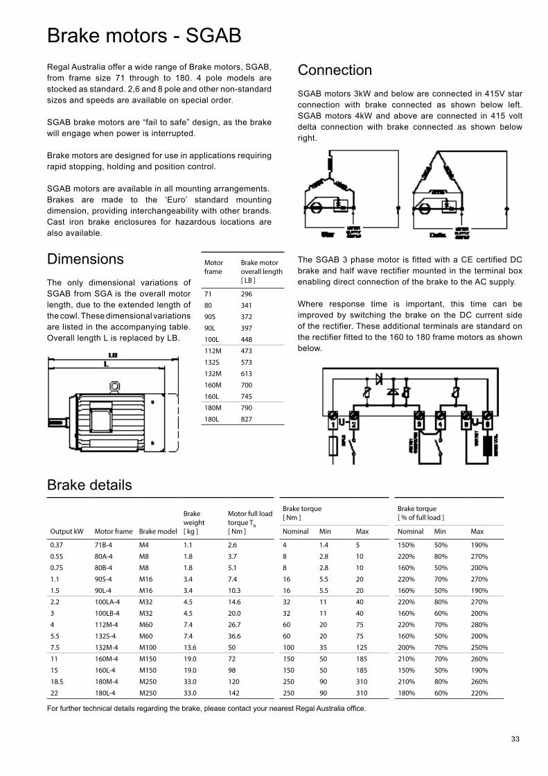
33
Brake motors - SGAB Regal Australia offer a wide range of Brake motors, SGAB, from frame size 71 through to 180. 4 pole models are stocked as standard. 2,6 and 8 pole and other non-standard sizes and speeds are available on special order.
SGAB brake motors are “fail to safe” design, as the brake will engage when power is interrupted.
Brake motors are designed for use in applications requiring rapid stopping, holding and position control.
SGAB motors are available in all mounting arrangements. Brakes are made to the ‘Euro’ standard mounting dimension, providing interchangeability with other brands. Cast iron brake enclosures for hazardous locations are also available.
Dimensions The only dimensional variations of SGAB from SGA is the overall motor length, due to the extended length of the cowl. These dimensional variations are listed in the accompanying table. Overall length L is replaced by LB.
Connection SGAB motors 3kW and below are connected in 415V star connection with brake connected as shown below left. SGAB motors 4kW and above are connected in 415 volt delta connection with brake connected as shown below right.
The SGAB 3 phase motor is fitted with a CE certified DC brake and half wave rectifier mounted in the terminal box enabling direct connection of the brake to the AC supply.
Where response time is important, this time can be improved by switching the brake on the DC current side of the rectifier. These additional terminals are standard on the rectifier fitted to the 160 to 180 frame motors as shown below.
Motor frame
Brake motor overall length [ LB ]
71 296
80 341
90S 372
90L 397
100L 448
112M 473
132S 573
132M 613
160M 700
160L 745
180M 790
180L 827
Output kW Motor frame Brake model
Brake weight [ kg ]
Motor full load torque TN [ Nm ]
Brake torque [ Nm ]
Brake torque [ % of full load ]
Nominal Min Max Nominal Min Max
0.37 71B-4 M4 1.1 2.6 4 1.4 5 150% 50% 190%
0.55 80A-4 M8 1.8 3.7 8 2.8 10 220% 80% 270%
0.75 80B-4 M8 1.8 5.1 8 2.8 10 160% 50% 200%
1.1 90S-4 M16 3.4 7.4 16 5.5 20 220% 70% 270%
1.5 90L-4 M16 3.4 10.3 16 5.5 20 160% 50% 190%
2.2 100LA-4 M32 4.5 14.6 32 11 40 220% 80% 270%
3 100LB-4 M32 4.5 20.0 32 11 40 160% 60% 200%
4 112M-4 M60 7.4 26.7 60 20 75 220% 70% 280%
5.5 132S-4 M60 7.4 36.6 60 20 75 160% 50% 200%
7.5 132M-4 M100 13.6 50 100 35 125 200% 70% 250%
11 160M-4 M150 19.0 72 150 50 185 210% 70% 260%
15 160L-4 M150 19.0 98 150 50 185 150% 50% 190%
18.5 180M-4 M250 33.0 120 250 90 310 210% 80% 260%
22 180L-4 M250 33.0 142 250 90 310 180% 60% 220%
Brake details
For further technical details regarding the brake, please contact your nearest Regal Australia office.
34
SGAE/SGAN/SGAD
Motors used within a hazardous location require a higher level of protection against the risk of harmful occurrences. Regal Australia SGA motors are available in the three most common high protection configurations, Ex e, Ex nA (formerly Ex n) and Ex tD (formerly DIP), supplied with protection ratings IP55, IP65 or IP66. SGA Hazardous area motors are available in motor frame sizes 71 to 280, with 315 frame certificate pending (Ex nA and Ex tD only). Combinations of protection such as Ex e and Ex tD or Ex nA and Ex tD are also available.
International and Australian standards
IEC or AS/NZS 61241.1 and AS 2381.1 specify general requirements for the selection of electrical equipment, and its installation and maintenance to ensure safe use in areas where flammable materials are generated, prepared, processed, handled, stored or otherwise used, and which are therefore potentially hazardous.
The term ‘flammable material’ includes gases, vapors, liquids, mists, solids and dusts, but does not include those materials which are specifically manufactured as explosives or materials which are inherently explosive. The requirements of the listed standards apply only to the use of electrical equipment under normal or near normal atmospheric conditions.
The requirements specified for hazardous location electrical equipment are supplementary to and not alternative to any requirements which would apply to equipment and installations in non-hazardous areas (see AS/NZS3000).
European Standards
European standards ‘EN’ series are closely aligned with IEC standards. They share the same numbering and require assessment and certification to ATEX directives, issued by the European Union.
The ATEX directive (94/9/EC, 23.03.94) addresses both the compliance of hazardous area equipment to specified standards, and the compliance to EH&SR (Essential Health & Safety Requirements).
Paint
Standard color finish for the hazardous area range is RAL 7012 Basalt Grey, with primary option of RAL 1004 Golden Yellow for SGAE. Other colors are available on request.
Motor protection types
SGAE - Ex e
Ex e motor protection designates Increased safety as outlined in IEC, EN or AS/NZS 60079-7.
The increased safety (Ex e) type of protection describes electrical equipment that does not produce arcs or sparks in normal service in which additional measures are applied so as to give increased security against the possibility of excessive temperatures and of the occurrence of arcs and sparks.
Increased safety (Ex e) motors are suitable for Class I, Zone 1, Group II (A,B&C) hazardous areas, and Regal Australia provides for a temperature class of T3 (200°C) in a 40°C ambient (see next page for explanations of classes, zones and groups).
Ex e Protection - tE time tE time is the time it takes for the stator winding or rotor cage to heat up from normal operating temperature, at the highest permitted ambient temperature, to the highest permitted limit temperature (temperature class), with the rotor locked and the stator winding loaded with the starting current.
For selection and setting of suitable current dependent protection the tE time and the ratio of locked rotor current to nominal current are used. In the case of a rotor locking, this device must cut off the supply within the specified tE time, which is listed in the performance data.
SGAN - Ex nA (formerly Ex n)
Ex nA motor protection designates Non-sparking as outlined in IEC, EN or AS/NZS 60079-15. Non-sparking (Ex nA) type of protection describes electrical equipment that, in normal operation, is not capable of igniting a surrounding explosive atmosphere, and a fault capable of causing ignition is not likely to occur.
Non-sparking (Ex nA) motors are suitable for Class I, Zone 2, Group II (A,B&C) hazardous areas, and Regal Australia provides for a temperature class of T3 (200°C) in a 50°C ambient.
Motors for hazardous areas
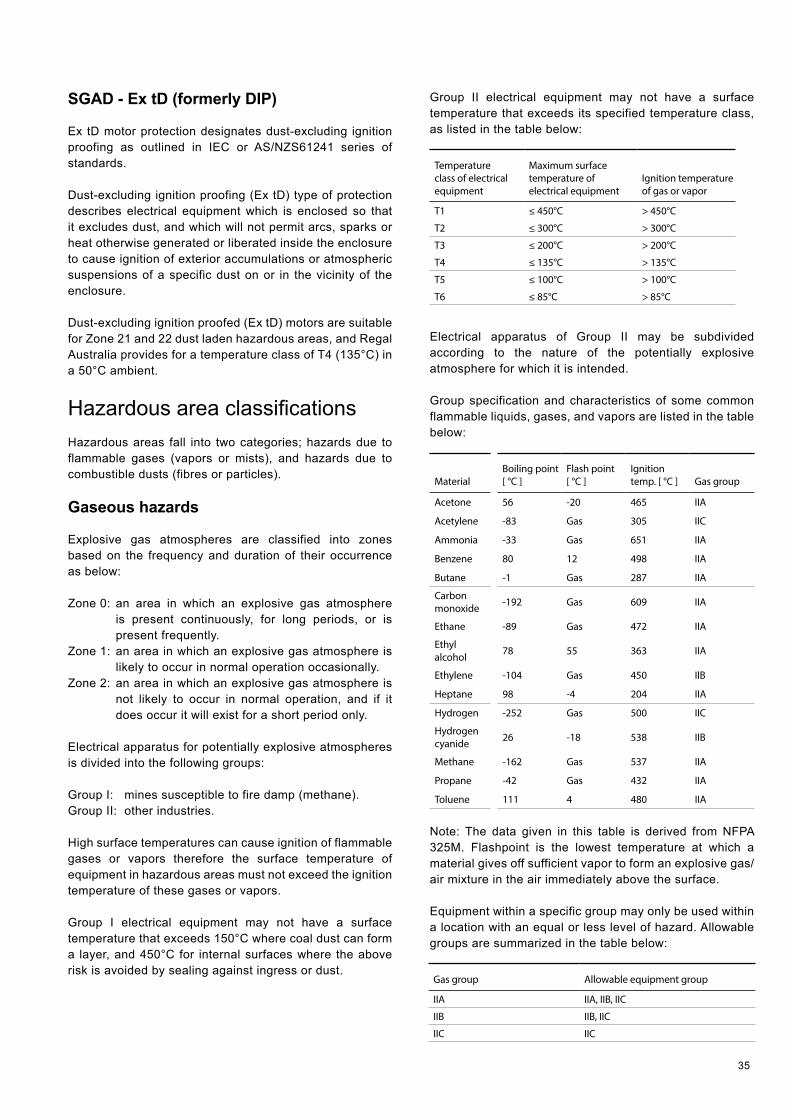
35
SGAD - Ex tD (formerly DIP)
Ex tD motor protection designates dust-excluding ignition proofing as outlined in IEC or AS/NZS61241 series of standards.
Dust-excluding ignition proofing (Ex tD) type of protection describes electrical equipment which is enclosed so that it excludes dust, and which will not permit arcs, sparks or heat otherwise generated or liberated inside the enclosure to cause ignition of exterior accumulations or atmospheric suspensions of a specific dust on or in the vicinity of the enclosure.
Dust-excluding ignition proofed (Ex tD) motors are suitable for Zone 21 and 22 dust laden hazardous areas, and Regal Australia provides for a temperature class of T4 (135°C) in a 50°C ambient.
Hazardous area classifications Hazardous areas fall into two categories; hazards due to flammable gases (vapors or mists), and hazards due to combustible dusts (fibres or particles).
Gaseous hazards
Explosive gas atmospheres are classified into zones based on the frequency and duration of their occurrence as below:
Zone 0: an area in which an explosive gas atmosphere is present continuously, for long periods, or is present frequently.
Zone 1: an area in which an explosive gas atmosphere is likely to occur in normal operation occasionally.
Zone 2: an area in which an explosive gas atmosphere is not likely to occur in normal operation, and if it does occur it will exist for a short period only.
Electrical apparatus for potentially explosive atmospheres is divided into the following groups:
Group I: mines susceptible to fire damp (methane).Group II: other industries.
High surface temperatures can cause ignition of flammable gases or vapors therefore the surface temperature of equipment in hazardous areas must not exceed the ignition temperature of these gases or vapors.
Group I electrical equipment may not have a surface temperature that exceeds 150°C where coal dust can form a layer, and 450°C for internal surfaces where the above risk is avoided by sealing against ingress or dust.
Group II electrical equipment may not have a surface temperature that exceeds its specified temperature class, as listed in the table below:
Temperature class of electrical equipment
Maximum surface temperature of electrical equipment
Ignition temperature of gas or vapor
T1 ≤ 450°C > 450°C
T2 ≤ 300°C > 300°C
T3 ≤ 200°C > 200°C
T4 ≤ 135°C > 135°C
T5 ≤ 100°C > 100°C
T6 ≤ 85°C > 85°C
Electrical apparatus of Group II may be subdivided according to the nature of the potentially explosive atmosphere for which it is intended.
Group specification and characteristics of some common flammable liquids, gases, and vapors are listed in the table below:
MaterialBoiling point [ °C ]
Flash point [ °C ]
Ignition temp. [ °C ] Gas group
Acetone 56 -20 465 IIA
Acetylene -83 Gas 305 IIC
Ammonia -33 Gas 651 IIA
Benzene 80 12 498 IIA
Butane -1 Gas 287 IIA
Carbon monoxide -192 Gas 609 IIA
Ethane -89 Gas 472 IIA
Ethyl alcohol 78 55 363 IIA
Ethylene -104 Gas 450 IIB
Heptane 98 -4 204 IIA
Hydrogen -252 Gas 500 IIC
Hydrogen cyanide 26 -18 538 IIB
Methane -162 Gas 537 IIA
Propane -42 Gas 432 IIA
Toluene 111 4 480 IIA
Note: The data given in this table is derived from NFPA 325M. Flashpoint is the lowest temperature at which a material gives off sufficient vapor to form an explosive gas/air mixture in the air immediately above the surface.
Equipment within a specific group may only be used within a location with an equal or less level of hazard. Allowable groups are summarized in the table below:
Gas group Allowable equipment group
IIA IIA, IIB, IIC
IIB IIB, IIC
IIC IIC
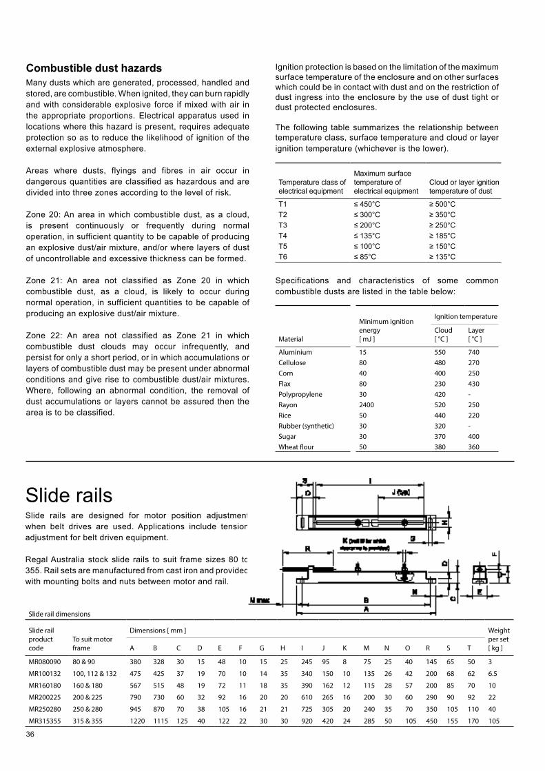
36
Combustible dust hazardsMany dusts which are generated, processed, handled and stored, are combustible. When ignited, they can burn rapidly and with considerable explosive force if mixed with air in the appropriate proportions. Electrical apparatus used in locations where this hazard is present, requires adequate protection so as to reduce the likelihood of ignition of the external explosive atmosphere.
Areas where dusts, flyings and fibres in air occur in dangerous quantities are classified as hazardous and are divided into three zones according to the level of risk.
Zone 20: An area in which combustible dust, as a cloud, is present continuously or frequently during normal operation, in sufficient quantity to be capable of producing an explosive dust/air mixture, and/or where layers of dust of uncontrollable and excessive thickness can be formed.
Zone 21: An area not classified as Zone 20 in which combustible dust, as a cloud, is likely to occur during normal operation, in sufficient quantities to be capable of producing an explosive dust/air mixture.
Zone 22: An area not classified as Zone 21 in which combustible dust clouds may occur infrequently, and persist for only a short period, or in which accumulations or layers of combustible dust may be present under abnormal conditions and give rise to combustible dust/air mixtures. Where, following an abnormal condition, the removal of dust accumulations or layers cannot be assured then the area is to be classified.
Ignition protection is based on the limitation of the maximum surface temperature of the enclosure and on other surfaces which could be in contact with dust and on the restriction of dust ingress into the enclosure by the use of dust tight or dust protected enclosures.
The following table summarizes the relationship between temperature class, surface temperature and cloud or layer ignition temperature (whichever is the lower).
Temperature class of electrical equipment
Maximum surface temperature of electrical equipment
Cloud or layer ignition temperature of dust
T1 ≤ 450°C ≥ 500°CT2 ≤ 300°C ≥ 350°CT3 ≤ 200°C ≥ 250°CT4 ≤ 135°C ≥ 185°CT5 ≤ 100°C ≥ 150°CT6 ≤ 85°C ≥ 135°C
Specifications and characteristics of some common combustible dusts are listed in the table below:
Material
Minimum ignition energy [ mJ ]
Ignition temperature
Cloud [ °C ]
Layer [ °C ]
Aluminium 15 550 740Cellulose 80 480 270Corn 40 400 250Flax 80 230 430Polypropylene 30 420 -Rayon 2400 520 250Rice 50 440 220Rubber (synthetic) 30 320 -Sugar 30 370 400Wheat flour 50 380 360
Slide railsSlide rails are designed for motor position adjustment when belt drives are used. Applications include tension adjustment for belt driven equipment.
Regal Australia stock slide rails to suit frame sizes 80 to 355. Rail sets are manufactured from cast iron and provided with mounting bolts and nuts between motor and rail.
Slide rail dimensions
Slide rail product code
To suit motor frame
Dimensions [ mm ] Weight per set [ kg ]A B C D E F G H I J K M N O R S T
MR080090 80 & 90 380 328 30 15 48 10 15 25 245 95 8 75 25 40 145 65 50 3
MR100132 100, 112 & 132 475 425 37 19 70 10 14 35 340 150 10 135 26 42 200 68 62 6.5
MR160180 160 & 180 567 515 48 19 72 11 18 35 390 162 12 115 28 57 200 85 70 10
MR200225 200 & 225 790 730 60 32 92 16 20 20 610 265 16 200 30 60 290 90 92 22
MR250280 250 & 280 945 870 70 38 105 16 21 21 725 305 20 240 35 70 350 105 110 40
MR315355 315 & 355 1220 1115 125 40 122 22 30 30 920 420 24 285 50 105 450 155 170 105
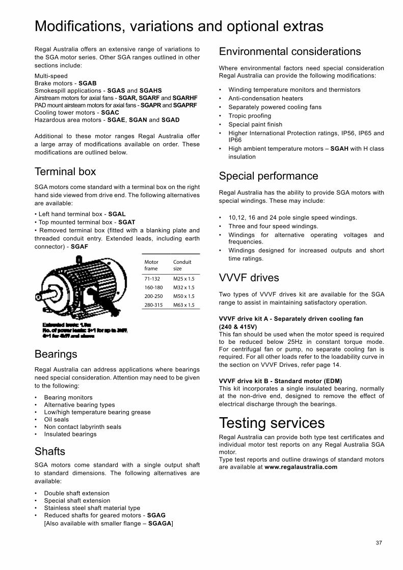
37
Regal Australia offers an extensive range of variations to the SGA motor series. Other SGA ranges outlined in other sections include:
Multi-speed Brake motors - SGAB Smokespill applications - SGAS and SGAHS Airstream motors for axial fans - SGAR, SGARF and SGARHF PAD mount airsteam motors for axial fans - SGAPR and SGAPRFCooling tower motors - SGACHazardous area motors - SGAE, SGAN and SGAD
Additional to these motor ranges Regal Australia offer a large array of modifications available on order. These modifications are outlined below.
Terminal box SGA motors come standard with a terminal box on the right hand side viewed from drive end. The following alternatives are available:
• Left hand terminal box - SGAL • Top mounted terminal box - SGAT • Removed terminal box (fitted with a blanking plate and threaded conduit entry. Extended leads, including earth connector) - SGAF
Motor frame
Conduit size
71-132 M25 x 1.5
160-180 M32 x 1.5
200-250 M50 x 1.5
280-315 M63 x 1.5
Bearings Regal Australia can address applications where bearings need special consideration. Attention may need to be given to the following:
• Bearing monitors • Alternative bearing types • Low/high temperature bearing grease • Oil seals • Non contact labyrinth seals • Insulated bearings
Shafts SGA motors come standard with a single output shaft to standard dimensions. The following alternatives are available:
• Double shaft extension • Special shaft extension • Stainless steel shaft material type • Reduced shafts for geared motors - SGAG
[Also available with smaller flange – SGAGA]
Environmental considerations Where environmental factors need special consideration Regal Australia can provide the following modifications:
• Winding temperature monitors and thermistors • Anti-condensation heaters • Separately powered cooling fans • Tropic proofing • Special paint finish • Higher International Protection ratings, IP56, IP65 and
IP66 • High ambient temperature motors – SGAH with H class
insulation
Special performance Regal Australia has the ability to provide SGA motors with special windings. These may include:
• 10,12, 16 and 24 pole single speed windings. • Three and four speed windings. • Windings for alternative operating voltages and
frequencies. • Windings designed for increased outputs and short
time ratings.
VVVF drivesTwo types of VVVF drives kit are available for the SGA range to assist in maintaining satisfactory operation.
VVVF drive kit A - Separately driven cooling fan (240 & 415V)This fan should be used when the motor speed is required to be reduced below 25Hz in constant torque mode. For centrifugal fan or pump, no separate cooling fan is required. For all other loads refer to the loadability curve in the section on VVVF Drives, refer page 14.
VVVF drive kit B - Standard motor (EDM)This kit incorporates a single insulated bearing, normally at the non-drive end, designed to remove the effect of electrical discharge through the bearings.
Testing services Regal Australia can provide both type test certificates and individual motor test reports on any Regal Australia SGA motor.Type test reports and outline drawings of standard motors are available at www.regalaustralia.com
Modifications, variations and optional extras
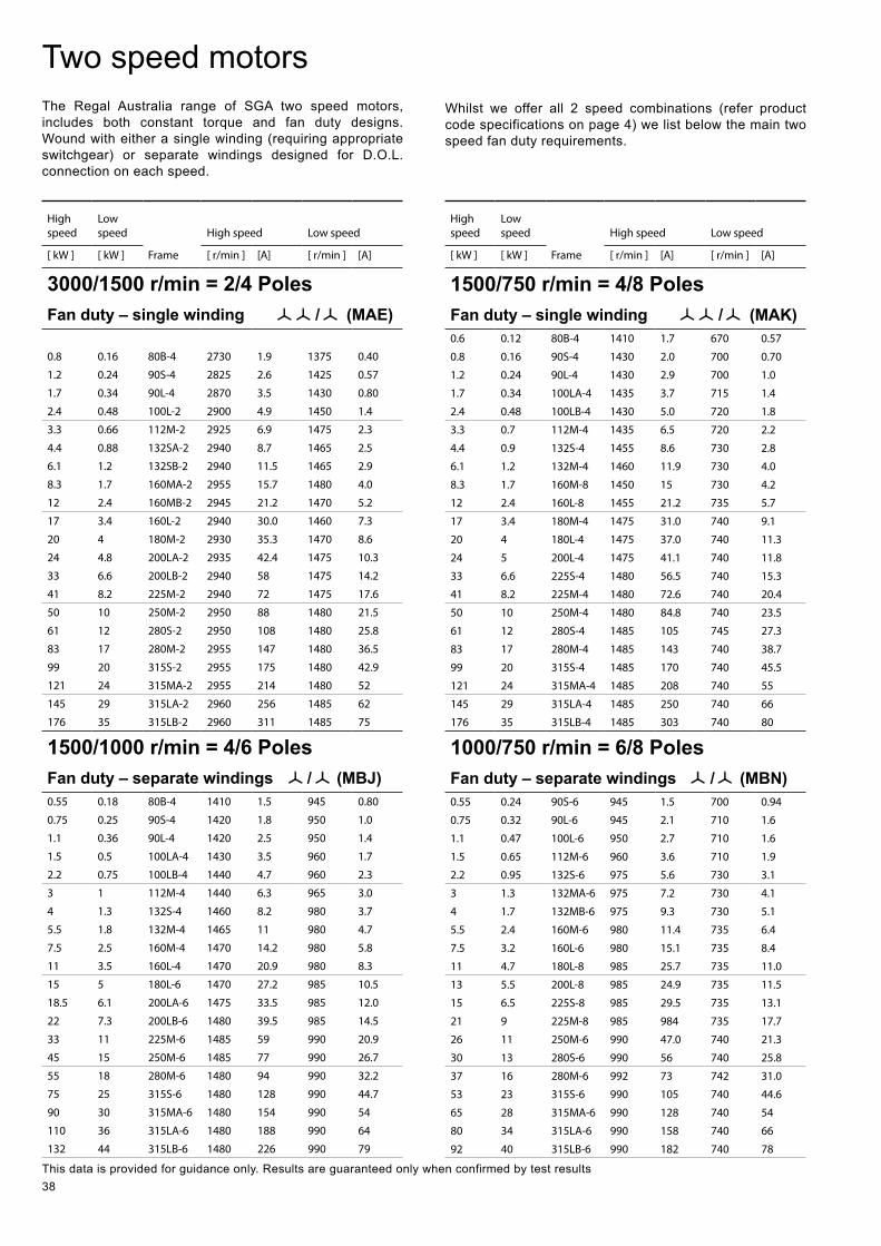
38
Two speed motors The Regal Australia range of SGA two speed motors, includes both constant torque and fan duty designs. Wound with either a single winding (requiring appropriate switchgear) or separate windings designed for D.O.L. connection on each speed.
Whilst we offer all 2 speed combinations (refer product code specifications on page 4) we list below the main two speed fan duty requirements.
This data is provided for guidance only. Results are guaranteed only when confirmed by test results
High speed
Low speed
Frame
High speed Low speed
[ kW ] [ kW ] [ r/min ] [A] [ r/min ] [A]
3000/1500 r/min = 2/4 PolesFan duty – single winding / (MAE)
0.8 0.16 80B-4 2730 1.9 1375 0.40
1.2 0.24 90S-4 2825 2.6 1425 0.57
1.7 0.34 90L-4 2870 3.5 1430 0.80
2.4 0.48 100L-2 2900 4.9 1450 1.4
3.3 0.66 112M-2 2925 6.9 1475 2.3
4.4 0.88 132SA-2 2940 8.7 1465 2.5
6.1 1.2 132SB-2 2940 11.5 1465 2.9
8.3 1.7 160MA-2 2955 15.7 1480 4.0
12 2.4 160MB-2 2945 21.2 1470 5.2
17 3.4 160L-2 2940 30.0 1460 7.3
20 4 180M-2 2930 35.3 1470 8.6
24 4.8 200LA-2 2935 42.4 1475 10.3
33 6.6 200LB-2 2940 58 1475 14.2
41 8.2 225M-2 2940 72 1475 17.6
50 10 250M-2 2950 88 1480 21.5
61 12 280S-2 2950 108 1480 25.8
83 17 280M-2 2955 147 1480 36.5
99 20 315S-2 2955 175 1480 42.9
121 24 315MA-2 2955 214 1480 52
145 29 315LA-2 2960 256 1485 62
176 35 315LB-2 2960 311 1485 75
1500/1000 r/min = 4/6 PolesFan duty – separate windings / (MBJ)0.55 0.18 80B-4 1410 1.5 945 0.80
0.75 0.25 90S-4 1420 1.8 950 1.0
1.1 0.36 90L-4 1420 2.5 950 1.4
1.5 0.5 100LA-4 1430 3.5 960 1.7
2.2 0.75 100LB-4 1440 4.7 960 2.3
3 1 112M-4 1440 6.3 965 3.0
4 1.3 132S-4 1460 8.2 980 3.7
5.5 1.8 132M-4 1465 11 980 4.7
7.5 2.5 160M-4 1470 14.2 980 5.8
11 3.5 160L-4 1470 20.9 980 8.3
15 5 180L-6 1470 27.2 985 10.5
18.5 6.1 200LA-6 1475 33.5 985 12.0
22 7.3 200LB-6 1480 39.5 985 14.5
33 11 225M-6 1485 59 990 20.9
45 15 250M-6 1485 77 990 26.7
55 18 280M-6 1480 94 990 32.2
75 25 315S-6 1480 128 990 44.7
90 30 315MA-6 1480 154 990 54
110 36 315LA-6 1480 188 990 64
132 44 315LB-6 1480 226 990 79
High speed
Low speed
Frame
High speed Low speed
[ kW ] [ kW ] [ r/min ] [A] [ r/min ] [A]
1500/750 r/min = 4/8 PolesFan duty – single winding / (MAK)0.6 0.12 80B-4 1410 1.7 670 0.57
0.8 0.16 90S-4 1430 2.0 700 0.70
1.2 0.24 90L-4 1430 2.9 700 1.0
1.7 0.34 100LA-4 1435 3.7 715 1.4
2.4 0.48 100LB-4 1430 5.0 720 1.8
3.3 0.7 112M-4 1435 6.5 720 2.2
4.4 0.9 132S-4 1455 8.6 730 2.8
6.1 1.2 132M-4 1460 11.9 730 4.0
8.3 1.7 160M-8 1450 15 730 4.2
12 2.4 160L-8 1455 21.2 735 5.7
17 3.4 180M-4 1475 31.0 740 9.1
20 4 180L-4 1475 37.0 740 11.3
24 5 200L-4 1475 41.1 740 11.8
33 6.6 225S-4 1480 56.5 740 15.3
41 8.2 225M-4 1480 72.6 740 20.4
50 10 250M-4 1480 84.8 740 23.5
61 12 280S-4 1485 105 745 27.3
83 17 280M-4 1485 143 740 38.7
99 20 315S-4 1485 170 740 45.5
121 24 315MA-4 1485 208 740 55
145 29 315LA-4 1485 250 740 66
176 35 315LB-4 1485 303 740 80
1000/750 r/min = 6/8 PolesFan duty – separate windings / (MBN)0.55 0.24 90S-6 945 1.5 700 0.94
0.75 0.32 90L-6 945 2.1 710 1.6
1.1 0.47 100L-6 950 2.7 710 1.6
1.5 0.65 112M-6 960 3.6 710 1.9
2.2 0.95 132S-6 975 5.6 730 3.1
3 1.3 132MA-6 975 7.2 730 4.1
4 1.7 132MB-6 975 9.3 730 5.1
5.5 2.4 160M-6 980 11.4 735 6.4
7.5 3.2 160L-6 980 15.1 735 8.4
11 4.7 180L-8 985 25.7 735 11.0
13 5.5 200L-8 985 24.9 735 11.5
15 6.5 225S-8 985 29.5 735 13.1
21 9 225M-8 985 984 735 17.7
26 11 250M-6 990 47.0 740 21.3
30 13 280S-6 990 56 740 25.8
37 16 280M-6 992 73 742 31.0
53 23 315S-6 990 105 740 44.6
65 28 315MA-6 990 128 740 54
80 34 315LA-6 990 158 740 66
92 40 315LB-6 990 182 740 78

39
© Regal Beloit Australia Pty Ltd All information supplied in this publication is accurante at time of printing. Subject to change at any time without prior notice.
MALAYSIATorin Industries SND BHD (MALAYSIA) No. 6536A Jalan Bukit KemuningBatu 6 Seksyen 3440470 Shah Alam SelangorT: +60 3 5124 6157F: +60 3 5121 1467
SINGAPORECMG Electric Motors (Asia Paci� c) Pte Ltd12 Tuas Loop 637346SINGAPORET: +65 6863 3473F: +65 6863 3476
THAILANDFASCO Motors (Thailand) Limited29/7-8 Bangkruay-Sainoi RoadBangkrangMuang Nonthaburi District Nonthaburi 11000THAILANDT: +66 2447 3300F: +66 2447 3500
Regal Beloit Australia Pty Ltd ABN 61 122 303 08419 Corporate Ave (PO Box 2340), Rowville VIC 3178, AUSTRALIAT: +61 3 9237 4000 F: +61 3 9237 4010
Sales Support 1300 888 853 Technical Support 1800 676 722www.regalaustralia.com.au • www.regalbeloit.com
VICTORIA / HEAD OFFICE19 Corporate AvenueRowville VIC 3178T: +61 3 9237 4040F: +61 3 9237 4050
NEW SOUTH WALES6-7 Bushells PlaceWetherill Park NSW 2164T: +61 2 8781 3100F: +61 2 8781 3131
QUEENSLAND7 Mahogany CourtWillawong QLD 4110T: +61 7 3246 3246F: +61 7 3246 3210
CAIRNS (Service • Repairs • Sales)2/159-161 Newell StreetBungalow QLD 4870T: +61 7 4033 1109F: +61 7 4033 5553
MACKAYPaget QLD 4740T: +61 7 4952 6244F: +61 7 4952 6277
SOUTH AUSTRALIA47 Research RoadPooraka SA 5095T: +61 8 8359 1321F: +61 8 8359 5675
WESTERN AUSTRALIA21 Colin Jamieson DriveWelshpool WA 6106T: +61 8 6253 3700F: +61 8 6253 3710
NEW ZEALANDAUCKLANDCMG Electric Motors (NZ) Ltd18 Jomac PlaceAvondaleT: +64 9820 3550F: +64 9820 8504
CHRISTCHURCHCnr Lunns and Annex RoadsMiddletonT: +64 3348 3740F: +64 3348 3760
ROTORUA51 Purura StreetRotoruaT: +64 7347 8624F: +64 7347 8629
REGAL_SGA_0815WEB supersedes Marathon | SGA 1013 (edition 1.0.0)