Embed Size (px)
Citation preview
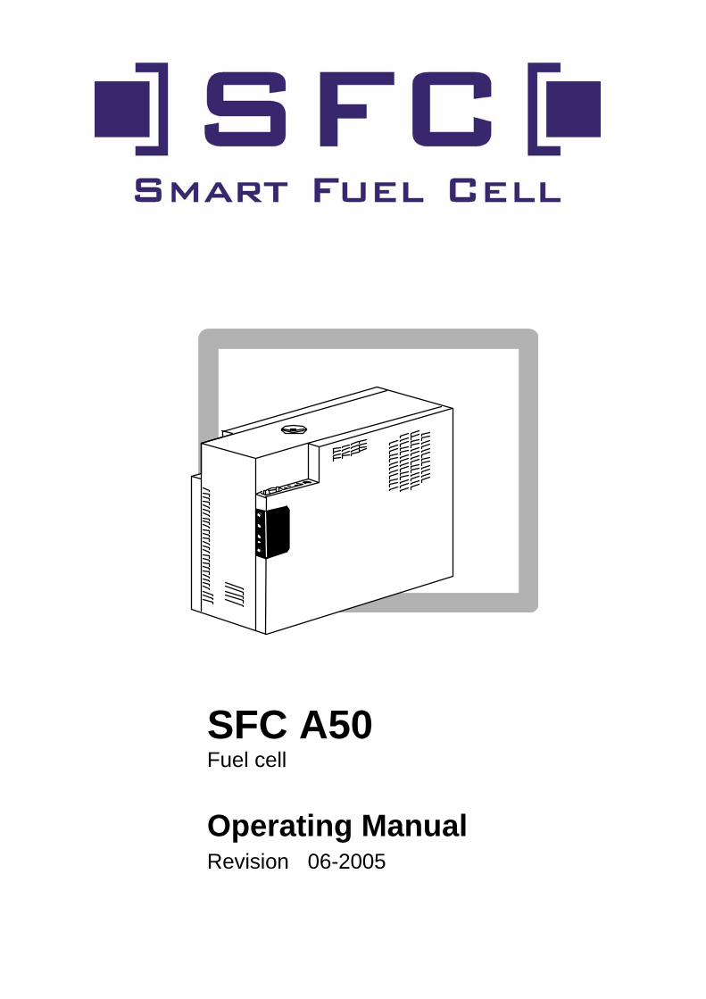
SFC A50 Fuel cell
Operating Manual Revision 06-2005

2
3
1. Introduction
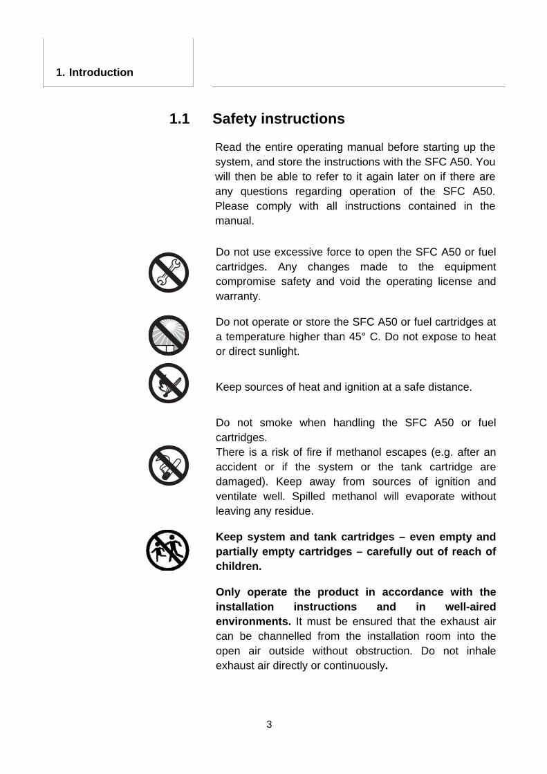
Safety instructions 1.1 Read the entire operating manual before starting up the system, and store the instructions with the SFC A50. You will then be able to refer to it again later on if there are any questions regarding operation of the SFC A50. Please comply with all instructions contained in the manual.
Do not use excessive force to open the SFC A50 or fuel cartridges. Any changes made to the equipment compromise safety and void the operating license and warranty.
Do not operate or store the SFC A50 or fuel cartridges at a temperature higher than 45° C. Do not expose to heat or direct sunlight.
Keep sources of heat and ignition at a safe distance.
Do not smoke when handling the SFC A50 or fuel cartridges. There is a risk of fire if methanol escapes (e.g. after an accident or if the system or the tank cartridge are damaged). Keep away from sources of ignition and ventilate well. Spilled methanol will evaporate without leaving any residue.
Keep system and tank cartridges – even empty and partially empty cartridges – carefully out of reach of children.
Only operate the product in accordance with the installation instructions and in well-aired environments. It must be ensured that the exhaust air can be channelled from the installation room into the open air outside without obstruction. Do not inhale exhaust air directly or continuously.
4
Methanol is poisonous. Do not inhale, swallow or allow it to come into contact with skin. There is a real risk of serious injury due to inhalation, contact with skin or swallowing. In case of accident or nausea, immediately seek medical assistance and present the fuel cartridge label or operating manual (there is a methanol safety data sheet in the appendix at the end of this manual).
The exhaust air in the system can contain noxious matter. Do not inhale exhaust air directly or continuously but conduct it into the open air outside by means of the exhaust air tube included in the scope of supply.
Damage can occur if used inappropriately or if connected incorrectly to other electrical devices.
Follow all safety instructions and be sure to comply with all warnings printed in bold font to minimize risk of injury to yourself and others.
1. Introduction
5
1.2 Using the fuel cell in compliance with regulations
The SFC A50 is an automatic charger for 12 V lead-acid batteries. The SFC A50 may only be used to charge batteries which comply with the technical requirements.
The SFC A50 may be used in stationary applications as well as in boats and vehicles, provided it is applied in accordance with the specifications (e.g., permissible temperature range). It may only be operated using original Smart Fuel Cell cartridges.
The SFC A50 is not designed for use as an emergency power supply for vital life-support equipment.
1.3 Declaration of Conformity
SFC Smart Fuel Cell AG, Eugen-Sänger-Ring 4, 85649 Brunnthal-Nord, hereby declares that the product SFC A50 conforms to the EC Guideline 89/336/EWG as it is relating to electromagnetic compatibility. The following harmonized standards were applied: DIN EN 61000-6-1, DIN EN 61000-6-3
1. Introduction
6
2. Table of Contents
1. Introduction 3
1.1 Safety instructions 3 1.2 Using the fuel cell in compliance with regulations 5 1.3 Declaration of Conformity 5
2. Table of Contents 6 3. Construction 7
3.1 Package contents 7 3.2 Overview 7 3.3 Operating panel 8 3.4 Technical specifications 9
4. Installation 11 4.1 Mounting location 11 4.2 Mounting 14 4.3 Installing the exhaust tube 15 4.4 Electrical connections 16 4.5 Cooling-air supply 18 4.6 Optional remote control 19
5. Operation 20 5.1 Connecting a fuel cartridge 20 5.2 Operating modes 21 5.3 Switching the device on, ready to operate (standby) 21 5.4 Charge process 22 5.5 Shutdown 22 5.6 Freeze protection 23 5.7 Long-term shutdown 24
6. Maintenance 26 6.1 Service 26 6.2 Cleaning 26
7. Trouble Shooting 27 7.1 Safety 27 7.2 Fault indications - causes and solutions 27 7.3 Fuse replacement 30 7.4 Replenishing the process medium 31
8. Appendix 32 8.1 Accessories 32 8.2 Output characteristic 33 8.3 Methanol safety data sheet 33
7
3. Construction
Package contents 3.1
The SFC A50 package includes the following items:
SFC A50 Mounting plate including two fastening screws Fuel-cartridge holder Exhaust tube Connecting cable Spare fuse Process medium Documents
Overview 3.2
1
3
2
4
5
6
9
8 7
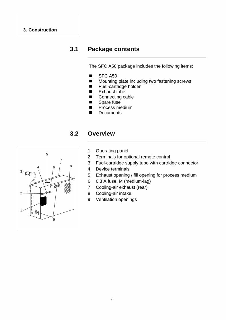
1 Operating panel 2 Terminals for optional remote control 3 Fuel-cartridge supply tube with cartridge connector 4 Device terminals 5 Exhaust opening / fill opening for process medium 6 6.3 A fuse, M (medium-lag) 7 Cooling-air exhaust (rear) 8 Cooling-air intake 9 Ventilation openings
8
3. Construction
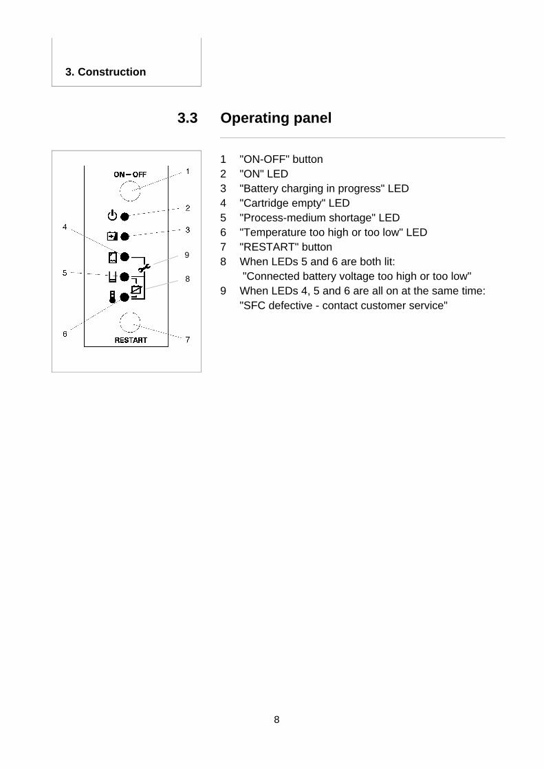
Operating panel 3.3
9
8
1 "ON-OFF" button 2 "ON" LED 3 "Battery charging in progress" LED 4 "Cartridge empty" LED 5 "Process-medium shortage" LED 6 "Temperature too high or too low" LED 7 "RESTART" button 8 When LEDs 5 and 6 are both lit: "Connected battery voltage too high or too low" 9 When LEDs 4, 5 and 6 are all on at the same time:
"SFC defective - contact customer service"

9
3. Construction
3.4 Technical specifications
Performance data
Power rating 34 W... 50 W
Voltage 10.5 … 14.0 V, compatible with 12 V lead-acid batteries (wet cell or gel cell with 40 – 200 Ah capacitance)
Consumption about 1.3 litres of methanol per kWh
Features
Power output connection 12 V output including sensor to automatically charge a 12 V lead-acid battery
Control interface sub-D plug to connect an external operating panel (available as optional component)
Electrical protection electronic shutdown on overload 250V, 6.3 A fuse, M (medium-lag) for short-circuit protection
General specifications
Noise emission about 47 dB(A) at a distance of 1 m during fuel cell operation
Maximum dimensions 380 mm x 260 mm x 150 mm (WxHxD)
Weight approx. 8 kg
Ambient conditions
Operating temperature –20 °C … +40 °C
Storage temperature +1 °C … +45 °C
Humidity of air 20% … 90%
10
3. Construction
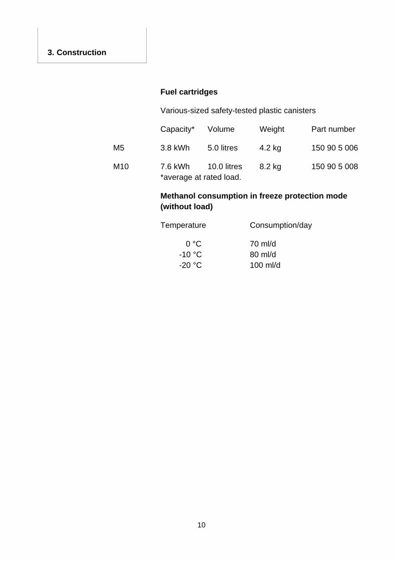
Fuel cartridges
Various-sized safety-tested plastic canisters
Capacity* Volume Weight Part number
M5 3.8 kWh 5.0 litres 4.2 kg 150 90 5 006
M10 7.6 kWh 10.0 litres 8.2 kg 150 90 5 008 *average at rated load.
Methanol consumption in freeze protection mode (without load)
Temperature Consumption/day
0 °C 70 ml/d -10 °C 80 ml/d -20 °C 100 ml/d
11
4. Installation
When used in vehicles and boats, the SFC A50 and the methanol cartridges shall be securely tied or bolted down to avoid accidents.
The SFC A50 shall not be installed in hazardous locations (explosion risk).
The SFC A50 is not waterproof. Do not install where water can enter the equipment.
Children shall not be permitted to access the SFC A50 and the fuel cartridges, and it shall be protected from direct sunlight and exposure to temperatures exceeding 45 °C.
Mounting location 4.1
Ensure that temperatures will not exceed -20° C. and +40° C. where the equipment is to be installed. Avoid installation in small or confined spaces that are subject to heat build-up from the warm exhaust air. We recommend maintaining a clearance of about 5 cm between the wall and cooling-air exhaust if the equipment is installed in an enclosed space.
A separate cooling-air tube is available as an option (see Chapter 4.7). This enables the heated SFC A50 cooling air to be properly exhausted and enables the device also to be operated in a very confined space.
12
4. Installation
For installations where ambient temperature is less than 3° C., the SFC A50 shall always have sufficient methanol to allow the freeze protection to operate (see Chapter 5.5). A 12 V battery shall also be connected. If you are unable to regularly connect filled cartridges, the SFC A50 shall be stored at a temperature higher than 3° C; therefore, ensure that the device can easily be removed from its installation location in winter time.
Irrespective of the ambient temperature, small quantities of condensate (water) can escape from the housing.
The SFC A50 shall only be installed in an upright position. The equipment may not operate reliably or be damaged if it is continuously inclined at an angle of more than 20°.
The SFC A50 consumes about the same amount of air oxygen as a human (about 60 l/h or 86 g/h O2) when it operates. The SFC A50 shall therefore be installed in a well-ventilated location. It also emits small amounts of humid air and carbon dioxide via the exhaust opening. The amount is similar to what humans exhale (about 40 l/h or 80 g/h CO2) Use the exhaust tube to channel the exhaust air from the installation room to outside.
The operating panel, the electrical connections, the fill opening for the process medium and the fuel cartridge should be easy accessible.
Install the SFC A50 and the fuel cartridge at the same level.
Ensure that the fuel cartridge installation location is within reach of the cartridge supply tube (20 cm) and that the path of the tube is not subject to squishing or kinking.
The integrity of the fuel cartridge supply tube and the exhaust tube must be maintained. Do not use any other type of replacement tubing.
13
4. Installation
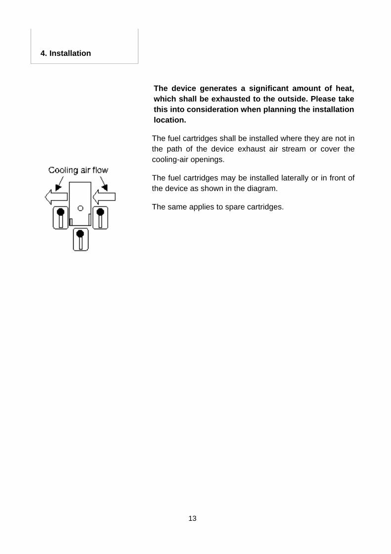
The device generates a significant amount of heat, which shall be exhausted to the outside. Please take this into consideration when planning the installation location.
The fuel cartridges shall be installed where they are not in the path of the device exhaust air stream or cover the cooling-air openings.
The fuel cartridges may be installed laterally or in front of the device as shown in the diagram.
The same applies to spare cartridges.
14
4. Installation
Mounting 4.2
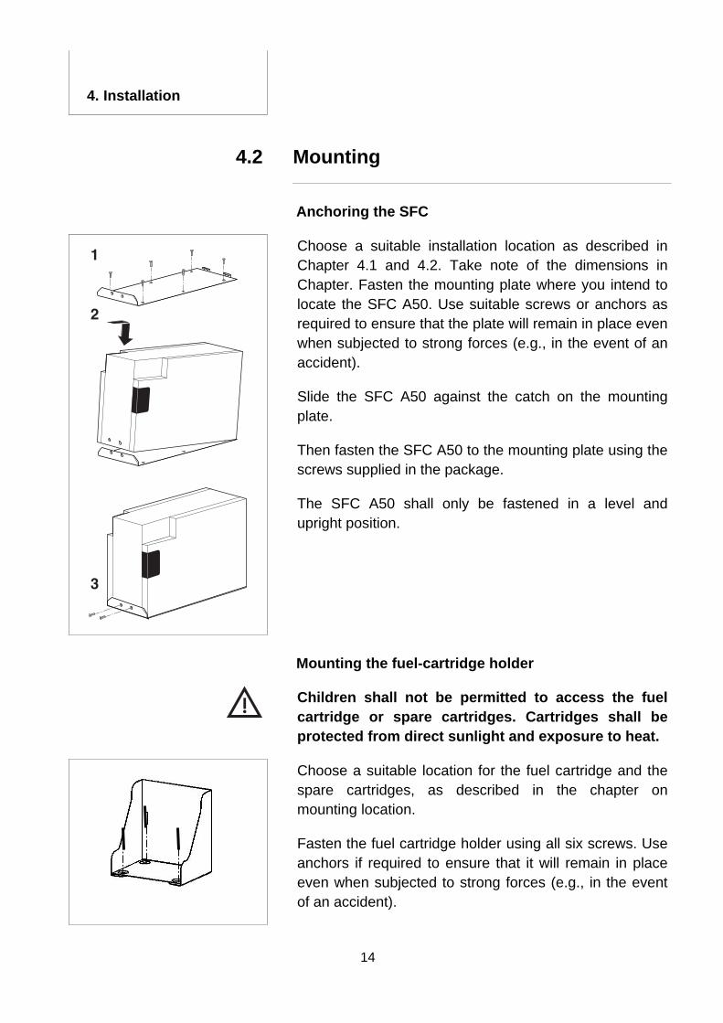
Anchoring the SFC
SFC
1200
Choose a suitable installation location as described in Chapter 4.1 and 4.2. Take note of the dimensions in Chapter. Fasten the mounting plate where you intend to locate the SFC A50. Use suitable screws or anchors as required to ensure that the plate will remain in place even when subjected to strong forces (e.g., in the event of an accident).
Slide the SFC A50 against the catch on the mounting plate.
Then fasten the SFC A50 to the mounting plate using the screws supplied in the package.
The SFC A50 shall only be fastened in a level and upright position.
Mounting the fuel-cartridge holder
Children shall not be permitted to access the fuel cartridge or spare cartridges. Cartridges shall be protected from direct sunlight and exposure to heat.
Choose a suitable location for the fuel cartridge and the spare cartridges, as described in the chapter on mounting location.
Fasten the fuel cartridge holder using all six screws. Use anchors if required to ensure that it will remain in place even when subjected to strong forces (e.g., in the event of an accident).
15
4. Installation
Installing the exhaust tube 4.3
To ensure that the SFC A50 will function perfectly and reliably, an exhaust air tube must be connected. Use only the SFC exhaust air tube included in the delivery. Always channel the exhaust air out of the installation room or location to the open air outside. The humid exhaust air may exceed 60°C during operation. There is a risk of burn injuries. The exhaust air can contain noxious matter. Do not inhale exhaust air directly or continuously.
Note that the exhaust air contains slight quantities of water vapour, which may condense in the tube. Accordingly, drops of water can form in the tube. For this reason too, the exhaust tube should always lead from the installation space into the open air outside.
Push the tube supplied onto the exhaust-air opening. It may be cut to the required length.
Route the tube so that it leads from the installation space to outside.
Make sure that there are no kinks in the exhaust-air tube and that it is not plugged, and that exhaust air can flow freely.
Ensure that the end of the tube cannot become closed or plugged. The tube shall not create a siphon. Keep the maximum length of the exhaust tube below 50 cm to prevent it from freezing up in winter. The maximum length shall not exceed 150 cm.
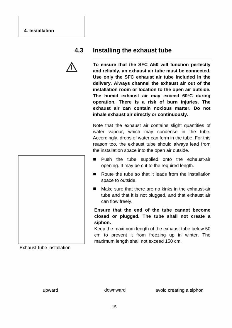
Exhaust-tube installation
downward upward avoid creating a siphon
16
4. Installation
Electrical connections 4.4
Alternative A: Connection using the supplied connecting cable
Work on electrical installations shall only be carried out by qualified electricians in accordance with relevant electrical code requirements.
Any wiring connected to the system shall be approved for the appropriate voltage and insulation levels and any contact points shall be safe to touch. No bare wires or exposed contacts are permitted.
Use the supplied connecting cable to connect the device. The cable shall only be connected to the battery from a short-circuit protected electrical circuit or via a fuse (available as an option). This provides protection if a short-circuit occurs when the SFC A50 is disconnected from the battery while the surroundings are damp.
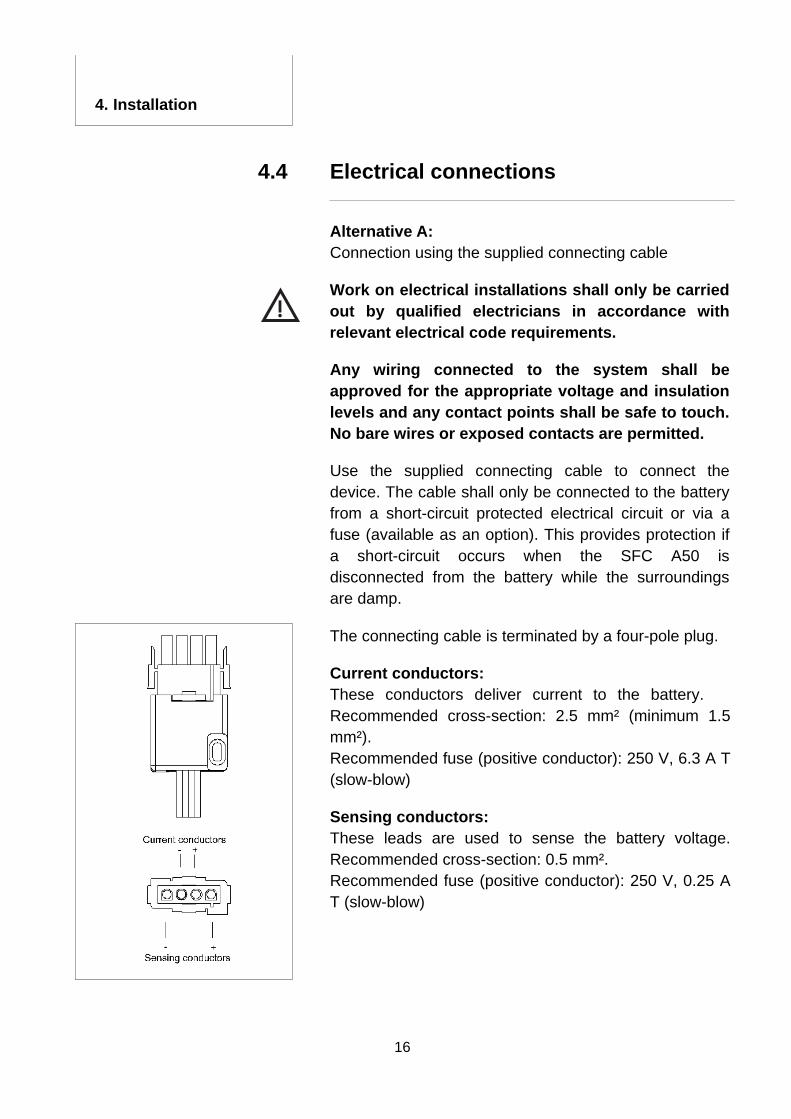
The connecting cable is terminated by a four-pole plug.
Current conductors: These conductors deliver current to the battery. Recommended cross-section: 2.5 mm² (minimum 1.5 mm²). Recommended fuse (positive conductor): 250 V, 6.3 A T (slow-blow)
Sensing conductors: These leads are used to sense the battery voltage.Recommended cross-section: 0.5 mm². Recommended fuse (positive conductor): 250 V, 0.25 A T (slow-blow)
17
4. Installation
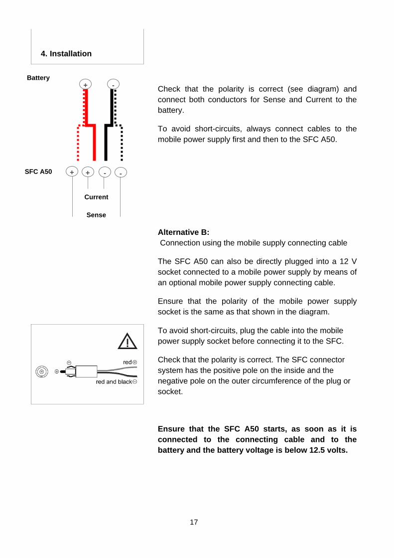
+
Current Sense
Battery
SFC A50 + - -
+ - Check that the polarity is correct (see diagram) and connect both conductors for Sense and Current to the battery.
To avoid short-circuits, always connect cables to the mobile power supply first and then to the SFC A50.
Alternative B: Connection using the mobile supply connecting cable
The SFC A50 can also be directly plugged into a 12 V socket connected to a mobile power supply by means of an optional mobile power supply connecting cable.
Ensure that the polarity of the mobile power supply socket is the same as that shown in the diagram.
To avoid short-circuits, plug the cable into the mobile power supply socket before connecting it to the SFC.
Check that the polarity is correct. The SFC connector system has the positive pole on the inside and the negative pole on the outer circumference of the plug or socket.
Ensure that the SFC A50 starts, as soon as it is connected to the connecting cable and to the battery and the battery voltage is below 12.5 volts.
18
4. Installation
Cooling-air supply 4.5
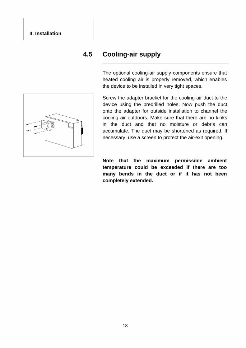
The optional cooling-air supply components ensure that heated cooling air is properly removed, which enables the device to be installed in very tight spaces.
Screw the adapter bracket for the cooling-air duct to the device using the predrilled holes. Now push the duct onto the adapter for outside installation to channel the cooling air outdoors. Make sure that there are no kinks in the duct and that no moisture or debris can accumulate. The duct may be shortened as required. If necessary, use a screen to protect the air-exit opening.
Note that the maximum permissible ambient temperature could be exceeded if there are too many bends in the duct or if it has not been completely extended.
19
4. Installation
Optional remote control 4.6
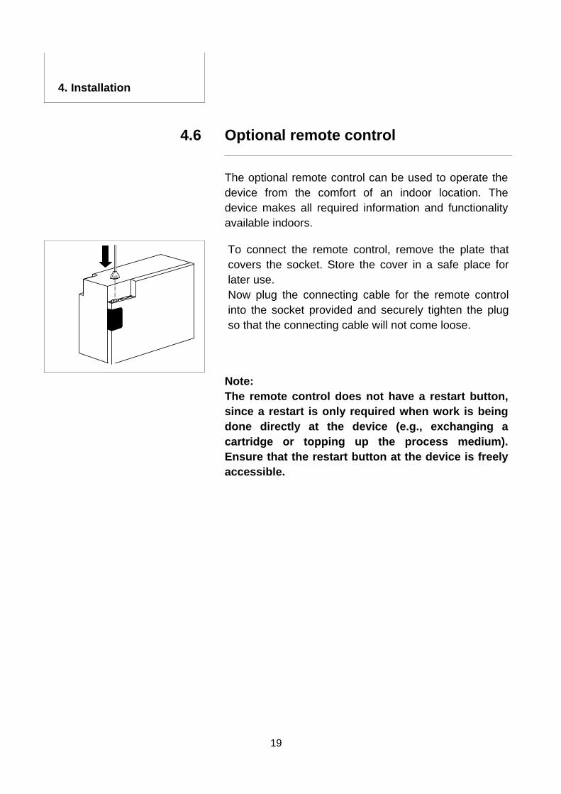
The optional remote control can be used to operate the device from the comfort of an indoor location. The device makes all required information and functionality available indoors.
To connect the remote control, remove the plate that covers the socket. Store the cover in a safe place for later use. Now plug the connecting cable for the remote control into the socket provided and securely tighten the plug so that the connecting cable will not come loose.
Note: The remote control does not have a restart button, since a restart is only required when work is being done directly at the device (e.g., exchanging a cartridge or topping up the process medium). Ensure that the restart button at the device is freely accessible.
20
5. Operation
Connecting a fuel cartridge 5.1
Use only original SFC fuel cartridges (see accessories for part number) to avoid compromising safety. Do not smoke while replacing fuel cartridges! Do not expose fuel cartridges to temperatures exceeding 45 °C.
The fuel cartridge shall not be positioned in front of the SFC A50 cooling-air exhaust opening, since the device generates heat.
Note: The yellow LED lights when the cartridge is depleted. The cartridge may be replaced while the system is operating.
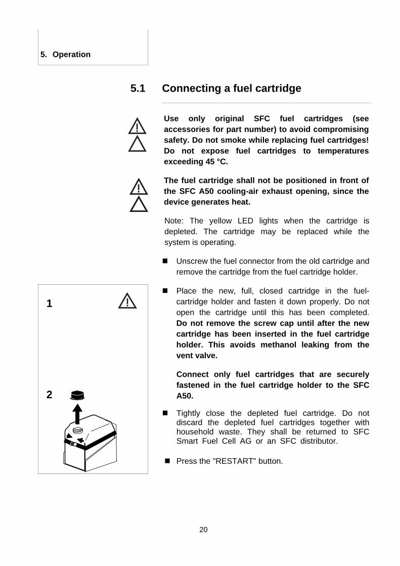
Unscrew the fuel connector from the old cartridge and remove the cartridge from the fuel cartridge holder.
1
2
Place the new, full, closed cartridge in the fuel-cartridge holder and fasten it down properly. Do not open the cartridge until this has been completed.Do not remove the screw cap until after the new cartridge has been inserted in the fuel cartridge holder. This avoids methanol leaking from the vent valve.
Connect only fuel cartridges that are securely fastened in the fuel cartridge holder to the SFC A50.
Tightly close the depleted fuel cartridge. Do not discard the depleted fuel cartridges together with household waste. They shall be returned to SFC Smart Fuel Cell AG or an SFC distributor.
Press the "RESTART" button.
21
5. Operation
Operating modes 5.2
Before starting the SFC A50, ensure that it is properly connected.
Do not operate the SFC above 40° C or below -20° C.
Operating modes
The SFC A50 has four operating modes.
1. Standby (ready to operate) 2. Charge 3. OFF 4. Automatic freeze protection
Ensure that a full fuel cartridge is connected to the device.
5.3
Switching the device on, ready to operate (standby)
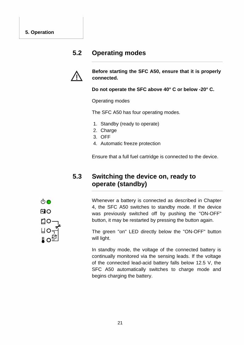
Whenever a battery is connected as described in Chapter 4, the SFC A50 switches to standby mode. If the device was previously switched off by pushing the "ON-OFF" button, it may be restarted by pressing the button again.
The green "on" LED directly below the "ON-OFF" button will light.
In standby mode, the voltage of the connected battery is continually monitored via the sensing leads. If the voltage of the connected lead-acid battery falls below 12.5 V, the SFC A50 automatically switches to charge mode and begins charging the battery.
22
5. Operation
Charge process 5.4
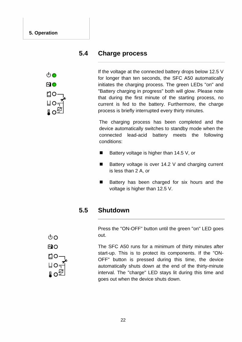
If the voltage at the connected battery drops below 12.5 V for longer than ten seconds, the SFC A50 automatically initiates the charging process. The green LEDs "on" and "Battery charging in progress" both will glow. Please note that during the first minute of the starting process, no current is fed to the battery. Furthermore, the charge process is briefly interrupted every thirty minutes.
The charging process has been completed and the device automatically switches to standby mode when the connected lead-acid battery meets the following conditions:
Battery voltage is higher than 14.5 V, or
Battery voltage is over 14.2 V and charging current is less than 2 A, or
Battery has been charged for six hours and the voltage is higher than 12.5 V.
Shutdown 5.5
Press the "ON-OFF" button until the green "on" LED goes out.
The SFC A50 runs for a minimum of thirty minutes after start-up. This is to protect its components. If the "ON-OFF" button is pressed during this time, the device automatically shuts down at the end of the thirty-minute interval. The "charge" LED stays lit during this time and goes out when the device shuts down.
23
5. Operation
The battery voltage is not monitored when the device is switched off.
Note that the SFC A50 cannot be started if the voltage at the connected battery falls below 10.5 V.
Freeze protection 5.6
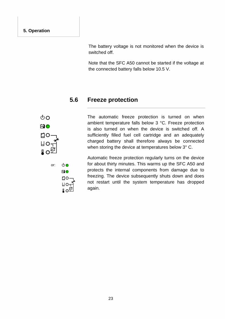
The automatic freeze protection is turned on when ambient temperature falls below 3 °C. Freeze protection is also turned on when the device is switched off. A sufficiently filled fuel cell cartridge and an adequately charged battery shall therefore always be connected when storing the device at temperatures below 3° C.
Automatic freeze protection regularly turns on the device for about thirty minutes. This warms up the SFC A50 and protects the internal components from damage due to freezing. The device subsequently shuts down and does not restart until the system temperature has dropped again.
or:
24
5. Operation
Long-term shutdown 5.7
Press the "ON-OFF" button if the SFC A50 is still switched on.
The "on" LED goes out.
Unplug the connecting plug from the SFC A50.
Protect the plug from moisture (short-circuit risk!).
Do not smoke when working on the SFC A50 or fuel cartridges.
Unscrew the fuel connector from the fuel cartridge and screw the cap onto the cartridge.
Store the SFC A50 in a cool location but not at temperatures lower than 0° C. The freeze protection only works when a filled fuel cartridge and an adequately charged battery are connected. Protect the fuel connector from contaminants.
The SFC A50 shall only be shipped in its original carton container. Ship the SFC A50 only in an upright position.
25
5. Operation
2
1
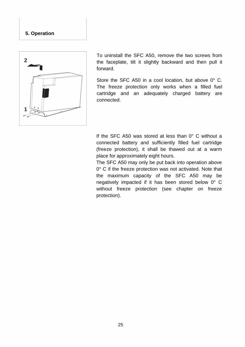
To uninstall the SFC A50, remove the two screws from the faceplate, tilt it slightly backward and then pull it forward.
Store the SFC A50 in a cool location, but above 0° C. The freeze protection only works when a filled fuel cartridge and an adequately charged battery are connected.
If the SFC A50 was stored at less than 0° C without a connected battery and sufficiently filled fuel cartridge (freeze protection), it shall be thawed out at a warm place for approximately eight hours. The SFC A50 may only be put back into operation above 0° C if the freeze protection was not activated. Note that the maximum capacity of the SFC A50 may be negatively impacted if it has been stored below 0° C without freeze protection (see chapter on freeze protection).
26
6. Maintenance
Service 6.1
Do not open the fuel cell! Unauthorized opening can compromise safe operation and voids all warranties. The SFC A50 does not contain any parts that can be repaired or maintained by the owner.
Under normal operating conditions the SFC A50 is maintenance-free. Please contact SFC Smart Fuel Cell AG, if you wish to operate the SFC A50 under extreme conditions or at other than rated specifications. The address is on the back of the envelope.
Cleaning 6.2
Switch off the SFC A50 and remove the connecting plug before cleaning the device.
The SFC A50 is not waterproof. Ensure that no moisture is able to enter the equipment.
Use only mild cleaning solutions and a damp, soft cloth to clean the SFC A50.
After cleaning, reattach the connecting plug so that the freeze protection remains active.
27
7. Trouble Shooting
Safety 7.1
Do not open the fuel cell! The SFC A50 does not contain any parts that can be repaired by the owner.
Contact SFC Smart Fuel Cell AG (address on the back of the envelope) if you are not able to solve a problem using the instructions in this operating manual.
7.2 Fault indications - causes and solutions
Depending on the previous operating state, the green
ON-LED may also be lit.
Description Possible cause / solution
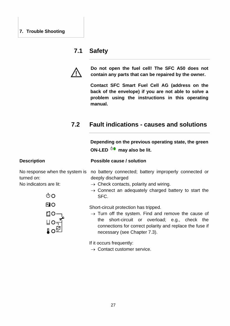
No response when the system is turned on: No indicators are lit:
no battery connected; battery improperly connected or deeply discharged → Check contacts, polarity and wiring. → Connect an adequately charged battery to start the
SFC.
Short-circuit protection has tripped. → Turn off the system. Find and remove the cause of
the short-circuit or overload; e.g., check the connections for correct polarity and replace the fuse if necessary (see Chapter 7.3).
If it occurs frequently: → Contact customer service.
28
7. Trouble Shooting
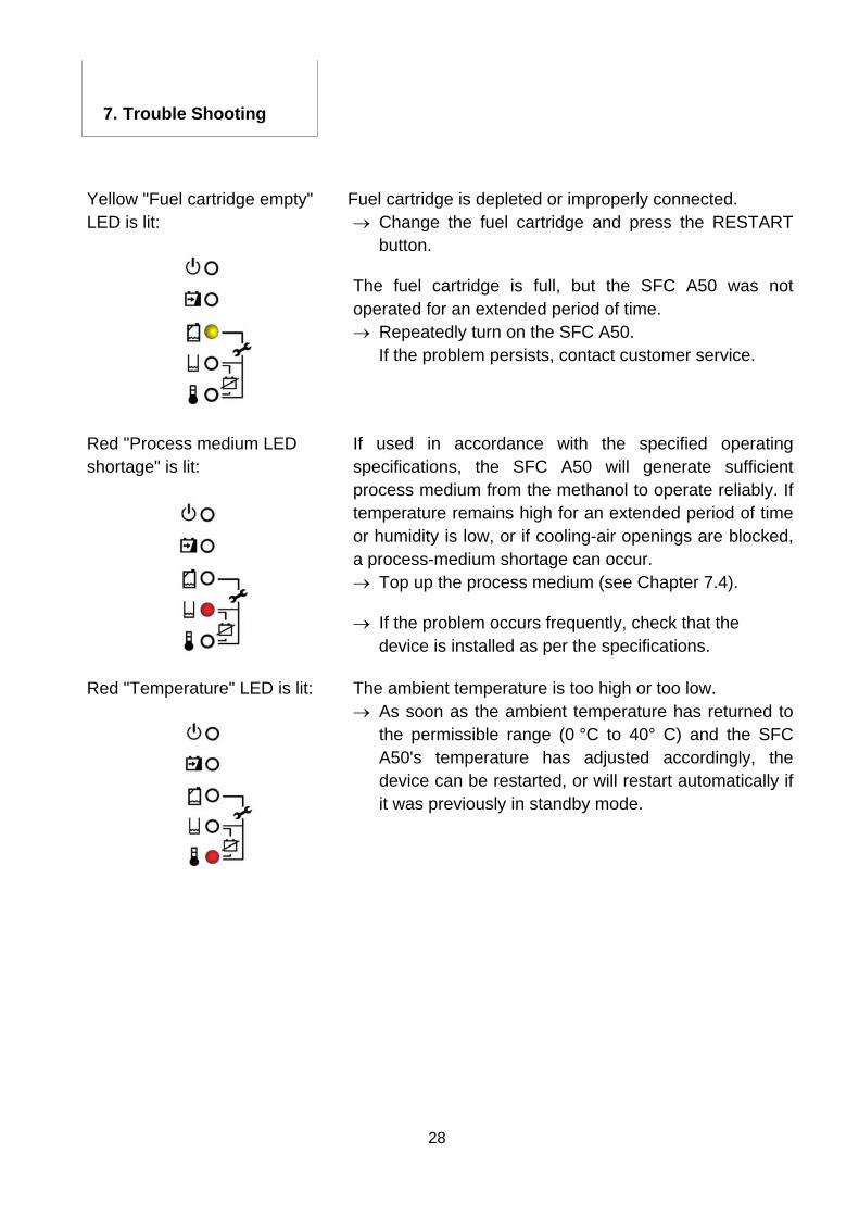
Fuel cartridge is depleted or improperly connected. Yellow "Fuel cartridge empty" LED is lit: → Change the fuel cartridge and press the RESTART
button.
The fuel cartridge is full, but the SFC A50 was not operated for an extended period of time. → Repeatedly turn on the SFC A50.
If the problem persists, contact customer service.
Red "Process medium LED shortage" is lit:
If used in accordance with the specified operating specifications, the SFC A50 will generate sufficient process medium from the methanol to operate reliably. If temperature remains high for an extended period of time or humidity is low, or if cooling-air openings are blocked, a process-medium shortage can occur. → Top up the process medium (see Chapter 7.4).
→ If the problem occurs frequently, check that the device is installed as per the specifications.
Red "Temperature" LED is lit: The ambient temperature is too high or too low. → As soon as the ambient temperature has returned to
the permissible range (0 °C to 40° C) and the SFC A50's temperature has adjusted accordingly, the device can be restarted, or will restart automatically if it was previously in standby mode.
29
7. Trouble Shooting
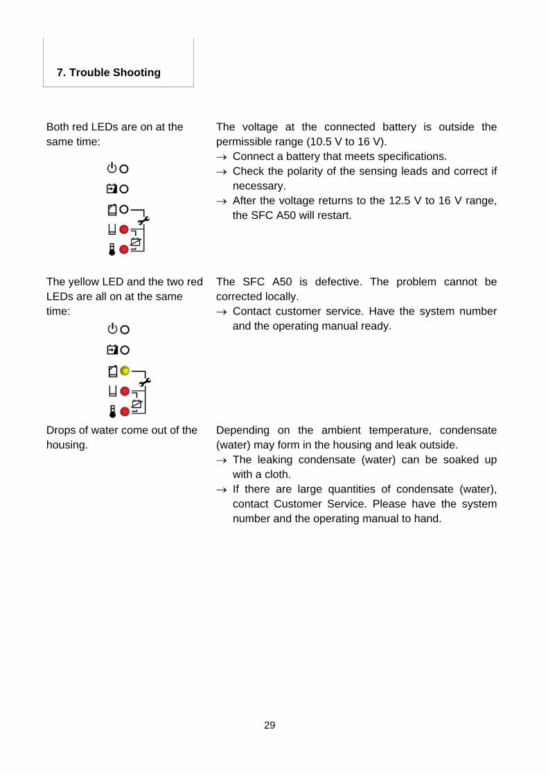
Both red LEDs are on at the same time:
The voltage at the connected battery is outside the permissible range (10.5 V to 16 V). → Connect a battery that meets specifications. → Check the polarity of the sensing leads and correct if
necessary. → After the voltage returns to the 12.5 V to 16 V range,
the SFC A50 will restart.
The yellow LED and the two red LEDs are all on at the same time:
The SFC A50 is defective. The problem cannot be corrected locally. → Contact customer service. Have the system number
and the operating manual ready.
Drops of water come out of the housing.
Depending on the ambient temperature, condensate (water) may form in the housing and leak outside. → The leaking condensate (water) can be soaked up
with a cloth. → If there are large quantities of condensate (water),
contact Customer Service. Please have the system number and the operating manual to hand.
30
7. Trouble Shooting
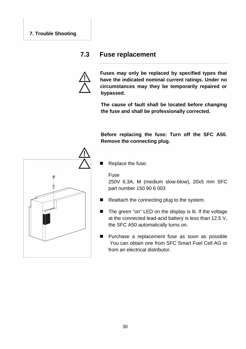
Fuse replacement 7.3
Fuses may only be replaced by specified types that have the indicated nominal current ratings. Under no circumstances may they be temporarily repaired or bypassed.
The cause of fault shall be located before changing the fuse and shall be professionally corrected.
Before replacing the fuse: Turn off the SFC A50. Remove the connecting plug.
Replace the fuse:
Fuse 250V 6.3A, M (medium slow-blow), 20x5 mm SFC part number 150 90 6 003
Reattach the connecting plug to the system.
The green "on" LED on the display is lit. If the voltage at the connected lead-acid battery is less than 12.5 V, the SFC A50 automatically turns on.
Purchase a replacement fuse as soon as possible You can obtain one from SFC Smart Fuel Cell AG or from an electrical distributor.
31
7. Trouble Shooting
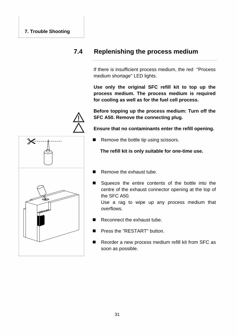
Replenishing the process medium 7.4
If there is insufficient process medium, the red "Process medium shortage" LED lights.
Use only the original SFC refill kit to top up the process medium. The process medium is required for cooling as well as for the fuel cell process.
Before topping up the process medium: Turn off the SFC A50. Remove the connecting plug.
Ensure that no contaminants enter the refill opening.
Remove the bottle tip using scissors.
The refill kit is only suitable for one-time use.
Remove the exhaust tube.
Squeeze the entire contents of the bottle into the centre of the exhaust connector opening at the top of the SFC A50.
Use a rag to wipe up any process medium that overflows.
Reconnect the exhaust tube.
Press the "RESTART" button.
Reorder a new process medium refill kit from SFC as soon as possible.
32
8. Appendix
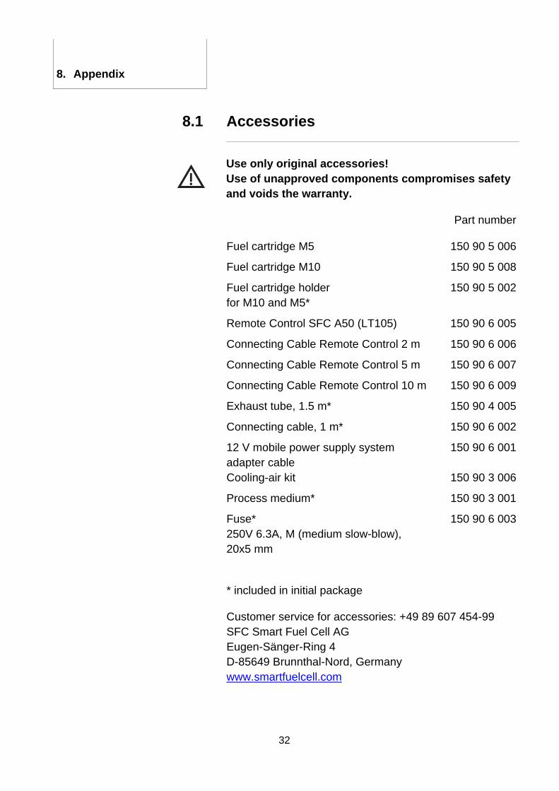
Accessories 8.1
Use only original accessories! Use of unapproved components compromises safety and voids the warranty.
Part number
Fuel cartridge M5 150 90 5 006
Fuel cartridge M10 150 90 5 008
Fuel cartridge holder for M10 and M5*
150 90 5 002
Remote Control SFC A50 (LT105) 150 90 6 005
Connecting Cable Remote Control 2 m 150 90 6 006
Connecting Cable Remote Control 5 m 150 90 6 007
Connecting Cable Remote Control 10 m 150 90 6 009
Exhaust tube, 1.5 m* 150 90 4 005
Connecting cable, 1 m* 150 90 6 002
12 V mobile power supply system adapter cable
150 90 6 001
Cooling-air kit 150 90 3 006
Process medium* 150 90 3 001
Fuse* 250V 6.3A, M (medium slow-blow), 20x5 mm
150 90 6 003
* included in initial package
Customer service for accessories: +49 89 607 454-99 SFC Smart Fuel Cell AG Eugen-Sänger-Ring 4 D-85649 Brunnthal-Nord, Germany www.smartfuelcell.com
33
8. Appendix
Output characteristic 8.2
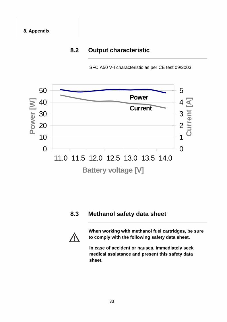
SFC A50 V-I characteristic as per CE test 09/2003
Spannung 11.0 11.5 12.0 12.5 13.0 13.5 14.0Leistung 50.7 48.8 49.7 51 50.5 50.9 48.1Strom 4.6 4.3 4.1 4.1 3.9 3.8 3.5
01020304050
11.0 11.5 12.0 12.5 13.0 13.5 14.0Battery voltage [V]
Pow
er [W
]
012345
Cur
rent
[A]Power
Current
Methanol safety data sheet 8.3
When working with methanol fuel cartridges, be sure to comply with the following safety data sheet.
In case of accident or nausea, immediately seek medical assistance and present this safety data sheet.
Material safety data sheet Methanol
34
Gemäß Richtlinie 91/155/EWG der Kommission
der Europäischen Gemeinschaften Issue date : September 2002
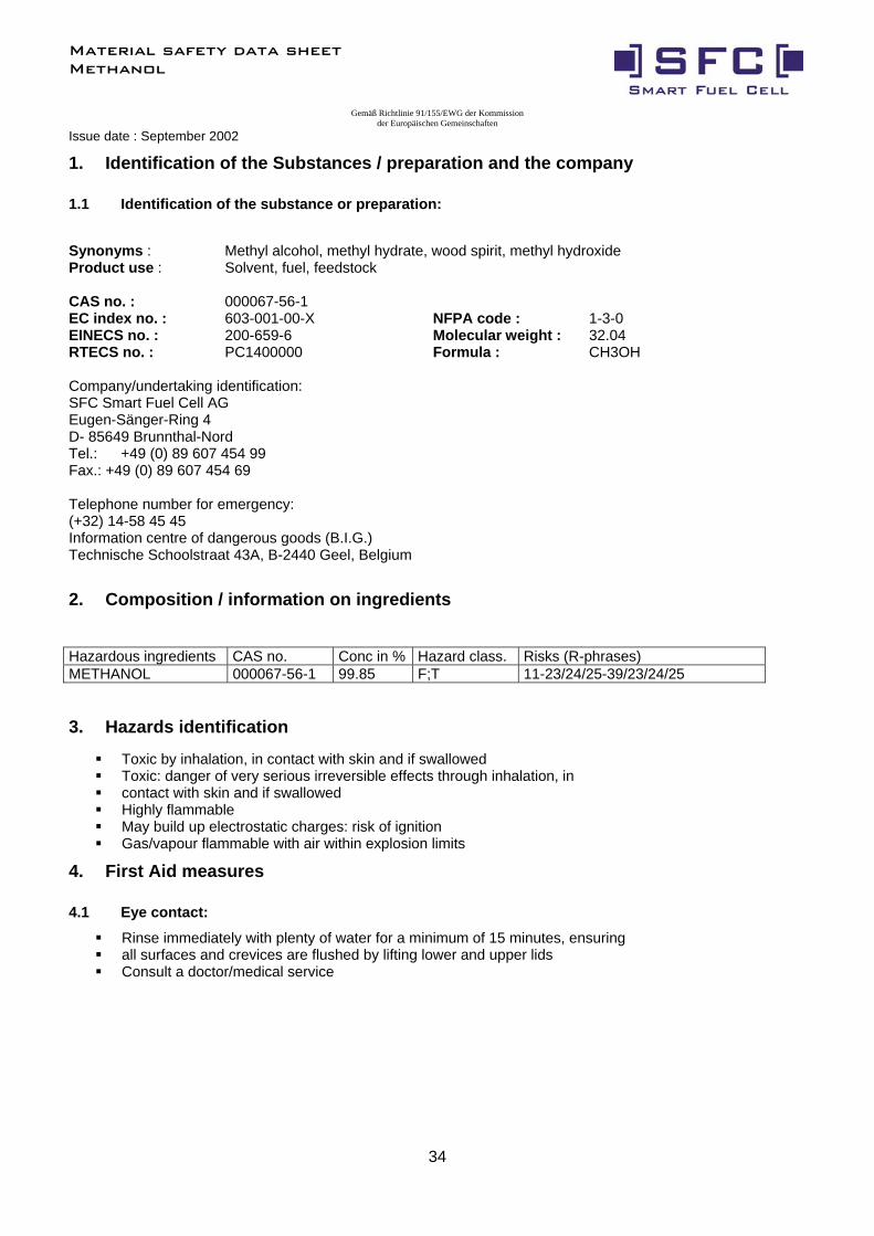
1. Identification of the Substances / preparation and the company
1.1 Identification of the substance or preparation:
Synonyms : Methyl alcohol, methyl hydrate, wood spirit, methyl hydroxide Product use : Solvent, fuel, feedstock CAS no. : 000067-56-1 EC index no. : 603-001-00-X NFPA code : 1-3-0 EINECS no. : 200-659-6 Molecular weight : 32.04 RTECS no. : PC1400000 Formula : CH3OH Company/undertaking identification: SFC Smart Fuel Cell AG Eugen-Sänger-Ring 4 D- 85649 Brunnthal-Nord Tel.: +49 (0) 89 607 454 99 Fax.: +49 (0) 89 607 454 69 Telephone number for emergency: (+32) 14-58 45 45 Information centre of dangerous goods (B.I.G.) Technische Schoolstraat 43A, B-2440 Geel, Belgium
2. Composition / information on ingredients
Hazardous ingredients CAS no. Conc in % Hazard class. Risks (R-phrases) METHANOL 000067-56-1 99.85 F;T 11-23/24/25-39/23/24/25
3. Hazards identification
Toxic by inhalation, in contact with skin and if swallowed Toxic: danger of very serious irreversible effects through inhalation, in contact with skin and if swallowed Highly flammable May build up electrostatic charges: risk of ignition Gas/vapour flammable with air within explosion limits
4. First Aid measures
4.1 Eye contact:
Rinse immediately with plenty of water for a minimum of 15 minutes, ensuring all surfaces and crevices are flushed by lifting lower and upper lids Consult a doctor/medical service
Material safety data sheet Methanol
35
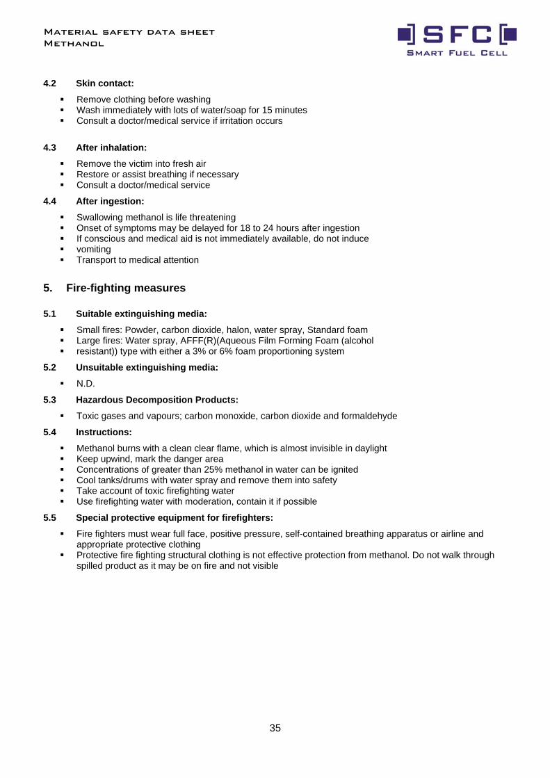
4.2 Skin contact:
Remove clothing before washing Wash immediately with lots of water/soap for 15 minutes Consult a doctor/medical service if irritation occurs
4.3 After inhalation:
Remove the victim into fresh air Restore or assist breathing if necessary Consult a doctor/medical service
4.4 After ingestion:
Swallowing methanol is life threatening Onset of symptoms may be delayed for 18 to 24 hours after ingestion If conscious and medical aid is not immediately available, do not induce vomiting Transport to medical attention
5. Fire-fighting measures
5.1 Suitable extinguishing media:
Small fires: Powder, carbon dioxide, halon, water spray, Standard foam Large fires: Water spray, AFFF(R)(Aqueous Film Forming Foam (alcohol resistant)) type with either a 3% or 6% foam proportioning system
5.2 Unsuitable extinguishing media:
N.D.
5.3 Hazardous Decomposition Products:
Toxic gases and vapours; carbon monoxide, carbon dioxide and formaldehyde
5.4 Instructions:
Methanol burns with a clean clear flame, which is almost invisible in daylight Keep upwind, mark the danger area Concentrations of greater than 25% methanol in water can be ignited Cool tanks/drums with water spray and remove them into safety Take account of toxic firefighting water Use firefighting water with moderation, contain it if possible
5.5 Special protective equipment for firefighters:
Fire fighters must wear full face, positive pressure, self-contained breathing apparatus or airline and appropriate protective clothing
Protective fire fighting structural clothing is not effective protection from methanol. Do not walk through spilled product as it may be on fire and not visible
Material safety data sheet Methanol
36
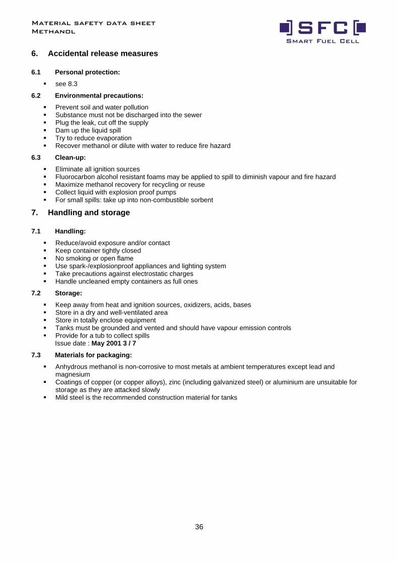
6. Accidental release measures
6.1 Personal protection:
see 8.3
6.2 Environmental precautions:
Prevent soil and water pollution Substance must not be discharged into the sewer Plug the leak, cut off the supply Dam up the liquid spill Try to reduce evaporation Recover methanol or dilute with water to reduce fire hazard
6.3 Clean-up:
Eliminate all ignition sources Fluorocarbon alcohol resistant foams may be applied to spill to diminish vapour and fire hazard Maximize methanol recovery for recycling or reuse Collect liquid with explosion proof pumps For small spills: take up into non-combustible sorbent
7. Handling and storage
7.1 Handling:
Reduce/avoid exposure and/or contact Keep container tightly closed No smoking or open flame Use spark-/explosionproof appliances and lighting system Take precautions against electrostatic charges Handle uncleaned empty containers as full ones
7.2 Storage:
Keep away from heat and ignition sources, oxidizers, acids, bases Store in a dry and well-ventilated area Store in totally enclose equipment Tanks must be grounded and vented and should have vapour emission controls Provide for a tub to collect spills
Issue date : May 2001 3 / 7
7.3 Materials for packaging:
Anhydrous methanol is non-corrosive to most metals at ambient temperatures except lead and magnesium
Coatings of copper (or copper alloys), zinc (including galvanized steel) or aluminium are unsuitable for storage as they are attacked slowly
Mild steel is the recommended construction material for tanks
Material safety data sheet Methanol
37
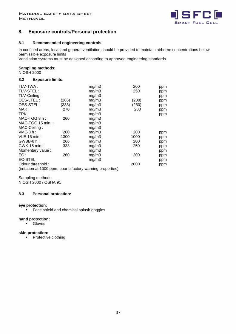
8. Exposure controls/Personal protection
8.1 Recommended engineering controls:
In confined areas, local and general ventilation should be provided to maintain airborne concentrations below permissible exposure limits Ventilation systems must be designed according to approved engineering standards Sampling methods: NIOSH 2000
8.2 Exposure limits:
TLV-TWA : mg/m3 200 ppm TLV-STEL : mg/m3 250 ppm TLV-Ceiling : mg/m3 ppm OES-LTEL : (266) mg/m3 (200) ppm OES-STEL : (333) mg/m3 (250) ppm MAK : 270 mg/m3 200 ppm TRK : mg/m3 ppm MAC-TGG 8 h : 260 mg/m3 MAC-TGG 15 min. : mg/m3 MAC-Ceiling : mg/m3 VME-8 h : 260 mg/m3 200 ppm VLE-15 min. : 1300 mg/m3 1000 ppm GWBB-8 h : 266 mg/m3 200 ppm GWK-15 min. : 333 mg/m3 250 ppm Momentary value : mg/m3 ppm EC : 260 mg/m3 200 ppm EC-STEL : mg/m3 ppm Odour threshold : 2000 ppm (irritation at 1000 ppm; poor olfactory warning properties) Sampling methods: NIOSH 2000 / OSHA 91
8.3 Personal protection:
eye protection:
Face shield and chemical splash goggles hand protection:
Gloves skin protection:
Protective clothing
Material safety data sheet Methanol
38
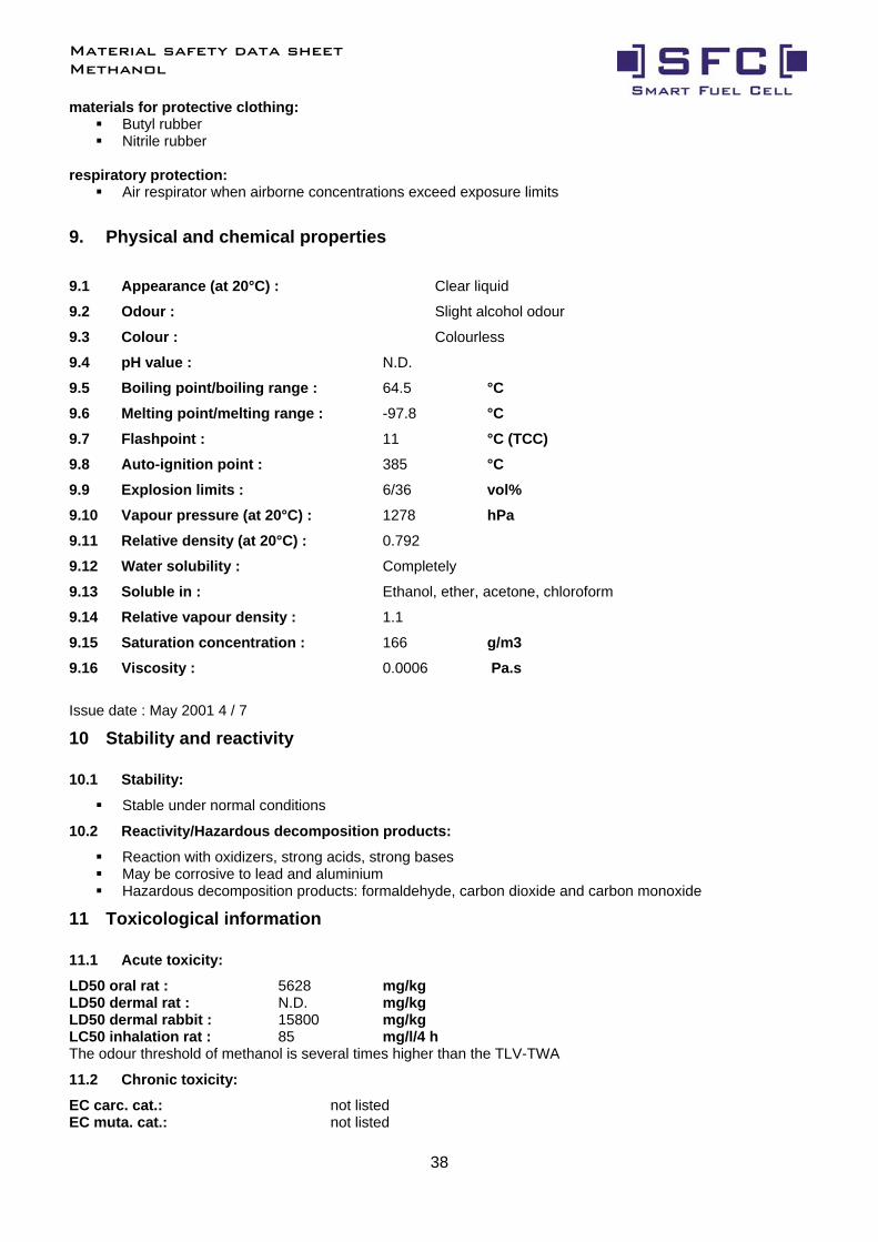
materials for protective clothing: Butyl rubber Nitrile rubber
respiratory protection:
Air respirator when airborne concentrations exceed exposure limits
9. Physical and chemical properties
9.1 Appearance (at 20°C) : Clear liquid
9.2 Odour : Slight alcohol odour
9.3 Colour : Colourless
9.4 pH value : N.D.
9.5 Boiling point/boiling range : 64.5 °C 9.6 Melting point/melting range : -97.8 °C
9.7 Flashpoint : 11 °C (TCC) 9.8 Auto-ignition point : 385 °C 9.9 Explosion limits : 6/36 vol% 9.10 Vapour pressure (at 20°C) : 1278 hPa 9.11 Relative density (at 20°C) : 0.792
9.12 Water solubility : Completely
9.13 Soluble in : Ethanol, ether, acetone, chloroform
9.14 Relative vapour density : 1.1
9.15 Saturation concentration : 166 g/m3 9.16 Viscosity : 0.0006 Pa.s
Issue date : May 2001 4 / 7
10 Stability and reactivity
10.1 Stability:
Stable under normal conditions
10.2 Reactivity/Hazardous decomposition products:
Reaction with oxidizers, strong acids, strong bases May be corrosive to lead and aluminium Hazardous decomposition products: formaldehyde, carbon dioxide and carbon monoxide
11 Toxicological information
11.1 Acute toxicity:
LD50 oral rat : 5628 mg/kg LD50 dermal rat : N.D. mg/kg LD50 dermal rabbit : 15800 mg/kg LC50 inhalation rat : 85 mg/l/4 h The odour threshold of methanol is several times higher than the TLV-TWA
11.2 Chronic toxicity:
EC carc. cat.: not listed EC muta. cat.: not listed
Material safety data sheet Methanol
39
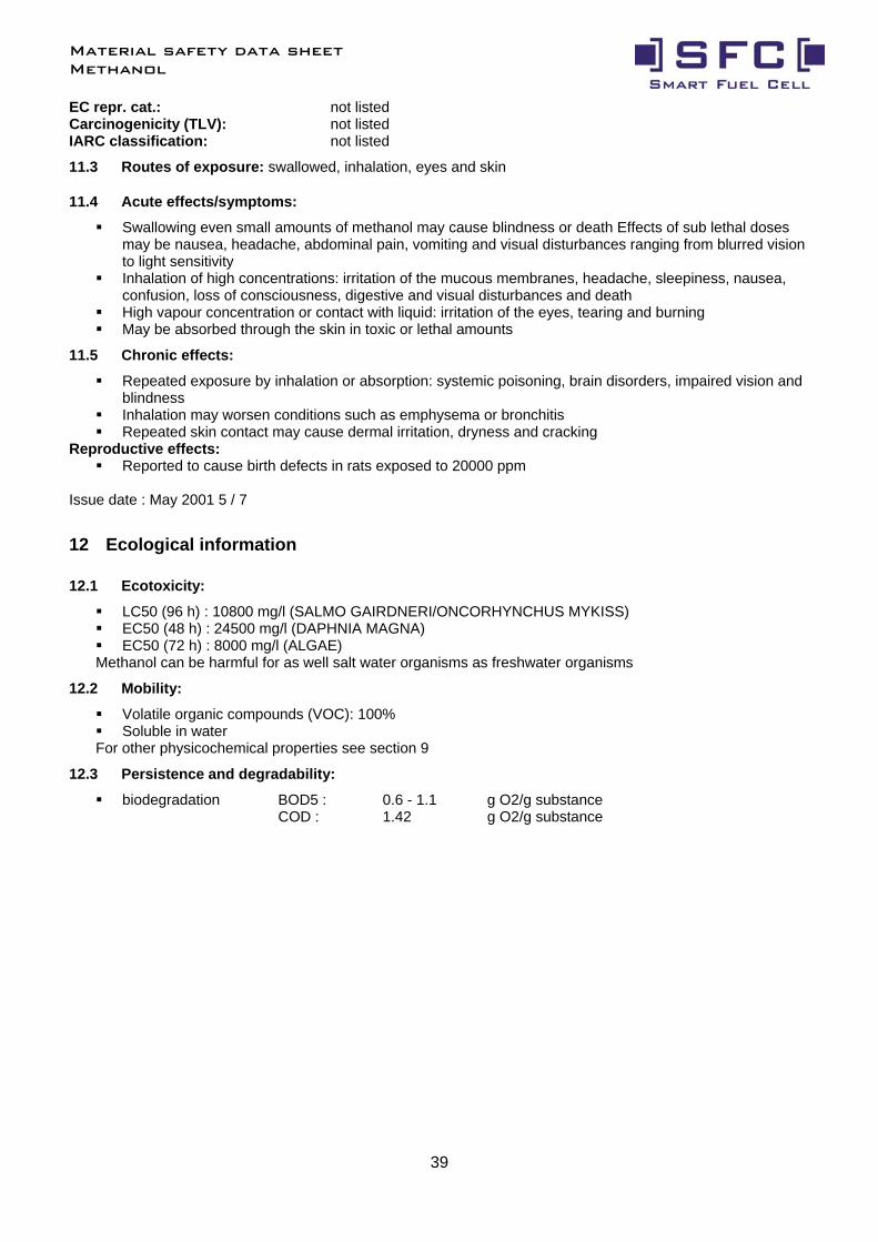
EC repr. cat.: not listed Carcinogenicity (TLV): not listed IARC classification: not listed
11.3 Routes of exposure: swallowed, inhalation, eyes and skin
11.4 Acute effects/symptoms:
Swallowing even small amounts of methanol may cause blindness or death Effects of sub lethal doses may be nausea, headache, abdominal pain, vomiting and visual disturbances ranging from blurred vision to light sensitivity
Inhalation of high concentrations: irritation of the mucous membranes, headache, sleepiness, nausea, confusion, loss of consciousness, digestive and visual disturbances and death
High vapour concentration or contact with liquid: irritation of the eyes, tearing and burning May be absorbed through the skin in toxic or lethal amounts
11.5 Chronic effects:
Repeated exposure by inhalation or absorption: systemic poisoning, brain disorders, impaired vision and blindness
Inhalation may worsen conditions such as emphysema or bronchitis Repeated skin contact may cause dermal irritation, dryness and cracking
Reproductive effects: Reported to cause birth defects in rats exposed to 20000 ppm
Issue date : May 2001 5 / 7
12 Ecological information
12.1 Ecotoxicity:
LC50 (96 h) : 10800 mg/l (SALMO GAIRDNERI/ONCORHYNCHUS MYKISS) EC50 (48 h) : 24500 mg/l (DAPHNIA MAGNA) EC50 (72 h) : 8000 mg/l (ALGAE)
Methanol can be harmful for as well salt water organisms as freshwater organisms
12.2 Mobility:
Volatile organic compounds (VOC): 100% Soluble in water
For other physicochemical properties see section 9
12.3 Persistence and degradability:
biodegradation BOD5 : 0.6 - 1.1 g O2/g substance COD : 1.42 g O2/g substance
Material safety data sheet Methanol
40
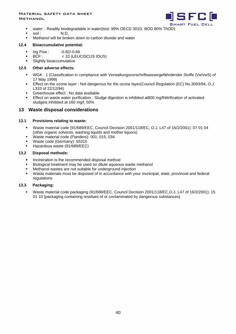
water : Readily biodegradable in water(test: 99% OECD 301D. BOD 80% ThOD) soil : N.D. Methanol will be broken down to carbon dioxide and water
12.4 Bioaccumulative potential:
log Pow : -0.82/-0.66 BCF : < 10 (LEUCISCUS IDUS) Slightly bioaccumulative
12.5 Other adverse effects:
WGK : 1 (Classification in compliance with Verwaltungsvorschriftwassergefährdender Stoffe (VwVwS) of 17 May 1999)
Effect on the ozone layer : Not dangerous for the ozone layer(Council Regulation (EC) No.3093/94, O.J. L333 of 22/12/94)
Greenhouse effect : No data available Effect on waste water purification : Sludge digestion is inhibited at800 mg/lNitrification of activated
sludgeis inhibited at 160 mg/l; 50%
13 Waste disposal considerations
13.1 Provisions relating to waste:
Waste material code (91/689/EEC, Council Decision 2001/118/EC, O.J. L47 of 16/2/2001): 07 01 04 (other organic solvents, washing liquids and mother liquors)
Waste material code (Flanders): 001; 015; 034 Waste code (Germany): 55315 Hazardous waste (91/689/EEC)
13.2 Disposal methods:
Incineration is the recommended disposal method Biological treatment may be used on dilute aqueous waste methanol Methanol wastes are not suitable for underground injection Waste materials must be disposed of in accordance with your municipal, state, provincial and federal
regulations
13.3 Packaging:
Waste material code packaging (91/689/EEC, Council Decision 2001/118/EC,O.J. L47 of 16/2/2001): 15 01 10 (packaging containing residues of or contaminated by dangerous substances)
Material safety data sheet Methanol
41
14 Transport information
336 1230
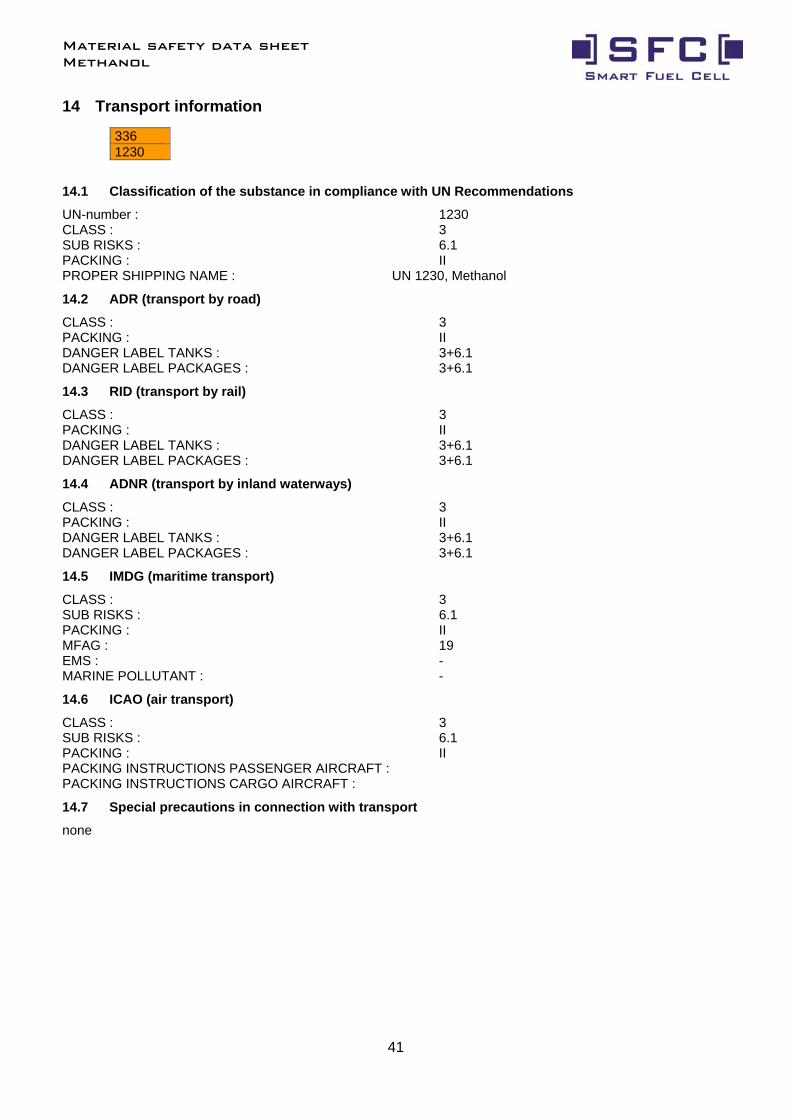
14.1 Classification of the substance in compliance with UN Recommendations
UN-number : 1230 CLASS : 3 SUB RISKS : 6.1 PACKING : II PROPER SHIPPING NAME : UN 1230, Methanol
14.2 ADR (transport by road)
CLASS : 3 PACKING : II DANGER LABEL TANKS : 3+6.1 DANGER LABEL PACKAGES : 3+6.1
14.3 RID (transport by rail)
CLASS : 3 PACKING : II DANGER LABEL TANKS : 3+6.1 DANGER LABEL PACKAGES : 3+6.1
14.4 ADNR (transport by inland waterways)
CLASS : 3 PACKING : II DANGER LABEL TANKS : 3+6.1 DANGER LABEL PACKAGES : 3+6.1
14.5 IMDG (maritime transport)
CLASS : 3 SUB RISKS : 6.1 PACKING : II MFAG : 19 EMS : - MARINE POLLUTANT : -
14.6 ICAO (air transport)
CLASS : 3 SUB RISKS : 6.1 PACKING : II PACKING INSTRUCTIONS PASSENGER AIRCRAFT : PACKING INSTRUCTIONS CARGO AIRCRAFT :
14.7 Special precautions in connection with transport
none
Material safety data sheet Methanol
42
14.8 Limited quantities (LQ)
When substances and their packaging meet the conditions established by ADR/RID/ADNR in chapter 3.4, only the following prescriptions shall be complied with: each package shall display a diamond-shaped figure with the following inscription:
‘UN 1230' or, in the case of different goods with different identification numbers within a single package:
the letters 'LQ'
15 Regulatory information
Enumerated in substance list Annex I of directive 67/548/EEC et sequens
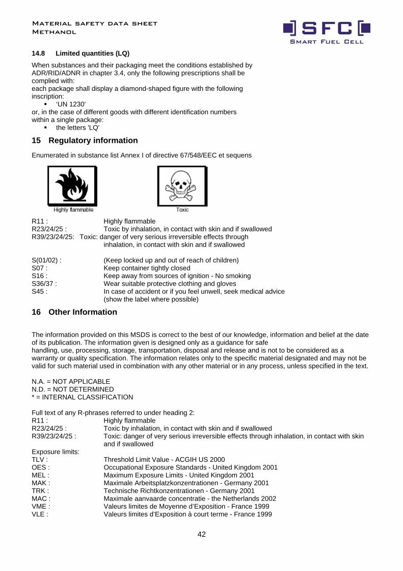
R11 : Highly flammable R23/24/25 : Toxic by inhalation, in contact with skin and if swallowed R39/23/24/25: Toxic: danger of very serious irreversible effects through
inhalation, in contact with skin and if swallowed S(01/02) : (Keep locked up and out of reach of children) S07 : Keep container tightly closed S16 : Keep away from sources of ignition - No smoking S36/37 : Wear suitable protective clothing and gloves S45 : In case of accident or if you feel unwell, seek medical advice
(show the label where possible)
16 Other Information
The information provided on this MSDS is correct to the best of our knowledge, information and belief at the date of its publication. The information given is designed only as a guidance for safe handling, use, processing, storage, transportation, disposal and release and is not to be considered as a warranty or quality specification. The information relates only to the specific material designated and may not be valid for such material used in combination with any other material or in any process, unless specified in the text. N.A. = NOT APPLICABLE N.D. = NOT DETERMINED * = INTERNAL CLASSIFICATION Full text of any R-phrases referred to under heading 2: R11 : Highly flammable R23/24/25 : Toxic by inhalation, in contact with skin and if swallowed R39/23/24/25 : Toxic: danger of very serious irreversible effects through inhalation, in contact with skin
and if swallowed Exposure limits: TLV : Threshold Limit Value - ACGIH US 2000 OES : Occupational Exposure Standards - United Kingdom 2001 MEL : Maximum Exposure Limits - United Kingdom 2001 MAK : Maximale Arbeitsplatzkonzentrationen - Germany 2001 TRK : Technische Richtkonzentrationen - Germany 2001 MAC : Maximale aanvaarde concentratie - the Netherlands 2002 VME : Valeurs limites de Moyenne d’Exposition - France 1999 VLE : Valeurs limites d’Exposition à court terme - France 1999

Material safety data sheet Methanol
43
GWBB : Grenswaarde beroepsmatige blootstelling - Belgium 1998 GWK : Grenswaarde kortstondige blootstelling - Belgium 1998 EC : Indicative occupational exposure limit values - directive 2000/39/EC NOTE TO PHYSICIAN Acute exposure to methanol, either through ingestion or breathing high airborne concentrations can result in symptoms appearing between 40 minutes and 72 hours after exposure. Symptoms and signs are usually limited to CNS, eyes and gastrointestinal tract. Because of the initial CNS's effects of headache, vertigo, lethargy and confusion, there may be an impression of ethanol intoxication. Blurred vision, decreased acuity and photophobia are common complaints. Treatment with ipecac or lavage is indicated in any patient presenting the symptoms within two hours of ingestion. A profound metabolic acidosis occurs in severe poisoning and serum bicarbonate levels are a more accurate measure of severity than serum methanol levels. Treatment protocols are available from most major hospitals and early collaboration with appropriate hospitals is recommended.
SFC Smart Fuel Cell AG Eugen-Saenger-Ring 4 D-85649 Brunnthal-Nord, Germany Hotline: +49 89 607 454-99
www.smartfuelcell.com
All rights reserved. Subject to availability. Rights of modification reserved.
Operating manual Status: 06/2005 Art.Nr.: 150 901 010
System Data Model: SFC A50 Art. #: 150 00 0 001 Serial #.: 50 _ _ _ _ _ _ - _ _ _ _