Embed Size (px)
Citation preview
ww
w.l
ight
war
e.co
.za
•
i
nfo@
light
war
e.co
.za
SF33
SF33Multi-beam laser sensor Product manual
SF33 Multi-beam sensor - Product Manual - Revision 2 of © LightWare Optoelectronics (Pty) Ltd, 20161 15
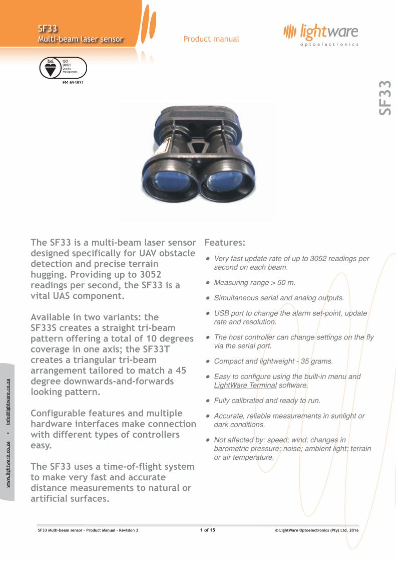
The SF33 is a multi-beam laser sensor designed specifically for UAV obstacle detection and precise terrain hugging. Providing up to 3052 readings per second, the SF33 is a vital UAS component.
Available in two variants: the SF33S creates a straight tri-beam pattern offering a total of 10 degrees coverage in one axis; the SF33T creates a triangular tri-beam arrangement tailored to match a 45 degree downwards-and-forwards looking pattern.
Configurable features and multiple hardware interfaces make connection with different types of controllers easy.
The SF33 uses a time-of-flight system to make very fast and accurate distance measurements to natural or artificial surfaces.
Features:
• Very fast update rate of up to 3052 readings per second on each beam.
• Measuring range > 50 m.
• Simultaneous serial and analog outputs.
• USB port to change the alarm set-point, update rate and resolution.
• The host controller can change settings on the fly via the serial port.
• Compact and lightweight - 35 grams.
• Easy to configure using the built-in menu and LightWare Terminal software.
• Fully calibrated and ready to run.
• Accurate, reliable measurements in sunlight or dark conditions.
• Not affected by: speed; wind; changes in barometric pressure; noise; ambient light; terrain or air temperature.
ww
w.l
ight
war
e.co
.za
•
i
nfo@
light
war
e.co
.za
SF33
SF33Multi-beam laser sensor Product manual
Table of contents
Table of figures
Figure 1 :: The main features of the SF33 3 ...............................................................................................................Figure 2 :: LightWare Terminal showing menu options 4 ................................................................................................Figure 3 :: Power from the USB port 6.....................................................................................................................Figure 4 :: Regulated +5 V DC power supply connections 6.............................................................................................Figure 5 :: USB communications 7..........................................................................................................................Figure 6 :: Analog voltage connections 8...................................................................................................................Figure 7 :: Serial interface connections 6 ..................................................................................................................Figure 8 :: Digital interface connections 6 .................................................................................................................Figure 9 :: LightWare Terminal showing menu options 7 ................................................................................................Figure 10 :: Altitude represented by distance (Serial / I2C) and analog voltage 8 ..................................................................Figure 11 :: Labelling on the SF33 9 ........................................................................................................................Figure 12 :: Dimension drawings of the SF33 10 ..........................................................................................................
Product ordering codes
Disclaimer
Information found in this document is used entirely at the reader’s own risk and whilst every effort has been made to ensure its validity neither LightWare Optoelectronics (Pty) Ltd nor its representatives make any warranties with respect the accuracy of the information contained herein.
Product ordering codes 2 .....................................................................................................................................1. Overview 3 ...................................................................................................................................................2. Quick start guide 4 ..........................................................................................................................................3. Powering up the SF33 6 ....................................................................................................................................4. Communicating with the USB port 7 .....................................................................................................................5. System configuration 7 .....................................................................................................................................6. Communicating with the serial port 8 ...................................................................................................................7. The analog voltage interface 11 ..........................................................................................................................8. The alarm interface 12 .....................................................................................................................................9. USB port settings 12 ........................................................................................................................................10. Instructions for safe use 13 ..............................................................................................................................Appendix A :: Specifications 14 ..............................................................................................................................Appendix B :: Dimensions 14 .................................................................................................................................Appendix C :: Main cable type 1, 35 cm 15 .................................................................................................................Revision history 15..............................................................................................................................................
Model family Model name Model description
SF33 SF33S/B (50 m) Multi-beam laser sensor, straight beam pattern, max 50 m
SF33 SF33T/B (50 m) Multi-beam laser sensor, triangular beam pattern, max 50 m
SF33 Multi-beam sensor - Product Manual - Revision 2 of © LightWare Optoelectronics (Pty) Ltd, 20162 15
ww
w.l
ight
war
e.co
.za
•
i
nfo@
light
war
e.co
.za
SF33
SF33Multi-beam laser sensor Product manual
1. Overview
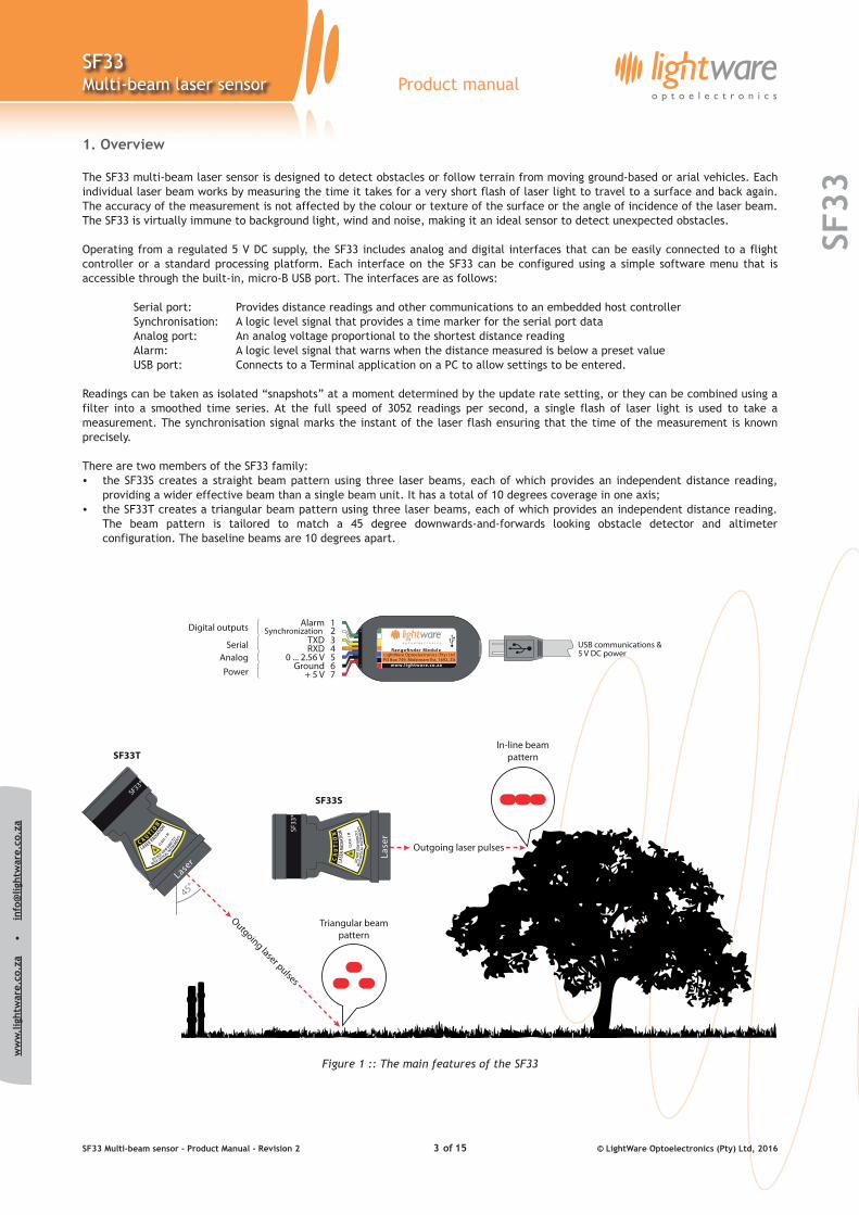
The SF33 multi-beam laser sensor is designed to detect obstacles or follow terrain from moving ground-based or arial vehicles. Each individual laser beam works by measuring the time it takes for a very short flash of laser light to travel to a surface and back again. The accuracy of the measurement is not affected by the colour or texture of the surface or the angle of incidence of the laser beam. The SF33 is virtually immune to background light, wind and noise, making it an ideal sensor to detect unexpected obstacles.
Operating from a regulated 5 V DC supply, the SF33 includes analog and digital interfaces that can be easily connected to a flight controller or a standard processing platform. Each interface on the SF33 can be configured using a simple software menu that is accessible through the built-in, micro-B USB port. The interfaces are as follows:
Serial port: Provides distance readings and other communications to an embedded host controller Synchronisation: A logic level signal that provides a time marker for the serial port data Analog port: An analog voltage proportional to the shortest distance reading Alarm: A logic level signal that warns when the distance measured is below a preset value USB port: Connects to a Terminal application on a PC to allow settings to be entered.
Readings can be taken as isolated “snapshots” at a moment determined by the update rate setting, or they can be combined using a filter into a smoothed time series. At the full speed of 3052 readings per second, a single flash of laser light is used to take a measurement. The synchronisation signal marks the instant of the laser flash ensuring that the time of the measurement is known precisely.
There are two members of the SF33 family: • the SF33S creates a straight beam pattern using three laser beams, each of which provides an independent distance reading,
providing a wider effective beam than a single beam unit. It has a total of 10 degrees coverage in one axis;• the SF33T creates a triangular beam pattern using three laser beams, each of which provides an independent distance reading.
The beam pattern is tailored to match a 45 degree downwards-and-forwards looking obstacle detector and altimeter configuration. The baseline beams are 10 degrees apart.
Figure 1 :: The main features of the SF33
SF33 Multi-beam sensor - Product Manual - Revision 2 of © LightWare Optoelectronics (Pty) Ltd, 20163 15
ww
w.l
ight
war
e.co
.za
•
i
nfo@
light
war
e.co
.za
SF33
SF33Multi-beam laser sensor Product manual
2. Quick start guide
1. CAUTION - The SF33 laser rangefinder contains a laser and should never be aimed at a person or an animal. Do not look at the beam directly with optical instruments.
2. Download LightWare Terminal software from www.lightware.co.za > Library > Documents > Software onto your PC. Open the installer package and follow the installation instructions. Everything needed for communicating with SF33 will automatically be installed.
3. Plug the “micro-B to type A” USB cable provided into the SF33’s micro USB connector and connect the other end to yourPC. This provides both power and communication to the unit.
4. Start the LightWare Terminal software and click the “Connect” icon to open a communications port.
5. If the connection isn’t made automatically, click the “Laser” icon and select the correct USB port from the list shown.
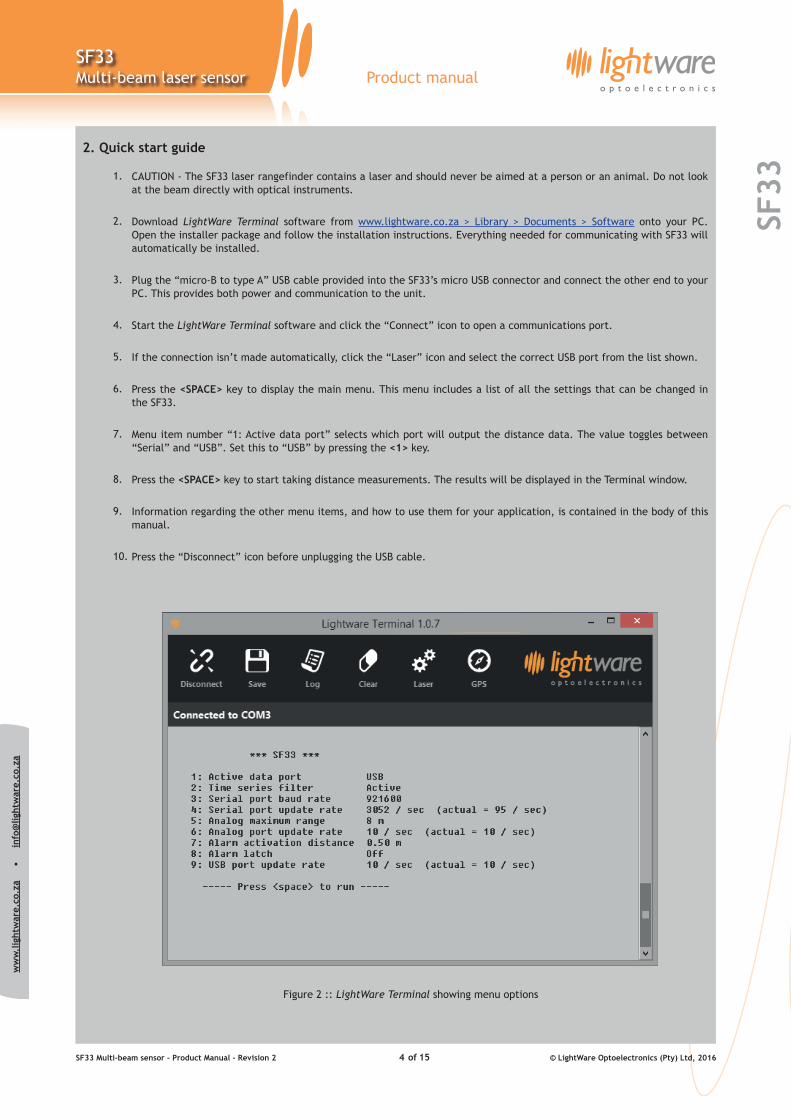
6. Press the <SPACE> key to display the main menu. This menu includes a list of all the settings that can be changed in the SF33.
7. Menu item number “1: Active data port” selects which port will output the distance data. The value toggles between “Serial” and “USB”. Set this to “USB” by pressing the <1> key.
8. Press the <SPACE> key to start taking distance measurements. The results will be displayed in the Terminal window.
9. Information regarding the other menu items, and how to use them for your application, is contained in the body of this manual.
10. Press the “Disconnect” icon before unplugging the USB cable.
Figure 2 :: LightWare Terminal showing menu options
SF33 Multi-beam sensor - Product Manual - Revision 2 of © LightWare Optoelectronics (Pty) Ltd, 20164 15
ww
w.l
ight
war
e.co
.za
•
i
nfo@
light
war
e.co
.za
SF33
SF33Multi-beam laser sensor Product manual
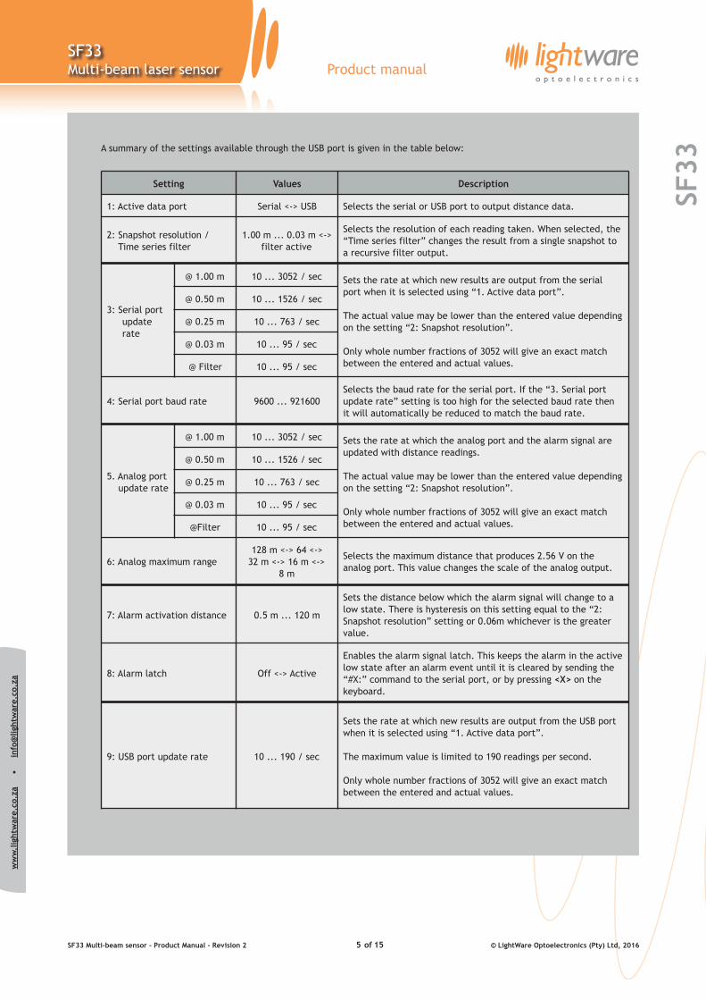
A summary of the settings available through the USB port is given in the table below:
Setting Values Description
1: Active data port Serial <-> USB Selects the serial or USB port to output distance data.
2: Snapshot resolution / Time series filter
1.00 m ... 0.03 m <->filter active
Selects the resolution of each reading taken. When selected, the “Time series filter” changes the result from a single snapshot to a recursive filter output.
3: Serial port update rate
@ 1.00 m 10 ... 3052 / sec Sets the rate at which new results are output from the serial port when it is selected using “1. Active data port”.
The actual value may be lower than the entered value depending on the setting “2: Snapshot resolution”.
Only whole number fractions of 3052 will give an exact match between the entered and actual values.
@ 0.50 m 10 ... 1526 / sec
@ 0.25 m 10 ... 763 / sec
@ 0.03 m 10 ... 95 / sec
@ Filter 10 ... 95 / sec
4: Serial port baud rate 9600 ... 921600Selects the baud rate for the serial port. If the “3. Serial port update rate” setting is too high for the selected baud rate then it will automatically be reduced to match the baud rate.
5. Analog port update rate
@ 1.00 m 10 ... 3052 / sec Sets the rate at which the analog port and the alarm signal are updated with distance readings.
The actual value may be lower than the entered value depending on the setting “2: Snapshot resolution”.
Only whole number fractions of 3052 will give an exact match between the entered and actual values.
@ 0.50 m 10 ... 1526 / sec
@ 0.25 m 10 ... 763 / sec
@ 0.03 m 10 ... 95 / sec
@Filter 10 ... 95 / sec
6: Analog maximum range128 m <-> 64 <->
32 m <-> 16 m <-> 8 m
Selects the maximum distance that produces 2.56 V on the analog port. This value changes the scale of the analog output.
7: Alarm activation distance 0.5 m ... 120 m
Sets the distance below which the alarm signal will change to a low state. There is hysteresis on this setting equal to the “2: Snapshot resolution” setting or 0.06m whichever is the greater value.
8: Alarm latch Off <-> Active
Enables the alarm signal latch. This keeps the alarm in the active low state after an alarm event until it is cleared by sending the “#X:” command to the serial port, or by pressing <X> on the keyboard.
9: USB port update rate 10 ... 190 / sec
Sets the rate at which new results are output from the USB port when it is selected using “1. Active data port”.
The maximum value is limited to 190 readings per second.
Only whole number fractions of 3052 will give an exact match between the entered and actual values.
SF33 Multi-beam sensor - Product Manual - Revision 2 of © LightWare Optoelectronics (Pty) Ltd, 20165 15
ww
w.l
ight
war
e.co
.za
•
i
nfo@
light
war
e.co
.za
SF33
SF33Multi-beam laser sensor Product manual
3. Powering up the SF33
The SF33 gets power from either a regulated +5 V DC supply on the main connector or via the USB port when it is connected to a PC. There are a number of digital and analog interfaces on the main connector and either one or a combination of interfaces may be connected to a host controller. The built-in micro-B USB port can be used to input settings and to test the performance of the SF33.
Power supply option 1: USB
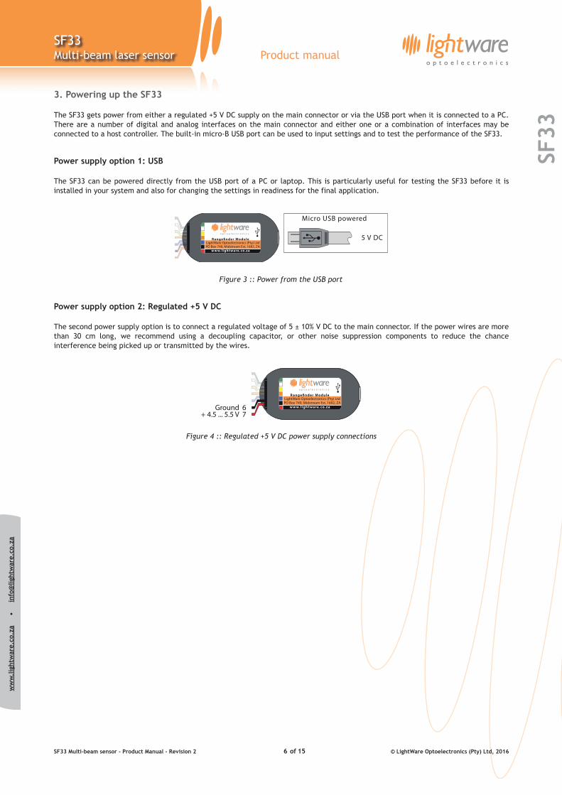
The SF33 can be powered directly from the USB port of a PC or laptop. This is particularly useful for testing the SF33 before it is installed in your system and also for changing the settings in readiness for the final application.
Figure 3 :: Power from the USB port
Power supply option 2: Regulated +5 V DC
The second power supply option is to connect a regulated voltage of 5 ± 10% V DC to the main connector. If the power wires are more than 30 cm long, we recommend using a decoupling capacitor, or other noise suppression components to reduce the chance interference being picked up or transmitted by the wires.
Figure 4 :: Regulated +5 V DC power supply connections
SF33 Multi-beam sensor - Product Manual - Revision 2 of © LightWare Optoelectronics (Pty) Ltd, 20166 15
ww
w.l
ight
war
e.co
.za
•
i
nfo@
light
war
e.co
.za
SF33
SF33Multi-beam laser sensor Product manual
4. Communicating with the USB port
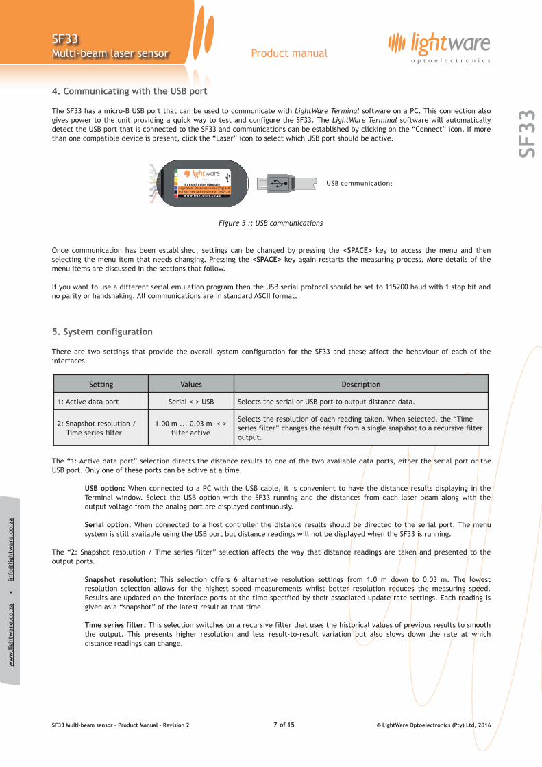
The SF33 has a micro-B USB port that can be used to communicate with LightWare Terminal software on a PC. This connection also gives power to the unit providing a quick way to test and configure the SF33. The LightWare Terminal software will automatically detect the USB port that is connected to the SF33 and communications can be established by clicking on the “Connect” icon. If more than one compatible device is present, click the “Laser” icon to select which USB port should be active.
Figure 5 :: USB communications
Once communication has been established, settings can be changed by pressing the <SPACE> key to access the menu and then selecting the menu item that needs changing. Pressing the <SPACE> key again restarts the measuring process. More details of the menu items are discussed in the sections that follow.
If you want to use a different serial emulation program then the USB serial protocol should be set to 115200 baud with 1 stop bit and no parity or handshaking. All communications are in standard ASCII format.
5. System configuration
There are two settings that provide the overall system configuration for the SF33 and these affect the behaviour of each of the interfaces.
The “1: Active data port” selection directs the distance results to one of the two available data ports, either the serial port or the USB port. Only one of these ports can be active at a time.
USB option: When connected to a PC with the USB cable, it is convenient to have the distance results displaying in the Terminal window. Select the USB option with the SF33 running and the distances from each laser beam along with the output voltage from the analog port are displayed continuously.
Serial option: When connected to a host controller the distance results should be directed to the serial port. The menu system is still available using the USB port but distance readings will not be displayed when the SF33 is running.
The “2: Snapshot resolution / Time series filter” selection affects the way that distance readings are taken and presented to the output ports.
Snapshot resolution: This selection offers 6 alternative resolution settings from 1.0 m down to 0.03 m. The lowest resolution selection allows for the highest speed measurements whilst better resolution reduces the measuring speed. Results are updated on the interface ports at the time specified by their associated update rate settings. Each reading is given as a “snapshot” of the latest result at that time.
Time series filter: This selection switches on a recursive filter that uses the historical values of previous results to smooth the output. This presents higher resolution and less result-to-result variation but also slows down the rate at which distance readings can change.
Setting Values Description
1: Active data port Serial <-> USB Selects the serial or USB port to output distance data.
2: Snapshot resolution / Time series filter
1.00 m ... 0.03 m <-> filter active
Selects the resolution of each reading taken. When selected, the “Time series filter” changes the result from a single snapshot to a recursive filter output.
SF33 Multi-beam sensor - Product Manual - Revision 2 of © LightWare Optoelectronics (Pty) Ltd, 20167 15
ww
w.l
ight
war
e.co
.za
•
i
nfo@
light
war
e.co
.za
SF33
SF33Multi-beam laser sensor Product manual
6. Communicating with the serial port
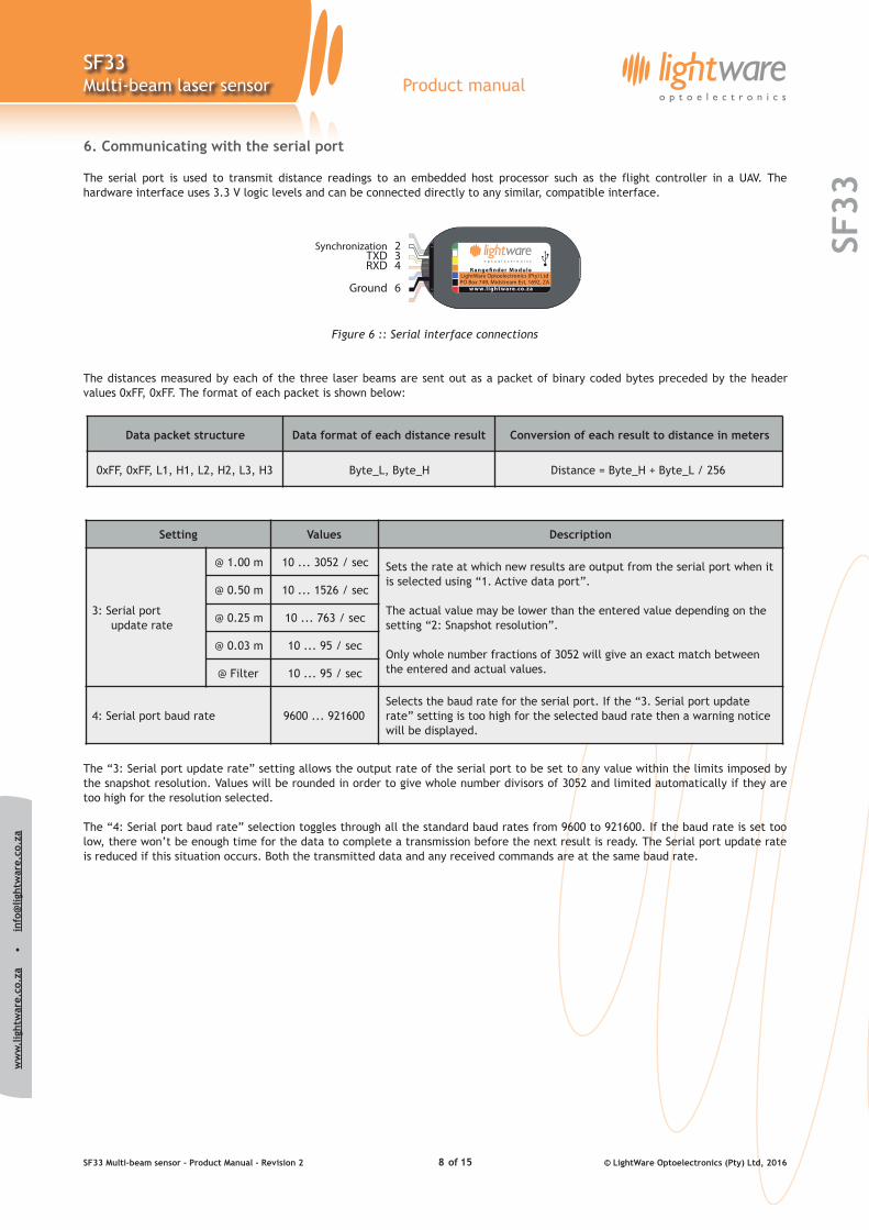
The serial port is used to transmit distance readings to an embedded host processor such as the flight controller in a UAV. The hardware interface uses 3.3 V logic levels and can be connected directly to any similar, compatible interface.
Figure 6 :: Serial interface connections
The distances measured by each of the three laser beams are sent out as a packet of binary coded bytes preceded by the header values 0xFF, 0xFF. The format of each packet is shown below:
The “3: Serial port update rate” setting allows the output rate of the serial port to be set to any value within the limits imposed by the snapshot resolution. Values will be rounded in order to give whole number divisors of 3052 and limited automatically if they are too high for the resolution selected.
The “4: Serial port baud rate” selection toggles through all the standard baud rates from 9600 to 921600. If the baud rate is set too low, there won’t be enough time for the data to complete a transmission before the next result is ready. The Serial port update rate is reduced if this situation occurs. Both the transmitted data and any received commands are at the same baud rate.
Data packet structure Data format of each distance result Conversion of each result to distance in meters
0xFF, 0xFF, L1, H1, L2, H2, L3, H3 Byte_L, Byte_H Distance = Byte_H + Byte_L / 256
Setting Values Description
3: Serial port update rate
@ 1.00 m 10 ... 3052 / sec Sets the rate at which new results are output from the serial port when it is selected using “1. Active data port”.
The actual value may be lower than the entered value depending on the setting “2: Snapshot resolution”.
Only whole number fractions of 3052 will give an exact match between the entered and actual values.
@ 0.50 m 10 ... 1526 / sec
@ 0.25 m 10 ... 763 / sec
@ 0.03 m 10 ... 95 / sec
@ Filter 10 ... 95 / sec
4: Serial port baud rate 9600 ... 921600Selects the baud rate for the serial port. If the “3. Serial port update rate” setting is too high for the selected baud rate then a warning notice will be displayed.
SF33 Multi-beam sensor - Product Manual - Revision 2 of © LightWare Optoelectronics (Pty) Ltd, 20168 15
ww
w.l
ight
war
e.co
.za
•
i
nfo@
light
war
e.co
.za
SF33
SF33Multi-beam laser sensor Product manual
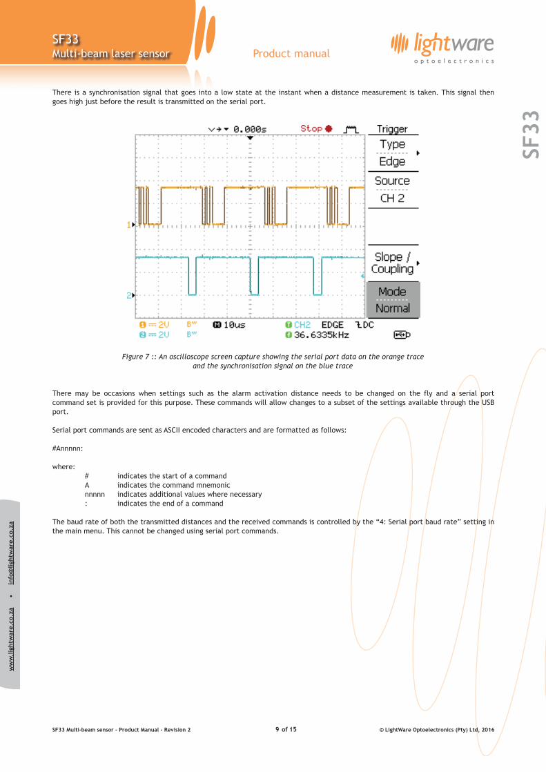
There is a synchronisation signal that goes into a low state at the instant when a distance measurement is taken. This signal then goes high just before the result is transmitted on the serial port.
Figure 7 :: An oscilloscope screen capture showing the serial port data on the orange trace and the synchronisation signal on the blue trace
There may be occasions when settings such as the alarm activation distance needs to be changed on the fly and a serial port command set is provided for this purpose. These commands will allow changes to a subset of the settings available through the USB port.
Serial port commands are sent as ASCII encoded characters and are formatted as follows:
#Annnnn:
where: # indicates the start of a command A indicates the command mnemonic nnnnn indicates additional values where necessary : indicates the end of a command
The baud rate of both the transmitted distances and the received commands is controlled by the “4: Serial port baud rate” setting in the main menu. This cannot be changed using serial port commands.
SF33 Multi-beam sensor - Product Manual - Revision 2 of © LightWare Optoelectronics (Pty) Ltd, 20169 15
ww
w.l
ight
war
e.co
.za
•
i
nfo@
light
war
e.co
.za
SF33
SF33Multi-beam laser sensor Product manual
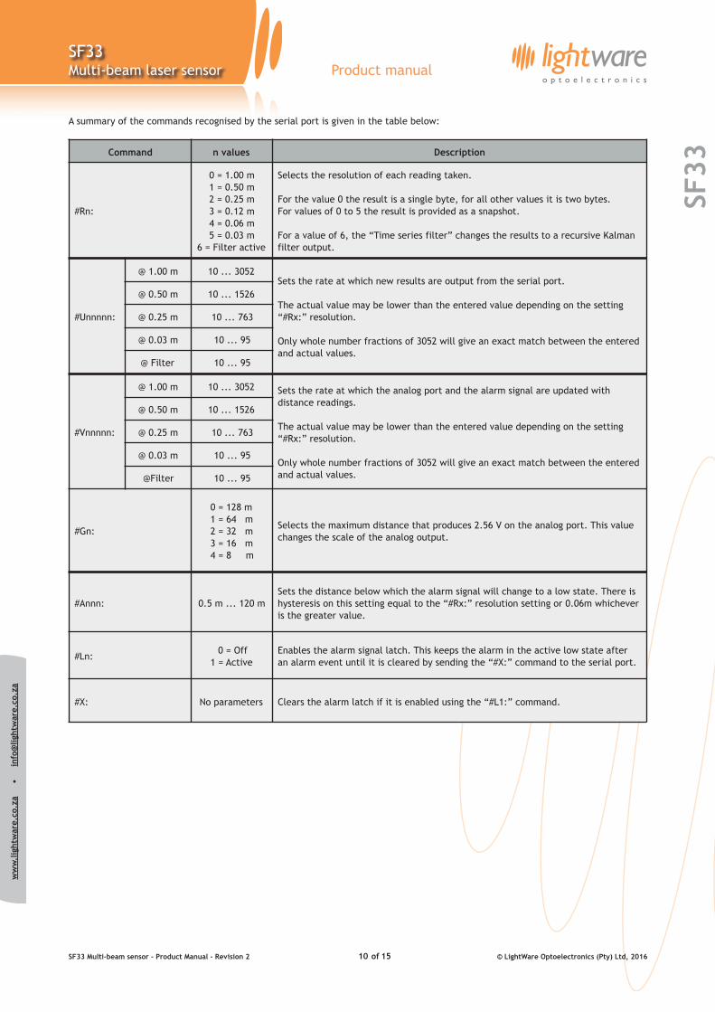
A summary of the commands recognised by the serial port is given in the table below:
Command n values Description
#Rn:
0 = 1.00 m 1 = 0.50 m 2 = 0.25 m 3 = 0.12 m 4 = 0.06 m 5 = 0.03 m
6 = Filter active
Selects the resolution of each reading taken.
For the value 0 the result is a single byte, for all other values it is two bytes. For values of 0 to 5 the result is provided as a snapshot.
For a value of 6, the “Time series filter” changes the results to a recursive Kalman filter output.
#Unnnnn:
@ 1.00 m 10 ... 3052Sets the rate at which new results are output from the serial port.
The actual value may be lower than the entered value depending on the setting “#Rx:” resolution.
Only whole number fractions of 3052 will give an exact match between the entered and actual values.
@ 0.50 m 10 ... 1526
@ 0.25 m 10 ... 763
@ 0.03 m 10 ... 95
@ Filter 10 ... 95
#Vnnnnn:
@ 1.00 m 10 ... 3052 Sets the rate at which the analog port and the alarm signal are updated with distance readings.
The actual value may be lower than the entered value depending on the setting “#Rx:” resolution.
Only whole number fractions of 3052 will give an exact match between the entered and actual values.
@ 0.50 m 10 ... 1526
@ 0.25 m 10 ... 763
@ 0.03 m 10 ... 95
@Filter 10 ... 95
#Gn:
0 = 128 m 1 = 64 m 2 = 32 m 3 = 16 m 4 = 8 m
Selects the maximum distance that produces 2.56 V on the analog port. This value changes the scale of the analog output.
#Annn: 0.5 m ... 120 mSets the distance below which the alarm signal will change to a low state. There is hysteresis on this setting equal to the “#Rx:” resolution setting or 0.06m whichever is the greater value.
#Ln: 0 = Off
1 = ActiveEnables the alarm signal latch. This keeps the alarm in the active low state after an alarm event until it is cleared by sending the “#X:” command to the serial port.
#X: No parameters Clears the alarm latch if it is enabled using the “#L1:” command.
SF33 Multi-beam sensor - Product Manual - Revision 2 of © LightWare Optoelectronics (Pty) Ltd, 201610 15
ww
w.l
ight
war
e.co
.za
•
i
nfo@
light
war
e.co
.za
SF33
SF33Multi-beam laser sensor Product manual
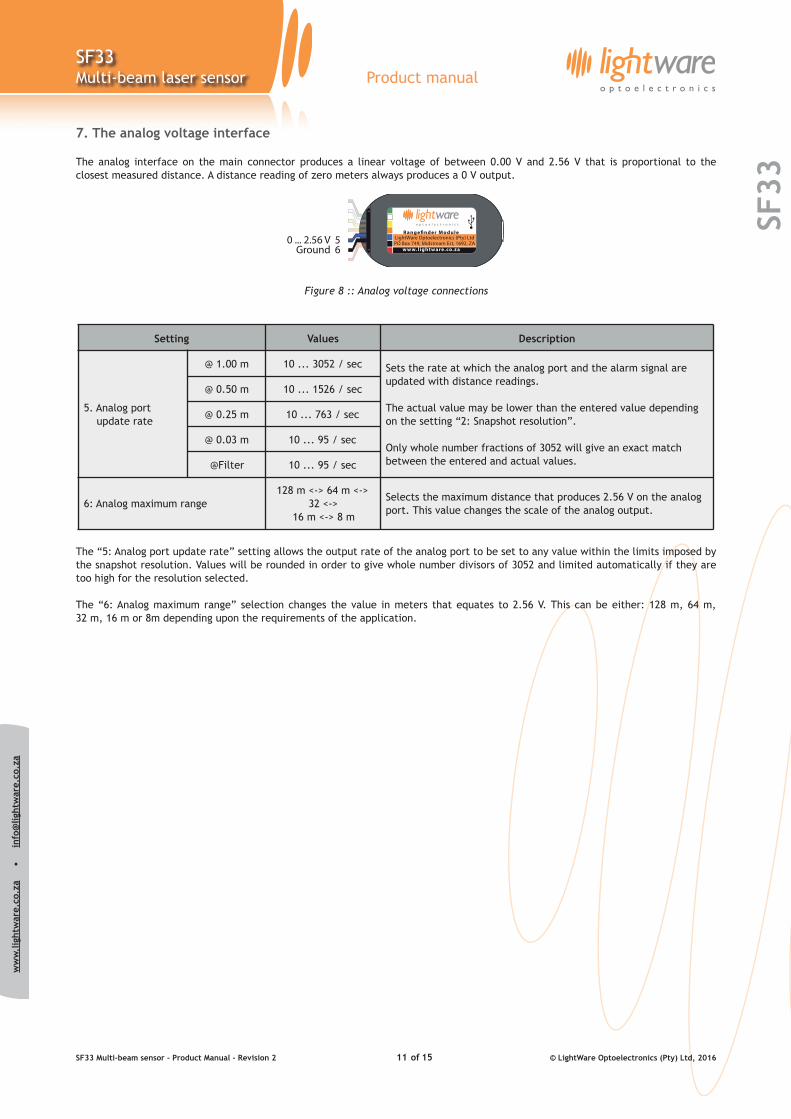
7. The analog voltage interface
The analog interface on the main connector produces a linear voltage of between 0.00 V and 2.56 V that is proportional to the closest measured distance. A distance reading of zero meters always produces a 0 V output.
Figure 8 :: Analog voltage connections
The “5: Analog port update rate” setting allows the output rate of the analog port to be set to any value within the limits imposed by the snapshot resolution. Values will be rounded in order to give whole number divisors of 3052 and limited automatically if they are too high for the resolution selected.
The “6: Analog maximum range” selection changes the value in meters that equates to 2.56 V. This can be either: 128 m, 64 m, 32 m, 16 m or 8m depending upon the requirements of the application.
Setting Values Description
5. Analog port update rate
@ 1.00 m 10 ... 3052 / sec Sets the rate at which the analog port and the alarm signal are updated with distance readings.
The actual value may be lower than the entered value depending on the setting “2: Snapshot resolution”.
Only whole number fractions of 3052 will give an exact match between the entered and actual values.
@ 0.50 m 10 ... 1526 / sec
@ 0.25 m 10 ... 763 / sec
@ 0.03 m 10 ... 95 / sec
@Filter 10 ... 95 / sec
6: Analog maximum range128 m <-> 64 m <->
32 <-> 16 m <-> 8 m
Selects the maximum distance that produces 2.56 V on the analog port. This value changes the scale of the analog output.
SF33 Multi-beam sensor - Product Manual - Revision 2 of © LightWare Optoelectronics (Pty) Ltd, 201611 15
ww
w.l
ight
war
e.co
.za
•
i
nfo@
light
war
e.co
.za
SF33
SF33Multi-beam laser sensor Product manual
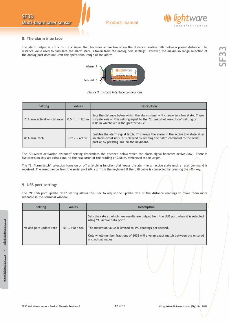
8. The alarm interface
The alarm output is a 0 V to 3.3 V signal that becomes active low when the distance reading falls below a preset distance. The distance value used to calculate the alarm state is taken from the analog port settings. However, the maximum range selection of the analog port does not limit the operational range of the alarm.
Figure 9 :: Alarm interface connections
The “7: Alarm activation distance” setting determines the distance below which the alarm signal becomes active (low). There is hysteresis on this set point equal to the resolution of the reading or 0.06 m, whichever is the larger.
The “8: Alarm latch” selection turns on or off a latching function that keeps the alarm in an active state until a reset command is received. The reset can be from the serial port (#X:) or from the keyboard if the USB cable is connected by pressing the <X> key.
9. USB port settings
The “9: USB port update rate” setting allows the user to adjust the update rate of the distance readings to make them more readable in the Terminal window.
Setting Values Description
7: Alarm activation distance 0.5 m ... 120 mSets the distance below which the alarm signal will change to a low state. There is hysteresis on this setting equal to the “2: Snapshot resolution” setting or 0.06 m whichever is the greater value.
8: Alarm latch Off <-> ActiveEnables the alarm signal latch. This keeps the alarm in the active low state after an alarm event until it is cleared by sending the “#X:” command to the serial port or by pressing <X> on the keyboard.
Setting Values Description
9: USB port update rate 10 ... 190 / sec
Sets the rate at which new results are output from the USB port when it is selected using “1. Active data port”.
The maximum value is limited to 190 readings per second.
Only whole number fractions of 3052 will give an exact match between the entered and actual values.
SF33 Multi-beam sensor - Product Manual - Revision 2 of © LightWare Optoelectronics (Pty) Ltd, 201612 15
ww
w.l
ight
war
e.co
.za
•
i
nfo@
light
war
e.co
.za
SF33
SF33Multi-beam laser sensor Product manual
10. Instructions for safe use
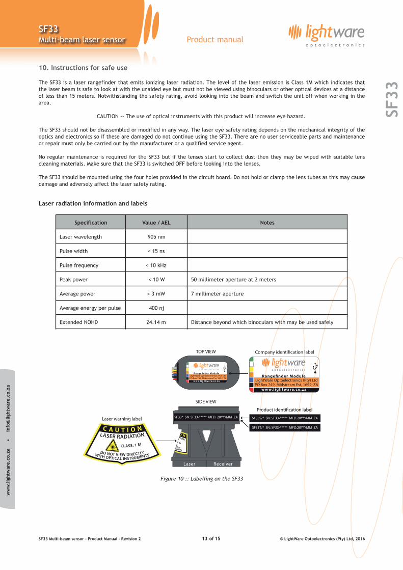
The SF33 is a laser rangefinder that emits ionizing laser radiation. The level of the laser emission is Class 1M which indicates that the laser beam is safe to look at with the unaided eye but must not be viewed using binoculars or other optical devices at a distance of less than 15 meters. Notwithstanding the safety rating, avoid looking into the beam and switch the unit off when working in the area.
CAUTION -- The use of optical instruments with this product will increase eye hazard.
The SF33 should not be disassembled or modified in any way. The laser eye safety rating depends on the mechanical integrity of the optics and electronics so if these are damaged do not continue using the SF33. There are no user serviceable parts and maintenance or repair must only be carried out by the manufacturer or a qualified service agent.
No regular maintenance is required for the SF33 but if the lenses start to collect dust then they may be wiped with suitable lens cleaning materials. Make sure that the SF33 is switched OFF before looking into the lenses.
The SF33 should be mounted using the four holes provided in the circuit board. Do not hold or clamp the lens tubes as this may cause damage and adversely affect the laser safety rating.
Laser radiation information and labels
Figure 10 :: Labelling on the SF33
Specification Value / AEL Notes
Laser wavelength 905 nm
Pulse width < 15 ns
Pulse frequency < 10 kHz
Peak power < 10 W 50 millimeter aperture at 2 meters
Average power < 3 mW 7 millimeter aperture
Average energy per pulse 400 nj
Extended NOHD 24.14 m Distance beyond which binoculars with may be used safely
SF33 Multi-beam sensor - Product Manual - Revision 2 of © LightWare Optoelectronics (Pty) Ltd, 201613 15
ww
w.l
ight
war
e.co
.za
•
i
nfo@
light
war
e.co
.za
SF33
SF33Multi-beam laser sensor Product manual
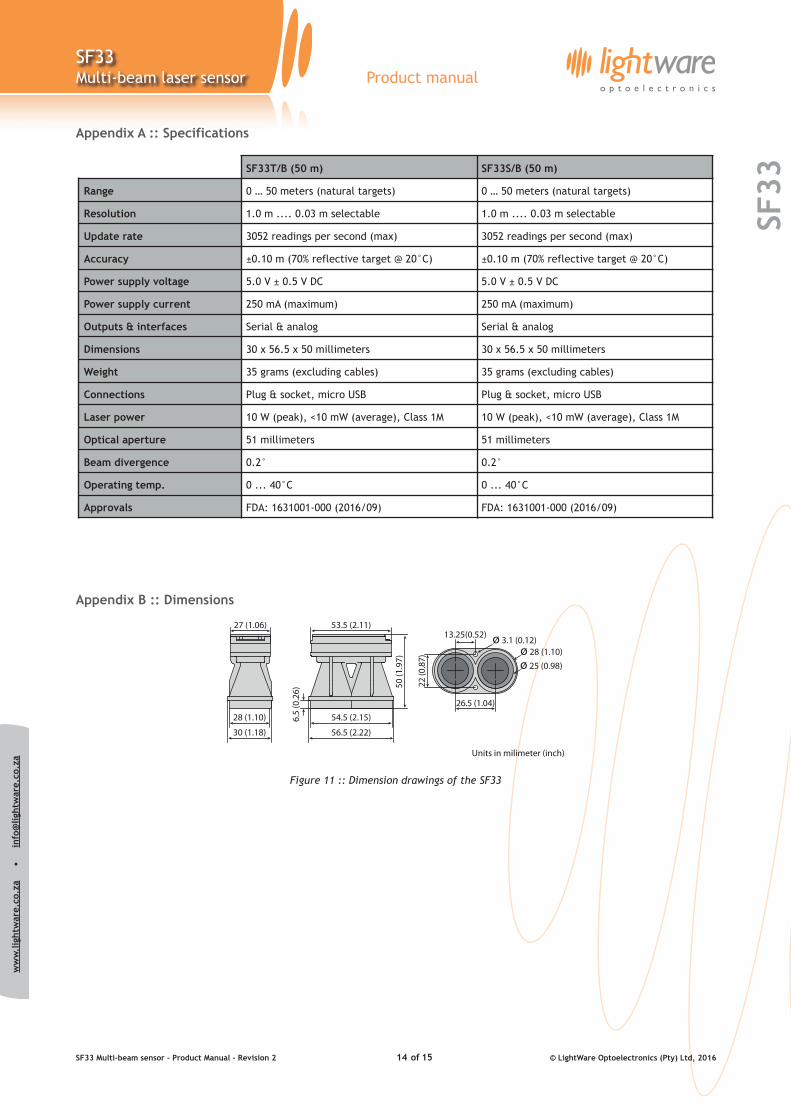
Appendix A :: Specifications
Appendix B :: Dimensions
Figure 11 :: Dimension drawings of the SF33
SF33T/B (50 m) SF33S/B (50 m)
Range 0 … 50 meters (natural targets) 0 … 50 meters (natural targets)
Resolution 1.0 m .... 0.03 m selectable 1.0 m .... 0.03 m selectable
Update rate 3052 readings per second (max) 3052 readings per second (max)
Accuracy ±0.10 m (70% reflective target @ 20°C) ±0.10 m (70% reflective target @ 20°C)
Power supply voltage 5.0 V ± 0.5 V DC 5.0 V ± 0.5 V DC
Power supply current 250 mA (maximum) 250 mA (maximum)
Outputs & interfaces Serial & analog Serial & analog
Dimensions 30 x 56.5 x 50 millimeters 30 x 56.5 x 50 millimeters
Weight 35 grams (excluding cables) 35 grams (excluding cables)
Connections Plug & socket, micro USB Plug & socket, micro USB
Laser power 10 W (peak), <10 mW (average), Class 1M 10 W (peak), <10 mW (average), Class 1M
Optical aperture 51 millimeters 51 millimeters
Beam divergence 0.2° 0.2°
Operating temp. 0 ... 40°C 0 ... 40°C
Approvals FDA: 1631001-000 (2016/09) FDA: 1631001-000 (2016/09)
SF33 Multi-beam sensor - Product Manual - Revision 2 of © LightWare Optoelectronics (Pty) Ltd, 201614 15
ww
w.l
ight
war
e.co
.za
•
i
nfo@
light
war
e.co
.za
SF33
SF33Multi-beam laser sensor Product manual
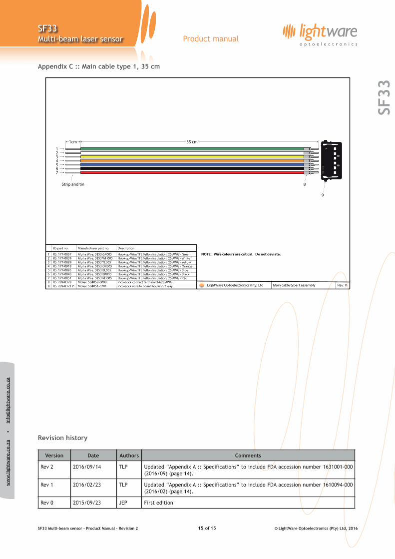
Appendix C :: Main cable type 1, 35 cm
Revision history
Version Date Authors Comments
Rev 2 2016/09/14 TLP Updated “Appendix A :: Specifications” to include FDA accession number 1631001-000 (2016/09) (page 14).
Rev 1 2016/02/23 TLP Updated “Appendix A :: Specifications” to include FDA accession number 1610094-000 (2016/02) (page 14).
Rev 0 2015/09/23 JEP First edition
SF33 Multi-beam sensor - Product Manual - Revision 2 of © LightWare Optoelectronics (Pty) Ltd, 201615 15