Embed Size (px)
Citation preview
SafeLink SF6 Insulated Ring Main Unit Installation and Operating Instructions
ABB Power Technology Products Division abb NZABBSL 3001
SafeLink SF6 Insulated Ring Main Unit Installation and Operating Instructions
ABB Limited i
abb
Product Overview ABB's type-tested SafeLink ring main unit (RMU) is an SF6 insulated RMU utilising the latest developments in switchgear technology to provide a very compact switchgear solution. SafeLink is a completely sealed system with a stainless steel tank containing all live parts and switching functions. A hermetically sealed tank separated from the outside environment ensures a high level of reliability as well as personal safety and a virtually maintenance free system. SafeLink is manufactured according to the latest environmental and quality standards. The ABB assembly plant is certified according to ISO9001 (Quality) and ISO14001 (Environmental). SafeLink equipment conforms to all applicable IEC standards. This manual provides detailed information on the handling, installation, commissioning and operation of SafeLink. The range of SafeLink products and the specifications of the equipment are subject to change without notice as product features and benefits are added. For more information, or to discuss SafeLink operation, please contact your local ABB office or the ABB factory in New Zealand:
ABB Ltd Ph: +64 9 837 1234 Power Technology Products Division Fax: +64 9 837 2950 133 Central Park Drive PO Box 83-203 Auckland 8 New Zealand
SafeLink SF6 Insulated Ring Main Unit Installation and Operating Instructions
ABB Limited ii NZABBSL 3001
abb
Contents 1 GENERAL DESCRIPTION ........................................................................................................................... 1
1.1 SAFELINK FEATURES ................................................................................................................................... 2 1.1.1 CFC, CCC,CF, DF, DC.................................................................................................................................. 3 1.1.2 CFCC, CCCC, CFCD..................................................................................................................................... 4 1.1.3 CFCF ............................................................................................................................................................. 5 1.1.4 Outdoor Enclosure......................................................................................................................................... 6
2 TECHNICAL DATA....................................................................................................................................... 7 2.1 OPERATING CONDITIONS ............................................................................................................................. 7 2.2 ELECTRICAL DATA ....................................................................................................................................... 7 2.3 RATING LABEL............................................................................................................................................. 8 2.4 STANDARD COMPLIANCE.............................................................................................................................. 8
3 TRANSPORT & HANDLING......................................................................................................................... 9 3.1 STORAGE.................................................................................................................................................... 9 3.2 TRANSPORTING ........................................................................................................................................... 9 3.3 INSPECTION OF UNIT.................................................................................................................................... 9 3.4 DIMENSIONS & WEIGHTS ............................................................................................................................. 9
4 INSTALLATION .......................................................................................................................................... 10 4.1 FOUNDATIONS ........................................................................................................................................... 10 4.2 MAIN CABLE BOXES................................................................................................................................... 11 4.3 CABLE CONNECTION.................................................................................................................................. 11
4.3.1 Steps for Cable Connection ......................................................................................................................... 11 4.3.2 Cable termination boots ............................................................................................................................... 11
4.4 OUTDOOR ENCLOSURE.............................................................................................................................. 12 5 OPERATION ............................................................................................................................................... 13
5.1 GAS DENSITY GAUGE ................................................................................................................................ 13 5.2 GENERAL SWITCH OPERATION ................................................................................................................... 14 5.3 SWITCH-FUSE RESET ................................................................................................................................ 15 5.4 FUSE REPLACEMENT ................................................................................................................................. 15 5.5 FUSE TYPES AND REPLACEMENT................................................................................................................ 17
5.5.1 Fuse Tables ................................................................................................................................................. 17 5.6 CABLE BOX ............................................................................................................................................... 18 5.7 CABLE TESTING......................................................................................................................................... 18
6 MAINTENANCE .......................................................................................................................................... 19 6.1 ENVIRONMENTAL ....................................................................................................................................... 19 6.2 MAINTENANCE........................................................................................................................................... 19 6.3 GAS SAMPLING AND FILLING....................................................................................................................... 19 6.4 ENVIRONMENTAL CERTIFICATION................................................................................................................ 20
6.4.1 Life Expectancy Of Product ......................................................................................................................... 20 6.4.2 Recycling Capability..................................................................................................................................... 20 6.4.3 End-Of-Life .................................................................................................................................................. 20
7 ACCESSORIES .......................................................................................................................................... 21 7.1 HORSTMANN EKA-3 .................................................................................................................................. 21 7.2 HORSTMANN ALPHA/E AND ALPHA/M ......................................................................................................... 21 7.3 VOLTAGE INDICATOR.................................................................................................................................. 21 7.4 PHASE BALANCE TESTER........................................................................................................................... 21 7.5 AUXILIARY SWITCH .................................................................................................................................... 22 7.6 MOTOR OPERATOR.................................................................................................................................... 22 7.7 GAS DENSITY MONITOR............................................................................................................................. 22 7.8 SHUNT TRIP .............................................................................................................................................. 23 7.9 CABLE CLAMP RAIL.................................................................................................................................... 23 7.10 BOTTOM COVER/GLAND PLATES............................................................................................................. 23 7.11 EMERGENCY TRIP .................................................................................................................................. 23 7.12 GAS FILLING/SAMPLING ADAPTOR KIT..................................................................................................... 24 7.13 EXTENDED HEIGHT PLINTH..................................................................................................................... 24 7.14 LIFTING FRAME ...................................................................................................................................... 24
SafeLink SF6 Insulated Ring Main Unit Installation and Operating Instructions
ABB Limited 1 NZABBSL 3001
abb
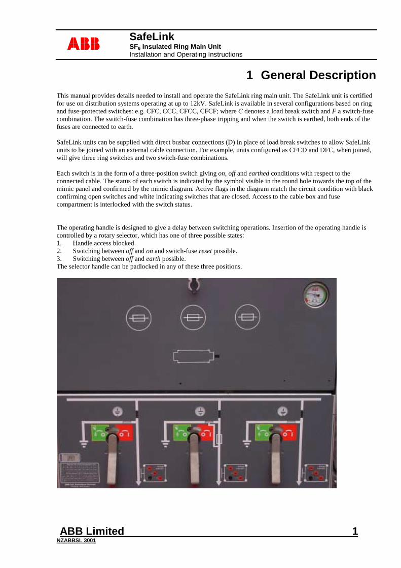
1 General Description This manual provides details needed to install and operate the SafeLink ring main unit. The SafeLink unit is certified for use on distribution systems operating at up to 12kV. SafeLink is available in several configurations based on ring and fuse-protected switches: e.g. CFC, CCC, CFCC, CFCF; where C denotes a load break switch and F a switch-fuse combination. The switch-fuse combination has three-phase tripping and when the switch is earthed, both ends of the fuses are connected to earth. SafeLink units can be supplied with direct busbar connections (D) in place of load break switches to allow SafeLink units to be joined with an external cable connection. For example, units configured as CFCD and DFC, when joined, will give three ring switches and two switch-fuse combinations. Each switch is in the form of a three-position switch giving on, off and earthed conditions with respect to the connected cable. The status of each switch is indicated by the symbol visible in the round hole towards the top of the mimic panel and confirmed by the mimic diagram. Active flags in the diagram match the circuit condition with black confirming open switches and white indicating switches that are closed. Access to the cable box and fuse compartment is interlocked with the switch status. The operating handle is designed to give a delay between switching operations. Insertion of the operating handle is controlled by a rotary selector, which has one of three possible states: 1. Handle access blocked. 2. Switching between off and on and switch-fuse reset possible. 3. Switching between off and earth possible. The selector handle can be padlocked in any of these three positions.
SafeLink SF6 Insulated Ring Main Unit Installation and Operating Instructions
ABB Limited 2 NZABBSL 3001
abb
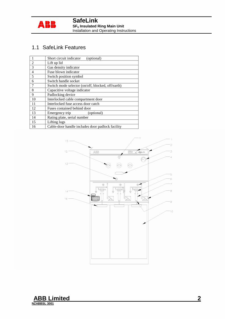
1.1 SafeLink Features 1 Short circuit indicator (optional) 2 Lift up lid 3 Gas density indicator 4 Fuse blown indicator 5 Switch position symbol 6 Switch handle socket 7 Switch mode selector (on/off, blocked, off/earth) 8 Capacitive voltage indicator 9 Padlocking device 10 Interlocked cable compartment door 11 Interlocked fuse access door catch 12 Fuses contained behind door 13 Emergency trip (optional) 14 Rating plate, serial number 15 Lifting lugs 16 Cable-door handle includes door padlock facility
SF6 min. pressure @ 20°C: 1.1bar abs. Mass: 250kg.
Im a
50kA
Str iker
Med.
IEC
420
, IEC
129
ABB Ltd, Switchgear DivisionAuckland New Zealand
RMU IEC 298. Switch Configuration:CFC
Uw
95kV
Uw
95kV
Seria
l No.
IEC
265
, IEC
129
Ur
12kV
Ur
12kV
n
100
n
100
I r
630A
fr
50Hz
I r
200A
fr
50Hz
tk
3sec .
Ik
20kA
Fu selink
Max 100A
In. max
70A
SafeLink SF6 Insulated Ring Main Unit Installation and Operating Instructions
ABB Limited 3 NZABBSL 3001
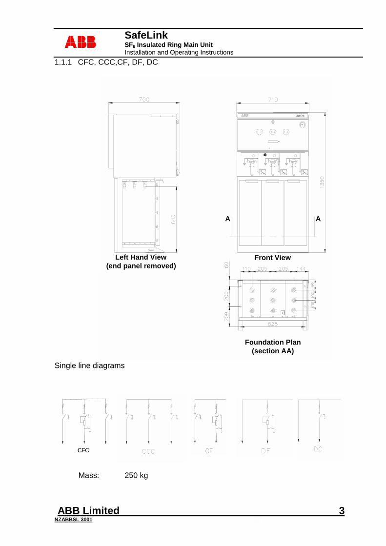
abb1.1.1 CFC, CCC,CF, DF, DC
Single line diagrams
Mass: 250 kg
A A
Front ViewLeft Hand View(end panel removed)
Foundation Plan(section AA)
Single Line Diagram CFC
CFC
SafeLink SF6 Insulated Ring Main Unit Installation and Operating Instructions
ABB Limited 4 NZABBSL 3001
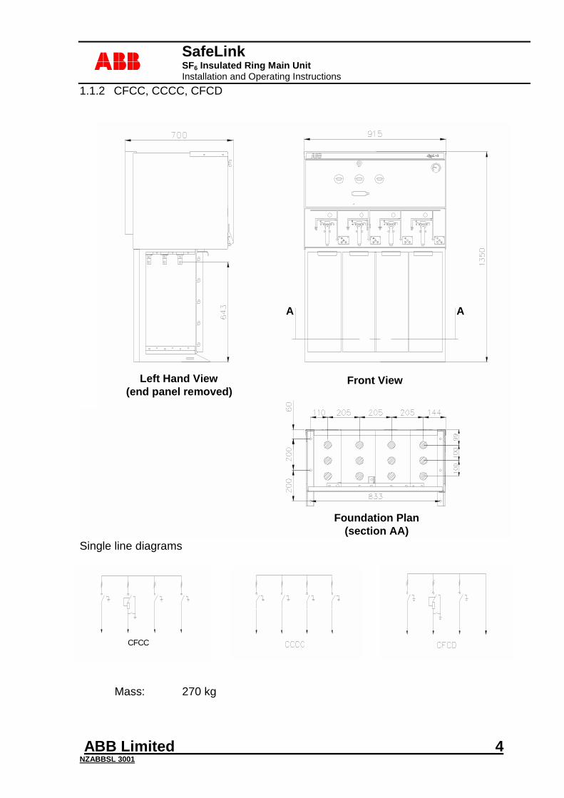
abb1.1.2 CFCC, CCCC, CFCD
AA
Front ViewLeft Hand View(end panel removed)
Foundation Plan(section AA)
Single Line Diagram
Single line diagrams
Mass: 270 kg
CFCC
CFCC
SafeLink SF6 Insulated Ring Main Unit Installation and Operating Instructions
ABB Limited 5 NZABBSL 3001
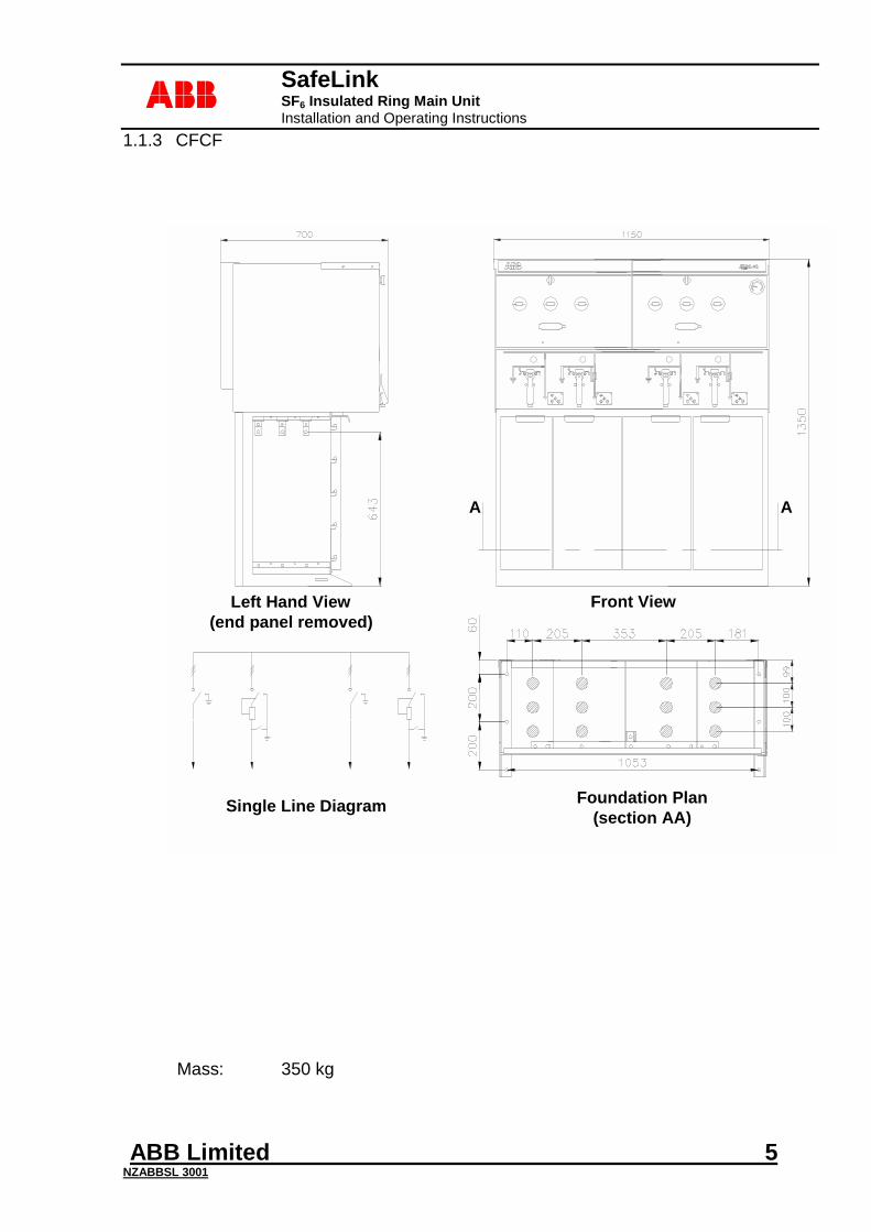
abb1.1.3 CFCF
Mass: 350 kg
Left Hand View(end panel removed)
Front View
A A
Foundation Plan(section AA)Single Line Diagram
CFCF
SafeLink SF6 Insulated Ring Main Unit Installation and Operating Instructions
ABB Limited 6 NZABBSL 3001
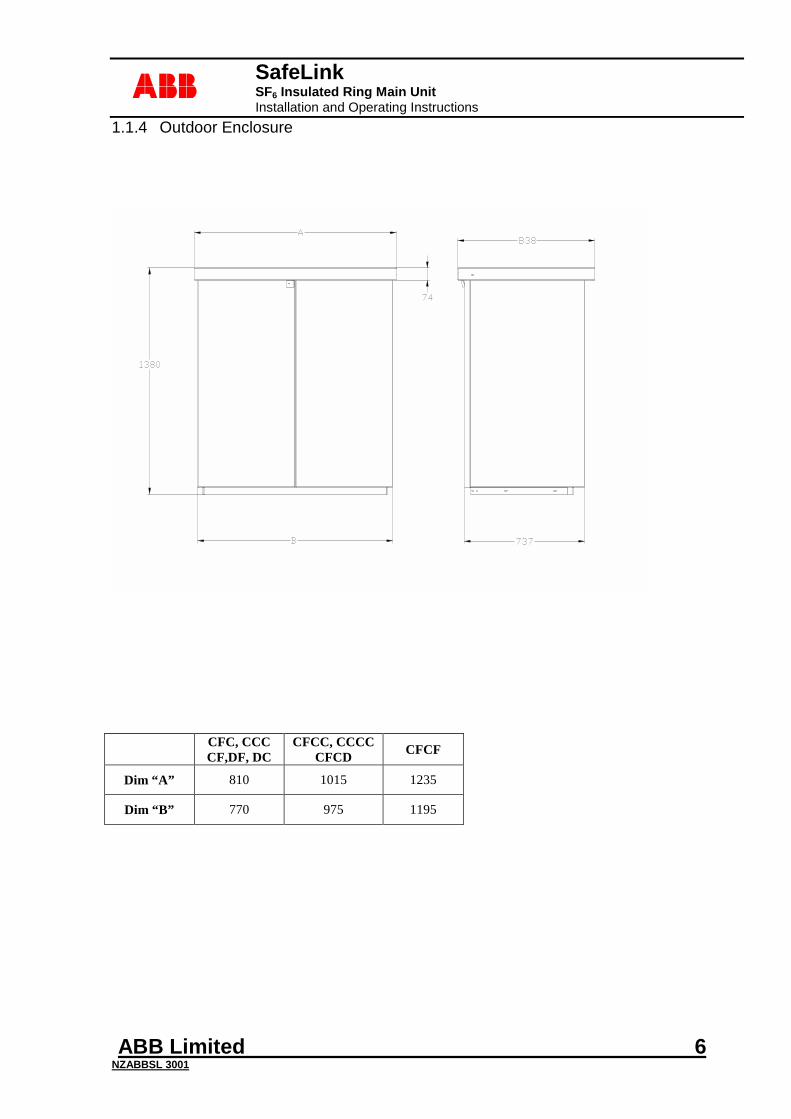
abb1.1.4 Outdoor Enclosure
CFC, CCC
CF,DF, DC CFCC, CCCC
CFCD CFCF
Dim “A” 810 1015 1235
Dim “B” 770 975 1195
SafeLink SF6 Insulated Ring Main Unit Installation and Operating Instructions
ABB Limited 7 NZABBSL 3001
abb
2 Technical Data
2.1 Operating Conditions
Normal Ambient Temperature: -25°C to +40°C Altitude: Up to 1000m above sea level Installation: Indoor or outdoor with an enclosure Standard indoor RMU IP43 Mounted in Outdoor Enclosure
IP55W
Insulating Gas Type: SF6 (IEC 60376) Filling Pressure @ 20°C: 1.2bar abs Quantity: 1kg approximately (CFC) Minimum Operating Pressure: 1.1bar abs
2.2 Electrical Data General Ratings @ 1.1bar abs SF6 Pressure
Rated Voltage: 12kV Lightning impulse Voltage: 95/110kV BIL (optional 75/85kV BIL) Withstand Voltage: 28/32kV for 1 minute (42kV on request) Frequency: 50Hz Rated Current: 630A Withstand Current: 20kA rms Withstand Current Duration: 3sec Internal Arc fault withstand: 20kA Recommended Maximum Cable Size: 300mm² 3-core cable
500mm² single-core cable
Load Break Switch (E3, M2 rating to IEC 60265-1:1998)
Rated Current: 630A Short Circuit Making Current: 50kA peak
Switch-Fuse
Rated Current: 200A Prospective Fault Withstand: 20kA rms
Bushings
Series 400 (DIN 47632) with adapted in-line bolted connection Rated Current: 630A
Fuses
DIN 43625 Maximum. Barrel Length: 292mm Maximum. Diameter: 87mm Maximum. Fuse current rating 160A
Refer to Section 5.5.1 on page 17 for the fuse selection chart.
SafeLink SF6 Insulated Ring Main Unit Installation and Operating Instructions
ABB Limited 8 NZABBSL 3001
abb
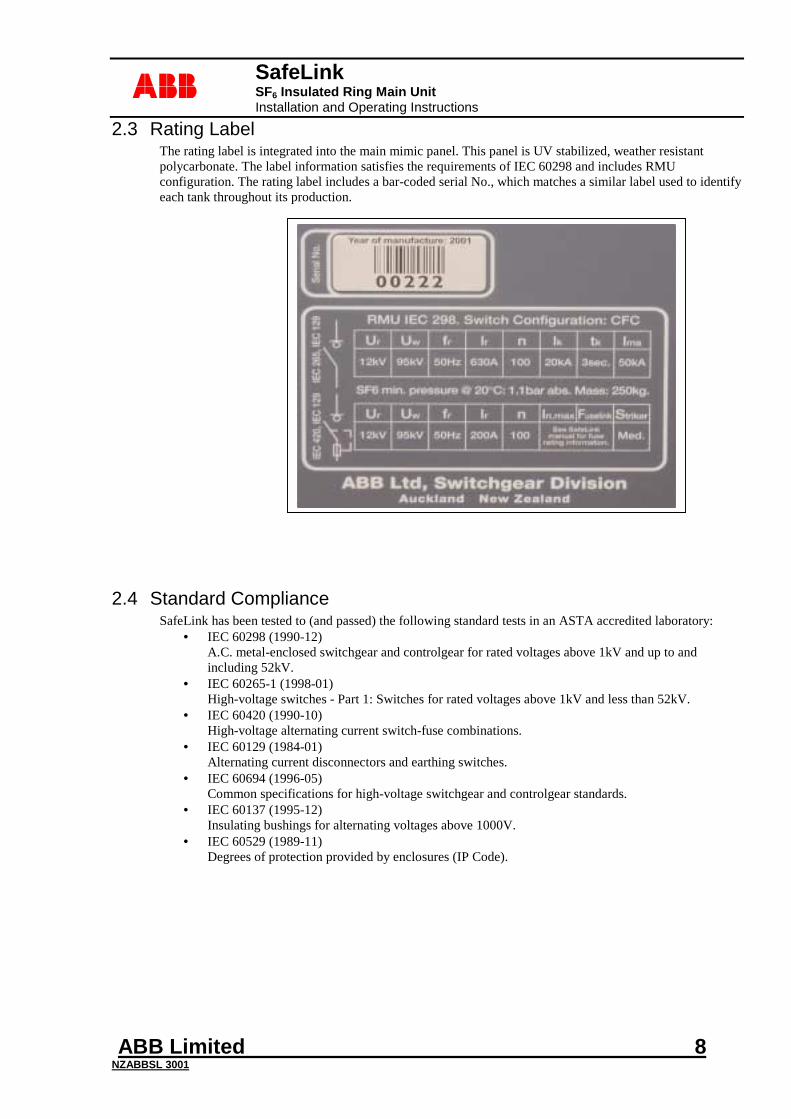
2.3 Rating Label The rating label is integrated into the main mimic panel. This panel is UV stabilized, weather resistant polycarbonate. The label information satisfies the requirements of IEC 60298 and includes RMU configuration. The rating label includes a bar-coded serial No., which matches a similar label used to identify each tank throughout its production.
2.4 Standard Compliance SafeLink has been tested to (and passed) the following standard tests in an ASTA accredited laboratory:
• IEC 60298 (1990-12) A.C. metal-enclosed switchgear and controlgear for rated voltages above 1kV and up to and including 52kV.
• IEC 60265-1 (1998-01) High-voltage switches - Part 1: Switches for rated voltages above 1kV and less than 52kV.
• IEC 60420 (1990-10) High-voltage alternating current switch-fuse combinations.
• IEC 60129 (1984-01) Alternating current disconnectors and earthing switches.
• IEC 60694 (1996-05) Common specifications for high-voltage switchgear and controlgear standards.
• IEC 60137 (1995-12) Insulating bushings for alternating voltages above 1000V.
• IEC 60529 (1989-11) Degrees of protection provided by enclosures (IP Code).
SafeLink SF6 Insulated Ring Main Unit Installation and Operating Instructions
ABB Limited 9 NZABBSL 3001
abb
3 Transport & Handling
3.1 Storage SafeLink units must be stored under cover in a dry and well-ventilated area.
3.2 Transporting SafeLink units are shipped from the factory filled with SF6 gas and ready for installation. All units have passed routine tests before leaving the factory. The switchgear is filled with SF6 gas to a pressure of 0.2 bar above atmosphere at 20°C. Bolts, nuts, connections etc associated with sealing must not be adjusted. The units are supplied packed on a wooden pallet or concrete pad to allow fork hoist movement. Lifting eyes are also provided for lifting the RMU only. (They are not to be used for lifting units pre-fitted with concrete pads) . Where the unit is to be fitted with an outdoor enclosure, the enclosure can be supplied as a flat-pack and fitted to the SafeLink following installation. (see section 4.4) Lifting frames are available where SafeLink RMU’s are transported to site pre-fitted to concrete plinth and/or with outdoor enclosure. This allows direct positioning of the unit by crane or hiab truck.
3.3 Inspection of Unit On receipt of the unit, it should be checked for any visible signs of damage. Damage to paintwork, etc should be made good as soon as possible. Check that the gas density gauge is in the green area. If there are any problems with your SafeLink unit please contact your ABB agent.
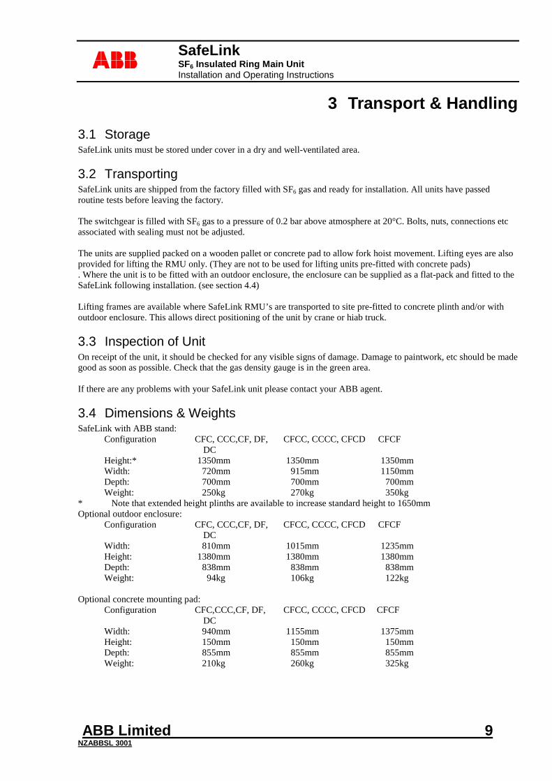
3.4 Dimensions & Weights SafeLink with ABB stand:
Configuration CFC, CCC,CF, DF, DC
CFCC, CCCC, CFCD CFCF
Height:* 1350mm 1350mm 1350mm Width: 720mm 915mm 1150mm Depth: 700mm 700mm 700mm Weight: 250kg 270kg 350kg
* Note that extended height plinths are available to increase standard height to 1650mm Optional outdoor enclosure:
Configuration CFC, CCC,CF, DF, DC
CFCC, CCCC, CFCD CFCF
Width: 810mm 1015mm 1235mm Height: 1380mm 1380mm 1380mm Depth: 838mm 838mm 838mm Weight: 94kg 106kg 122kg
Optional concrete mounting pad:
Configuration CFC,CCC,CF, DF, DC
CFCC, CCCC, CFCD CFCF
Width: 940mm 1155mm 1375mm Height: 150mm 150mm 150mm Depth: 855mm 855mm 855mm Weight: 210kg 260kg 325kg
SafeLink SF6 Insulated Ring Main Unit Installation and Operating Instructions
ABB Limited 10 NZABBSL 3001
abb
4 Installation
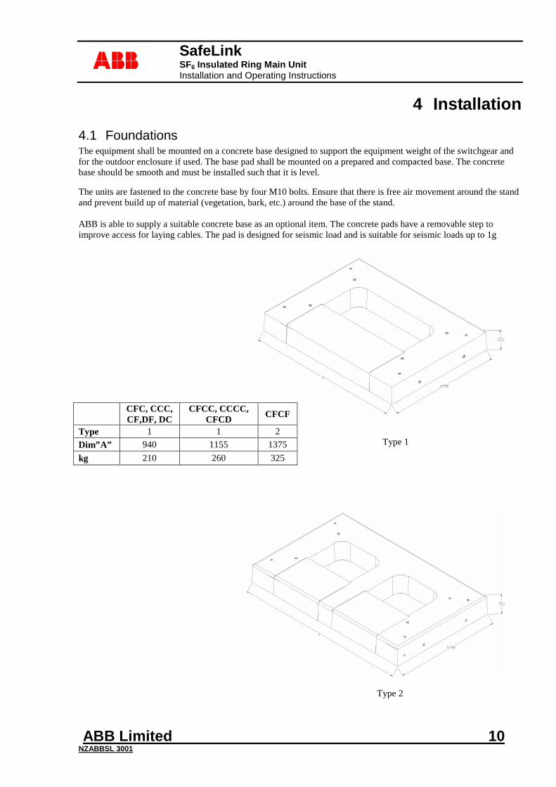
4.1 Foundations The equipment shall be mounted on a concrete base designed to support the equipment weight of the switchgear and for the outdoor enclosure if used. The base pad shall be mounted on a prepared and compacted base. The concrete base should be smooth and must be installed such that it is level.
The units are fastened to the concrete base by four M10 bolts. Ensure that there is free air movement around the stand and prevent build up of material (vegetation, bark, etc.) around the base of the stand.
ABB is able to supply a suitable concrete base as an optional item. The concrete pads have a removable step to improve access for laying cables. The pad is designed for seismic load and is suitable for seismic loads up to 1g
CFC, CCC, CF,DF, DC
CFCC, CCCC, CFCD CFCF
Type 1 1 2 Dim”A” 940 1155 1375 kg 210 260 325
Type 2
Type 1
SafeLink SF6 Insulated Ring Main Unit Installation and Operating Instructions
ABB Limited 11 NZABBSL 3001
abb
4.2 Main Cable Boxes The cable box compartment covers can be removed individually, while the side plates can also be removed for installation and commissioning. This allows all of the bushings to be exposed to give maximum cable termination room. Options available include gland plates, cable support clamps, and their associated brackets.
4.3 Cable Connection The maximum cable recommended is 300mm² 3-core or 500mm² for single-core cables. The bushings for each switch are arranged front to rear. The cable should be prepared for jointing with L1 to the rear. The cable-bushing stem has a 25mm wide pad and lugs should be fitted using high tensile M12 bolts tightened to a maximum of 72Nm.(max bolt length recommended M12 x 35mm) Unused switches should be appropriately terminated with a blank termination.
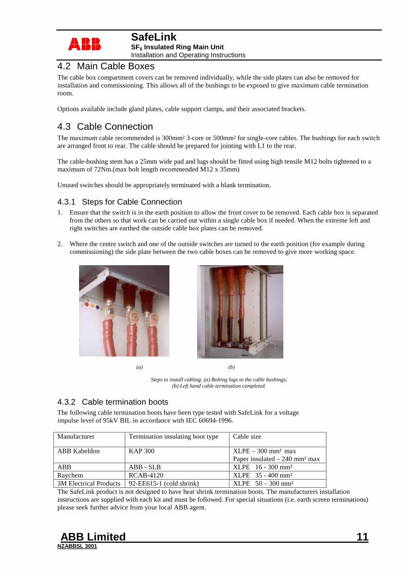
4.3.1 Steps for Cable Connection 1. Ensure that the switch is in the earth position to allow the front cover to be removed. Each cable box is separated
from the others so that work can be carried out within a single cable box if needed. When the extreme left and right switches are earthed the outside cable box plates can be removed.
2. Where the centre switch and one of the outside switches are turned to the earth position (for example during
commissioning) the side plate between the two cable boxes can be removed to give more working space.
(a) (b)
Steps to install cabling. (a) Bolting lugs to the cable bushings;
(b) Left hand cable termination completed.
4.3.2 Cable termination boots The following cable termination boots have been type tested with SafeLink for a voltage impulse level of 95kV BIL in accordance with IEC 60694-1996. Manufacturer Termination insulating boot type Cable size
ABB Kabeldon KAP 300 XLPE – 300 mm² max Paper insulated – 240 mm² max
ABB ABB - SLB XLPE 16 - 300 mm²
Raychem RCAB-4120 XLPE 35 - 400 mm²
3M Electrical Products 92-EE615-1 (cold shrink) XLPE 50 – 300 mm²
The SafeLink product is not designed to have heat shrink termination boots. The manufacturers installation instructions are supplied with each kit and must be followed. For special situations (i.e. earth screen terminations) please seek further advice from your local ABB agent.
SafeLink SF6 Insulated Ring Main Unit Installation and Operating Instructions
ABB Limited 12 NZABBSL 3001
abb
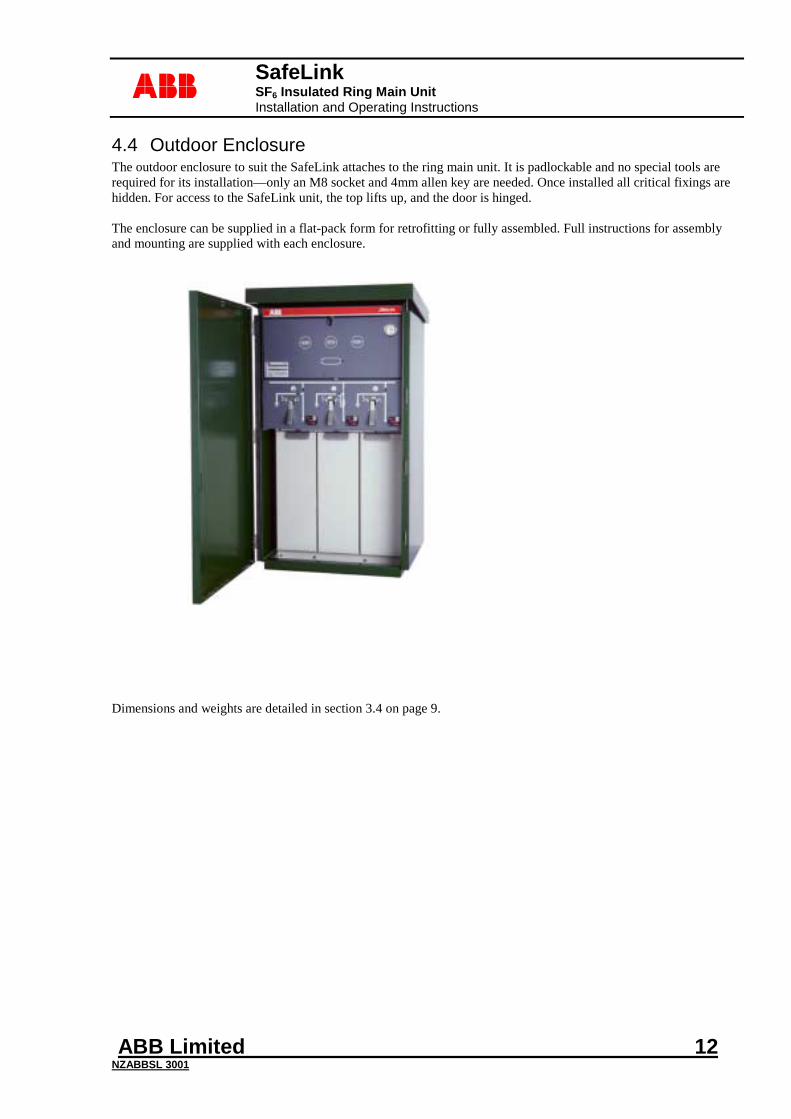
4.4 Outdoor Enclosure The outdoor enclosure to suit the SafeLink attaches to the ring main unit. It is padlockable and no special tools are required for its installation—only an M8 socket and 4mm allen key are needed. Once installed all critical fixings are hidden. For access to the SafeLink unit, the top lifts up, and the door is hinged. The enclosure can be supplied in a flat-pack form for retrofitting or fully assembled. Full instructions for assembly and mounting are supplied with each enclosure.
Dimensions and weights are detailed in section 3.4 on page 9.
SafeLink SF6 Insulated Ring Main Unit Installation and Operating Instructions
ABB Limited 13 NZABBSL 3001
abb
5 Operation The following sections describe the operating procedure for SafeLink. There are no parts within the SafeLink unit that require user attention other than the fuses and the gas density gauge.
Equipment suffering faults or damage must be returned to your supplier for servicing.
Ensure the gauge reads in the green area before switching.
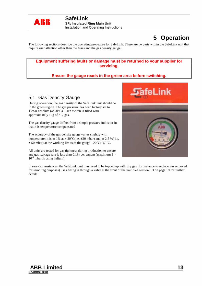
5.1 Gas Density Gauge During operation, the gas density of the SafeLink unit should be in the green region. The gas pressure has been factory set to 1.2bar absolute (at 20°C). Each switch is filled with approximately 1kg of SF6 gas. The gas density gauge differs from a simple pressure indicator in that it is temperature compensated The accuracy of the gas density gauge varies slightly with temperature; it is ± 1% at + 20°C(i.e. ±20 mbar) and ± 2.5 %( i.e. ± 50 mbar) at the working limits of the gauge - 20°C/+60°C. All units are tested for gas tightness during production to ensure any gas leakage rate is less than 0.1% per annum (maximum 3 × 10⁻⁶ mbarl/s using helium). In rare circumstances, the SafeLink unit may need to be topped up with SF6 gas (for instance to replace gas removed for sampling purposes). Gas filling is through a valve at the front of the unit. See section 6.3 on page 19 for further details.
SafeLink SF6 Insulated Ring Main Unit Installation and Operating Instructions
ABB Limited 14 NZABBSL 3001
abb
5.2 General Switch Operation All switches (ring and fuse) have the same basic operating procedure. Select the operation desired with the rotary selector. The spring-loaded selector must engage with the location hole in the panel. Symbols to the right (Red) and left (Green) of the handle hole indicate the operations possible in the respective positions. Access for the operating handle is controlled by a rotary selector that has one of three possible states:
1. Handle access blocked; no switching possible. 2. Switch able to operate from off to on (and vice versa) Red zone 3. Switch able to operate from earth to off (and vice versa). Green zone
The selector can be padlocked in any of these three positions. From off status, selection of either earth or main switch operation is possible. From on status, earth switch operation is not possible (the switch must first be returned to off). Likewise, from earthed status the main switch operation is not possible. After selecting the desired operation insert the handle and rotate in the direction indicated by the symbols. For instance, to switch from off to on the handle is rotated clockwise. About 60° rotation is required for switch operation; internal stops provide limits to the movement. The operating handle has been designed to give a delay between operations either clockwise or anti-clockwise.
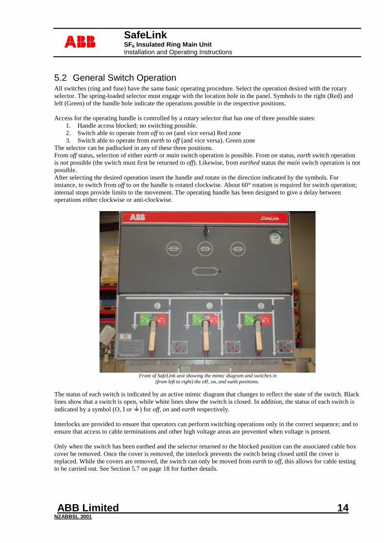
Front of SafeLink unit showing the mimic diagram and switches in
(from left to right) the off, on, and earth positions.
The status of each switch is indicated by an active mimic diagram that changes to reflect the state of the switch. Black lines show that a switch is open, while white lines show the switch is closed. In addition, the status of each switch is indicated by a symbol (O, I or ) for off, on and earth respectively. Interlocks are provided to ensure that operators can perform switching operations only in the correct sequence; and to ensure that access to cable terminations and other high voltage areas are prevented when voltage is present. Only when the switch has been earthed and the selector returned to the blocked position can the associated cable box cover be removed. Once the cover is removed, the interlock prevents the switch being closed until the cover is replaced. While the covers are removed, the switch can only be moved from earth to off, this allows for cable testing to be carried out. See Section 5.7 on page 18 for further details.
SafeLink SF6 Insulated Ring Main Unit Installation and Operating Instructions
ABB Limited 15 NZABBSL 3001
abb
5.3 Switch-Fuse Reset The operation of the switch-fuse is identical to the ring switch except when a fuse has blown. In which case, the striker initiates the automatic opening of the switch. This is indicated by the symbol "O" appearing on the mimic and the word "RESET" being shown above the handle hole. In addition to this, the fuse blown indication on the front of the SafeLink will show. The arrow on the handle socket will indicate that the handle must be rotated anti-clockwise to reset the mechanism (the only possible action). It is important to rotate the handle fully until the stop is felt, to reset the switch correctly.
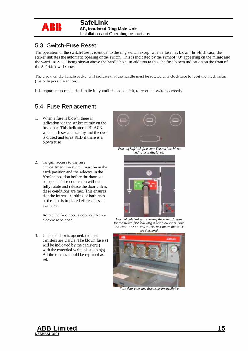
5.4 Fuse Replacement 1. When a fuse is blown, there is
indication via the striker mimic on the fuse door. This indicator is BLACK when all fuses are healthy and the door is closed and turns RED if there is a blown fuse
Front of SafeLink fuse door The red fuse blown
indicator is displayed. 2. To gain access to the fuse
compartment the switch must be in the earth position and the selector in the blocked position before the door can be opened. The door catch will not fully rotate and release the door unless these conditions are met. This ensures that the internal earthing of both ends of the fuse is in place before access is available. Rotate the fuse access door catch anti-clockwise to open.
Front of SafeLink unit showing the mimic diagram for the switch-fuse following a fuse blow event. Note the word ‘RESET’ and the red fuse blown indicator
are displayed. 3. Once the door is opened, the fuse
canisters are visible. The blown fuse(s) will be indicated by the canister(s) with the extended white plastic pin(s). All three fuses should be replaced as a set.
Fuse door open and fuse canisters available.
SafeLink SF6 Insulated Ring Main Unit Installation and Operating Instructions
ABB Limited 16 NZABBSL 3001
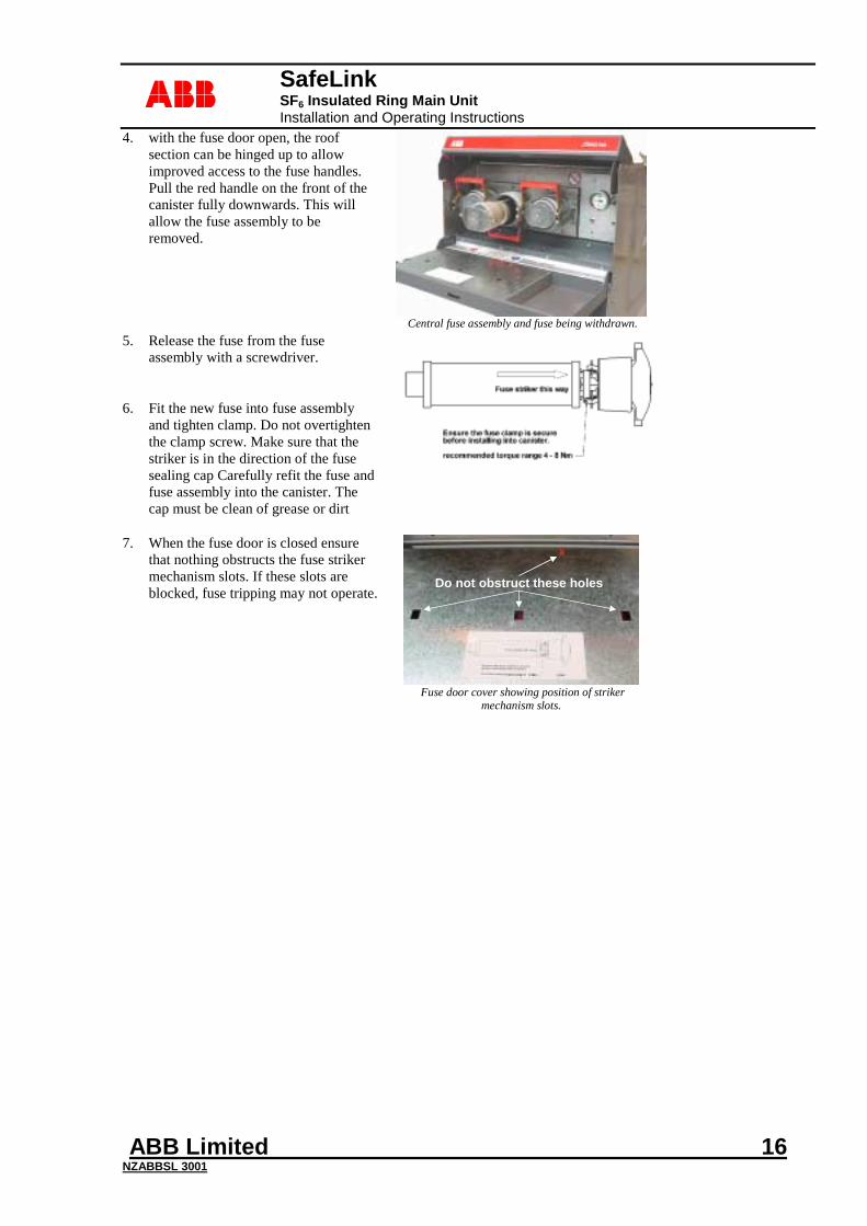
abb4. with the fuse door open, the roof
section can be hinged up to allow improved access to the fuse handles. Pull the red handle on the front of the canister fully downwards. This will allow the fuse assembly to be removed.
Central fuse assembly and fuse being withdrawn.
5. Release the fuse from the fuse assembly with a screwdriver.
6. Fit the new fuse into fuse assembly
and tighten clamp. Do not overtighten the clamp screw. Make sure that the striker is in the direction of the fuse sealing cap Carefully refit the fuse and fuse assembly into the canister. The cap must be clean of grease or dirt
7. When the fuse door is closed ensure that nothing obstructs the fuse striker mechanism slots. If these slots are blocked, fuse tripping may not operate.
Do not obstruct these holesDo not obstruct these holes
Fuse door cover showing position of striker
mechanism slots.
SafeLink SF6 Insulated Ring Main Unit Installation and Operating Instructions
ABB Limited 17 NZABBSL 3001
abb
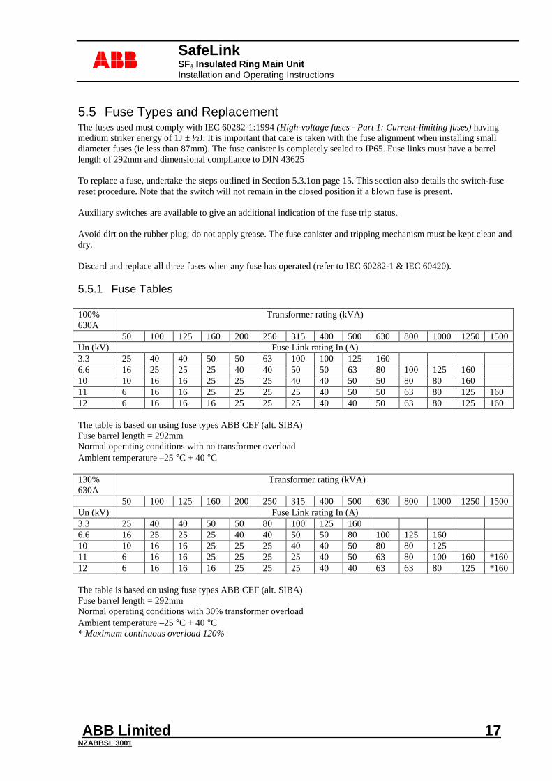
5.5 Fuse Types and Replacement The fuses used must comply with IEC 60282-1:1994 (High-voltage fuses - Part 1: Current-limiting fuses) having medium striker energy of 1J ± ½J. It is important that care is taken with the fuse alignment when installing small diameter fuses (ie less than 87mm). The fuse canister is completely sealed to IP65. Fuse links must have a barrel length of 292mm and dimensional compliance to DIN 43625 To replace a fuse, undertake the steps outlined in Section 5.3.1on page 15. This section also details the switch-fuse reset procedure. Note that the switch will not remain in the closed position if a blown fuse is present. Auxiliary switches are available to give an additional indication of the fuse trip status. Avoid dirt on the rubber plug; do not apply grease. The fuse canister and tripping mechanism must be kept clean and dry. Discard and replace all three fuses when any fuse has operated (refer to IEC 60282-1 & IEC 60420).
5.5.1 Fuse Tables
100% 630A
Transformer rating (kVA)
50 100 125 160 200 250 315 400 500 630 800 1000 1250 1500 Un (kV) Fuse Link rating In (A) 3.3 25 40 40 50 50 63 100 100 125 160 6.6 16 25 25 25 40 40 50 50 63 80 100 125 160 10 10 16 16 25 25 25 40 40 50 50 80 80 160 11 6 16 16 25 25 25 25 40 50 50 63 80 125 160 12 6 16 16 16 25 25 25 40 40 50 63 80 125 160 The table is based on using fuse types ABB CEF (alt. SIBA) Fuse barrel length = 292mm Normal operating conditions with no transformer overload Ambient temperature –25 °C + 40 °C 130% 630A
Transformer rating (kVA)
50 100 125 160 200 250 315 400 500 630 800 1000 1250 1500 Un (kV) Fuse Link rating In (A) 3.3 25 40 40 50 50 80 100 125 160 6.6 16 25 25 25 40 40 50 50 80 100 125 160 10 10 16 16 25 25 25 40 40 50 80 80 125 11 6 16 16 25 25 25 25 40 50 63 80 100 160 *160 12 6 16 16 16 25 25 25 40 40 63 63 80 125 *160 The table is based on using fuse types ABB CEF (alt. SIBA) Fuse barrel length = 292mm Normal operating conditions with 30% transformer overload Ambient temperature –25 °C + 40 °C * Maximum continuous overload 120%
SafeLink SF6 Insulated Ring Main Unit Installation and Operating Instructions
ABB Limited 18 NZABBSL 3001
abb
5.6 Cable Box The cable box has been designed to ensure that arc faults are contained. This is achieved using a double skin design on the side and front panels. To gain access to the cable box the respective switch must first be in the earth position and the selector switch in the blocked position. This allows the cable box cover to be lifted off. This action also engages an interlock to prevent the switch being closed while the cover is removed. When refitting the cable box covers ensure that the cover is pushed fully down onto the locating pins.
5.7 Cable Testing Cable testing first requires that the cable box cover be removed as described above. The switch can be taken out of the earth position to the off position. To allow test connections to be made to the cable, the termination boots must be slid down to reveal the test points on the bushing stems above the terminations. Once the cable box cover is removed, the switch cannot be turned to the on position. The switch must be returned to the earth position before the cover is refitted. The cover catch locks automatically once the switch is taken out of the earth position.
Cable testing should be carried out in accordance with the cable manufacturer’s recommended practice.
It is important that the terminations be done in the manner outlined in section 4.3 on page 11
SafeLink SF6 Insulated Ring Main Unit Installation and Operating Instructions
ABB Limited 19 NZABBSL 3001
abb
6 Maintenance
6.1 Environmental The SafeLink switching enclosure is a gas-tight welded stainless steel compartment able to withstand a harsh environment. However, it is important that the base of the SafeLink installation be kept free of vegetation or other material to prevent corrosion of the stand and/or enclosure.
6.2 Maintenance All components within the SF6 insulated tank are maintenance free for the life expectancy of the unit. The tank is made of stainless steel. Scratches or other damage to panels must be repaired. Mechanical parts located outside the sealed tank are surface treated or made of corrosion resistant materials. Moving parts are lubricated, as necessary during manufacture, for the unit’s life expectancy. Units installed in extreme conditions will require inspection depending on the nature of the environment. Where an outdoor enclosure is used, this should be checked periodically for scratches or corrosion and the base of the stand must be kept clear of vegetation and well ventilated.
6.3 Gas Sampling and Filling The gas density gauge on the front of the SafeLink shows the density of SF6 gas in the unit. All units are tested to ensure that any leakage rate is so low as to give a thirty-year service life. During switching, the arc formed will cause the gas to dissociate. Once the arc is extinguished the SF6 reforms. A molecular sieve is fitted inside the switching enclosure to absorb any remaining decomposition products. When samples are required these are taken through the Dilo fitting of the gas density gauge on the front of the unit in the fuse compartment. Therefore, the fused switch must be switched to the earth position and the selector placed in the blocked position. The sample must be taken with the sampling kit available from ABB. This will ensure that any gas escaping during the sampling process is minimised. Gas is added through the same connection used to take samples. The ABB filling adaptor allows the pressure inside the switch to be monitored during filling. Full details are included with the filling adaptor.
SafeLink SF6 Insulated Ring Main Unit Installation and Operating Instructions
ABB Limited 20 NZABBSL 3001
abb
6.4 Environmental Certification Environmental Declaration For SafeLink Sf6 Insulated Ring Main Unit
6.4.1 Life Expectancy Of Product The product complies with the requirements denoted by IEC 60298. The designed life span under indoor service condition exceeds 30 years (IEC 60298 annex GG). The switchgear is gas-tight with an expected diffusion rate of less then 0.1% per annum. Referring to the reference-pressure of 1.2 bar, the switchgear will maintain gas-tightness and a gas-pressure better than 1.1 bar* throughout its designed life span. (* at 20°C)
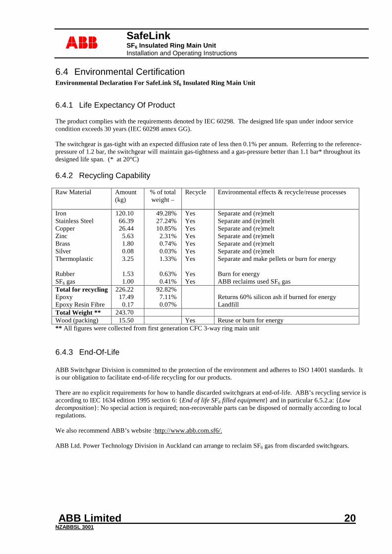
6.4.2 Recycling Capability Raw Material Amount
(kg) % of total weight –
Recycle Environmental effects & recycle/reuse processes
Iron Stainless Steel Copper Zinc Brass Silver Thermoplastic Rubber SF6 gas
120.10 66.39 26.44
5.63 1.80 0.08 3.25
1.53 1.00
49.28% 27.24% 10.85%
2.31% 0.74% 0.03% 1.33%
0.63% 0.41%
Yes Yes Yes Yes Yes Yes Yes Yes Yes
Separate and (re)melt Separate and (re)melt Separate and (re)melt Separate and (re)melt Separate and (re)melt Separate and (re)melt Separate and make pellets or burn for energy Burn for energy ABB reclaims used SF6 gas
Total for recycling Epoxy Epoxy Resin Fibre
226.22 17.49
0.17
92.82% 7.11% 0.07%
Returns 60% silicon ash if burned for energy Landfill
Total Weight ** 243.70 Wood (packing) 15.50 Yes Reuse or burn for energy ** All figures were collected from first generation CFC 3-way ring main unit
6.4.3 End-Of-Life ABB Switchgear Division is committed to the protection of the environment and adheres to ISO 14001 standards. It is our obligation to facilitate end-of-life recycling for our products. There are no explicit requirements for how to handle discarded switchgears at end-of-life. ABB’s recycling service is according to IEC 1634 edition 1995 section 6: {End of life SF6 filled equipment} and in particular 6.5.2.a: {Low decomposition}: No special action is required; non-recoverable parts can be disposed of normally according to local regulations. We also recommend ABB’s website :http://www.abb.com.sf6/. ABB Ltd. Power Technology Division in Auckland can arrange to reclaim SF6 gas from discarded switchgears.
SafeLink SF6 Insulated Ring Main Unit Installation and Operating Instructions
ABB Limited 21 NZABBSL 3001
abb
7 Accessories
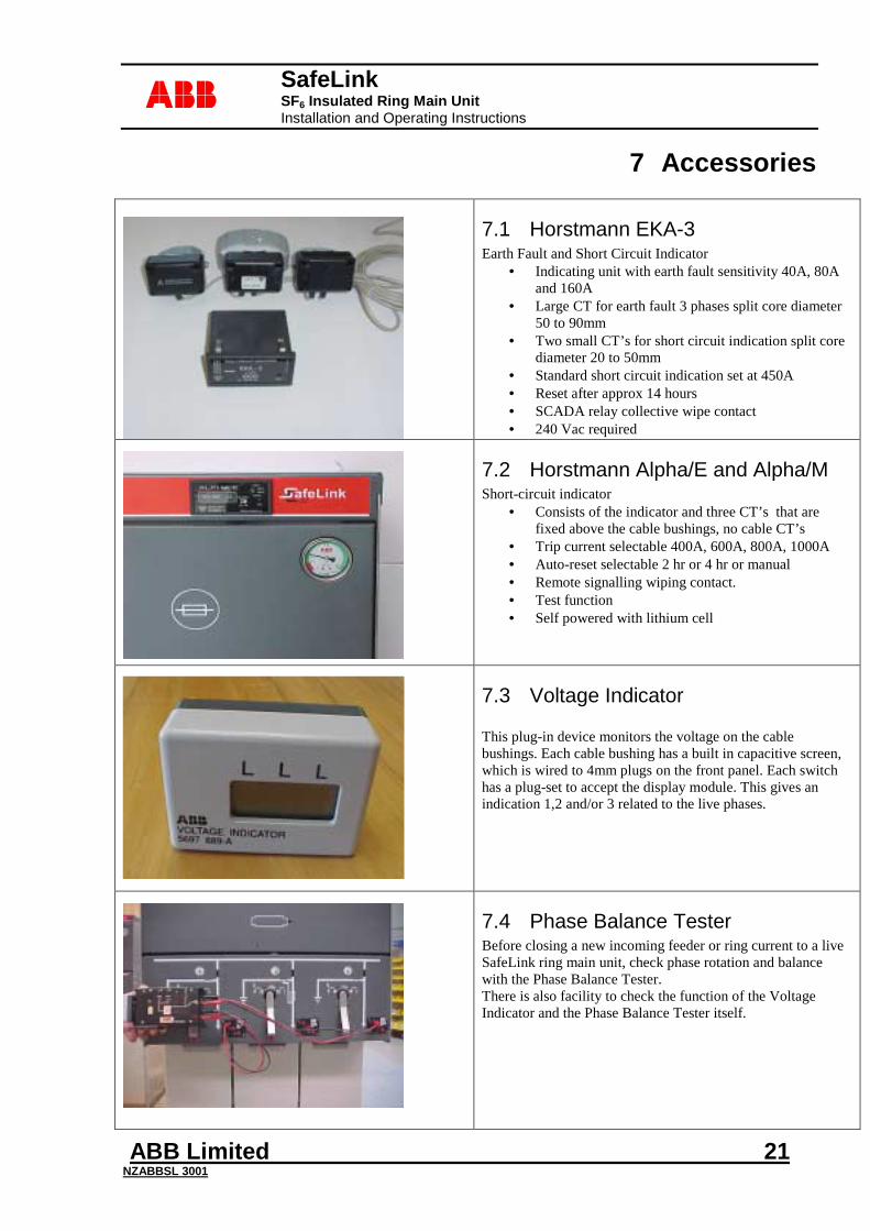
7.1 Horstmann EKA-3 Earth Fault and Short Circuit Indicator
• Indicating unit with earth fault sensitivity 40A, 80A and 160A
• Large CT for earth fault 3 phases split core diameter 50 to 90mm
• Two small CT’s for short circuit indication split core diameter 20 to 50mm
• Standard short circuit indication set at 450A • Reset after approx 14 hours • SCADA relay collective wipe contact • 240 Vac required
7.2 Horstmann Alpha/E and Alpha/M Short-circuit indicator
• Consists of the indicator and three CT’s that are fixed above the cable bushings, no cable CT’s
• Trip current selectable 400A, 600A, 800A, 1000A • Auto-reset selectable 2 hr or 4 hr or manual • Remote signalling wiping contact. • Test function • Self powered with lithium cell
7.3 Voltage Indicator This plug-in device monitors the voltage on the cable bushings. Each cable bushing has a built in capacitive screen, which is wired to 4mm plugs on the front panel. Each switch has a plug-set to accept the display module. This gives an indication 1,2 and/or 3 related to the live phases.
7.4 Phase Balance Tester Before closing a new incoming feeder or ring current to a live SafeLink ring main unit, check phase rotation and balance with the Phase Balance Tester. There is also facility to check the function of the Voltage Indicator and the Phase Balance Tester itself.
SafeLink SF6 Insulated Ring Main Unit Installation and Operating Instructions
ABB Limited 22 NZABBSL 3001
abb
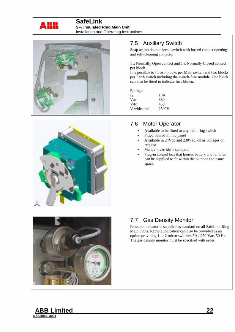
7.5 Auxiliary Switch Snap action double-break switch with forced contact opening and self–cleaning contacts. 1 x Normally Open contact and 1 x Normally Closed contact per block. It is possible to fit two blocks per Main switch and two blocks per Earth switch including the switch-fuse module. One block can also be fitted to indicate fuse blown. Ratings: Ith 10A Vac 380 Vdc 450 V withstand 2500V
7.6 Motor Operator • Available to be fitted to any main ring switch • Fitted behind mimic panel • Available in 24Vdc and 230Vac, other voltages on
request • Manual override is standard • Plug-in control box that houses battery and remotes
can be supplied to fit within the outdoor enclosure space.
7.7 Gas Density Monitor Pressure indicator is supplied as standard on all SafeLink Ring Main Units. Remote indication can also be provided as an option providing 1 or 2 micro switches 5A / 250 Vac, 50 Hz. The gas density monitor must be specified with order.
SafeLink SF6 Insulated Ring Main Unit Installation and Operating Instructions
ABB Limited 23 NZABBSL 3001
abb
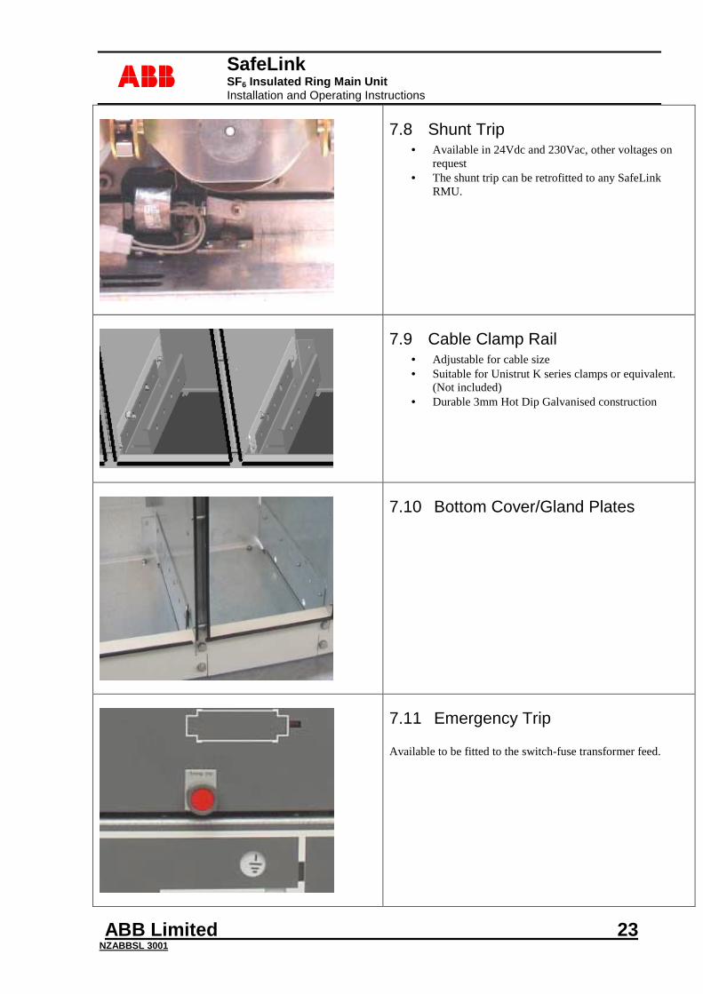
7.8 Shunt Trip • Available in 24Vdc and 230Vac, other voltages on
request • The shunt trip can be retrofitted to any SafeLink
RMU.
7.9 Cable Clamp Rail • Adjustable for cable size • Suitable for Unistrut K series clamps or equivalent.
(Not included) • Durable 3mm Hot Dip Galvanised construction
7.10 Bottom Cover/Gland Plates
7.11 Emergency Trip Available to be fitted to the switch-fuse transformer feed.
SafeLink SF6 Insulated Ring Main Unit Installation and Operating Instructions
ABB Limited 24 NZABBSL 3001
abb
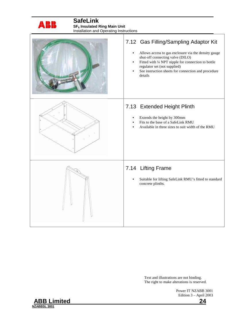
7.12 Gas Filling/Sampling Adaptor Kit
• Allows access to gas enclosure via the density gauge shut-off connecting valve (DILO)
• Fitted with ¼ NPT nipple for connection to bottle regulator set (not supplied)
• See instruction sheets for connection and procedure details
7.13 Extended Height Plinth
• Extends the height by 300mm • Fits to the base of a SafeLink RMU • Available in three sizes to suit width of the RMU
7.14 Lifting Frame
• Suitable for lifting SafeLink RMU’s fitted to standard concrete plinths.
Text and illustrations are not binding. The right to make alterations is reserved.
Power IT NZABB 3001
Edition 3 – April 2003