Embed Size (px)
Citation preview
DEKALB COUNTY DWM CMOM SEWER MAPPING PROGRAM
DECEMBER 2014
I
Sewer Mapping Program
Department of Watershed Management (DWM) Capacity, Management, Operations, and
Maintenance (CMOM) Program
DECEMBER 2014
DEKALB COUNTY DWM CMOM SEWER MAPPING PROGRAM
DECEMBER 2014
II
Contents
Contents......................................................................................................................................... ii Acronyms ..................................................................................................................................... iii 1. Sewer Mapping Program Overview ........................................................................ 1-1
1.1 Introduction ...................................................................................................... 1-1 1.2 Regulatory Drivers .......................................................................................... 1-2 1.3 Purpose and Goals .......................................................................................... 1-2 1.4 Program Resources .......................................................................................... 1-2
1.4.1 Staff ....................................................................................................... 1-2 1.4.2 Equipment ........................................................................................... 1-3
2. Program Implementation ........................................................................................... 2-1 2.1 Program Activities .................................................................................................. 2-1
2.1.1 Asset Inventory and Mapping Summary ....................................... 2-2 2.1.2 System Mapping Survey Process ..................................................... 2-4 2.1.3 Data Updates ....................................................................................... 2-5 2.1.4 Geographic Tracking of System Problems ...................................... 2-6
2.2 Program Schedule and Enhancements ......................................................... 2-7 3. Program Procedures .................................................................................................... 3-1
3.1 Sewer Mapping Survey Process .................................................................... 3-2 3.2 Updating the Sanitary Sewer GIS Inventory ............................................... 3-4 3.3 Using the Sanitary Sewer GIS Inventory ..................................................... 3-9 3.4 Updating the GIS Software .......................................................................... 3-11
Appendices
Appendix A – Scope of Geographical Location and Inventory of the Wastewater Collection System .............................................................................. A-1
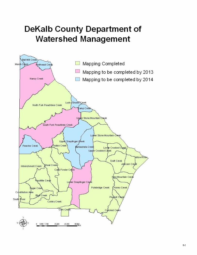
Appendix B – Sewershed Map – Mapping Completed, to be Complete in Year 2013, and in 2014 ................................................................................. B-1
Appendix C – Lift Station Inspection Form-DeKalb County Mapping Project ...C-1

DEKALB COUNTY DWM CMOM SEWER MAPPING PROGRAM
DECEMBER 2014
III
Acronyms
CCTV Closed Circuit Television
CERP Contingency and Emergency Response Plan
C&M Construction and Maintenance
CMMS Computerized Maintenance Management System
CMOM Capacity, Management, Operations, and Maintenance
DWM Department of Watershed Management
ESRI® Environmental Systems Research Institute
EPA U.S. Environmental Protection Agency
EPD Georgia Environmental Protection Division
GAWP Georgia Association of Water Professionals
GIS Geographical Information System
GPS Global Positioning System
GWEF Georgia Water Environment Federation
ID Identification
IMS Information Management System
IS Information Systems
KPI Key Performance Indicator
MACP Manhole Assessment and Certification Program
MNGWPD Metropolitan North Georgia Water Planning District
NASSCO National Association of Sewer Service Companies
RFP Request for Proposal
ROW Rights-of-Way
SOP Standard Operating Procedure
SSO Sanitary Sewer Overflow
DEKALB COUNTY DWM CMOM SEWER MAPPING PROGRAM
DECEMBER 2014
1-1
1. Sewer Mapping Program Overview
1.1 Introduction
DeKalb County (the County) Department of Watershed Management (DWM) CMOM Sewer Mapping Program builds on and significantly expands the County’s pre-existing sewer mapping program. The County currently has the ability to (1) produce certain maps using GIS technology,(2) integrate electronically sewer system locations and attribute data with the County computer-based collection system hydraulic model and the computerized maintenance management systems (CMMS), (3) reproduce maps in a manner that will allow use by all sewer system operation and maintenance crew leaders in the field, and (4) identify and track problems (such as stoppages, service interruptions, infiltration, and SSOs) geographically. However, the County has not been able to perform these various functions on a system-wide basis.
The County has constantly worked to improve its sewer mapping capabilities. Currently, a sewer system mapping and inventory survey project is being completed by County contractors. The project terms include information regarding mapping, inventory, and recording of geographical location of all public and private sanitary sewer manholes (by identifying numbers), public and private sewer mains, force mains and air valves, service line cleanouts, and lift stations in the wastewater collection system. Note, however, that the mapping of private sewers shall not be enforceable under the Consent Decree. Mapping and inventory tasks are conducted by sewer drainage sewershed, with 21 of the 35 sewersheds in the County service area currently completed, the remaining 11 sewersheds are scheduled to be completed by December 2014. (Note: Three sewersheds do not have sewer systems).
The following is an overview of the tasks and capabilities of County’s CMOM Sewer Mapping Program that will be completed or in place at the conclusion of the system-wide mapping and inventory survey project:
The production of more accurate maps with Global Positioning Satellite coordinates of asset attributes as well as other landmarks using GIS technology;
The easier reproduction of maps for use in the field;
The creation of written Standard Operating Procedures (SOP) for managing inventory updates and use and for updating the GIS software;
The improved tracking of problems geographically, such as stoppages, service interruptions, infiltration, and SSOs, and to assist in the planning, scheduling, and prioritization of maintenance; and
Electronic integration of sewer system location and attribute data with the County computer-based collection system hydraulic model and the computerized maintenance management System (CMMS).
DEKALB COUNTY DWM CMOM SEWER MAPPING PROGRAM
DECEMBER 2014
1-2
Current DWM Staffing Resources
Assistant Director for Engineering
and Asset Management
GIS Manager
GIS Staff (field and office)
IS Staff (system integration)
1.2 Regulatory Drivers
The County’s DWM CMOM Sewer Mapping Program is a formally structured program that, among other things, incorporates criteria that are set forth in the Consent Decree – DeKalb County, Civil Action File No. 1:10-cv-4039-WSD. In addition, various guidance documents and materials were consulted in the formulation of the Program, such as the following:
U.S. Environmental Protection Agency (EPA)Guide for Evaluating Capacity, Management, Operations, and Maintenance(CMOM) Programs at Sanitary Sewer Collection Systems, 2005; EPA Region 4 Guide to Collection and Transmission System Management, Operation, and Maintenance Programs 2003.
Georgia Association of Water Professionals (GAWP) and Georgia Water Environment Federation (GWEF), Guidance for the Georgia Environmental Protection Division (EPD) Zero Tolerance Strategy entitled Capacity, Management, Operations, and Maintenance (CMOM) Consent Agreement Guidance, 2006.
Metropolitan North Georgia Water Planning District (MNGWPD) Wastewater Management Plan, 2009.
DWM Potable Water Main, Gravity Sanitary Sewer, and Sanitary Sewer and Force Main Design Standards (2009 Edition Version 1.0).
Code of DeKalb County, as Revised 1988; Ordinance Number 35, Article IV, Number 25 – Sewers and Sewage Disposal, Division 2, Sewer Construction and Assessments and Division 3, Building Sewers and Connections.
1.3 Purpose and Goals
The purpose of the Sewer Mapping Program is to provide an integrated system to map, inventory, and depict system assets. One goal of Sewer Mapping is to provide an efficient means for data evaluation and record keeping. Another goal is to provide and maintain a comprehensive inventory of system components and assets including relevant attributes and characteristics catalogued by service area or sewershed. These goals are consistent with the County’s overall goal to use GIS, CMMS, and modeling tools to provide real-time, visual information for planning and scheduling system maintenance and improvements.
1.4 Program Resources
1.4.1 Staff
The Sewer Mapping Program is supported by DWM staff in addition to contractors and sub-contractors. The DWM staff maintains and operates GIS, while the contractors are mostly relied upon to collect the information for
DEKALB COUNTY DWM CMOM SEWER MAPPING PROGRAM
DECEMBER 2014
1-3
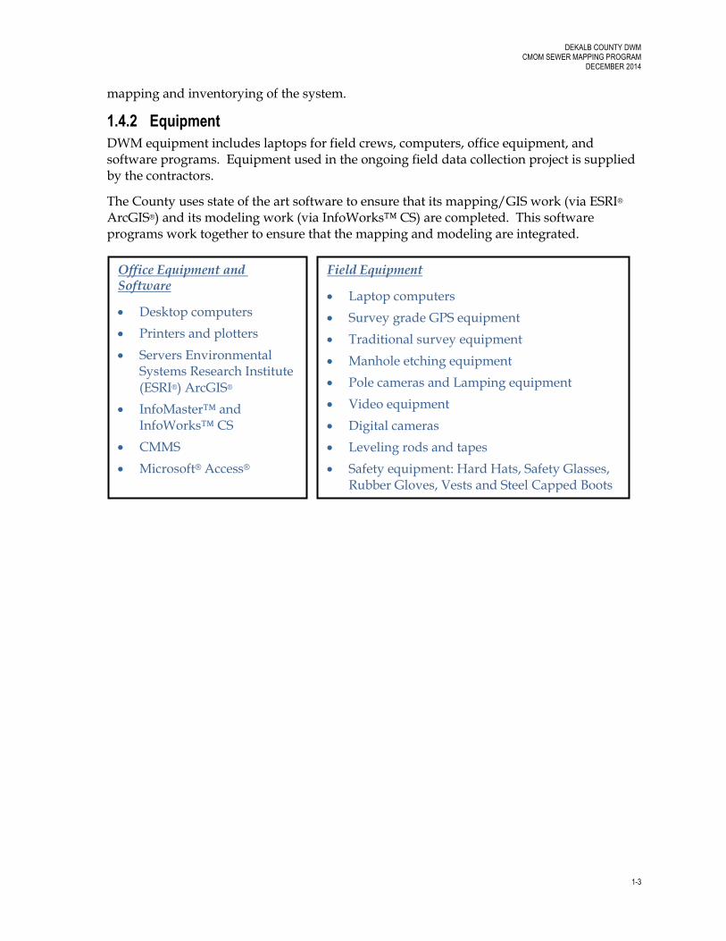
Office Equipment and Software
Desktop computers
Printers and plotters
Servers Environmental Systems Research Institute (ESRI®) ArcGIS®
InfoMaster™ and InfoWorks™ CS
CMMS
Microsoft® Access®
Field Equipment
Laptop computers
Survey grade GPS equipment
Traditional survey equipment
Manhole etching equipment
Pole cameras and Lamping equipment
Video equipment
Digital cameras
Leveling rods and tapes
Safety equipment: Hard Hats, Safety Glasses, Rubber Gloves, Vests and Steel Capped Boots
mapping and inventorying of the system.
1.4.2 Equipment
DWM equipment includes laptops for field crews, computers, office equipment, and software programs. Equipment used in the ongoing field data collection project is supplied by the contractors.
The County uses state of the art software to ensure that its mapping/GIS work (via ESRI®
ArcGIS®) and its modeling work (via InfoWorks™ CS) are completed. This software programs work together to ensure that the mapping and modeling are integrated.
DEKALB COUNTY DWM CMOM SEWER MAPPING PROGRAM
DECEMBER 2014
2-1
2. Program Implementation
2.1 Program Activities
DeKalb County has embarked on a system-wide Sewer Mapping Program using Global Positioning System (GPS) equipment and traditional survey methods to update sewer system GIS maps and component and asset inventory of the wastewater collection system.
The following are key aspects of, or functions included in, the Sewer Mapping Program:
Producing maps using GIS technology.
Electronic integration of sewer system location and attribute data with the County computer-based collection system hydraulic model and the computerized maintenance management systems (CMMS).
Producing maps showing the locations of all sanitary sewer manholes, gravity sewer pipes, lift stations, force mains, valves, and wastewater treatment facilities.
Producing maps capable of electronically integrating the locations of sewer service connections in pipes that have been televised and for which such electronic data identifying the precise GIS coordinates of the connections are provided. The context for gathering this electronic data shall be through the Priority Area Sewer Assessment and Rehabilitation Program (PASARP) and the Ongoing Sewer Assessment and Rehabilitation Program (OSARP). All non-emergency CCTV work done under the PASARP and OSARP will provide this precise electronic data which will then be available to DWM for electronic integration.
Producing maps that include attribute data for the County wastewater collection and transmission systems including, but not limited to, size, material, estimated age or age range, condition, slope, invert elevation, and rim elevation.
Producing maps that delineate the spatial boundaries of sewer basins and sewersheds.
Producing maps that can electronically integrate available maps, showing the location of surface streets and street addresses, surface water bodies, and political boundaries.
Reproducing maps in a manner that will allow use by all sewer system operation and maintenance crew leaders in the field.
Entry and mapping of work orders to identify and track problems geographically, such as stoppages, service interruptions, infiltration, and SSOs, and to assist in the planning, scheduling, and prioritization of maintenance.
Written standard operating procedures (SOPs) for use of sewer mapping, acquisition and entry of updated mapping data (for new assets or changes to existing assets), and updates to system software.
DEKALB COUNTY DWM CMOM SEWER MAPPING PROGRAM
DECEMBER 2014
2-2
A schedule for the completion of the electronic mapping and system inventory of the sewersheds in the wastewater collection and transmission system.
2.1.1 Asset Inventory and Mapping Summary
This section provides an overall summary of asset inventory and mapping, including information collected by the system mapping and inventory project (Section 2.1.3).A written procedure for Sewer Mapping is provided in Section 3 of this document, Program Procedures. Each asset will have a unique number for identification and tracking purposes.
2.1.1.1 Base Data
Service area boundaries and dimensions of landmarks such as surface streets, street addresses, surface water bodies, political boundaries, property lines, and Rights-of-Ways (ROWs) are created by the County’s GIS Department and are made available to DWM. DWM creates and maintains the utility easement, sewersheds, and sewershed basin maps.
2.1.1.2 Manholes
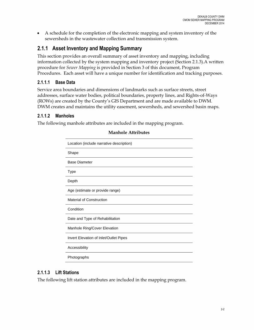
The following manhole attributes are included in the mapping program.
Manhole Attributes
Location (include narrative description)
Shape
Base Diameter
Type
Depth
Age (estimate or provide range)
Material of Construction
Condition
Date and Type of Rehabilitation
Manhole Ring/Cover Elevation
Invert Elevation of Inlet/Outlet Pipes
Accessibility
Photographs
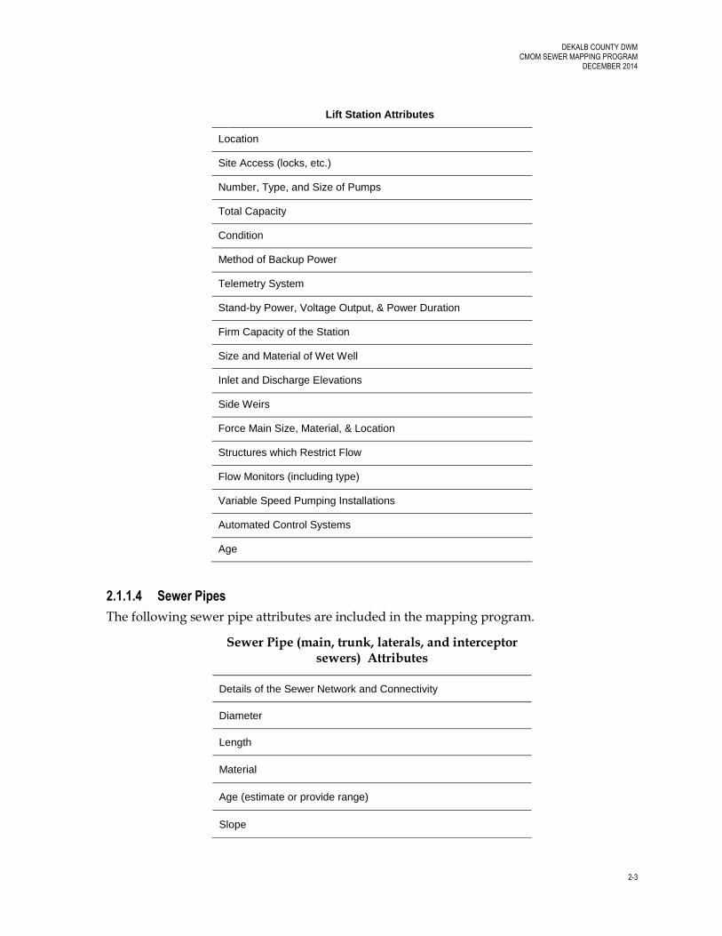
2.1.1.3 Lift Stations
The following lift station attributes are included in the mapping program.
DEKALB COUNTY DWM CMOM SEWER MAPPING PROGRAM
DECEMBER 2014
2-3
Lift Station Attributes
Location
Site Access (locks, etc.)
Number, Type, and Size of Pumps
Total Capacity
Condition
Method of Backup Power
Telemetry System
Stand-by Power, Voltage Output, & Power Duration
Firm Capacity of the Station
Size and Material of Wet Well
Inlet and Discharge Elevations
Side Weirs
Force Main Size, Material, & Location
Structures which Restrict Flow
Flow Monitors (including type)
Variable Speed Pumping Installations
Automated Control Systems
Age
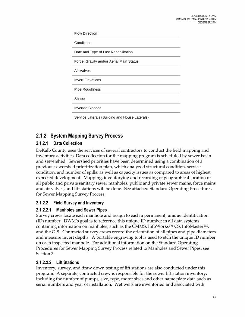
2.1.1.4 Sewer Pipes
The following sewer pipe attributes are included in the mapping program.
Sewer Pipe (main, trunk, laterals, and interceptor sewers) Attributes
Details of the Sewer Network and Connectivity
Diameter
Length
Material
Age (estimate or provide range)
Slope
DEKALB COUNTY DWM CMOM SEWER MAPPING PROGRAM
DECEMBER 2014
2-4
2.1.2 System Mapping Survey Process
2.1.2.1 Data Collection
DeKalb County uses the services of several contractors to conduct the field mapping and inventory activities. Data collection for the mapping program is scheduled by sewer basin and sewershed. Sewershed priorities have been determined using a combination of a previous sewershed prioritization plan, which analyzed structural condition, service condition, and number of spills, as well as capacity issues as compared to areas of highest expected development. Mapping, inventorying and recording of geographical location of all public and private sanitary sewer manholes, public and private sewer mains, force mains and air valves, and lift stations will be done. See attached Standard Operating Procedures for Sewer Mapping Survey Process.
2.1.2.2 Field Survey and Inventory
2.1.2.2.1 Manholes and Sewer Pipes Survey crews locate each manhole and assign to each a permanent, unique identification (ID) number. DWM’s goal is to reference this unique ID number in all data systems containing information on manholes, such as the CMMS, InfoWorks™ CS, InfoMaster™, and the GIS. Contracted survey crews record the orientation of all pipes and pipe diameters and measure invert depths. A portable engraving tool is used to etch the unique ID number on each inspected manhole. For additional information on the Standard Operating Procedures for Sewer Mapping Survey Process related to Manholes and Sewer Pipes, see Section 3.
2.1.2.2.2 Lift Stations Inventory, survey, and draw down testing of lift stations are also conducted under this program. A separate, contracted crew is responsible for the sewer lift station inventory, including the number of pumps, size, type, motor sizes and other name plate data such as serial numbers and year of installation. Wet wells are inventoried and associated with
Flow Direction
Condition
Date and Type of Last Rehabilitation
Force, Gravity and/or Aerial Main Status
Air Valves
Invert Elevations
Pipe Roughness
Shape
Inverted Siphons
Service Laterals (Building and House Laterals)

DEKALB COUNTY DWM CMOM SEWER MAPPING PROGRAM
DECEMBER 2014
2-5
dimensions, location by street address, subdivision, and drainage sewershed. Contractor survey crews record horizontal and vertical coordinates of manholes, lift stations, and property boundary survey. For additional information on the Standard Operating Procedures related to Lift Stations, see Section 3.
2.1.2.3 Data Submission
As the field teams complete the location survey of each sewershed, the contractor delivers a database containing the records of all assets surveyed and a Technical Memorandum to the contract administrator containing the following:
Description of inventory and quality control processes and database structure, attributes, and available reports
Environmental Systems Research Institute (ESRI®) ArcGIS® depicting the location of sewer manholes, sewer pipes (including diameter and flow direction) and lift stations
DWM uses the ESRI® ArcGIS® for mapping and for system inventory. Data is received from the mapping project by the DWM GIS Manager and imported into other software systems, as applicable.
In addition, GIS staff import feature locations and attributes from the delivered GIS file databases into the central GIS. Data submission for new development sewer assets are incorporated into the GIS based on digital submission standards required for developer drawings. A written procedure for updating maps with new assets is included in Section 3, see attached Standard Operating Procedure for Updating the Sanitary Sewer GIS Inventory. In addition, related CMOM program include the DWM CMOM Infrastructure Acquisition Program (2012).
2.1.2.4 Inventory Completion
Attributes that could not be directly obtained through field survey will be completed later by processing the data obtained in the field and historical record by contractors or DWM staff. For example, date and type of rehabilitation will be completed based on DWM’s records; pipe slope will be determined based on the upstream and downstream pipe inverts and pipe length (by field surveyed upstream and downstream manhole coordinates); pipe age will be estimated based on information sources such as plat and as-built records for pipe installations and pipe material where could be observed from field surveys, etc.
2.1.3 Data Updates
In addition to data from the system mapping and inventory survey, data updates to the system will derive from (1) new developments that are depicted on a final plat or as-built (survey data); (2) system changes that have been reported by DeKalb County personnel in the regular course of business; and (3) system changes that have been reported by non-DeKalb County personnel. All DWM personnel have access to all GIS maps DWM creates. Similarly, field superintendents have access to all GIS maps DWM creates of the sanitary sewer collection system on laptop computers for use in the field. The GIS drawings are separated and color coded into “verified” and “unverified” feature levels, the “verified” having been added from the field locates taken since the beginning of the mapping program. Field personnel without laptops print hard copy maps from the GIS. Any map
DEKALB COUNTY DWM CMOM SEWER MAPPING PROGRAM
DECEMBER 2014
2-6
errors noted are recorded and returned to the GIS manager or the GIS specialist for GIS map revisions. Maps include date drafted and date of last update. Separate, detailed local maps are also available to field crews. Field laptops are given access to a departmental ArcOnline account for mobile access to the GIS. See the Standard Operating Procedures in Section 3 for information on how the DWM incorporates data updates into the system.
2.1.4 Geographic Tracking of System Problems
The technology integration process (between the CMMS system, InfoMaster software, and GIS) that is currently underway will enable DeKalb County to identify and track problems geographically. When work orders are written identifying stoppages, service interruptions, infiltration, and SSOs, the locations of problems can be viewed within the GIS. After work is completed on assets within the CMMS, the condition and/or risk can be updated within the GIS and reflected within InfoMaster.. The InfoMaster database also contain CCTV results, asset inventory information, sewer evaluations, and smoke testing data. The information in the database is then used by the modeling tool (InfoWorks™ CS) to project other potential “trouble spots” on the system. The InfoWorks™ CS modeling and the InfoMaster™ databases can then be used by the Engineering and Asset Management staff to assist in the planning, scheduling, and prioritization of system maintenance. These projected “trouble spots” and the corresponding modeled information will then be turned over to the C&M staff to evaluate and decide whether to enter new proactive maintenance work orders.
DEKALB COUNTY DWM CMOM SEWER MAPPING PROGRAM
DECEMBER 2014
2-7
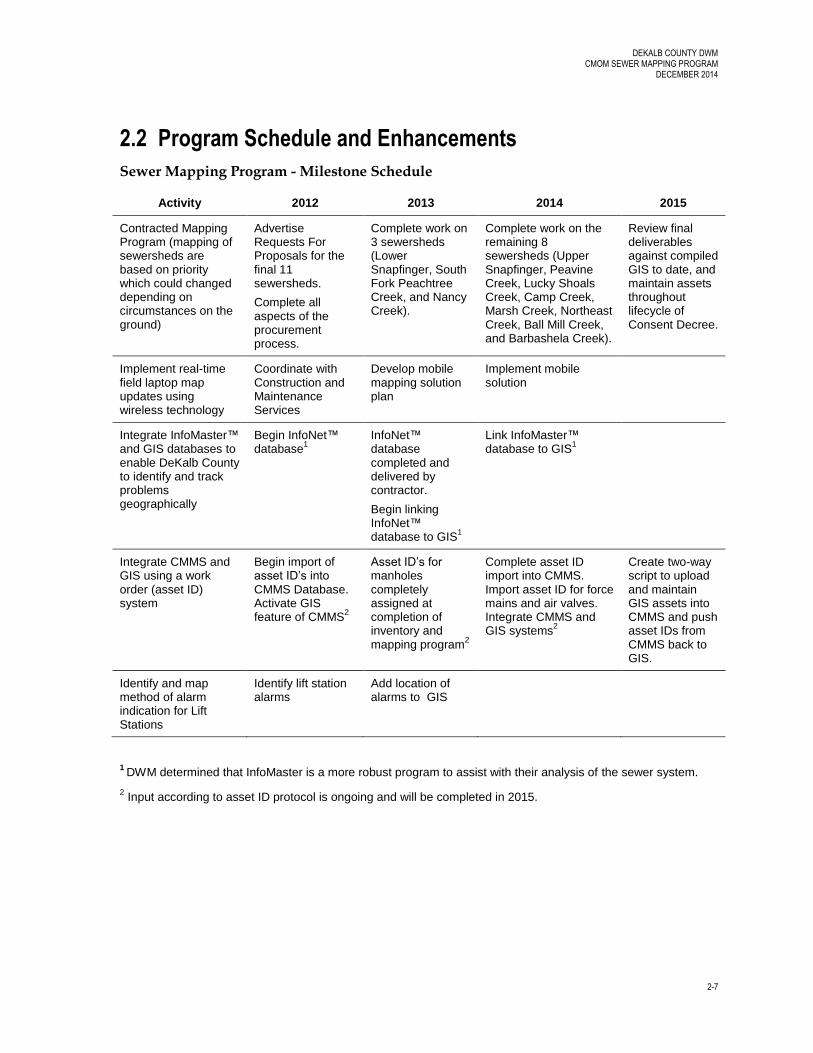
2.2 Program Schedule and Enhancements
Sewer Mapping Program - Milestone Schedule
Activity 2012 2013 2014 2015
Contracted Mapping Program (mapping of sewersheds are based on priority which could changed depending on circumstances on the ground)
Advertise Requests For Proposals for the final 11 sewersheds.
Complete all aspects of the procurement process.
Complete work on 3 sewersheds (Lower Snapfinger, South Fork Peachtree Creek, and Nancy Creek).
Complete work on the remaining 8 sewersheds (Upper Snapfinger, Peavine Creek, Lucky Shoals Creek, Camp Creek, Marsh Creek, Northeast Creek, Ball Mill Creek, and Barbashela Creek).
Review final deliverables against compiled GIS to date, and maintain assets throughout lifecycle of Consent Decree.
Implement real-time field laptop map updates using wireless technology
Coordinate with Construction and Maintenance Services
Develop mobile mapping solution plan
Implement mobile solution
Integrate InfoMaster™ and GIS databases to enable DeKalb County to identify and track problems geographically
Begin InfoNet™ database
1
InfoNet™ database completed and delivered by contractor.
Begin linking InfoNet™ database to GIS
1
Link InfoMaster™ database to GIS
1
Integrate CMMS and GIS using a work order (asset ID) system
Begin import of asset ID’s into CMMS Database. Activate GIS feature of CMMS
2
Asset ID’s for manholes completely assigned at completion of inventory and mapping program
2
Complete asset ID import into CMMS. Import asset ID for force mains and air valves. Integrate CMMS and GIS systems
2
Create two-way script to upload and maintain GIS assets into CMMS and push asset IDs from CMMS back to GIS.
Identify and map method of alarm indication for Lift Stations
Identify lift station alarms
Add location of alarms to GIS
1 DWM determined that InfoMaster is a more robust program to assist with their analysis of the sewer system.
2 Input according to asset ID protocol is ongoing and will be completed in 2015.
3-1
3. Program Procedures
DWM Procedures for the Sewer Mapping Program have been developed to ensure that the mapping of the DeKalb County Sewer System is compliant with the County’s legal obligations. The procedures have been developed to document a process by which DWM conducts specific program elements.
Written procedures for updating maps with new assets are provided in the DeKalb DWM CMOM Infrastructure Acquisition Program (2012).
Sewer Mapping Program procedures are provided in this Section and include:
The Standard Operating Procedure for the Sewer Mapping Survey Process
The Standard Operating Procedure for Updating the Sanitary Sewer GIS Inventory
The Standard Operating Procedure for Using the Sanitary Sewer GIS Inventory
The Standard Operating Procedure for Updating the GIS Software
Department of Watershed Management
STANDARD OPERATING PROCEDURES
3-2
3.1 Sewer Mapping Survey Process
SCHEDULE
Schedule based on areas identified by Program Manager of Mapping Program.
ACTIVITY DESCRIPTION
Procedure defines mapping activities for field crews and data management activities for GIS Specialists.
ACTIVITY GOALS
To accurately identify assets in the field using GPS equipment and upload data into GIS database.
LABOR MATERIAL and EQUIPMENT
Assistant Director, Engineering and Technical Services GIS Manager GIS Specialists Contract personnel that conduct field surveys Contract personnel who perform data management
Laptop computers Traditional and Survey grade GPS equipment Manhole etching equipment Digital cameras Leveling rods and tapes Safety equipment: Hard hat, Safety glasses, Rubber gloves, Vests and Steel capped boots
SAFETY ANALYSIS
Safety Check List Potential Hazards
Collection and Transmission Systems Safety Program Plan Traffic Safety Requirements
Infectious Diseases Slip, Trip, and Fall Snakes, Pests, Insects Confined Space Entry (not applicable, field crews are not entering confined space) Traffic Vehicle Operation Electrical Hazards (Electrical Safety) Lifting
Mapping Procedures for Manholes and Sewer Pipes DWM has contracted the mapping of the sewer collection system. Contractors gather asset location in
the field and transmit the data in digital and hard copy format to DWM for integration into existing
systems. Deliverables for each basin/sewershed include digital photos of manholes, access database,
map books and a Technical Memorandum. DWM staff from the Engineering and Technical Services
Divisions are involved in quality control and integrating the information into the existing GIS and the
CMMS.
Department of Watershed Management
STANDARD OPERATING PROCEDURES
3-3
1) Existing maps are used as a starting point to assist survey crews in locating sewer features and to
be marked up where errors are found during field verification.
2) Survey crews are sent out to collect horizontal and vertical coordinates for each manhole with GPS
or conventional survey equipment, and collect attributes information and record the data on survey
forms that will be used to correct the field maps. The attribute data for manholes are to include, at a
minimum: Location (include narrative description), Shape, Base Diameter, Type, Depth, Age
(estimate or provide range), Material of Construction, Condition, Date and Type of Rehabilitation,
Manhole Ring/Cover Elevation, Invert Elevation of Inlet/Outlet Pipes, Accessibility, and
Photographs. The attribute data for sewer pipes are to include, at a minimum: Details of the Sewer
Network and Connectivity, Diameter, Length, Material, Age (estimate or provide range), Slope, Flow
Direction, Condition, Date and Type of Last Rehabilitation, Force, Gravity and/or Aerial Main Status,
Air Valves, Invert Elevations, Pipe Roughness, Shape, Inverted Siphons, and Service Laterals
(Building and House Laterals).
3) Field maps are also corrected with red-line edits. The orientation of all incoming and outgoing
pipes is recorded relative to north.
4) Working one sewershed at a time, the contractor performs the initial data collection and a quality
review by re-inspecting 2 percent of the manholes found.
5) DWM issues internal work orders to locate any manholes noted as buried or not located.
6) DWM completes quality checks and returns questionable data to the contractor for verification.
7) The contractor enters the new asset information in a file database (ESRI file or personal database).
The database contains survey coordinates and elevations of manholes, invert elevations, material,
diameter of incoming and outgoing pipes, and digital photos. The first draft of the model is quality
checked, corrected and delivered by the contractor to DWM as an ESRI file database. DWM
conducts further reviews of the data prior to final acceptance.
Mapping Procedures for Sewer Lift Stations 1) The attribute data for lift stations are to include, at a minimum: Location, Site Access (locks, etc.),
Number, Type, and Size of Pumps, Total Capacity, Condition, Method of Backup Power, Telemetry
System, Stand-by Power, Voltage Output, & Power Duration, Firm Capacity of the Station, Size and
Material of Wet Well, Inlet and Discharge Elevations, Side Weirs, Force Main Size, Material, &
Location, Structures which Restrict Flow, Flow Monitors (including type), Variable Speed Pumping
Installations, Automated Control Systems, and Age.
2) In addition, the contractor performs survey of lift station wet well, vault chambers, standby
generators, fencing, and storm water structures. Measurements are made of wet well dimensions
and the elevations of level controls. All data is recorded on the “Appendix C - Lift Station Inspection
Form – DeKalb Mapping Project”.
3) Contractor performs draw down tests, collects nameplate data and enters data on the inspection
form. A flow monitor is installed and collected at least 2 days later. Contractor analyzes flow
monitor data, pump draw down curves are prepared, and data is entered into an Access database.
4) Survey crews collect horizontal coordinates for the corners of structures, including buildings and
fences, and elevations of the top of structures.
5) Contractor updates ESRI file database and technical memorandum and electronic deliverables are
delivered to DWM.
Department of Watershed Management
STANDARD OPERATING PROCEDURES
3-4
3.2 Updating the Sanitary Sewer GIS Inventory
The process for integrating new data into the GIS follows a three-step process of:
1. Data Input and Formatting,
2. File Incorporation, and
3. Quality Control.
Data Input and Formatting New data that will be used to update the sanitary sewer GIS inventory originate from four sources:
1. New developments that are depicted on a final plat or as-built (survey data).
2. Surveys of the existing system by contractors/third parties or DeKalb County personnel.
3. System changes that have been reported by DeKalb County personnel in the regular course of
business (with no survey available).
4. System changes that have been reported by non-DeKalb County personnel (with no survey
available).
The data input process and formatting of the data for each of the data source is as follows:
a. New additions from development with final plat or as-built
i. The DWM requires a copy of a final plat or as-built of the new development. The
Department’s current design standards require that these documents be in digital format,
preferably a GIS or CAD file. However, if a digital file of the final plat is not available of the
final plat one can be created by scanning the hardcopy and creating a digital file in a
format readable by ArcMap.
ii. Upon receipt of one of these final plans of a new development, the GIS Engineering
Supervisor will assign GIS personnel to input the final plan into the Department’s sanitary
sewer GIS inventory. The input process is as follows:
1. Step 1 (a) – View the digital file in ESRI ArcMap GIS program to ensure that the
plan is in the correct State Plane coordinate system for DeKalb County as required
by the standards and need no further manipulation or managing.
2. Step 1 (b) – Hardcopy files that are scanned into a digital file in a format readable
by ArcMap, must be moved to the correct location in the County using coordinates
from the plan or by using common features in both the GIS and the plan. Match
the scanned drawing to edge of pavement or existing landmarks to place the
drawing in the correct orientation in the GIS.
3. Step 2 – The GIS personnel assigned to input the new data will begin adding (1)
actual structures (such as manholes, pipes, lift stations etc.) and (2) attributes
(such as invert elevation, ground elevation, location, slope of pipe, material, size,
construction date, length, and nearest address to the existing inventory) using
ESRI tools for editing and creating.
Department of Watershed Management
STANDARD OPERATING PROCEDURES
3-5
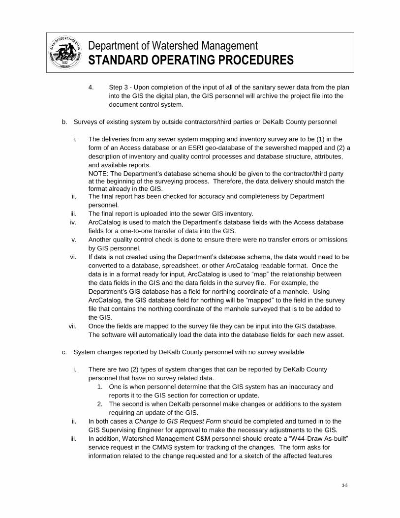
4. Step 3 - Upon completion of the input of all of the sanitary sewer data from the plan
into the GIS the digital plan, the GIS personnel will archive the project file into the
document control system.
b. Surveys of existing system by outside contractors/third parties or DeKalb County personnel
i. The deliveries from any sewer system mapping and inventory survey are to be (1) in the
form of an Access database or an ESRI geo-database of the sewershed mapped and (2) a
description of inventory and quality control processes and database structure, attributes,
and available reports.
NOTE: The Department’s database schema should be given to the contractor/third party at the beginning of the surveying process. Therefore, the data delivery should match the format already in the GIS.
ii. The final report has been checked for accuracy and completeness by Department
personnel.
iii. The final report is uploaded into the sewer GIS inventory.
iv. ArcCatalog is used to match the Department’s database fields with the Access database
fields for a one-to-one transfer of data into the GIS.
v. Another quality control check is done to ensure there were no transfer errors or omissions
by GIS personnel.
vi. If data is not created using the Department’s database schema, the data would need to be
converted to a database, spreadsheet, or other ArcCatalog readable format. Once the
data is in a format ready for input, ArcCatalog is used to “map” the relationship between
the data fields in the GIS and the data fields in the survey file. For example, the
Department’s GIS database has a field for northing coordinate of a manhole. Using
ArcCatalog, the GIS database field for northing will be “mapped” to the field in the survey
file that contains the northing coordinate of the manhole surveyed that is to be added to
the GIS.
vii. Once the fields are mapped to the survey file they can be input into the GIS database.
The software will automatically load the data into the database fields for each new asset.
c. System changes reported by DeKalb County personnel with no survey available
i. There are two (2) types of system changes that can be reported by DeKalb County
personnel that have no survey related data.
1. One is when personnel determine that the GIS system has an inaccuracy and
reports it to the GIS section for correction or update.
2. The second is when DeKalb personnel make changes or additions to the system
requiring an update of the GIS.
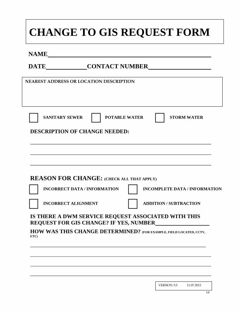
ii. In both cases a Change to GIS Request Form should be completed and turned in to the
GIS Supervising Engineer for approval to make the necessary adjustments to the GIS.
iii. In addition, Watershed Management C&M personnel should create a “W44-Draw As-built”
service request in the CMMS system for tracking of the changes. The form asks for
information related to the change requested and for a sketch of the affected features
Department of Watershed Management
STANDARD OPERATING PROCEDURES
3-6
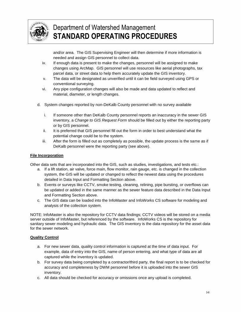
and/or area. The GIS Supervising Engineer will then determine if more information is
needed and assign GIS personnel to collect data.
iv. If enough data is present to make the changes, personnel will be assigned to make
changes using ArcMap. GIS personnel will use resources like aerial photographs, tax
parcel data, or street data to help them accurately update the GIS inventory.
v. The data will be designated as unverified until it can be field surveyed using GPS or
conventional surveying.
vi. Any pipe configuration changes will also be made and data updated to reflect and
material, diameter, or length changes.
d. System changes reported by non-DeKalb County personnel with no survey available
i. If someone other than DeKalb County personnel reports an inaccuracy in the sewer GIS
inventory, a Change to GIS Request Form should be filled out by either the reporting party
or by GIS personnel.
ii. It is preferred that GIS personnel fill out the form in order to best understand what the
potential change could be to the system.
iii. After the form is filled out as completely as possible, the update process is the same as if
DeKalb personnel were the reporting party (see above).
File Incorporation Other data sets that are incorporated into the GIS, such as studies, investigations, and tests etc.:
a. If a lift station, air valve, force main, flow monitor, rain gauge, etc. is changed in the collection
system, the GIS will be updated or changed to reflect the newest data using the procedures
detailed in Data Input and Formatting Section above.
b. Events or surveys like CCTV, smoke testing, cleaning, relining, pipe bursting, or overflows can
be updated or added in the same manner as the sewer feature data described in the Data Input
and Formatting Section above.
c. The GIS data can be loaded into the InfoMaster and InfoWorks CS software for modeling and
analysis of the collection system.
NOTE: InfoMaster is also the repository for CCTV data findings; CCTV videos will be stored on a media server outside of InfoMaster, but referenced by the software. InfoWorks CS is the repository for sanitary sewer modeling and hydraulic data. The GIS inventory is the data repository for the asset data for the sewer network. Quality Control
a. For new sewer data, quality control information is captured at the time of data input. For
example, data of entry into the GIS, name of person entering, and what type of data are all
captured while the inventory is updated.
b. For survey data being completed by a contractor/third party, the final report is to be checked for
accuracy and completeness by DWM personnel before it is uploaded into the sewer GIS
inventory.
c. All data should be checked for accuracy or omissions once any upload is completed.

Department of Watershed Management
STANDARD OPERATING PROCEDURES
3-7
d. In addition, a final quality control check will be done at the end of the entire data input,
formatting, and integration process to check for errors or omissions.
Department of Watershed Management
STANDARD OPERATING PROCEDURES
3-8
NAME
DATE CONTACT NUMBER
UTILITY THAT NEEDS CHANGE: (CHECK ALL THAT APPLY)
DESCRIPTION OF CHANGE NEEDED:
REASON FOR CHANGE: (CHECK ALL THAT APPLY)
IS THERE A DWM SERVICE REQUEST ASSOCIATED WITH THIS
REQUEST FOR GIS CHANGE? IF YES, NUMBER
HOW WAS THIS CHANGE DETERMINED? (FOR EXAMPLE, FIELD LOCATED, CCTV,
ETC)
CHANGE TO GIS REQUEST FORM
SANITARY SEWER POTABLE WATER STORM WATER
INCORRECT DATA / INFORMATION
INCORRECT ALIGNMENT
INCOMPLETE DATA / INFORMATION
ADDITION / SUBTRACTION
NEAREST ADDRESS OR LOCATION DESCRIPTION
VERSION 3.0 11.07.2012
Department of Watershed Management
STANDARD OPERATING PROCEDURES
3-9
3.3 Using the Sanitary Sewer GIS Inventory
The DeKalb County Department of Watershed Management (DWM) maintains a Geographic Information System (GIS) inventory of its sanitary sewer collection system for use by County employees. Employees can access the GIS inventory through (1) the ESRI software (ArcInfo, ArcMap and ArcGIS), (2) Adobe software, or (3) the County’s intranet resource. However, employees have different permission levels to access the GIS inventory based on their job type and level of responsibility. The levels of GIS interaction are administrator, editor, or viewer.
a. Administrators have the ability to manage the ESRI server and the files located there. They
have ArcGIS server software or ArcInfo software licenses. The number of administrators is
small with only two copies of ArcInfo available.
b. Editors have access to ArcMap and are able to create feature sets, shape files, geo-databases,
edit data, create or delete records in the inventory, and create custom maps.
c. Viewers have only the ability to view the data, print maps, and turn layers on or off. Viewers
can access the GIS through the intranet via Flex software, the ESRI server via their personal
computer or field personnel viewers have access to GIS PDF files through Adobe Reader
software.
Administrators are responsible for managing the data on the server and maintaining the data as a whole. They resolve errors or software problems and are responsible for posting, or uploading, changes to the GIS after edits have been made. They are responsible for managing the ArcGIS for Flex site and for any changes that need to be made to it. They perform troubleshooting on desktop applications and are in charge of data organization and standards. Editors perform the production part of the GIS. They create datasets and geo-databases whenever a new type of data is produced. Most of their time is spent adding data to the various feature sets and databases in ArcMap. They are able to query the data and do analysis. They are able to change the way the map is presented and are able to print custom maps. Editors can create subsets of data based on location or attribute data. They are constantly maintaining the data as updates and additions are delivered. Viewers use the ArcGIS for Flex site through the intranet or the ArcOnline departmental account through the internet Viewers can be in any department in the County.
a. In general, viewers are able to turn the water, sewer, and storm water utility maps on or off in
Flex. They can toggle between a base map of streets and buildings, aerial photographs, or a
base map with topographic lines shown. They have the ability to search for an address,
measure on the map, add text or draw on the map, and print what is shown on the screen.
Viewers however, do not have the ability to customize this data like editors do.
Department of Watershed Management
STANDARD OPERATING PROCEDURES
3-10
b. Field personnel with laptops have the ability to access the GIS maps through departmental
ArcOnline account. They also have the ability to turn layers on or off. There is limited data
associated with the features on the map as well.
The only restriction to who can view the data is through access to the network. Administrators maintain access privileges and rights to data. As the need for more access to functionality higher than that of a viewer becomes greater, the ability to limit user’s access to editing data will increase. This will allow users to have the same analysis and map making abilities of editors without the ability to change the data. Expanding and use of the GIS comes through the Engineering Services Director and Assistant Director of Engineering and Asset Management. The GIS manager supervises and directs the administrators and editors. The GIS Manager and designated engineer of DWM will be the administrators responsible for managing the ESRI server and data files: GIS Manager Phone: 770-621-7214 Email: [email protected] GIS Engineer Phone: 770-621-7297 Email: [email protected]
Department of Watershed Management
STANDARD OPERATING PROCEDURES
3-11
3.4 Updating the GIS Software
The software programs currently being utilized by the Department of Watershed Management (DWM) GIS Section are ESRI, ArcGIS server, ArcInfo, ArcMap, and ArcGIS viewer for Flex. Bentley Systems, Inc. Microstation v8, software is used for engineering drawings and CAD drawing production. All of these software packages are maintained by DeKalb County’s Information Systems Department and are housed on servers at the Watershed Department’s facility. While DWM reserves the right in its sole discretion to change, update or replace these software, DWM uses these software programs to update, maintain, and manage the sanitary sewer GIS inventory databases. The procedure for updating the software is coordinated through the County’s Information Systems (IS) Department as follows: 1) The end user (primarily the GIS Manager) typically gets a notification from the vendor that a patch,
new version, or upgrade is available. The GIS Manager and IS Manager will evaluate the need for
this patch, new version, or upgrade based on business drivers. If there is a need for the product,
the GIS Manager and IS Manager will assemble a project team to participate in the implementation
process (the size of the team depends on the impact of the patch, new version, or upgrade on the
current system).
2) The business drivers and examples include:
a) Significant application enhancements from the current version
For example, if the new version of the software could drastically improve the performance
comparing to the current version, or the new patches could eliminate more bugs, etc.
b) Software technical specifications
For example, if the new version has the latest operating system, better Geographical User
Interface (GUI), or it is more compatible with other hardware and/or software that currently used
by DWM, such as InfoWorksTM
CS for hydraulic modeling.
c) Technical support expiring for the current version
The vendor has a timeline to provide technical support to the current version, or if free technical support and training are offered for the upgraded version, etc.
3) The project team
a) Identifies the project goals
b) Provides a project description/end product
c) Determines what functional area would be affected by the software changes
d) Establishes a desired implementation date
4) In addition, personnel in the IS department evaluates the software changes to see what would be
impacted.
Department of Watershed Management
STANDARD OPERATING PROCEDURES
3-12
5) The GIS manager or the IS manager submits an IS Maintenance Request that initiates the
purchasing process. The project team then determines the scope of the product and a manager
submits a Purchase Order to the vender.
6) Once the software update has been acquired and delivered to the IS department, the IS department
in conjunction with DWM will formulate a plan for updating the software that reduces interruption of
service and downtime.
7) IS backups all data before updating.
8) IS runs the patch/new version/upgrade of the software in parallel to the existing software if possible.
9) IS tests and configures the software to minimize a loss in the functionality of the existing software.
10) At the completion of testing, IS converts users to the new version. This includes updating shortcuts
or icons, links to folders, and filenames. The IS department will do some of this remotely when the
software is updated.
11) An internal training session takes place during the upgrade process. Training is either provided by
the software vendor or a consultant.
DEKALB COUNTY DWM CMOM SEWER MAPPING PROGRAM
DECEWMBER 2014
Appendices
Appendix A - Request for Proposal - Geographical Location and Inventory of the Wastewater Collection System
Appendix B – Sewershed Map –Mapping Completed, to be Completed in 2013, and in 2014
Appendix C – Lift Station Inspection Form – DeKalb Mapping Project

DEKALB COUNTY DWM CMOM SEWER MAPPING PROGRAM
DECEWMBER 2014
A-1
Appendix A
Scope of Geographical Location and Inventory of the Wastewater Collection System
DEKALB COUNTY DWM CMOM SEWER MAPPING PROGRAM
DECEWMBER 2014
A-2
Scope of Geographical Location and Inventory of the Wastewater Collection System
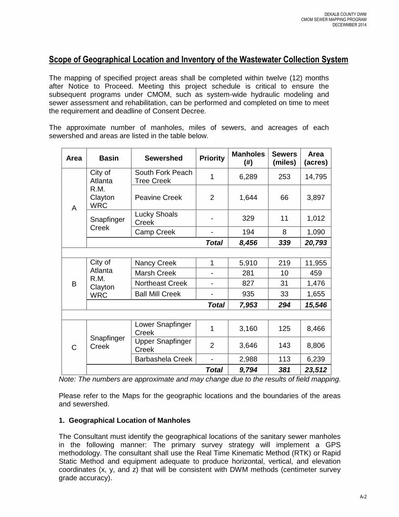
The mapping of specified project areas shall be completed within twelve (12) months after Notice to Proceed. Meeting this project schedule is critical to ensure the subsequent programs under CMOM, such as system-wide hydraulic modeling and sewer assessment and rehabilitation, can be performed and completed on time to meet the requirement and deadline of Consent Decree.
The approximate number of manholes, miles of sewers, and acreages of each sewershed and areas are listed in the table below.
Area Basin Sewershed Priority Manholes
(#) Sewers (miles)
Area (acres)
A
City of Atlanta R.M. Clayton WRC
South Fork Peach Tree Creek
1 6,289 253 14,795
Peavine Creek 2 1,644 66 3,897
Snapfinger Creek
Lucky Shoals Creek
- 329 11 1,012
Camp Creek - 194 8 1,090
Total 8,456 339 20,793
B
City of Atlanta R.M. Clayton WRC
Nancy Creek 1 5,910 219 11,955
Marsh Creek - 281 10 459
Northeast Creek - 827 31 1,476
Ball Mill Creek - 935 33 1,655
Total 7,953 294 15,546
C
Snapfinger Creek
Lower Snapfinger Creek
1 3,160 125 8,466
Upper Snapfinger Creek
2 3,646 143 8,806
Barbashela Creek - 2,988 113 6,239
Total 9,794 381 23,512
Note: The numbers are approximate and may change due to the results of field mapping.
Please refer to the Maps for the geographic locations and the boundaries of the areas and sewershed. 1. Geographical Location of Manholes
The Consultant must identify the geographical locations of the sanitary sewer manholes in the following manner: The primary survey strategy will implement a GPS methodology. The consultant shall use the Real Time Kinematic Method (RTK) or Rapid Static Method and equipment adequate to produce horizontal, vertical, and elevation coordinates (x, y, and z) that will be consistent with DWM methods (centimeter survey grade accuracy).
DEKALB COUNTY DWM CMOM SEWER MAPPING PROGRAM
DECEWMBER 2014
A-3
If it is determined that a number of features cannot be located directly by GPS due to tree canopy or large buildings or any other reasons, a secondary survey will be employed to capture obscured points.
The secondary strategy should consist of surveying using conventional methods. Ths would include establishing a transit and back sight using GPS, establishing a traverse loop, maintaining a minimum of 1:10,000 closure for the traverse, and side shots being collected by occupying the traverse points. The side shot should be enough to adequately survey the required features and/or other relevant features. After data collection is complete, standard survey procedure dictates that the files will be downloaded into a Coordinate Geometry (COGO) package for any translation or rotation that might be required, and the specifications for the datum and coordinate will be the Georgia West State Plane coordinate system North American Datum (NAD83) and North American Vertical Datum (NAVD88).
The Consultant may encounter the situation that some of the manholes are in easements which are difficult to access. The Consultant shall clear the easements at its own expense for minimum physical access of personnel and equipment. The Consultant shall at all times abide by County, State and Federal regulations and obtain the necessary permits if required. The County is not responsible for clearing of easements for mapping purposes, or for obtaining any City, County, State or Federal permits for the clearing operations.
2. Inventory Database of Manholes
The Consultant shall obtain the following information for the Wastewater Collection System manhole inventory: horizontal, vertical, and elevation coordinates, invert elevations and diameters for all pipes in and out of the manhole, size of the manhole, type of construction material, location by street address and name of subdivision if possible, basin and sewershed. DWM will provide manhole identification numbers and approximate Northing and Easting. The manhole numbers should be etched on the ring around the cover. Minimum two digital photos should be taken, including a manhole location photo showing manhole and etched ID number as well as surrounding streets and buildings, and a top view photo showing the sewer path, in and out pipes, and flow conditions. A schematic shall also be provided for each manhole indicating the configuration of all incoming and outgoing pipes. All manhole condition shall be documented, including any major structure defects which may cause inflow and infiltration, blockage due to fat, oil, and grease as well as debris and roots. Additional photos shall be taken as needed to show the problems. The Consultant shall survey all manholes on the sewer mains that found in the field, not just the manholes included in the County’s existing inventory. All manholes in the private sewer systems within the County will be surveyed in the same manner as the County’s public sewer system.
3. Inventory Database of Sewer Mains
The sewer mains defined under this RFP include all gravity sewer lines and force mains
within the project sewershed.
DEKALB COUNTY DWM CMOM SEWER MAPPING PROGRAM
DECEWMBER 2014
A-4
The Consultant shall obtain the following information for the Wastewater Collection
System sewer main inventory database: basin, sewershed, subdivision if possible, street
name, upstream and downstream manhole ID numbers, upstream and downstream
inverts, type of material, diameter, dimensions and shape if the sewer is not a round
pipe, brief pipe conditions and any problems including deformation, broken pipe, missing
piece, offset joints, and blockages from fats, oils, and grease as well as debris and roots.
Minimum two photos shall be taken at each manhole location, including section view
photos for in and out pipes showing the pipe and flow conditions. Additional photos shall
be taken if any problem presents.
4. Inventory Database QA/QC
The Consultant shall perform data QA/QC during the field survey and prior to submit the database to the County. The data QA/QC shall include but not limit to:
Ensure there is no manhole missing from survey according to the inventory
provided by the County.
The Consultant shall report to the County that if there are any buried manholes or
manholes that enable to survey, prior to the completion of sewershed survey.
Ensure that there will be no missing data for manholes and sewer mains required
under this RFP.
Ensure the accuracy of coordinates, invert, and rim elevation of manholes.
Ensure the accuracy of all pipe size, material, shape, and inverts.
Check sewer pipe size from upstream manhole versus to downstream manhole to
ensure the consistency of pipe size.
Check the pipe sizes between upstream and downstream sections. If the
downstream pipe section has a smaller diameter, it is possible that a wrong
manhole was surveyed.
Check the invert of upstream manhole outlet pipe versus invert of downstream
manhole inlet pipe, flag any of the gravity sewer mains with upstream invert is
equal or lower than the downstream invert.
The database provided by the Consultant shall be accurate for building the
County’s computer-based collection system model to comply with the pending
Consent Decree.
5. Inventory Database Format
The inventory database shall be submitted as an ESRI shape file or geo-database
with each feature represented in a different feature class (manholes, mains, etc.).
The data must be in the correct datum system as specified under Section 1 and able
to be integrated into County’s ESRI ARCGIS system which is the County’s standard
GIS software. Oracle is the County’s standard database software.

B-1
Appendix B
Sewershed Map – Mapping Completed, to be Completed in 2013, and in 2014
B-2

C-1
Appendix C
Lift Station Inspection Form – DeKalb Mapping Project
C-2
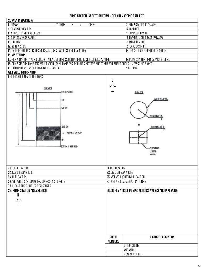
PUMP STATION INSPECTION FORM – DEKALB MAPPING PROJECT
SURVEY INSPECTION:
1. CREW: 2. DATE: / / TIME: 3. PUMP STATION ID/NAME:
4. GENERAL LOCATION: 5. LAND LOT:
6. NEAREST STREET ADDRESS: 7. DRAINAGE BASIN:
8. SUB-DRAINAGE BASIN: 9. OWNER (1. COUNTY, 2. PRIVATE):
10. COUNTY: 11. MUNICIPALITY:
12. SUBDIVISION: 13. LAND DISTRICT:
14. TYPE OF FENCING - CODES (1. CHAIN LINK 2. WOOD 3. BRICK 4. NONE): 15. FENCE PERIMETER/LENGTH (FEET):
PUMP STATION
16. PUMP STATION TYPE – CODES ( 1. ABOVE GROUND 2. BELOW GROUND 3. RECESSED 4. NONE): 17. PUMP STATION FIRM CAPACITY (GPM):
18. PUMP STATION NAME TAG VERIFICATION (SAME NAME TAG ON PUMPS, MOTORS AND OTHER EQUIPMENT-CODES ( 1. YES 2. NO & WHY):
19. CENTER OF WET WELL COORDINATES: EASTING: NORTHING:
WET WELL INFORMATION
RECORD ALL 5 MEASURE DOWNS
N
20. TOP ELEVATION: 21. HH ELEVATION:
22. LAG ON ELEVATION: 23. LEAD ON ELEVATION:
24. LL ELEVATION: 25. WET WELL (BOTTOM) ELEVATION:
26. WET WELL SIZE (DIAMETER/DIMENSIONS IN FEET): 27. WET WELL CAPACITY, (GALLONS):
28. ELEVATIONS OF OTHER STRUCTURES:
29. PUMP STATION AREA SKETCH:
N
30. SCHEMATIC OF PUMPS, MOTORS, VALVES AND PIPEWORK:
PHOTO
NUMBERS
PICTURE DESCIPTION
SITE PICTURE:
WET WELL:
PUMPS, MOTOR:
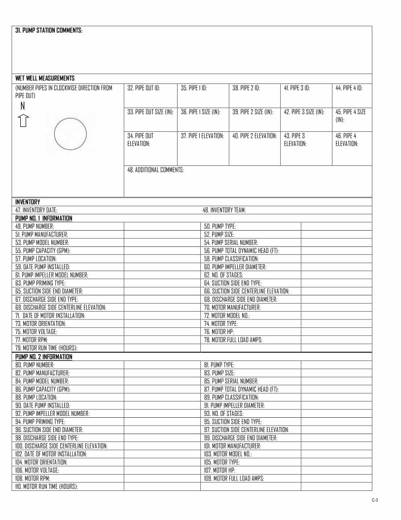
C-3
31. PUMP STATION COMMENTS:
WET WELL MEASUREMENTS
(NUMBER PIPES IN CLOCKWISE DIRECTION FROM
PIPE OUT)
N
32. PIPE OUT ID: 35. PIPE 1 ID: 38. PIPE 2 ID: 41. PIPE 3 ID: 44. PIPE 4 ID:
33. PIPE OUT SIZE (IN): 36. PIPE 1 SIZE (IN): 39. PIPE 2 SIZE (IN): 42. PIPE 3 SIZE (IN): 45. PIPE 4 SIZE
(IN):
34. PIPE OUT
ELEVATION:
37. PIPE 1 ELEVATION: 40. PIPE 2 ELEVATION: 43. PIPE 3
ELEVATION:
46. PIPE 4
ELEVATION:
48. ADDITIONAL COMMENTS:
INVENTORY
47. INVENTORY DATE: 48. INVENTORY TEAM:
PUMP NO. 1 INFORMATION
49. PUMP NUMBER: 50. PUMP TYPE:
51. PUMP MANUFACTURER; 52. PUMP SIZE:
53. PUMP MODEL NUMBER: 54. PUMP SERIAL NUMBER:
55. PUMP CAPACITY (GPM): 56. PUMP TOTAL DYNAMIC HEAD (FT):
57. PUMP LOCATION: 58. PUMP CLASSIFICATION:
59. DATE PUMP INSTALLED: 60. PUMP IMPELLER DIAMETER:
61. PUMP IMPELLER MODEL NUMBER: 62. NO. OF STAGES:
63. PUMP PRIMING TYPE: 64. SUCTION SIDE END TYPE:
65. SUCTION SIDE END DIAMETER: 66. SUCTION SIDE CENTERLINE ELEVATION:
67. DISCHARGE SIDE END TYPE: 68. DISCHARGE SIDE END DIAMETER:
69. DISCHARGE SIDE CENTERLINE ELEVATION: 70. MOTOR MANUFACTURER:
71. DATE OF MOTOR INSTALLATION: 72. MOTOR MODEL NO.:
73. MOTOR ORIENTATION: 74. MOTOR TYPE:
75. MOTOR VOLTAGE: 76. MOTOR HP:
77. MOTOR RPM: 78. MOTOR FULL LOAD AMPS:
79. MOTOR RUN TIME (HOURS):
PUMP NO. 2 INFORMATION
80. PUMP NUMBER: 81. PUMP TYPE:
82. PUMP MANUFACTURER; 83. PUMP SIZE:
84. PUMP MODEL NUMBER: 85. PUMP SERIAL NUMBER:
86. PUMP CAPACITY (GPM): 87. PUMP TOTAL DYNAMIC HEAD (FT):
88. PUMP LOCATION: 89. PUMP CLASSIFICATION:
90. DATE PUMP INSTALLED: 91. PUMP IMPELLER DIAMETER:
92. PUMP IMPELLER MODEL NUMBER: 93. NO. OF STAGES:
94. PUMP PRIMING TYPE: 95. SUCTION SIDE END TYPE:
96. SUCTION SIDE END DIAMETER: 97. SUCTION SIDE CENTERLINE ELEVATION:
98. DISCHARGE SIDE END TYPE: 99. DISCHARGE SIDE END DIAMETER:
100. DISCHARGE SIDE CENTERLINE ELEVATION: 101. MOTOR MANUFACTURER:
102. DATE OF MOTOR INSTALLATION: 103. MOTOR MODEL NO.:
104. MOTOR ORIENTATION: 105. MOTOR TYPE:
106. MOTOR VOLTAGE: 107. MOTOR HP:
108. MOTOR RPM: 109. MOTOR FULL LOAD AMPS:
110. MOTOR RUN TIME (HOURS):
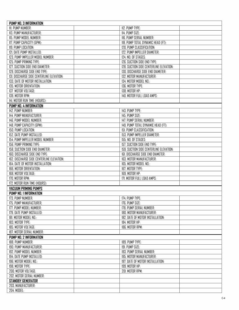
C-4
PUMP NO. 3 INFORMATION
111. PUMP NUMBER: 112. PUMP TYPE:
113. PUMP MANUFACTURER; 114. PUMP SIZE:
115. PUMP MODEL NUMBER: 116. PUMP SERIAL NUMBER:
117. PUMP CAPACITY (GPM): 118. PUMP TOTAL DYNAMIC HEAD (FT):
119. PUMP LOCATION: 120. PUMP CLASSIFICATION:
121. DATE PUMP INSTALLED: 122. PUMP IMPELLER DIAMETER:
123. PUMP IMPELLER MODEL NUMBER: 124. NO. OF STAGES:
125. PUMP PRIMING TYPE: 126. SUCTION SIDE END TYPE:
127. SUCTION SIDE END DIAMETER: 128. SUCTION SIDE CENTERLINE ELEVATION:
129. DISCHARGE SIDE END TYPE: 130. DISCHARGE SIDE END DIAMETER:
131. DISCHARGE SIDE CENTERLINE ELEVATION: 132. MOTOR MANUFACTURER:
133. DATE OF MOTOR INSTALLATION: 134. MOTOR MODEL NO.:
135. MOTOR ORIENTATION: 136. MOTOR TYPE:
137 MOTOR VOLTAGE: 138. MOTOR HP:
139. MOTOR RPM: 140. MOTOR FULL LOAD AMPS:
141. MOTOR RUN TIME (HOURS):
PUMP NO. 4 INFORMATION
142. PUMP NUMBER: 143. PUMP TYPE:
144. PUMP MANUFACTURER; 145. PUMP SIZE:
146. PUMP MODEL NUMBER: 147. PUMP SERIAL NUMBER:
148. PUMP CAPACITY (GPM): 149. PUMP TOTAL DYNAMIC HEAD (FT):
150. PUMP LOCATION: 151. PUMP CLASSIFICATION:
152. DATE PUMP INSTALLED: 153. PUMP IMPELLER DIAMETER:
154. PUMP IMPELLER MODEL NUMBER: 155. NO. OF STAGES:
156. PUMP PRIMING TYPE: 157. SUCTION SIDE END TYPE:
158. SUCTION SIDE END DIAMETER: 159. SUCTION SIDE CENTERLINE ELEVATION:
160. DISCHARGE SIDE END TYPE: 161. DISCHARGE SIDE END DIAMETER:
162. DISCHARGE SIDE CENTERLINE ELEVATION: 163. MOTOR MANUFACTURER:
164. DATE OF MOTOR INSTALLATION: 165. MOTOR MODEL NO.:
166. MOTOR ORIENTATION: 167. MOTOR TYPE:
168. MOTOR VOLTAGE: 169. MOTOR HP:
170. MOTOR RPM: 171. MOTOR FULL LOAD AMPS:
172. MOTOR RUN TIME (HOURS):
VACUUM PRIMING PUMPS
PUMP NO. 1 INFORMATION
173. PUMP NUMBER: 174. PUMP TYPE:
175. PUMP MANUFACTURER; 176. PUMP SIZE:
177. PUMP MODEL NUMBER: 178. PUMP SERIAL NUMBER:
179. DATE PUMP INSTALLED: 180. MOTOR MANUFACTURER:
181. MOTOR MODEL NO.: 182. DATE OF MOTOR INSTALLATION:
183. MOTOR TYPE: 184. MOTOR HP:
185. MOTOR VOLTAGE: 186. MOTOR RPM:
187. MOTOR SERIAL NUMBER:
PUMP NO. 2 INFORMATION
188. PUMP NUMBER: 189. PUMP TYPE:
190. PUMP MANUFACTURER; 191. PUMP SIZE:
192. PUMP MODEL NUMBER: 193. PUMP SERIAL NUMBER:
194. DATE PUMP INSTALLED: 195. MOTOR MANUFACTURER:
196. MOTOR MODEL NO.: 197. DATE OF MOTOR INSTALLATION:
198. MOTOR TYPE: 199. MOTOR HP:
200. MOTOR VOLTAGE: 201. MOTOR RPM:
202. MOTOR SERIAL NUMBER:
STANDBY GENERATOR
203. MANUFACTURER:
204. MODEL:

C-5
205. YEAR OF MANUFACTURE:
206. SERIAL NUMBER:
207. ENGINE (KW):
208. ENGINE CYLINDERS:
209. ENGINE RPM:
210. ENGINE FUEL:
211. ENGINE PISTON AREA:
212. ENGINE RUN TIME (H):
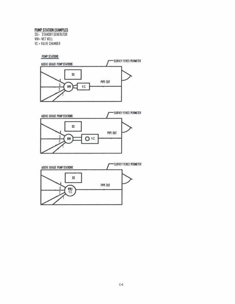
C-6
PUMP STATION EXAMPLES
SG= STANDBY GENERATOR
WW= WET WELL
VC = VALVE CHAMBER