Embed Size (px)
Citation preview

Drive Technology \ Drive Automation \ System Integration \ Services
Catalog
KES.37 and RESF37 Series Stainless Steel Gear Units
Edition 04/2010 16870727 / US
SEW-EURODRIVE—Driving the world

Contents
Contents1 Product description......................................................................................................... 5
1.1 Housing design....................................................................................................... 51.2 Motor mounting ...................................................................................................... 51.3 Surface protection .................................................................................................. 51.4 Ambient temperature.............................................................................................. 5
2 Mounting positions.......................................................................................................... 6
2.1 Key to the mounting position sheets ...................................................................... 62.2 KES.37 helical-bevel gear units ............................................................................. 72.3 RESF37 helical gear units...................................................................................... 9
3 Operating notes ............................................................................................................. 10
3.1 Lubricants............................................................................................................. 103.2 Lubricant fill quantities.......................................................................................... 12
4 Gear unit dimensions .................................................................................................... 13
5 Selection tables for AESM adapters (IEC and NEMA variant) ................................... 14
5.1 KES.37 with AESM adapter ................................................................................. 145.2 RESF37 with AESM adapter ................................................................................ 15
6 Dimension sheets – [in] ................................................................................................ 16
6.1 KES.37 ................................................................................................................. 166.2 RESF37................................................................................................................ 22
7 Available output shafts ................................................................................................. 24
7.1 K Series inch solid shafts ..................................................................................... 247.2 K Series metric solid shafts .................................................................................. 257.3 K Series inch hollow shafts .................................................................................. 267.4 K Series metric hollow shafts ............................................................................... 277.5 K Series TorqLOC................................................................................................ 287.6 R Series inch solid shafts ..................................................................................... 297.7 R Series metric solid shafts.................................................................................. 30
8 Appendix ........................................................................................................................ 31
8.1 Address list........................................................................................................... 318.2 Index..................................................................................................................... 39

Contents

Catalog – KES.37 and RESF37 Stainless Steel Gear Units 5
1Housing designProduct description 1Housing designProduct description
Stainless Steel Gear Units KES.37 und RESF371 Product description
1.1 Housing designThe efficiency-optimized KES.37.. helical-bevel gear units are characterized by an opti-mized housing design and the use of stainless steel. Recesses that can collect dirt andliquid have been eliminated. Thus the gear unit surface is easy to clean and is chemicalresistant.
1.2 Motor mountingThe IEC and NEMA adapters, also made of stainless steel, allow for a variable motormounting.
1.3 Surface protectionThe stainless steel variant is resistant to corrosion according to the operating conditionslisted in section "Cleaning recommendation" in the corresponding operating instructions.
1.4 Ambient temperatureGear units/gearmotors can be used at ambient temperatures between - 20 °C and+ 40 °C . Consult SEW-EURODRIVE if the ambient temperatures exceed this tempera-ture range.
INFORMATIONThe present addendum to the "Gear Units" catalog comprises the KES.37 and RESF37stainless steel gear units.
Please use the data specified in this publication. This document does not replace thecomprehensive "Gear Units" catalog.
Pi
fkVA
Hz
n
Pi
fkVA
Hz
n

2 Key to the mounting position sheetsMounting positions
2 Mounting positions
2.1 Key to the mounting position sheets
2.1.1 Symbols usedThe following table shows the symbols used in the mounting position sheets and theirmeaning:
Symbol Meaning
Breather valve
Oil level plug
Oil drain plug
INFORMATIONNotes on the shafts illustrated on the mounting position sheets.
Observe the following information regarding the illustrations on the mounting positionsheets:• For gear units with solid shaft: The displayed shaft is always on the A end.• For shaft-mounted gear units: The shaft with dashed lines represents the
customer shaft. The output end ( = shaft position) is always shown on the A end.
INFORMATIONNotes on the illustrated motors. Motors are only represented symbolically on the mounting position sheets.

Catalog – KES.37 and RESF37 Stainless Steel Gear Units 7
2KES.37 helical-bevel gear unitsMounting positions 2KES.37 helical-bevel gear unitsMounting positions
2.2 KES.37 helical-bevel gear units

2 KES.37 helical-bevel gear unitsMounting positions

Catalog – KES.37 and RESF37 Stainless Steel Gear Units 9
2RESF37 helical gear unitsMounting positions 2RESF37 helical gear unitsMounting positions
2.3 RESF37 helical gear units
2385788555
3 LubricantsOperating notes
3 Operating notes
3.1 Lubricants
3.1.1 General informationUnless a special arrangement is made, SEW-EURODRIVE supplies the drives with alubricant fill adapted for the specific gear unit and mounting position. The mounting po-sition, M1 – M6, must be specified with the order. See "Mounting positions", page 6. Youmust adapt the lubricant fill if you change the mounting position subsequently (� "Lu-bricant fill quantities", page 12).
3.1.2 Lubricant tableThe lubricant table on the following page shows the permitted lubricants for SEW-EU-RODRIVE gear units. Observe the following key to the lubricant table.
Key to the lubricant table
Abbreviations, meaning of shading and notes:CLP PG = Polyglycol (W gear units, conforms to USDA-H1)CLP HC = Synthetic hydrocarbonsCLP HC NSF H1 = Synthetic hydrocarbons (NSF H1 certification)E = Ester oil (water hazard classification 1)
= Synthetic lubricant (= synthetic-based roller bearing grease)= Mineral lubricant (= mineral-based rolling bearing grease)
4) Observe the critical starting behavior at low temperatures.
6) Ambient temperature
Lubricant for the food industry (food grade oil)
Biodegradable oil (lubricant for agriculture, forestry, and water management)OilOil
Pi
fkVA
Hz
n
Pi
fkVA
Hz
n

Catalog – KES.37 and RESF37 Stainless Steel Gear Units 11
3LubricantsOperating notes 3LubricantsOperating notes
2295553419
Oil
Oil
Oil
DIN
(ISO
)IS
O,N
LGI
Mo
bil®
0+1
00+5
0
6)
-50
°CTO
T A
LO
T A
L
33 196 00 09
Tr
ibol
O
ptim
ol
KES
RES
-25
+80
+60
VG 2
20M
obil
Gly
goyl
e 22
0Sh
ell T
ivel
aS
220
Klü
bers
ynth
GH
6-2
20A
ral D
egol
GS
220
BP
Ener
sSG
-XP
2yn 20
Syn
CLP
lube
220
Trib
ol80
0/22
0O
ptifl
ex A
220
Ren
olin
PG 2
20C
arte
r SY
220
-25
VG 2
20M
obil
SHC
630
Shel
l OH
Dm
ala
220
Klü
bers
ynth
GEM
4-2
20 N
Ara
l Deg
olPA
S 22
0Pi
n EPna
cle
220
Trib
ol15
10/2
20O
ptig
ear
Synt
hetic
X 2
20R
enol
in U
nisy
nC
LP 2
20
-40
+40
VG 1
50M
obil
SHC
629
Shel
l Om
ala
HD
150
Klü
bers
ynth
GEM
4-1
50 N
Pin EPna
cle
150
Opt
igea
rSy
nthe
tic X
150
Ren
olin
Uni
syn
CLP
150
Car
ter S
H 1
50
-40
+20
VG 6
8M
obil
SHC
626
Mob
ilSH
C 6
24
Ren
olin
Uni
syn
CLP
68
-40
+10
CLP
HC
VG 3
2K
lübe
r-Su
mm
itH
ySyn
FG
-32
Cet
usPA
O 4
6O
ptile
b H
Y 32
Ren
olin
Uni
syn
OL3
2D
acni
s SH
32
-10
+40
VG 4
60Sh
ell C
assi
daFl
uid
GL
460
Klü
berö
l4U
H1-
460
NO
ptile
bG
T 46
0G
eral
ynSF
460
-25
+25
VG 2
20
CLP
HC
NSF
H1
Shel
l Cas
sida
Flui
d G
L 22
0K
lübe
röl
4UH
1-22
0 N
Opt
ileb
GT
220
-40
0VG
68
Shel
l Cas
sida
Flui
d H
F 68
Klü
berö
l4U
H1-
68 N
Opt
ileb
HY
68
-20
+40
VG 4
60E
Klü
berb
ioC
A2-
460
Trib
ol B
io T
op
1418
/460
Plan
toge
ar46
0 S
CLP
PG
Oil
Oil
4) 4) 4) 4)
Stan
dard
Pi
fkVA
Hz
n
Pi
fkVA
Hz
n

3 Lubricant fill quantitiesOperating notes
3.2 Lubricant fill quantitiesThe specified fill quantities are guide values. The precise values vary depending on thegear ratio. Check the oil level plug for the exact oil quantity.
The following table shows guide values for lubricant fill quantities in relation to themounting position M1 – M6.
KES.37
RESF37
Fill quantity in liters
Gear unit M1 M2 M3 M4 M5 M6
KES.37 0.50 1.10 1.10 1.40 1.10 1.10
Fill quantity in litersGear unit M1 M2 M3 M4 M5 M6RESF37 0.40 1.00 1.00 1.25 1.00 1.00
Pi
fkVA
Hz
n
Pi
fkVA
Hz
n

Catalog – KES.37 and RESF37 Stainless Steel Gear Units 13
4Lubricant fill quantitiesGear unit dimensions 4Lubricant fill quantitiesGear unit dimensions
4 Gear unit dimensionsThe dimensions of the gear units are described below:
2190650891
B5 Centering diameter L1 Maximum insertion depth of motor shaft
C5 Flange thickness L5 Distance between shaft shoulder and flange
D1 Coupling bore diameter S5 Tapped hole/clearance hole
E5 Hole circle diameter T1 Bore with groove
F5 Centering depth U1 Groove width
G5 Flange diameter Z5 Adapter length
L Total length of the gear unit with adapter
Pi
fkVA
Hz
n
Pi
fkVA
Hz
n
5 KES.37 with AESM adapterSelection tables for AESM adapters (IEC and NEMA variant)
5 Selection tables for AESM adapters (IEC and NEMA variant)
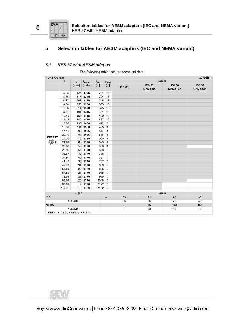
5.1 KES.37 with AESM adapterThe following table lists the technical data:
ne = 1700 rpm 1770 lb-ini na Ta max FRa � (/R) AESM
[rpm] [lb-in] [lb] [ ' ] IEC 63 IEC 71NEMA 56
IEC 80NEMA143
IEC 90NEMA145
KESA37
3.98 427 1105 294 13 5.36 317 1240 324 13 6.37 267 1285 346 13 6.80 250 1330 353 13 7.96 214 1370 375 13 8.91 191 1415 391 12 10.49 162 1415 429 12 12.14 140 1415 463 12 13.08 130 1460 472 9 15.31 111 1550 495 8 17.15 99 1595 517 8 20.19 84 1635 555 8 23.36 73 1725 580 8 24.99 68 1770 593 8 28.83 59 1770 638 8 29.96 57 1770 650 7 35.57 48 1770 708 7 37.97 45 1770 731 7 44.46 38 1770 787 7 49.79 34 1770 830 7 58.60 29 1770 895 7 67.80 25 1770 955 7 72.54 23 1770 985 7 83.69 20 1770 1048 7 97.81 17 1770 1122 7 106.38 16 1770 1162 7
m [lb] AESMIEC s 63 71 80 90
KESA37 36 36 45 45NEMA - 56 143 145
KESA37 - 38 42 42 KESF: + 7.3 lb/ KESAF: + 5.5 lb
3
Pi
fkVA
Hz
n

Catalog – KES.37 and RESF37 Stainless Steel Gear Units 15
5RESF37 with AESM adapterSelection tables for AESM adapters (IEC and NEMA variant) 5RESF37 with AESM adapterSelection tables for AESM adapters (IEC and NEMA variant)
5.2 RESF37 with AESM adapterThe following table lists the technical data:
ne = 1700 rpm 1770 lb-ini na Ta max FRa � (/R) AESM
[rpm] [lb-in] [lb] [ ' ] IEC 63 IEC 71NEMA 56
IEC 80NEMA143
IEC 90NEMA145
RESF37
3.41 499 990 123 14 4.05 420 1080 107 13 4.32 393 1115 101 13 5.06 336 1195 91 13 5.67 300 1255 83 12 6.67 255 1275 127 12 7.97 213 1380 265 8 9.47 180 1480 270 8 10.11 168 1505 279 8 11.83 144 1620 272 8 13.25 128 1680 283 8 15.60 109 1770 303 8 18.05 94 1770 375 8 19.31 88 1770 409 7 22.27 76 1770 483 7 26.03 65 1635 654 7 28.32 60 1770 618 7
RESF37
24.42 70 1770 533 9 28.73 59 1770 627 9 32.40 52 1770 699 9 36.72 46 1770 776 9 39.17 43 1770 818 9 44.81 38 1770 906 9 48.08 35 1770 955 9 55.76 30 1770 1061 9 61.18 28 1770 1129 8 69.33 25 1770 1187 8 73.96 23 1770 1216 8 84.61 20 1770 1281 8 90.77 19 200 1317 8 105.28 16 200 1394 8 123.66 14 200 1481 8 134.82 13 200 1502 8
m [lb] AESMIEC s 63 71 80 90
RESF37 31 31 38 38RESF37 31 34 38 38
NEMA - 56 143 145RESF37 - 34 38 38RESF37 - 34 38 38
2
3
Pi
fkVA
Hz
n
6 KES.37Dimension sheets – [in]
6 Dimension sheets – [in]6.1 KES.37
B5 C5 E5 F5 G5 L S5 Z5 D1 L1 T1 U1AESM63 (IEC) 3.74 0.32 4.53 0.16 6.30 11.44 M8 2.85 0.43 0.91 0.50 0.16AESM71 (IEC) 4.33 0.32 5.11 0.16 6.30 11.44 M8 2.85 0.55 1.18 0.64 0.20AESM80 (IEC) 5.12 0.39 6.50 0.16 7.87 12.76 M10 4.17 0.75 1.57 0.86 0.24AESM90 (IEC) 5.12 0.39 6.50 0.16 7.87 12.76 M10 4.17 0.94 1.97 1.07 0.32
7.22
0.33
4.72
3.70
R 0
.86
8.94
5.47
0.39
1.22 0.
51 0.18
0.59
2.26 0.24
5.12
.63
2.48 2.36
0.10
0.25 2.362.36
1.37
7/16-14x1.000.68
4.13
1.25
0 1.77H
7
1.42 0.98
1.77
mm
mmmm
mm
1.22 0.79
2.363.39
3.19
3.5 2.36
0.10
IS0 4017M10X15-8.8
F5
B5
G5
U1
T1 S5
D1
L1
C510
0mm
-0.5
L
Z5
E5
Pi
fkVA
Hz
n

Catalog – KES.37 and RESF37 Stainless Steel Gear Units 17
6KES.37Dimension sheets – [in] 6KES.37Dimension sheets – [in]
B5 C5 E5 F5 G5 L S5 Z5 D1 L1 T1 U1AESM63 (IEC) 3.74 0.32 4.53 0.16 6.30 11.44 M8 2.85 0.43 0.91 0.50 0.16AESM71 (IEC) 4.33 0.32 5.11 0.16 6.30 11.44 M8 2.85 0.55 1.18 0.64 0.20AESM80 (IEC) 5.12 0.39 6.50 0.16 7.87 12.76 M10 4.17 0.75 1.57 0.86 0.24AESM90 (IEC) 5.12 0.39 6.50 0.16 7.87 12.76 M10 4.17 0.94 1.97 1.07 0.32
0.35
8.94
5.474.
72
5.12
0.33 7.
22
3.94
2.26 5.59
0.39
0.14
1.97
6.30
110m
m
1.00
0-0
.000
51.
000
-0.0
005
1.11
1.31
1.97
0.330.25
D 3/8-16x0.86
2.48 2.36 1.36
6.30
0.25 2.36 2.36
1.37
0.68
1.77
4.13
1.25
0H
7
7/16-14x1.00
3.1
9
3.98 2.36 1.356
.30
3.39 2.36
1.22 0.79
1.7
7
1.42 0.98
30
mm
h6
30
mm
h6
30
mm
H7
30
mm
H7
Z5
L
E5
F5
B5
G5
U1
T1
D1
S5
L1
C5
Pi
fkVA
Hz
n

6 KES.37Dimension sheets – [in]
B5 C5 E5 F5 G5 L S5 Z5 D1 L1 T1 U1AESM63 (IEC) 3.74 0.32 4.53 0.16 6.30 11.44 M8 2.85 0.43 0.91 0.50 0.16AESM71 (IEC) 4.33 0.32 5.11 0.16 6.30 11.44 M8 2.85 0.55 1.18 0.64 0.20AESM80 (IEC) 5.12 0.39 6.50 0.16 7.87 12.76 M10 4.17 0.75 1.57 0.86 0.24AESM90 (IEC) 5.12 0.39 6.50 0.16 7.87 12.76 M10 4.17 0.94 1.97 1.07 0.32
SymmetricalNON-Symmetrical
7.22 3.70
100m
m-0
.5
8.94
5.47
4.72
0.33
L
F5
G5
B5
U1
T1
E5
Z5
C5
S5
D1
L1
R 0.
86
2.26 0.24
5.12
ISO 4017M10X15-8.8
1.22
0.39
0.180.51
0.59
0.63M10
3.98
3.19
3.03
0.753.
193.98
6.69 -0.20
3.70 2.80
1.30
3.70
1.30
1.25
0H
7
1.25
0H
7
1.25
0h
11
Rz 16
1.25
0H
7
1.25
0H
7
Rz 16
max
. 0.0
05
1.25
0h
11
max
. 0.0
05
3.74
3.97
1.69
7.65-0.20
Pi
fkVA
Hz
n

Catalog – KES.37 and RESF37 Stainless Steel Gear Units 19
6KES.37Dimension sheets – [in] 6KES.37Dimension sheets – [in]
B5 C5 E5 F5 G5 L S5 Z5 D1 L1 T1 U1 L5 L2 Z12AESM56 (NEMA) 4.50 0.43 5.87 0.18 6.69 12.13 0.41 3.61 0.625 1.88 0.71 0.185 -0.19 2.08 0.85AESM143 (NEMA) 4.50 0.47 5.87 0.18 6.69 13.12 0.41 4.54 0.875 2.25 0.97 0.1875 0.11 2.14 0.46AESM145 (NEMA) 4.50 0.47 5.87 0.18 6.69 13.12 0.41 4.54 0.875 2.25 0.97 0.1875 0.11 2.14 0.46
L
B5
G5
F5
Z5
7.22 3.70
8.94
5.47
4.72
0.33
100m
m-0
.5E5
U1
T1
D1
S5
C5
L1 L5
ISO 4017M10x15-8.8
0.39
R 0
.86
2.26 0.24
5.12
1.22
0.51
0.18
0.59
M10
0.63
2.48 2.36
0.10
1.37
0.25 2.36 2.36
0.68
4.13
1.25
0H
7
1.77
3.19
3.50 2.36
0.10
3.39 2.36
1.22 0.79
1.77
1.42 0.98
30m
m30
mm
H7
30m
mH
7
h6
30m
mh
6
7/16-14x1.00
Pi
fkVA
Hz
n
6 KES.37Dimension sheets – [in]
B5 C5 E5 F5 G5 L S5 Z5 D1 L1 T1 U1 L5 L2 Z12AESM56 (IEC) 4.50 0.43 5.87 0.18 6.69 12.13 0.41 3.61 0.625 1.88 0.71 0.1875 -0.19 2.08 0.85AESM143 (IEC) 4.50 0.47 5.87 0.18 6.69 13.12 0.41 4.54 0.875 2.25 0.97 0.1875 0.11 2.14 0.46AESM145 (IEC) 4.50 0.47 5.87 0.18 6.69 13.12 0.41 4.54 0.875 2.25 0.97 0.1875 0.11 2.14 0.46
E5
L
Z5
B5
G5
F5
U1
T1
0.35
8.94
5.47
4.72
5.120.
33
S5
C5
D1
L1 L5
7.22
3.94
2.26 5.59
0.39
0.14
1.97
6.30
110m
mj6
1.00
0 -0.
0005
1.00
0 -0.
0005
1.11
0.25 1.31
1.97
0.33
D 3/8-16x0.86
2.48 2.36 1.36
6.30
1.37
0.25 2.36 2.36
1.77
0.68
4.13
1.25
0H
7
7/16-14x1.00
3.19
3.98 2.36 1.35
6.30
3.39 2.36
1.22 0.79
30m
m
30m
m
H7
30m
mH
7
h6
30m
mh
6
1.77
1.42 0.98
Pi
fkVA
Hz
n

Catalog – KES.37 and RESF37 Stainless Steel Gear Units 21
6KES.37Dimension sheets – [in] 6KES.37Dimension sheets – [in]
B5 C5 E5 F5 G5 L S5 Z5 D1 L1 T1 U1 L5 L2 Z12AESM56 (NEMA) 4.50 0.43 5.87 0.18 6.69 12.13 0.41 3.61 0.625 1.88 0.71 0.1875 -0.19 2.08 0.85AESM143 (NEMA) 4.50 0.47 5.87 0.18 6.69 13.12 0.41 4.54 0.875 2.25 0.97 0.1875 0.11 2.14 0.46AESM145 (NEMA) 4.50 0.47 5.87 0.18 6.69 13.12 0.41 4.54 0.875 2.25 0.97 0.1875 0.11 2.14 0.46
SymmetricalNON-Symmetrical 3.98
3.19
3.70
1.30
1.25
0h
11
1.25
0H
7
1.25
0H
7
Rz 16
max
. 0.0
05
3.74
3.97
1.69
7.65-0.20
E5
L
Z5
F5B
5
G5
7.22
3.70
8.94
4.72
0.33
5.47
100m
m-0
.5
U1
T1
D1
S5
C5
L1 L5
R 0
.86
0.39
2.26 0.24
5.12
ISO 4017M10X15-8.8
1.22 0.51
0.59
0.18
M10 0.63
3.19
3.98 3.03
0.75
1.25
0
1.25
0
H7
1.25
0H
7
h11
max
. 0.0
05
1.30
6.69 -0.20
2.80
Rz 16
3.70
Pi
fkVA
Hz
n

6 RESF37Dimension sheets – [in]
6.2 RESF37
B5 C5 E5 F5 G5 L S5 Z5 D1 L1 T1 U1AESM63 (IEC) 3.74 0.32 4.53 0.16 6.30 11.00 M8 2.85 0.43 0.91 0.50 0.16AESM71 (IEC) 4.33 0.32 5.12 0.16 6.30 11.00 M8 2.85 0.55 1.18 0.64 0.197AESM80 (IEC) 5.12 0.39 6.47 0.16 7.87 12.32 M10 4.17 0.75 1.57 0.86 0.24AESM90 (IEC) 5.12 0.39 6.47 0.16 7.87 12.32 M10 4.17 0.95 1.97 1.08 0.32
E5
L
Z58.15
3.15
4.72
0.40
F5
B5
G5
1.00
0-0
.000
51.
000
-0.0
005
U1
C5
T1 S5
D1
L1
3.70
6.34
6.30
100m
mj6
0.14
1.97 0.39
0.35
5.12
0.33
1.97
1.31 0.25
1.11
D 3/8-16x0.86
Pi
fkVA
Hz
n

Catalog – KES.37 and RESF37 Stainless Steel Gear Units 23
6RESF37Dimension sheets – [in] 6RESF37Dimension sheets – [in]
B5 C5 E5 F5 G5 L L5 S5 Z5 D1 L1 T1 U1AESM56 (NEMA) 4.50 0.43 5.87 0.18 6.69 11.76 -0.20 0.41 3.61 0.625 1.875 0.71 0.1875AESM143 (NEMA) 4.50 0.47 5.87 0.18 6.69 12.69 0.11 0.41 4.54 0.875 2.25 0.97 0.1875AESM145 (NEMA) 4.50 0.47 5.87 0.18 6.69 12.69 0.11 0.41 4.54 0.875 2.25 0.97 0.1875
E5
L
Z5
F5B
5
G5
8.15
3.15
4.72
0.401.00
0 -0.0
005
1.00
0 -0.0
005
U1
D1
S5
C5
L1 L5
T1
3.70
6.34
0.33
1.97
1.31
1.11
0.25
D 3/8-16x0.86
6.30
0.14
1.97 0.39
0.35
5.12
110m
mj6
Pi
fkVA
Hz
n

7 K Series inch solid shaftsAvailable output shafts
7 Available output shafts7.1 K Series inch solid shafts
Model1)
1) Longer shafts to match older designs are available for flanged units.
D T U L L11 L12 M Change2)
2) Compared to standard shaft as shown in dimension pages.
KESF37 1 1.11 1/4 1.97 0.32 1-5/16 3/8 - 16 x 0.87 0
D
L
L11 L12
T
U
M
Pi
fkVA
Hz
n

Catalog – KES.37 and RESF37 Stainless Steel Gear Units 25
7K Series metric solid shaftsAvailable output shafts 7K Series metric solid shaftsAvailable output shafts
7.2 K Series metric solid shafts
Model1)
1) Longer shafts to match older designs are available for flanged units.
D T U L L11 L12 M Change2)
2) Compared to standard shaft as shown in dimension pages.
KESF37 25 28 8 50 5 40 M10 x 22 0
D
L
L11 L12
T
U
M
Pi
fkVA
Hz
n

7 K Series inch hollow shaftsAvailable output shafts
7.3 K Series inch hollow shafts
Model O8 D D7 T U L8 L9 M
KESA374.72 1.0 1.77 1.12 1/4 4.13 0.67 7/16 - 14 x 1
4.72 1.25 1.77 1.37 1/4 4.13 0.67 7/16 - 14 x 1
D D7
8
8
9L
O U
T
M
L
Pi
fkVA
Hz
n

Catalog – KES.37 and RESF37 Stainless Steel Gear Units 27
7K Series metric hollow shaftsAvailable output shafts 7K Series metric hollow shaftsAvailable output shafts
7.4 K Series metric hollow shafts
Model O8 D D7 T U L8 L9 M
KESA37 120 30 45 33.3 8 105 17 M10 x 25
D D7
8
8
9L
O U
T
M
L
Pi
fkVA
Hz
n

7 K Series TorqLOCAvailable output shafts
7.5 K Series TorqLOC
Metric and inch bores are available as shown below.
D D
DD
H7H7
h11 h11
EH EH
ModelInch shafts Metric shafts NON-
Symmetrical Symmetrical
D Dimension D Dimension EH
KEST37 1.00 1.1875 1.25 - - - 30 - 6.69 7.63
Pi
fkVA
Hz
n

Catalog – KES.37 and RESF37 Stainless Steel Gear Units 29
7R Series inch solid shaftsAvailable output shafts 7R Series inch solid shaftsAvailable output shafts
7.6 R Series inch solid shafts
Model1)
1) Longer shafts to match older designs are available for flanged units.
D T U L L11 L12 M Change2)
2) Compared to standard shaft as shown in dimension pages.
RESF37 1 1.11 1/4 1.97 0.26 1-5/16 3/8 - 16 x 0.87 0
D
L
L11 L12
T
U
M
Pi
fkVA
Hz
n

7 R Series metric solid shaftsAvailable output shafts
7.7 R Series metric solid shafts
Model1)
1) Longer shafts to match older designs are available for flanged units.
D T U L L11 L12 M Change2)
2) Compared to standard shaft as shown in dimension pages.
RESF37 25 28 8 50 3.5 50 M10 x 22 0
D
L
L11 L12
T
U
M
Pi
fkVA
Hz
n


![Chapter 220-340 WAC COMMERCIAL SHELLFISHlawfilesext.leg.wa.gov › law › WACArchive › 2018a › WAC 220... · (4/16/18) [Ch. 220-340 WAC p. 1] Chapter 220-340 Chapter 220-340](https://img.pdfslide.us/doc/110x75/5f162dc175b1e02bb6699872/chapter-220-340-wac-commercial-a-law-a-wacarchive-a-2018a-a-wac-220.jpg)