Embed Size (px)
Citation preview
1
Prof. Tzong-Lin Wu / NTUEE 1
Several Topics for Electronicsand Photonics
Prof. Tzong-Lin Wu
EMC Laboratory
Department of Electrical Engineering
National Taiwan University
Prof. Tzong-Lin Wu / NTUEE 2
Introduction
In the previous chapter, we introduced the principles of guided waves and learned that the mechanism of waveguiding is one in which the waves bounce obliquely between parallel planes as they progress along the structure. We studied transverse electric (TE) and transverse magnetic (TM) waves supported by plane conductors, as well as those supported by a plane dielectric slab.
Thus, we restricted our study of guided waves to one-dimensional structures.
In this chapter, we extend the treatment to two dimensions.
2
Prof. Tzong-Lin Wu / NTUEE 3
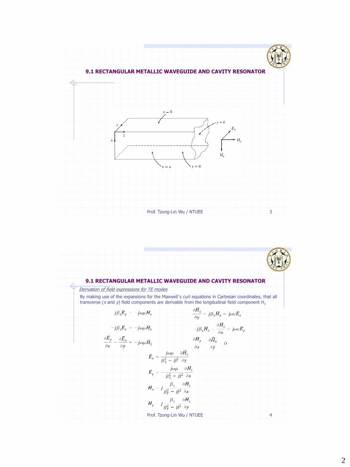
9.1 RECTANGULAR METALLIC WAVEGUIDE AND CAVITY RESONATOR
Prof. Tzong-Lin Wu / NTUEE 4
9.1 RECTANGULAR METALLIC WAVEGUIDE AND CAVITY RESONATOR
Derivation of field expressions for TE modes
By making use of the expansions for the Maxwell’s curl equations in Cartesian coordinates, that all
transverse (x and y) field components are derivable from the longitudinal field component Hz
3
Prof. Tzong-Lin Wu / NTUEE 5
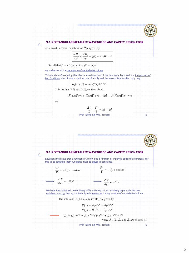
9.1 RECTANGULAR METALLIC WAVEGUIDE AND CAVITY RESONATOR
we make use of the separation of variables technique
This consists of assuming that the required function of the two variables x and y is the product of two functions, one of which is a function of x only and the second is a function of y only.
Prof. Tzong-Lin Wu / NTUEE 6
9.1 RECTANGULAR METALLIC WAVEGUIDE AND CAVITY RESONATOR
Equation (9.8) says that a function of x only plus a function of y only is equal to a constant. For this to be satisfied, both functions must be equal to constants.
We have thus obtained two ordinary differential equations involving separately the two variables x and y; hence, the technique is known as the separation of variables technique.
4
Prof. Tzong-Lin Wu / NTUEE 7
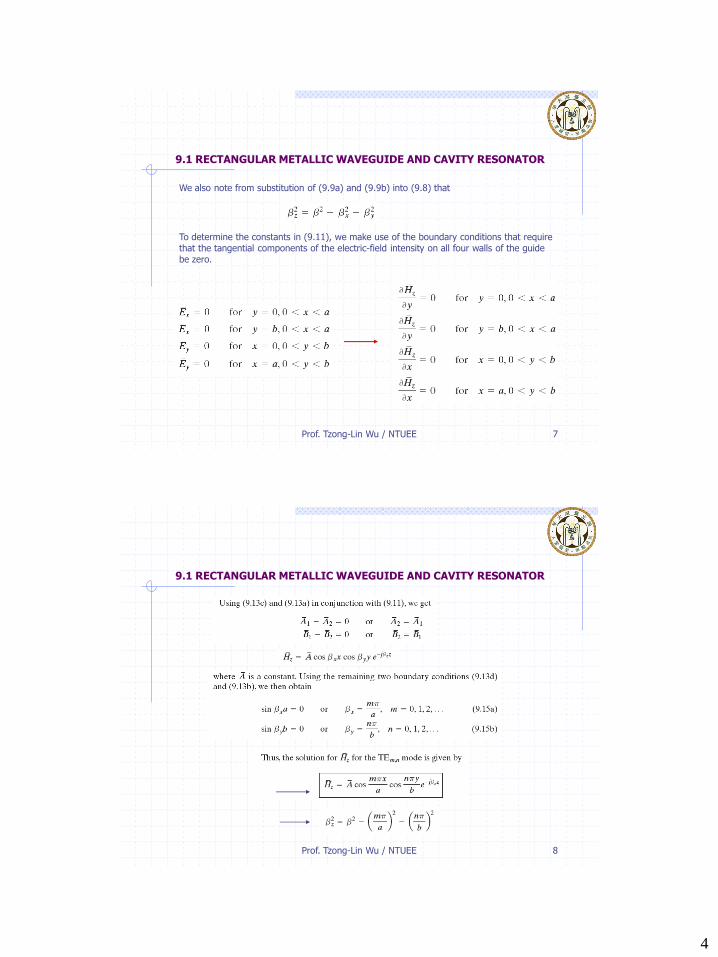
9.1 RECTANGULAR METALLIC WAVEGUIDE AND CAVITY RESONATOR
We also note from substitution of (9.9a) and (9.9b) into (9.8) that
To determine the constants in (9.11), we make use of the boundary conditions that require that the tangential components of the electric-field intensity on all four walls of the guide be zero.
Prof. Tzong-Lin Wu / NTUEE 8
9.1 RECTANGULAR METALLIC WAVEGUIDE AND CAVITY RESONATOR
5
Prof. Tzong-Lin Wu / NTUEE 9
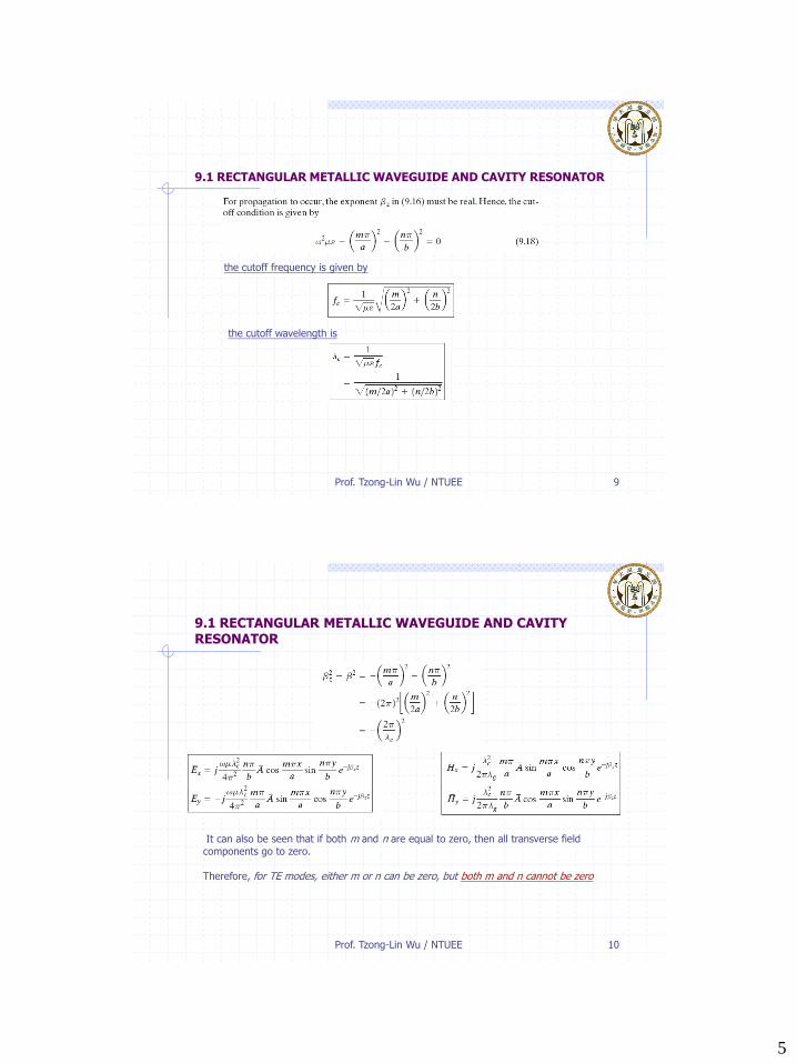
9.1 RECTANGULAR METALLIC WAVEGUIDE AND CAVITY RESONATOR
the cutoff frequency is given by
the cutoff wavelength is
Prof. Tzong-Lin Wu / NTUEE 10
9.1 RECTANGULAR METALLIC WAVEGUIDE AND CAVITY RESONATOR
It can also be seen that if both m and n are equal to zero, then all transverse field components go to zero.
Therefore, for TE modes, either m or n can be zero, but both m and n cannot be zero
6
Prof. Tzong-Lin Wu / NTUEE 11
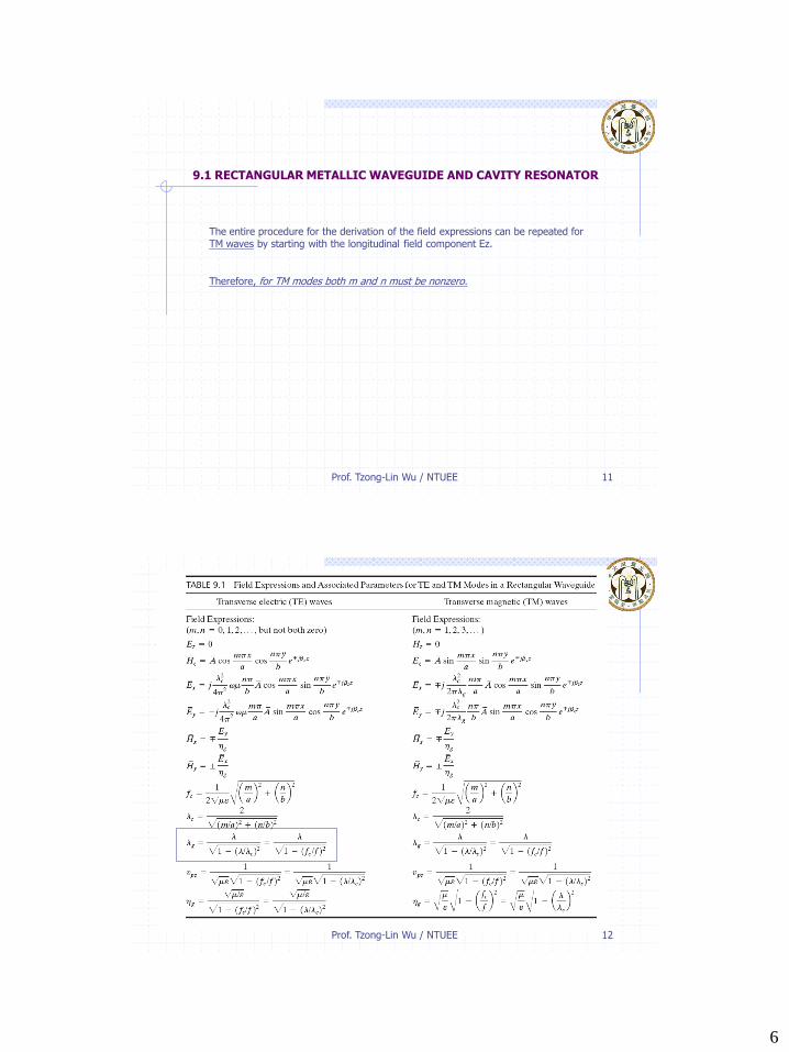
9.1 RECTANGULAR METALLIC WAVEGUIDE AND CAVITY RESONATOR
The entire procedure for the derivation of the field expressions can be repeated for TM waves by starting with the longitudinal field component Ez.
Therefore, for TM modes both m and n must be nonzero.
Prof. Tzong-Lin Wu / NTUEE 12
7
Prof. Tzong-Lin Wu / NTUEE 13
9.1 RECTANGULAR METALLIC WAVEGUIDE AND CAVITY RESONATOR
Dominant mode
Waveguides are, however, designed so that only one mode, the mode with thelowest cutoff frequency (or the largest cutoff wavelength), propagates. This isknown as the dominant mode.
From Table 9.1, we can see that the dominant mode is the TE1,0 mode or the TE0,1 mode, depending on whether the dimension a or the dimension b is the larger of the two.
By convention, the larger dimension is designated to be a, and hence the mode is the dominant mode.
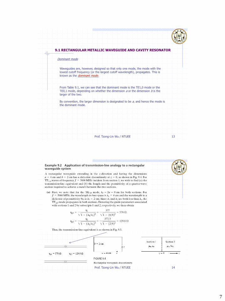
Prof. Tzong-Lin Wu / NTUEE 14
8
Prof. Tzong-Lin Wu / NTUEE 15
Prof. Tzong-Lin Wu / NTUEE 16
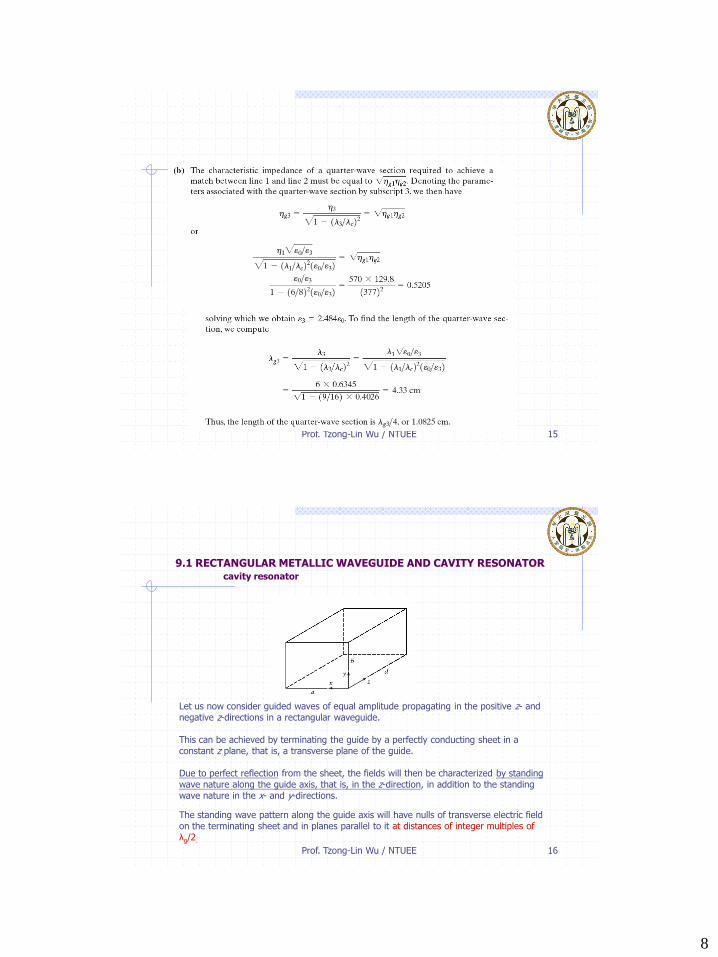
9.1 RECTANGULAR METALLIC WAVEGUIDE AND CAVITY RESONATORcavity resonator
The standing wave pattern along the guide axis will have nulls of transverse electric field on the terminating sheet and in planes parallel to it at distances of integer multiples of λg/2.
Let us now consider guided waves of equal amplitude propagating in the positive z- and negative z-directions in a rectangular waveguide.
This can be achieved by terminating the guide by a perfectly conducting sheet in a constant z plane, that is, a transverse plane of the guide.
Due to perfect reflection from the sheet, the fields will then be characterized by standing wave nature along the guide axis, that is, in the z-direction, in addition to the standing wave nature in the x- and y-directions.
9
Prof. Tzong-Lin Wu / NTUEE 17
9.1 RECTANGULAR METALLIC WAVEGUIDE AND CAVITY RESONATORcavity resonator
Such a structure is known as a cavity resonator and is the counterpart of the low-frequency lumped parameter resonant circuit at microwave frequencies, since it supports oscillations at frequencies for which the foregoing condition, that is,
Prof. Tzong-Lin Wu / NTUEE 18
9.1 RECTANGULAR METALLIC WAVEGUIDE AND CAVITY RESONATORcavity resonator
10
Prof. Tzong-Lin Wu / NTUEE 19
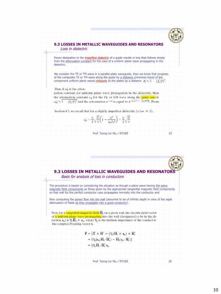
9.3 LOSSES IN METALLIC WAVEGUIDES AND RESONATORSLoss in dielectric
Power dissipation in the imperfect dielectric of a guide results in loss that follows simply from the attenuation constant for the case of a uniform plane wave propagating in the dielectric.
We consider the TE or TM wave in a parallel-plate waveguide, then we know that progress of the composite TE or TM wave along the guide by a distance d involves travel of the component uniform plane waves obliquely to the plates by a distance
Prof. Tzong-Lin Wu / NTUEE 20
9.3 LOSSES IN METALLIC WAVEGUIDES AND RESONATORSBasis for analysis of loss in conductors
The procedure is based on considering the situation as though a plane wave having the same magnetic field components as those given by the appropriate tangential magnetic field components on that wall for the perfect conductor case propagates normally into the conductor and
then computing the power flow into the wall (assumed to be of infinite depth in view of the rapid attenuation of fields as they propagate into a good conductor).
11
Prof. Tzong-Lin Wu / NTUEE 21
9.3 LOSSES IN METALLIC WAVEGUIDES AND RESONATORSBasis for analysis of loss in conductors
Prof. Tzong-Lin Wu / NTUEE 22
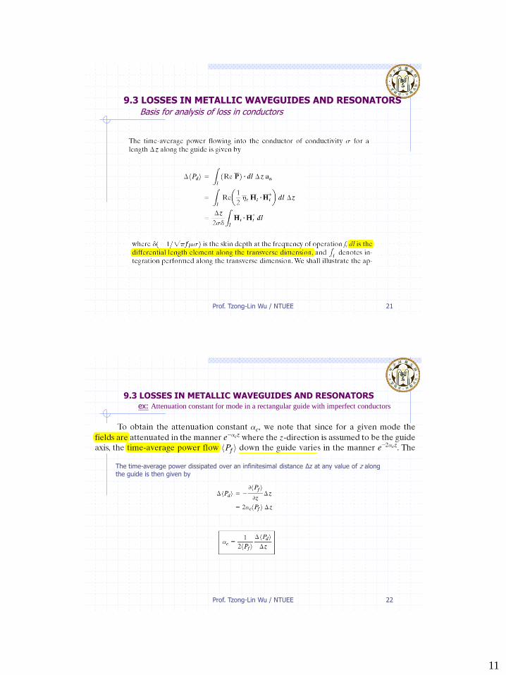
9.3 LOSSES IN METALLIC WAVEGUIDES AND RESONATORSex: Attenuation constant for mode in a rectangular guide with imperfect conductors
The time-average power dissipated over an infinitesimal distance Δz at any value of z alongthe guide is then given by
12
Prof. Tzong-Lin Wu / NTUEE 23
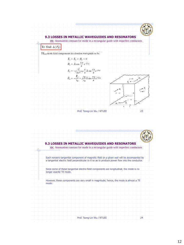
9.3 LOSSES IN METALLIC WAVEGUIDES AND RESONATORSex: Attenuation constant for mode in a rectangular guide with imperfect conductors
Prof. Tzong-Lin Wu / NTUEE 24
9.3 LOSSES IN METALLIC WAVEGUIDES AND RESONATORSex: Attenuation constant for mode in a rectangular guide with imperfect conductors
Each nonzero tangential component of magnetic field on a given wall will be accompanied by a tangential electric field perpendicular to it so as to produce power flow into the conductor.
Since some of these tangential electric-field components are longitudinal, the mode is no longer exactly TE mode.
However, these components are very small in magnitude; hence, the mode is almost a TE mode.
13
Prof. Tzong-Lin Wu / NTUEE 25
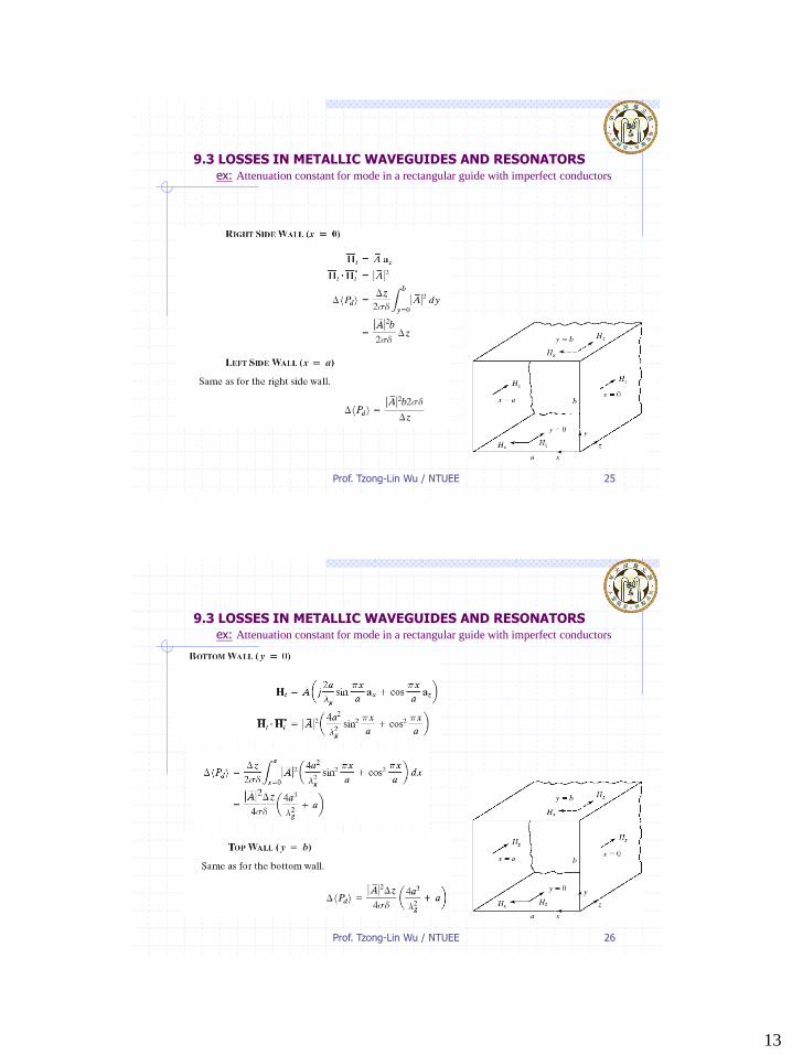
9.3 LOSSES IN METALLIC WAVEGUIDES AND RESONATORSex: Attenuation constant for mode in a rectangular guide with imperfect conductors
Prof. Tzong-Lin Wu / NTUEE 26
9.3 LOSSES IN METALLIC WAVEGUIDES AND RESONATORSex: Attenuation constant for mode in a rectangular guide with imperfect conductors
14
Prof. Tzong-Lin Wu / NTUEE 27
9.3 LOSSES IN METALLIC WAVEGUIDES AND RESONATORSex: Attenuation constant for mode in a rectangular guide with imperfect conductors
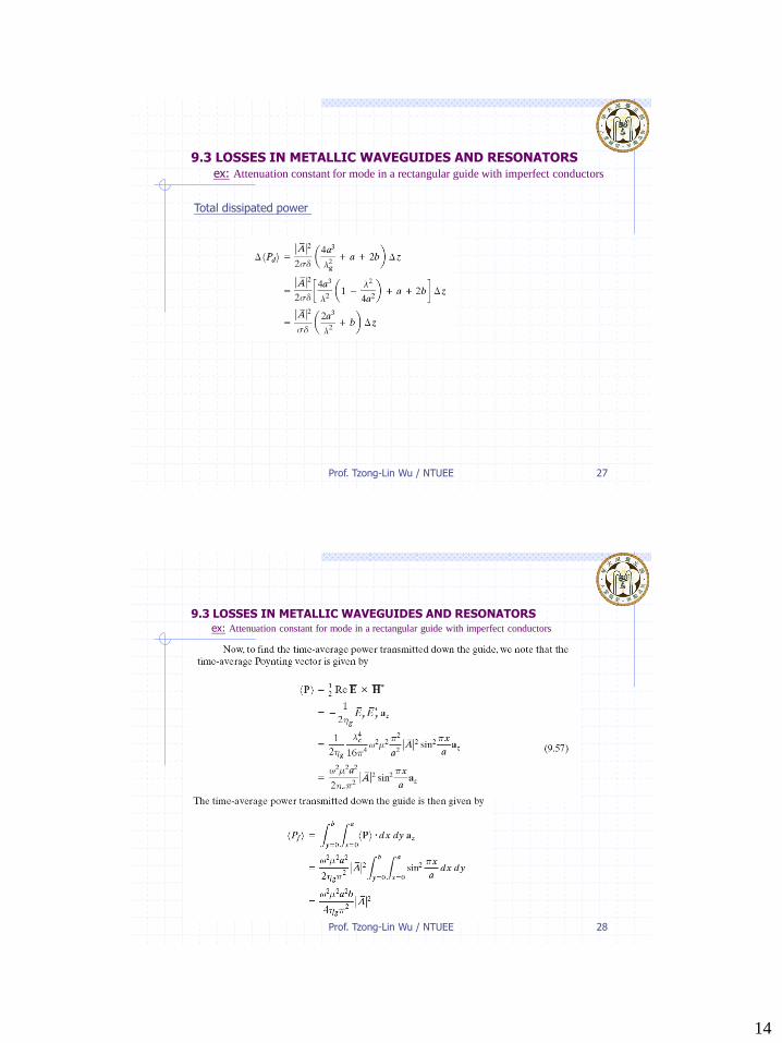
Total dissipated power
Prof. Tzong-Lin Wu / NTUEE 28
9.3 LOSSES IN METALLIC WAVEGUIDES AND RESONATORSex: Attenuation constant for mode in a rectangular guide with imperfect conductors
15
Prof. Tzong-Lin Wu / NTUEE 29
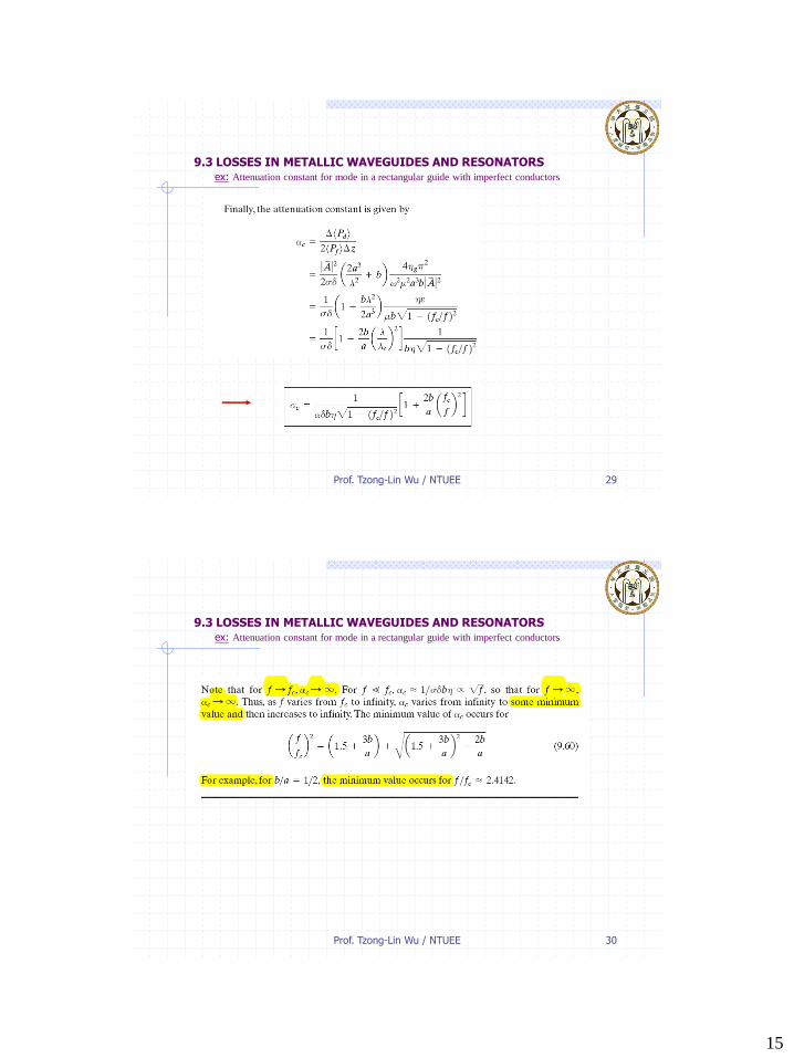
9.3 LOSSES IN METALLIC WAVEGUIDES AND RESONATORSex: Attenuation constant for mode in a rectangular guide with imperfect conductors
Prof. Tzong-Lin Wu / NTUEE 30
9.3 LOSSES IN METALLIC WAVEGUIDES AND RESONATORSex: Attenuation constant for mode in a rectangular guide with imperfect conductors
16
Prof. Tzong-Lin Wu / NTUEE 31
9.3 LOSSES IN METALLIC WAVEGUIDES AND RESONATORSQ factor of a resonator
The Q factor, which is a measure of the frequency selectivity of the resonator, is defined as
The power dissipated in them can be computed by analysis, as in Example 9.6 for the waveguide case.
As for the energy stored in the cavity, it is distributed between the electric and magneticfields at any arbitrary instant of time.
But there are particular values of time at which the electric field is maximum and the magnetic field is zero, and vice versa. At these values of time, the entire energy is stored in one of the two fields.
Prof. Tzong-Lin Wu / NTUEE 32
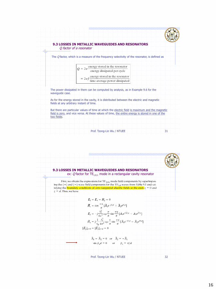
9.3 LOSSES IN METALLIC WAVEGUIDES AND RESONATORSex: Q factor for TE1,0,1 mode in a rectangular cavity resonator
17
Prof. Tzong-Lin Wu / NTUEE 33
9.3 LOSSES IN METALLIC WAVEGUIDES AND RESONATORSex: Q factor for TE1,0,1 mode in a rectangular cavity resonator
Prof. Tzong-Lin Wu / NTUEE 34
9.3 LOSSES IN METALLIC WAVEGUIDES AND RESONATORSex: Q factor for TE1,0,1 mode in a rectangular cavity resonator
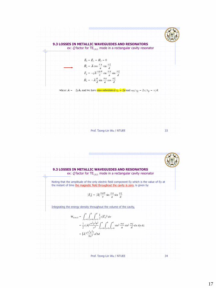
Noting that the amplitude of the only electric field component Ey which is the value of Ey atthe instant of time the magnetic field throughout the cavity is zero, is given by
Integrating the energy density throughout the volume of the cavity,
18
Prof. Tzong-Lin Wu / NTUEE 35
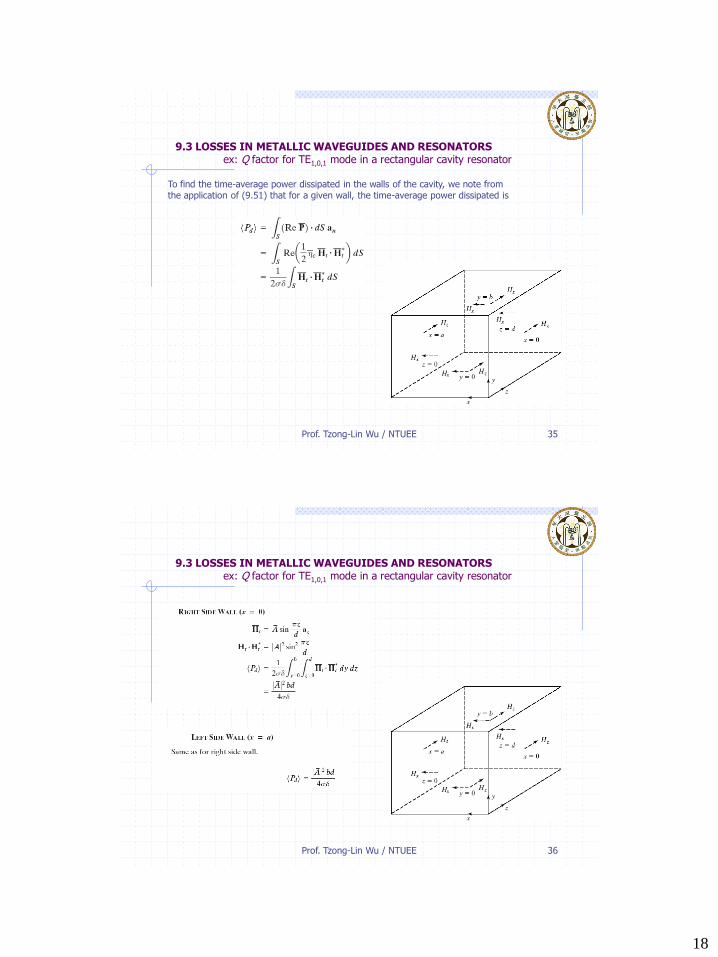
9.3 LOSSES IN METALLIC WAVEGUIDES AND RESONATORSex: Q factor for TE1,0,1 mode in a rectangular cavity resonator
To find the time-average power dissipated in the walls of the cavity, we note fromthe application of (9.51) that for a given wall, the time-average power dissipated is
Prof. Tzong-Lin Wu / NTUEE 36
9.3 LOSSES IN METALLIC WAVEGUIDES AND RESONATORSex: Q factor for TE1,0,1 mode in a rectangular cavity resonator
19
Prof. Tzong-Lin Wu / NTUEE 37
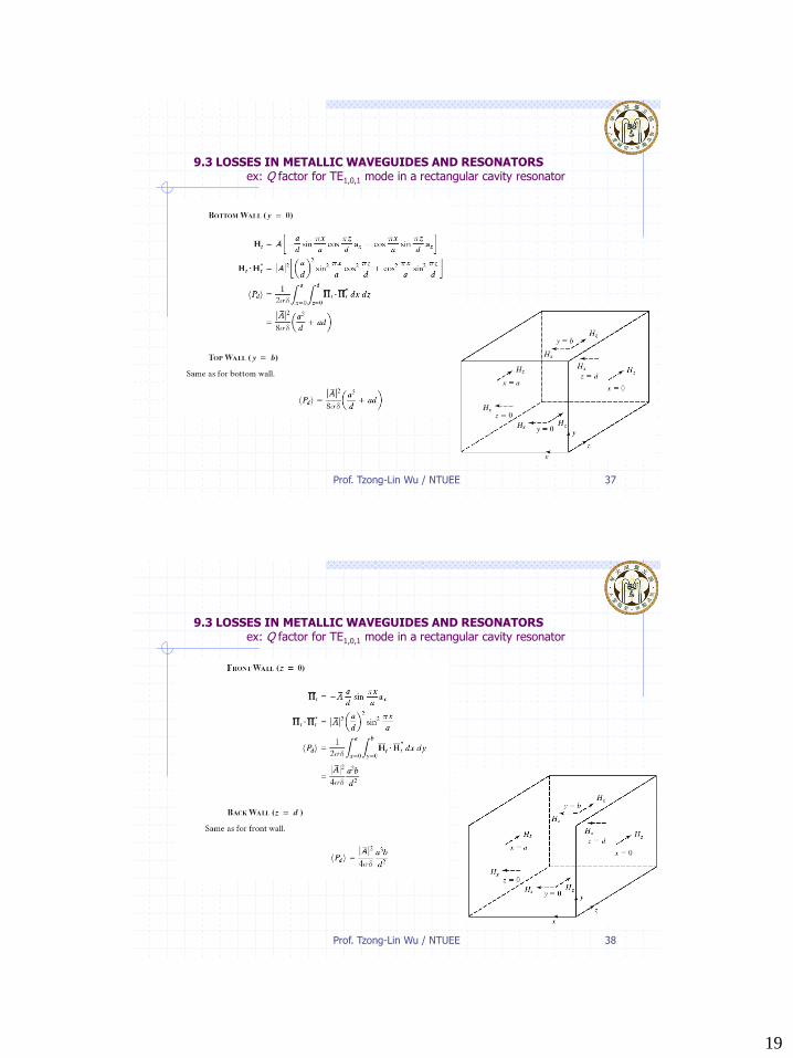
9.3 LOSSES IN METALLIC WAVEGUIDES AND RESONATORSex: Q factor for TE1,0,1 mode in a rectangular cavity resonator
Prof. Tzong-Lin Wu / NTUEE 38
9.3 LOSSES IN METALLIC WAVEGUIDES AND RESONATORSex: Q factor for TE1,0,1 mode in a rectangular cavity resonator
20
Prof. Tzong-Lin Wu / NTUEE 39
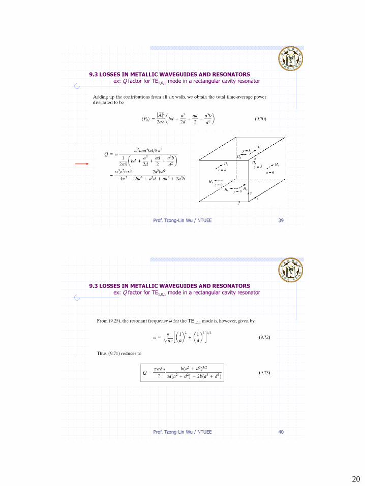
9.3 LOSSES IN METALLIC WAVEGUIDES AND RESONATORSex: Q factor for TE1,0,1 mode in a rectangular cavity resonator
Prof. Tzong-Lin Wu / NTUEE 40
9.3 LOSSES IN METALLIC WAVEGUIDES AND RESONATORSex: Q factor for TE1,0,1 mode in a rectangular cavity resonator