Embed Size (px)
Citation preview
See last page for copyright and document information, File: Reeve_RPi_WLANSetup.doc, Page 1
Setup Wireless LAN (WLAN) on the Raspberry Pi
1. Introduction
Adding a wireless LAN connection to the Raspberry Pi (RPi) requires only a USB wireless access device (also
called WLAN dongle and Wi-Fi dongle) and some changes to the network interface configurations. The following
steps assume the RPi is initially connected to the LAN through a wired Ethernet cable. DO NOT plugin the Wi-Fi
dongle until instructed to do so. As you go through the following steps, take screenshots before and after
making changes – this will help in case you make a mistake and need to reverse your changes.
A Wi-Fi dongle derives power from the RPi USB port and this power is in addition to that required by the RPi
itself. A typical Wi-Fi dongle adds about 30 mA to the RPi load current. A power supply that is adequate for the
RPi alone may not be adequate for the RPi and a Wi-Fi dongle. A power supply with at least 5 W capacity (≥ 1 A
at 5 Vdc) should be used. The dongle should be plugged into the USB port BEFORE power is applied to the RPi;
otherwise, the RPi may spontaneously reboot because of the momentary voltage drop on its power bus, possibly
resulting in program corruption. This design deficiency is especially apparent in the RPi model B but much less so
in the model B+.
2. WLAN Dongle
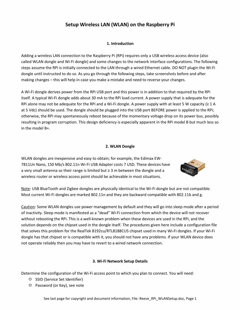
WLAN dongles are inexpensive and easy to obtain; for example, the Edimax EW-
7811Un Nano, 150 Mb/s 802.11n Wi-Fi USB Adapter costs 7 USD. These devices have
a very small antenna so their range is limited but ≥ 3 m between the dongle and a
wireless router or wireless access point should be achievable in most situations.
Note: USB BlueTooth and Zigbee dongles are physically identical to the Wi-Fi dongle but are not compatible.
Most current Wi-Fi dongles are marked 802.11n and they are backward compatible with 802.11b and g.
Caution: Some WLAN dongles use power management by default and they will go into sleep mode after a period
of inactivity. Sleep mode is manifested as a “dead” Wi-Fi connection from which the device will not recover
without rebooting the RPi. This is a well-known problem when these devices are used in the RPi, and the
solution depends on the chipset used in the dongle itself. The procedures given here include a configuration file
that solves this problem for the RealTek 8192cu/RTL8188CUS chipset used in many Wi-Fi dongles. If your Wi-Fi
dongle has that chipset or is compatible with it, you should not have any problems. If your WLAN device does
not operate reliably then you may have to revert to a wired network connection.
3. Wi-Fi Network Setup Details
Determine the configuration of the Wi-Fi access point to which you plan to connect. You will need:
SSID (Service Set Identifier)
Password (or Key), see note
See last page for copyright and document information, File: Reeve_RPi_WLANSetup.doc, Page 2
Encryption type and method (for example, WPA and TKIP shared-key encryption), see note
Note: If the network to be connected is unsecured, only the SSID (or ESSID) needs to be known.
Procedures for determining these parameters vary widely so you will need to refer to your wireless access point
user guide or do online research. The setup described in the following paragraphs assumes your Wi-Fi network
broadcasts the SSID.
4. Setup W-Fi Configuration
Do not yet plug in the Wi-Fi dongle. Log into the RPi and enter the following:sudo nano /etc/network/interfaces
The default settings for the interfaces have changed over time. The details for two scenarios are described
below. Use the one that matches your default settings for the network interfaces.
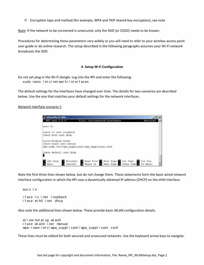
Network interface scenario 1:
Note the first three lines shown below, but do not change them. These statements form the basic wired network
interface configuration in which the RPi uses a dynamically obtained IP address (DHCP) on the eth0 interface:
auto lo
iface lo inet loopbackiface eth0 inet dhcp
Also note the additional lines shown below. These provide basic WLAN configuration details.
allow-hotplug wlan0iface wlan0 inet manualwpa-roam /etc/wpa_supplicant/wpa_supplicant.conf
These lines must be edited for both secured and unsecured networks. Use the keyboard arrow keys to navigate.
See last page for copyright and document information, File: Reeve_RPi_WLANSetup.doc, Page 3
Unsecured network: Change manual to dhcp in the second line and comment out the third line. Add a fourth
line with the ESSID for the unsecured network. When done, the group of lines should look like this:
allow-hotplug wlan0
iface wlan0 inet dhcp
# wpa-roam /etc/wpa_supplicant/wpa_supplicant.conf
wireless-essid Your_NETWORK_Name
Be sure to replace Your_NETWORK_Name with the actual SSID for the unsecured network; do not use quotation
marks.
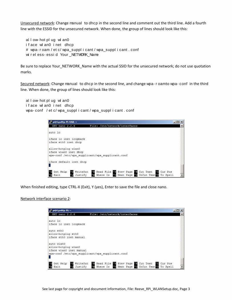
Secured network: Change manual to dhcp in the second line, and change wpa-roam to wpa-conf in the third
line. When done, the group of lines should look like this:
allow-hotplug wlan0
iface wlan0 inet dhcp
wpa-conf /etc/wpa_supplicant/wpa_supplicant.conf
When finished editing, type CTRL-X (Exit), Y (yes), Enter to save the file and close nano.
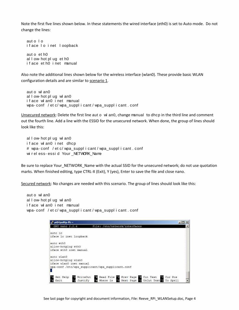
Network interface scenario 2:
See last page for copyright and document information, File: Reeve_RPi_WLANSetup.doc, Page 4
Note the first five lines shown below. In these statements the wired interface (eth0) is set to Auto mode. Do not
change the lines:
auto loiface lo inet loopback
auto eth0allow-hotplug eth0iface eth0 inet manual
Also note the additional lines shown below for the wireless interface (wlan0). These provide basic WLAN
configuration details and are similar to scenario 1.
auto wlan0allow-hotplug wlan0iface wlan0 inet manualwpa-conf /etc/wpa_supplicant/wpa_supplicant.conf
Unsecured network: Delete the first line auto wlan0, change manual to dhcp in the third line and comment
out the fourth line. Add a line with the ESSID for the unsecured network. When done, the group of lines should
look like this:
allow-hotplug wlan0
iface wlan0 inet dhcp
# wpa-conf /etc/wpa_supplicant/wpa_supplicant.conf
wireless-essid Your_NETWORK_Name
Be sure to replace Your_NETWORK_Name with the actual SSID for the unsecured network; do not use quotation
marks. When finished editing, type CTRL-X (Exit), Y (yes), Enter to save the file and close nano.
Secured network: No changes are needed with this scenario. The group of lines should look like this:
auto wlan0
allow-hotplug wlan0
iface wlan0 inet manual
wpa-conf /etc/wpa_supplicant/wpa_supplicant.conf
See last page for copyright and document information, File: Reeve_RPi_WLANSetup.doc, Page 5
When finished editing, type CTRL-X (Exit), Y (yes), Enter to save the file and close nano. Now, for a secured
network, it is necessary to setup the WLAN configuration as described in the following paragraphs.
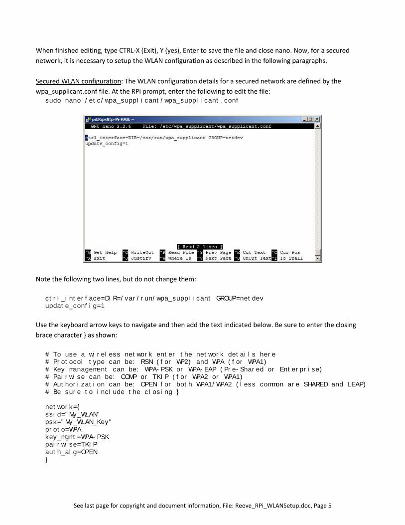
Secured WLAN configuration: The WLAN configuration details for a secured network are defined by the
wpa_supplicant.conf file. At the RPi prompt, enter the following to edit the file:sudo nano /etc/wpa_supplicant/wpa_supplicant.conf
Note the following two lines, but do not change them:
ctrl_interface=DIR=/var/run/wpa_supplicant GROUP=netdevupdate_config=1
Use the keyboard arrow keys to navigate and then add the text indicated below. Be sure to enter the closing
brace character } as shown:
# To use a wireless network enter the network details here# Protocol type can be: RSN (for WP2) and WPA (for WPA1)# Key management can be: WPA-PSK or WPA-EAP (Pre-Shared or Enterprise)# Pairwise can be: COMP or TKIP (for WPA2 or WPA1)# Authorization can be: OPEN for both WPA1/WPA2 (less common are SHARED and LEAP)# Be sure to include the closing }
network={ssid="My_WLAN"psk="My_WLAN_Key"proto=WPAkey_mgmt=WPA-PSKpairwise=TKIPauth_alg=OPEN}
See last page for copyright and document information, File: Reeve_RPi_WLANSetup.doc, Page 6
Note that most of text to be entered are comments indicated by the # character at the beginning of the line.
These comments cover the most common situations. If additional information is needed, exit the nano editor
and at the prompt type man wpa_supplicant. This will open the manual for the wpa_supplicant file, which
will explain all of the options and requirements for its use.
The first two parameters above, ssid and psk, are the SSID and PASSWORD values, and proto, key_mgmt,
pairwise and auth_alg are the Encryption type and method that you obtained above from your wireless
network. Use the # character to include the comments and change the values shown to match your network
details.
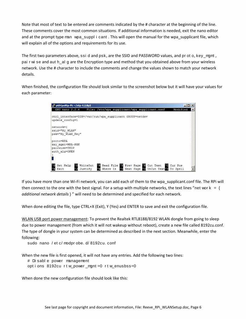
When finished, the configuration file should look similar to the screenshot below but it will have your values for
each parameter:
If you have more than one Wi-Fi network, you can add each of them to the wpa_supplicant.conf file. The RPi will
then connect to the one with the best signal. For a setup with multiple networks, the text lines “network = {
additional network details }” will need to be determined and specified for each network.
When done editing the file, type CTRL+X (Exit), Y (Yes) and ENTER to save and exit the configuration file.
WLAN USB port power management: To prevent the Realtek RTL8188/8192 WLAN dongle from going to sleep
due to power management (from which it will not wakeup without reboot), create a new file called 8192cu.conf.
The type of dongle in your system can be determined as described in the next section. Meanwhile, enter the
following:sudo nano /etc/modprobe.d/8192cu.conf
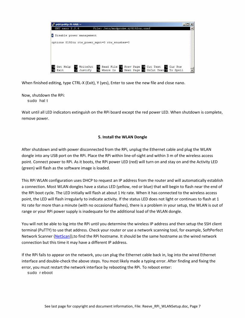
When the new file is first opened, it will not have any entries. Add the following two lines:# Disable power management
options 8192cu rtw_power_mgnt=0 rtw_enusbss=0
When done the new configuration file should look like this:
See last page for copyright and document information, File: Reeve_RPi_WLANSetup.doc, Page 7
When finished editing, type CTRL-X (Exit), Y (yes), Enter to save the new file and close nano.
Now, shutdown the RPi:sudo halt
Wait until all LED indicators extinguish on the RPi board except the red power LED. When shutdown is complete,
remove power.
5. Install the WLAN Dongle
After shutdown and with power disconnected from the RPi, unplug the Ethernet cable and plug the WLAN
dongle into any USB port on the RPi. Place the RPi within line-of-sight and within 3 m of the wireless access
point. Connect power to RPi. As it boots, the RPi power LED (red) will turn on and stay on and the Activity LED
(green) will flash as the software image is loaded.
This RPi WLAN configuration uses DHCP to request an IP address from the router and will automatically establish
a connection. Most WLAN dongles have a status LED (yellow, red or blue) that will begin to flash near the end of
the RPi boot cycle. The LED initially will flash at about 1 Hz rate. When it has connected to the wireless access
point, the LED will flash irregularly to indicate activity. If the status LED does not light or continues to flash at 1
Hz rate for more than a minute (with no occasional flashes), there is a problem in your setup, the WLAN is out of
range or your RPi power supply is inadequate for the additional load of the WLAN dongle.
You will not be able to log into the RPi until you determine the wireless IP address and then setup the SSH client
terminal (PuTTY) to use that address. Check your router or use a network scanning tool, for example, SoftPerfect
Network Scanner {NetScan}),to find the RPi hostname. It should be the same hostname as the wired network
connection but this time it may have a different IP address.
If the RPi fails to appear on the network, you can plug the Ethernet cable back in, log into the wired Ethernet
interface and double-check the above steps. You most likely made a typing error. After finding and fixing the
error, you must restart the network interface by rebooting the RPi. To reboot enter:sudo reboot
See last page for copyright and document information, File: Reeve_RPi_WLANSetup.doc, Page 8
Disconnect the wired Ethernet cable and log into the wireless interface using the wireless IP address.
Remember, do not insert or remove the WLAN dongle with power applied to the RPi, but it is okay to remove
and install the wired LAN cable with power on.
It is possible to use both the wired and wireless LAN interfaces at the same time; however, It is recommended
that one or the other be used and not simultaneously. If wired LAN interface is to be used, remove the WLAN
dongle (with RPi power off). If wireless LAN is to be used, remove the wired LAN cable. No changes are required
to RPi configuration files.
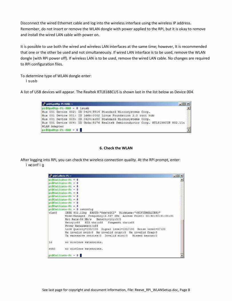
To determine type of WLAN dongle enter:lsusb
A list of USB devices will appear. The Realtek RTL8188CUS is shown last in the list below as Device 004.
6. Check the WLAN
After logging into RPi, you can check the wireless connection quality. At the RPi prompt, enter:iwconfig
See last page for copyright and document information, File: Reeve_RPi_WLANSetup.doc, Page 9
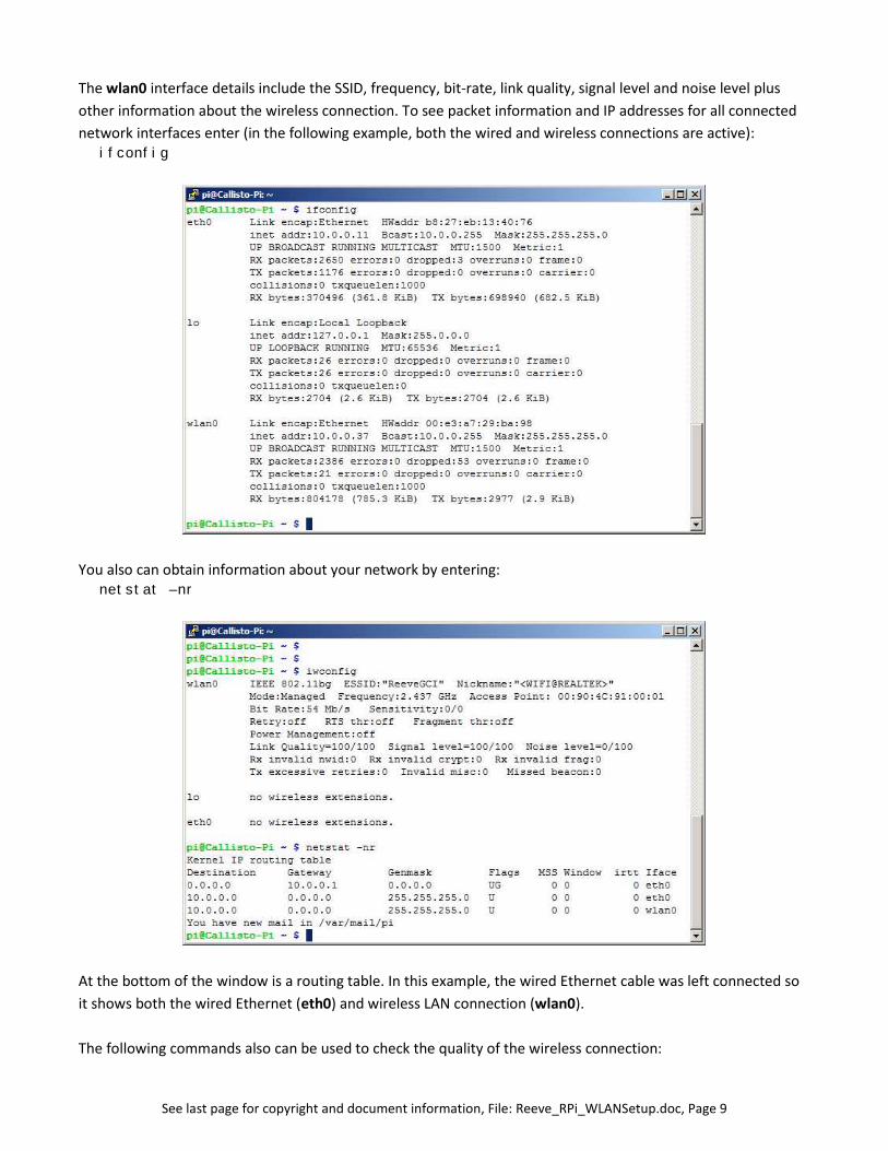
The wlan0 interface details include the SSID, frequency, bit-rate, link quality, signal level and noise level plus
other information about the wireless connection. To see packet information and IP addresses for all connected
network interfaces enter (in the following example, both the wired and wireless connections are active):ifconfig
You also can obtain information about your network by entering:netstat –nr
At the bottom of the window is a routing table. In this example, the wired Ethernet cable was left connected so
it shows both the wired Ethernet (eth0) and wireless LAN connection (wlan0).
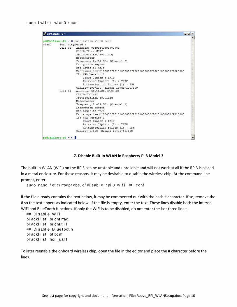
The following commands also can be used to check the quality of the wireless connection:
See last page for copyright and document information, File: Reeve_RPi_WLANSetup.doc, Page 10
sudo iwlist wlan0 scan
7. Disable Built-In WLAN in Raspberry Pi B Model 3
The built-in WLAN (WiFi) on the RPi3 can be unstable and unreliable and will not work at all if the RPI3 is placed
in a metal enclosure. For these reasons, it may be desirable to disable the wireless chip. At the command line
prompt, entersudo nano /etc/modprobe.d/disable_rpi3_wifi_bt.conf
If the file already contains the text below, it may be commented out with the hash # character. If so, remove the
# so the text appers as indicated below. If the file is empty, enter the text. These lines disable both the internal
WiFi and BlueTooth functions. If only the WiFi is to be disabled, do not enter the last three lines:## Disable WiFi
blacklist brcmfmac
blacklist brcmutil
## Disable BlueTooth
blacklist btbcm
blacklist hci_uart
To later reenable the onboard wireless chip, open the file in the editor and place the # character before the
lines.
See last page for copyright and document information, File: Reeve_RPi_WLANSetup.doc, Page 11
8. Web Links
{NetScan} https://www.softperfect.com/products/networkscanner/
Nano Editor
Use arrow keys to move the cursor. Move cursor to beginning of text to be copied or cut.
To select text, ALT-a and then use arrow keys
To copy selected text, ALT-^
To cut selected text, CTRL-k
To paste selected text, CTRL-u
See last page for copyright and document information, File: Reeve_RPi_WLANSetup.doc, Page 12
Document information
Author: Whitham D. Reeve
Copyright: © 2015, 2016, 2017 W. Reeve
Revision: 0.0 (Original, derived from Callisto-Pi Setup Guide, 13 Feb 2015)
0.1 (Cleaned up, removed references to Callisto-Pi, 17 Feb 2015)
0.2 (WLAN query and corrected WLAN supplicant, 05 Mar 2015)
0.3 (Updated power requirements, 11 Mar 2015)
0.4 (Added unsecured network setup and corrected supplicant, 21 Jun 2015)
1.0 (Distribution, 21 Jun 2015)
1.1 (Changed sect. 4 for current defaults, 12 Oct 2015)
1.2 (Added disable RPi3 onboard wireless, 13 Aug 2016)