Embed Size (px)
Citation preview
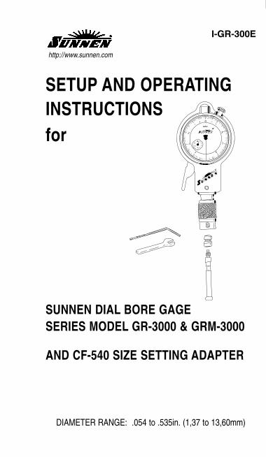
I-GR-300E
SETUP AND OPERATING INSTRUCTIONSfor
SUNNEN DIAL BORE GAGESERIES MODEL GR-3000 & GRM-3000
AND CF-540 SIZE SETTING ADAPTER
DIAMETER RANGE: .054 to .535in. (1,37 to 13,60mm)
http://www.sunnen.com
ii
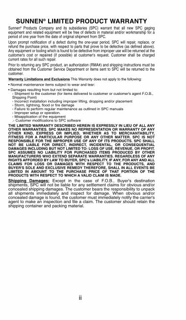
SUNNEN® LIMITED PRODUCT WARRANTYSunnen® Products Company and its subsidiaries (SPC) warrant that all new SPC gagingequipment and related equipment will be free of defects in material and/or workmanship for aperiod of one year from the date of original shipment from SPC.Upon prompt notification of a defect during the one-year period, SPC will repair, replace, orrefund the purchase price, with respect to parts that prove to be defective (as defined above).Any equipment or tooling which is found to be defective from improper use will be returned at thecustomer's cost or repaired (if possible) at customer's request. Customer shall be chargedcurrent rates for all such repair.Prior to returning any SPC product, an authorization (RMA#) and shipping instructions must beobtained from the Customer Service Department or items sent to SPC will be returned to thecustomer.Warranty Limitations and Exclusions This Warranty does not apply to the following:
• Normal maintenance items subject to wear and tear:• Damages resulting from but not limited to:
› Shipment to the customer (for items delivered to customer or customer's agent F.O.B.,Shipping Point)› Incorrect installation including improper lifting, dropping and/or placement› Storm, lightning, flood or fire damage› Failure to perform regular maintenance as outlined in SPC manuals› Improper setup or operation.› Misapplication of the equipment.› Customer modifications to SPC software
THE LIMITED WARRANTY DESCRIBED HEREIN IS EXPRESSLY IN LIEU OF ALL ANYOTHER WARRANTIES. SPC MAKES NO REPRESENTATION OR WARRANTY OF ANYOTHER KIND, EXPRESS OR IMPLIED, WHETHER AS TO MERCHANTABILITY,FITNESS FOR A PARTICULAR PURPOSE OR ANY OTHER MATTER. SPC IS NOTRESPONSIBLE FOR THE IMPROPER USE OF ANY OF ITS PRODUCTS. SPC SHALLNOT BE LIABLE FOR DIRECT, INDIRECT, INCIDENTAL, OR CONSEQUENTIALDAMAGES INCLUDING BUT NOT LIMITED TO: LOSS OF USE, REVENUE, OR PROFIT.SPC ASSUMES NO LIABILITY FOR PURCHASED ITEMS PRODUCED BY OTHERMANUFACTURERS WHO EXTEND SEPARATE WARRANTIES. REGARDLESS OF ANYRIGHTS AFFORDED BY LAW TO BUYER, SPC's LIABILITY, IF ANY, FOR ANY AND ALLCLAIMS FOR LOSS OR DAMAGES WITH RESPECT TO THE PRODUCTS, ANDBUYER'S SOLE AND EXCLUSIVE REMEDY THEREFORE, SHALL IN ALL EVENTS BELIMITED IN AMOUNT TO THE PURCHASE PRICE OF THAT PORTION OF THEPRODUCTS WITH RESPECT TO WHICH A VALID CLAIM IS MADE.
Shipping Damages: Except in the case of F.O.B., Buyer's destinationshipments, SPC will not be liable for any settlement claims for obvious and/orconcealed shipping damages. The customer bears the responsibility to unpackall shipments immediately and inspect for damage. When obvious and/orconcealed damage is found, the customer must immediately notify the carrier'sagent to make an inspection and file a claim. The customer should retain theshipping container and packing material.
iii
TABLE OF CONTENTSPage
Limited Product Warranty . . . . . . . . . . . . . . . . . . . . . iiTable of Contents . . . . . . . . . . . . . . . . . . . . . . . . . . . iiiGeneral Information . . . . . . . . . . . . . . . . . Back CoverGENERAL DESCRIPTIONGeneral . . . . . . . . . . . . . . . . . . . . . . . . . . . . . . . . . . 1Brief Description . . . . . . . . . . . . . . . . . . . . . . . . . . . . 3
Retractable Dial Bore Gage . . . . . . . . . . . . . . . . . . 3Size Setting Adapter . . . . . . . . . . . . . . . . . . . . . . . 5Setting Fixture . . . . . . . . . . . . . . . . . . . . . . . . . . . . 7
SETUP & OPERATIONGeneral . . . . . . . . . . . . . . . . . . . . . . . . . . . . . . . . . . 9Set Gage . . . . . . . . . . . . . . . . . . . . . . . . . . . . . . . . . 9Gage Workpiece . . . . . . . . . . . . . . . . . . . . . . . . . . 17
“SUNNEN AND THE SUNNEN LOGO ARE REGISTERED TRADEMARKS OF SUNNEN PRODUCTS COMPANY.”
©COPYRIGHT SUNNEN® PRODUCTS COMPANY 2006, ALL RIGHTS RESERVED

NOTES
iv
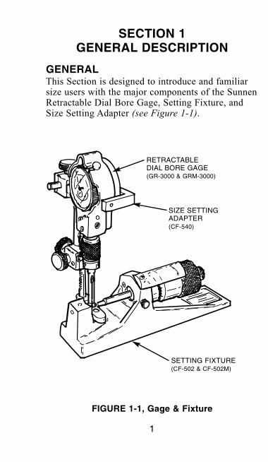
GENERALThis Section is designed to introduce and familiarsize users with the major components of the SunnenRetractable Dial Bore Gage, Setting Fixture, andSize Setting Adapter (see Figure 1-1).
SECTION 1GENERAL DESCRIPTION
FIGURE 1-1, Gage & Fixture
RETRACTABLEDIAL BORE GAGE (GR-3000 & GRM-3000)
SIZE SETTINGADAPTER (CF-540)
SETTING FIXTURE (CF-502 & CF-502M)
1
2
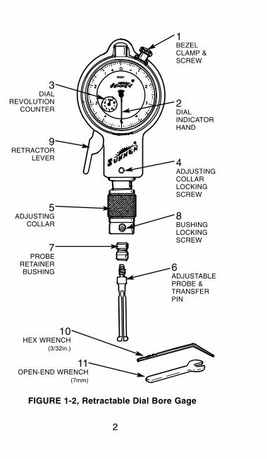
FIGURE 1-2, Retractable Dial Bore Gage
1 BEZELCLAMP &SCREW
2 DIALINDICATORHAND
4 ADJUSTINGCOLLARLOCKINGSCREW
3 DIAL
REVOLUTIONCOUNTER
9 RETRACTOR
LEVER
5 ADJUSTING
COLLAR
7 PROBE
RETAINERBUSHING
8 BUSHINGLOCKINGSCREW
6 ADJUSTABLEPROBE &TRANSFERPIN
10 HEX WRENCH
(3/32in.)
11 OPEN-END WRENCH
(7mm)
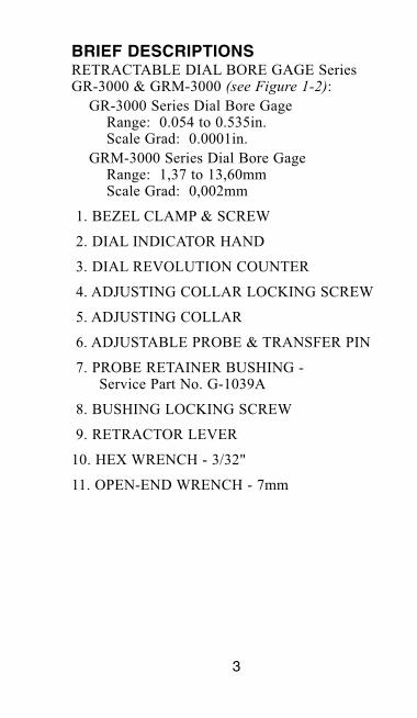
BRIEF DESCRIPTIONSRETRACTABLE DIAL BORE GAGE Series GR-3000 & GRM-3000 (see Figure 1-2):
GR-3000 Series Dial Bore Gage Range: 0.054 to 0.535in.Scale Grad: 0.0001in.
GRM-3000 Series Dial Bore GageRange: 1,37 to 13,60mm Scale Grad: 0,002mm
1. BEZEL CLAMP & SCREW
2. DIAL INDICATOR HAND
3. DIAL REVOLUTION COUNTER
4. ADJUSTING COLLAR LOCKING SCREW
5. ADJUSTING COLLAR
6. ADJUSTABLE PROBE & TRANSFER PIN
7. PROBE RETAINER BUSHING -Service Part No. G-1039A
8. BUSHING LOCKING SCREW
9. RETRACTOR LEVER
10. HEX WRENCH - 3/32"
11. OPEN-END WRENCH - 7mm
3
4
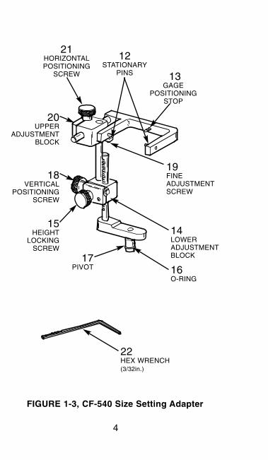
FIGURE 1-3, CF-540 Size Setting Adapter
21HORIZONTALPOSITIONING
SCREW
20 UPPER
ADJUSTMENTBLOCK
13GAGE
POSITIONINGSTOP
12STATIONARY
PINS
19FINEADJUSTMENTSCREW
14LOWERADJUSTMENTBLOCK
18 VERTICAL
POSITIONINGSCREW
15 HEIGHT
LOCKINGSCREW
17 PIVOT 16
O-RING
22 HEX WRENCH(3/32in.)
SIZE SETTING ADAPTER Model CF-540 (see Figure 1-3):
CF-540 Size Setting AdapterFor use with Sunnen GR-3000 and GRM-3000 Series Retractable Dial BoreGages
12. STATIONARY PINS
13. GAGE POSITIONING STOP
14. LOWER ADJUSTMENT BLOCK
15. HEIGHT LOCKING SCREW
16. "O" RINGS - Service Part No. BP-10300A(Package of 2)
17. PIVOT
18. VERTICAL POSITIONING SCREW
19. FINE ADJUSTMENT SCREW
20. UPPER ADJUSTMENT BLOCK
21. HORIZONTAL POSITIONING SCREW
22. HEX WRENCH - 3/32in.
5
6
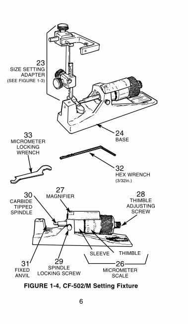
FIGURE 1-4, CF-502/M Setting Fixture
32 HEX WRENCH(3/32in.)
24 BASE
33 MICROMETER
LOCKINGWRENCH
28THIMBLE
ADJUSTINGSCREW
27MAGNIFIER30
CARBIDETIPPED
SPINDLE
31 FIXEDANVIL
29SPINDLE
LOCKING SCREW
26MICROMETER
SCALE
SLEEVE THIMBLE
23 SIZE SETTING
ADAPTER(SEE FIGURE 1-3)
SETTING FIXTURE Models CF-502 & CF-502M(see Figure 1-4):
CF-502 Setting FixtureRange: 0 to 2.000in.Scale Grad: 0.0001in.
CF-502M Metric Setting Fixture Range: 0 to 50mm Scale Grad: 0,002mm
23. SIZE SETTING ADAPTER - Refer to Figure 1-3
24. BASE - One-piece, stress-relieved cast iron base frame
25. MICROMETER HEAD - With Micrometer Scale and Carbide Tipped Spindle
26. MICROMETER SCALE - Comprised of an outer Thimble and inner Sleeve; graduated in 0.0001in. or 0,002mm
27. MAGNIFIER - For easier reading of the Micrometer Scale
28. THIMBLE ADJUSTING SCREW - Locks setting in fixture
29. SPINDLE LOCKING SCREW - Locks spindle
30. CARBIDE TIPPED SPINDLE - Carbide tipped for long life
31. FIXED ANVIL - Use for aligning and positioning Probe Tip
32. HEX WRENCH - 3/32in.
33. MICROMETER LOCKING WRENCH-Use for tightening jam Nut or Thimble Adjusting Screw
34. STORAGE CASE - Not shown
7
8
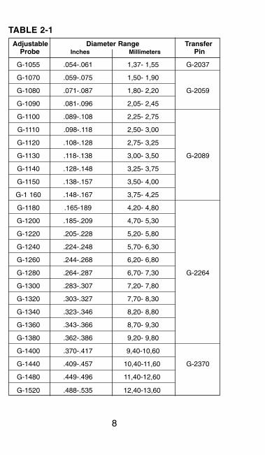
TABLE 2-1
Adjustable Diameter Range TransferProbe Inches Millimeters Pin
G-1055 .054-.061 1,37- 1,55 G-2037
G-1070 .059-.075 1,50- 1,90
G-1080 .071-.087 1,80- 2,20 G-2059
G-1090 .081-.096 2,05- 2,45
G-1100 .089-.108 2,25- 2,75
G-1110 .098-.118 2,50- 3,00
G-1120 .108-.128 2,75- 3,25
G-1130 .118-.138 3,00- 3,50 G-2089
G-1140 .128-.148 3,25- 3,75
G-1150 .138-.157 3,50- 4,00
G-1 160 .148-.167 3,75- 4,25
G-1180 .165-189 4,20- 4,80
G-1200 .185-.209 4,70- 5,30
G-1220 .205-.228 5,20- 5,80
G-1240 .224-.248 5,70- 6,30
G-1260 .244-.268 6,20- 6,80
G-1280 .264-.287 6,70- 7,30 G-2264
G-1300 .283-.307 7,20- 7,80
G-1320 .303-.327 7,70- 8,30
G-1340 .323-.346 8,20- 8,80
G-1360 .343-.366 8,70- 9,30
G-1380 .362-.386 9,20- 9,80
G-1400 .370-.417 9,40-10,60
G-1440 .409-.457 10,40-11,60 G-2370
G-1480 .449-.496 11,40-12,60
G-1520 .488-.535 12,40-13,60
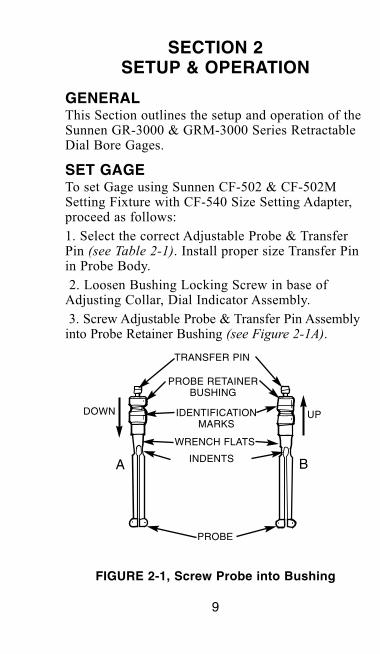
GENERALThis Section outlines the setup and operation of theSunnen GR-3000 & GRM-3000 Series RetractableDial Bore Gages.
SET GAGETo set Gage using Sunnen CF-502 & CF-502MSetting Fixture with CF-540 Size Setting Adapter,proceed as follows:
1. Select the correct Adjustable Probe & TransferPin (see Table 2-1). Install proper size Transfer Pinin Probe Body.
2. Loosen Bushing Locking Screw in base ofAdjusting Collar, Dial Indicator Assembly.
3. Screw Adjustable Probe & Transfer Pin Assemblyinto Probe Retainer Bushing (see Figure 2-1A).
9
SECTION 2SETUP & OPERATION
FIGURE 2-1, Screw Probe into Bushing
TRANSFER PIN
PROBE RETAINERBUSHING
IDENTIFICATIONMARKS
WRENCH FLATS
INDENTS
PROBE
DOWN UP
BA
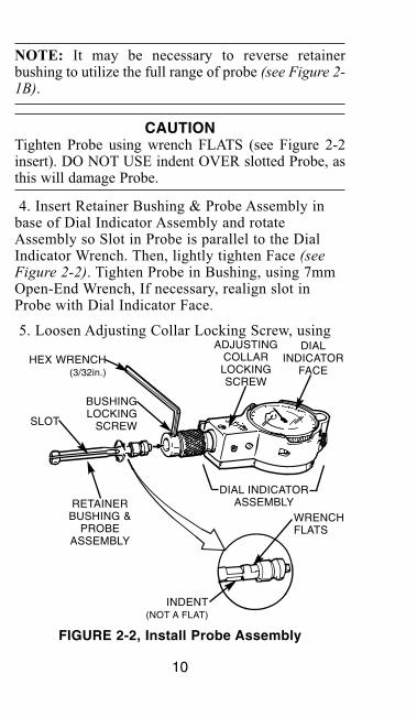
NOTE: It may be necessary to reverse retainerbushing to utilize the full range of probe (see Figure 2-1B).
CAUTIONTighten Probe using wrench FLATS (see Figure 2-2insert). DO NOT USE indent OVER slotted Probe, asthis will damage Probe.
4. Insert Retainer Bushing & Probe Assembly inbase of Dial Indicator Assembly and rotateAssembly so Slot in Probe is parallel to the DialIndicator Wrench. Then, lightly tighten Face (seeFigure 2-2). Tighten Probe in Bushing, using 7mmOpen-End Wrench, If necessary, realign slot inProbe with Dial Indicator Face.
5. Loosen Adjusting Collar Locking Screw, using
10
FIGURE 2-2, Install Probe Assembly
RETAINERBUSHING &
PROBEASSEMBLY
HEX WRENCH(3/32in.)
BUSHINGLOCKING
SCREWSLOT
INDENT(NOT A FLAT)
DIALINDICATOR
FACE
ADJUSTINGCOLLARLOCKINGSCREW
DIAL INDICATORASSEMBLY
WRENCHFLATS
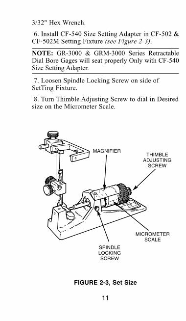
3/32" Hex Wrench.
6. Install CF-540 Size Setting Adapter in CF-502 &CF-502M Setting Fixture (see Figure 2-3).
NOTE: GR-3000 & GRM-3000 Series RetractableDial Bore Gages will seat properly Only with CF-540Size Setting Adapter.
7. Loosen Spindle Locking Screw on side ofSetTing Fixture.
8. Turn Thimble Adjusting Screw to dial in Desiredsize on the Micrometer Scale.
11
FIGURE 2-3, Set Size
SPINDLELOCKINGSCREW
MICROMETERSCALE
THIMBLEADJUSTING
SCREW
MAGNIFIER
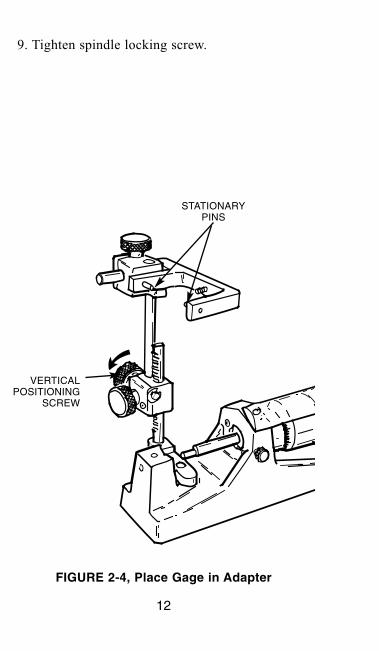
9. Tighten spindle locking screw.
12
FIGURE 2-4, Place Gage in Adapter
STATIONARYPINS
VERTICALPOSITIONING
SCREW
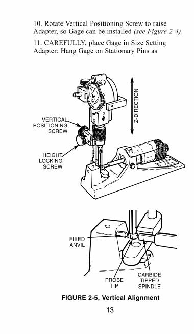
10. Rotate Vertical Positioning Screw to raiseAdapter, so Gage can be installed (see Figure 2-4).
11. CAREFULLY, place Gage in Size SettingAdapter: Hang Gage on Stationary Pins as
13
FIGURE 2-5, Vertical Alignment
CARBIDETIPPED
SPINDLEPROBE
TIP
FIXEDANVIL
HEIGHTLOCKING
SCREW
VERTICALPOSITIONING
SCREWZ
-DIR
EC
TIO
N
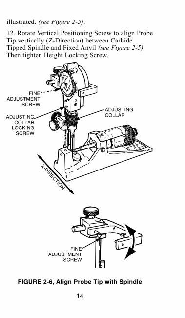
illustrated. (see Figure 2-5).
12. Rotate Vertical Positioning Screw to align ProbeTip vertically (Z-Direction) between CarbideTipped Spindle and Fixed Anvil (see Figure 2-5).Then tighten Height Locking Screw.
14
FIGURE 2-6, Align Probe Tip with Spindle
FINEADJUSTMENT
SCREW
X-DIRECTION
ADJUSTINGCOLLAR
LOCKINGSCREW
FINEADJUSTMENT
SCREW
ADJUSTINGCOLLAR
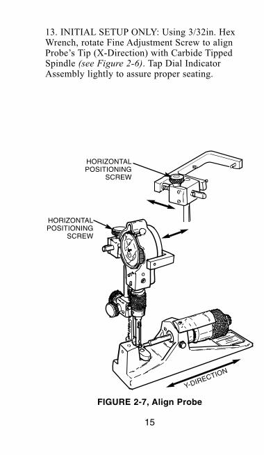
13. INITIAL SETUP ONLY: Using 3/32in. HexWrench, rotate Fine Adjustment Screw to alignProbe’s Tip (X-Direction) with Carbide TippedSpindle (see Figure 2-6). Tap Dial IndicatorAssembly lightly to assure proper seating.
15
FIGURE 2-7, Align Probe
HORIZONTALPOSITIONING
SCREW
HORIZONTALPOSITIONING
SCREW
Y-DIRECTION
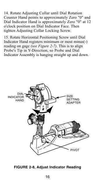
14. Rotate Adjusting Collar until Dial RotationCounter Hand points to approximately Zero "0" andDial Indicator Hand is approximately Zero "0" at 12o'clock position on Dial Indicator Face. Thentighten Adjusting Collar Locking Screw.
15. Rotate Horizontal Positioning Screw until DialIndicator Hand registers minimum or most minus(-)reading on gage (see Figure 2-7). This is to alignProbe's Tip in Y-Direction, so Probe and DialIndicator Assembly is hanging straight up and down.
16
FIGURE 2-8, Adjust Indicator Reading
DIALINDICATOR
HANDSIZESETTINGADAPTER
PIVOT
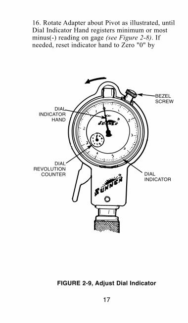
16. Rotate Adapter about Pivot as illustrated, untilDial Indicator Hand registers minimum or mostminus(-) reading on gage (see Figure 2-8). Ifneeded, reset indicator hand to Zero "0" by
17
FIGURE 2-9, Adjust Dial Indicator
DIALINDICATOR
DIALINDICATOR
HAND
BEZELSCREW
DIALREVOLUTION
COUNTER
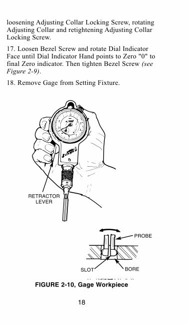
loosening Adjusting Collar Locking Screw, rotatingAdjusting Collar and retightening Adjusting CollarLocking Screw.
17. Loosen Bezel Screw and rotate Dial IndicatorFace until Dial Indicator Hand points to Zero "0" tofinal Zero indicator. Then tighten Bezel Screw (seeFigure 2-9).
18. Remove Gage from Setting Fixture.
18
FIGURE 2-10, Gage Workpiece
RETRACTORLEVER
PROBE
BORESLOT

GAGE WORKPIECE1. Squeeze the Retractor Lever and insert Probe in
bore (retracting action minimizes Probe wear).
19

2. Release Lever and rock Gage in bore as illustrated, to obtain the est indicator reading (seeFigure 2-10).
NOTE: Explore various parts of the bore to obtainsize, taper, and roundness data.
3. Squeeze Retractor Lever and remove Probe fromWorkpiece.
4. Repeat gaging operation for each Workpiece.
20

NOTES
21

“SUNNEN AND THE SUNNEN LOGO ARE REGISTERED TRADEMARKS OF SUNNEN PRODUCTS COMPANY.”
SUNNEN PRODUCTS COMPANY7910 Manchester Road. • St. Louis, MO 63143 U.S.A. • Ph: 314-781-2100 • Fax: 314-781-2268U.S.A. Toll-Free Sales and Service – Auto: 1-800-772-2878 • Ind: 1-800-325-3670International Division Fax: 314-781-6128http://www.sunnen.com
PRINTED IN U.S.A. 0606 ©COPYRIGHT SUNNEN® PRODUCTS COMPANY 2006, ALL RIGHTS RESERVED
GENERAL INFORMATIONThe Sunnen® equipment has been designed and engineered for a wide variety of parts within thecapacity and limitation of the equipment. With proper care and maintenance this equipment willgive years of service.READ THE FOLLOWING INSTRUCTIONS CAREFULLY AND THOROUGHLY BEFORESETTING UP OR OPERATING.Sunnen Technical Service Department is available to provide telephone assistance forinstallation, programming, & troubleshooting of your Sunnen equipment. All support is availableduring normal business hours, 8:00 AM to 4:30 PM Central Time. Emergency breakdown supportis available on a 24 hour / 7 day basis.Help us help you. When ordering parts, requesting information, or technical assistanceabout your equipment, please have the following information available:
• Have this manual on hand. The Customer Services Representative or Technician willrefer to it.
• Have Model Number and Serial Number.For fast service on your orders call:
Sunnen Automotive Customer Service toll free at: 1-800-772-2878Sunnen Industrial Customer Service toll free at: 1-800-325-3670Customers outside the USA, contact your local authorized Sunnen Distributor.Additional information available at: http://www.sunnen.com or e-mail: [email protected]
NOTE: Sunnen reserves the right to change or revise specifications and product design inconnection with any feature of our products contained herein. Such changes do not entitle thebuyer to corresponding changes, improvements, additions, or replacements for equipment,supplies or accessories previously sold. Information contained herein is considered to beaccurate based on available information at the time of printing. Should any discrepancy ofinformation arise, Sunnen recommends that user verify the discrepancy with Sunnen beforeproceeding.