Embed Size (px)
Citation preview
White Paper Setting up Test Benches with VT System Version 1.0 2011-04-21
Setting up Test Benches with VT System 2 / 24
2011, Vector Group White_Paper_VT_System.doc Version 1.0 of 2011-04-21
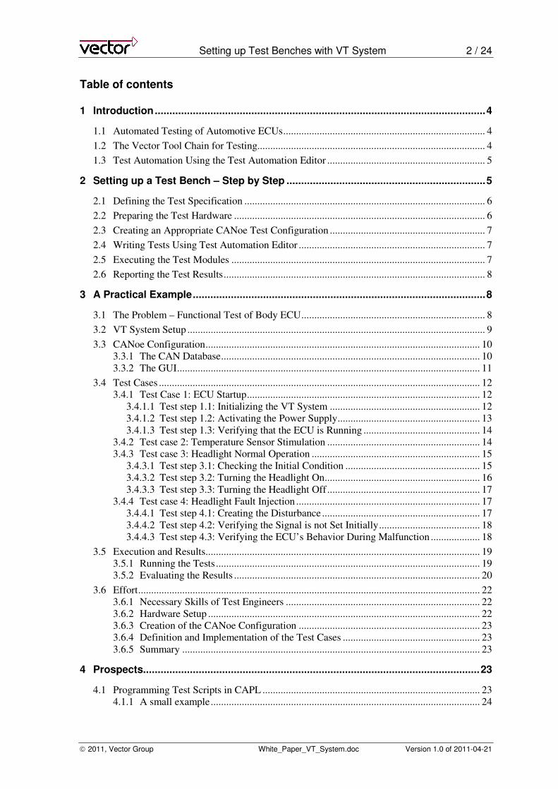
Table of contents
1 Introduction.................................................................................................................4
1.1 Automated Testing of Automotive ECUs.............................................................................. 4
1.2 The Vector Tool Chain for Testing........................................................................................ 4
1.3 Test Automation Using the Test Automation Editor ............................................................. 5
2 Setting up a Test Bench – Step by Step ....................................................................5
2.1 Defining the Test Specification ............................................................................................. 6
2.2 Preparing the Test Hardware ................................................................................................. 6
2.3 Creating an Appropriate CANoe Test Configuration ............................................................ 7
2.4 Writing Tests Using Test Automation Editor ........................................................................ 7
2.5 Executing the Test Modules .................................................................................................. 7
2.6 Reporting the Test Results..................................................................................................... 8
3 A Practical Example....................................................................................................8
3.1 The Problem – Functional Test of Body ECU....................................................................... 8
3.2 VT System Setup ................................................................................................................... 9
3.3 CANoe Configuration.......................................................................................................... 10 3.3.1 The CAN Database.................................................................................................... 10 3.3.2 The GUI..................................................................................................................... 11
3.4 Test Cases ............................................................................................................................ 12 3.4.1 Test Case 1: ECU Startup.......................................................................................... 12
3.4.1.1 Test step 1.1: Initializing the VT System .......................................................... 12 3.4.1.2 Test step 1.2: Activating the Power Supply....................................................... 13 3.4.1.3 Test step 1.3: Verifying that the ECU is Running ............................................. 14
3.4.2 Test case 2: Temperature Sensor Stimulation ........................................................... 14 3.4.3 Test case 3: Headlight Normal Operation ................................................................. 15
3.4.3.1 Test step 3.1: Checking the Initial Condition .................................................... 15 3.4.3.2 Test step 3.2: Turning the Headlight On............................................................ 16 3.4.3.3 Test step 3.3: Turning the Headlight Off........................................................... 17
3.4.4 Test case 4: Headlight Fault Injection ....................................................................... 17 3.4.4.1 Test step 4.1: Creating the Disturbance ............................................................. 17 3.4.4.2 Test step 4.2: Verifying the Signal is not Set Initially....................................... 18 3.4.4.3 Test step 4.3: Verifying the ECU’s Behavior During Malfunction ................... 18
3.5 Execution and Results.......................................................................................................... 19 3.5.1 Running the Tests...................................................................................................... 19 3.5.2 Evaluating the Results ............................................................................................... 20
3.6 Effort.................................................................................................................................... 22 3.6.1 Necessary Skills of Test Engineers ........................................................................... 22 3.6.2 Hardware Setup ......................................................................................................... 22 3.6.3 Creation of the CANoe Configuration ...................................................................... 23 3.6.4 Definition and Implementation of the Test Cases ..................................................... 23 3.6.5 Summary ................................................................................................................... 23
4 Prospects...................................................................................................................23
4.1 Programming Test Scripts in CAPL .................................................................................... 23 4.1.1 A small example........................................................................................................ 24
Setting up Test Benches with VT System 3 / 24
2011, Vector Group White_Paper_VT_System.doc Version 1.0 of 2011-04-21
4.1.2 Mixing CAPL and XML ........................................................................................... 24
4.2 Using .NET Programming Languages................................................................................. 24
Setting up Test Benches with VT System 4 / 24
2011, Vector Group White_Paper_VT_System.doc Version 1.0 of 2011-04-21
1 Introduction
1.1 Automated Testing of Automotive ECUs
Automated testing has several advantages over manual testing. These include faster test execution,
higher accuracy and the reusability of tests. The general approach for performing automated tests
on automotive ECUs is to simulate the remaining bus, the sensors and the actuators around the
ECU. This allows performing a closed loop simulation in which the ECU can be stimulated while
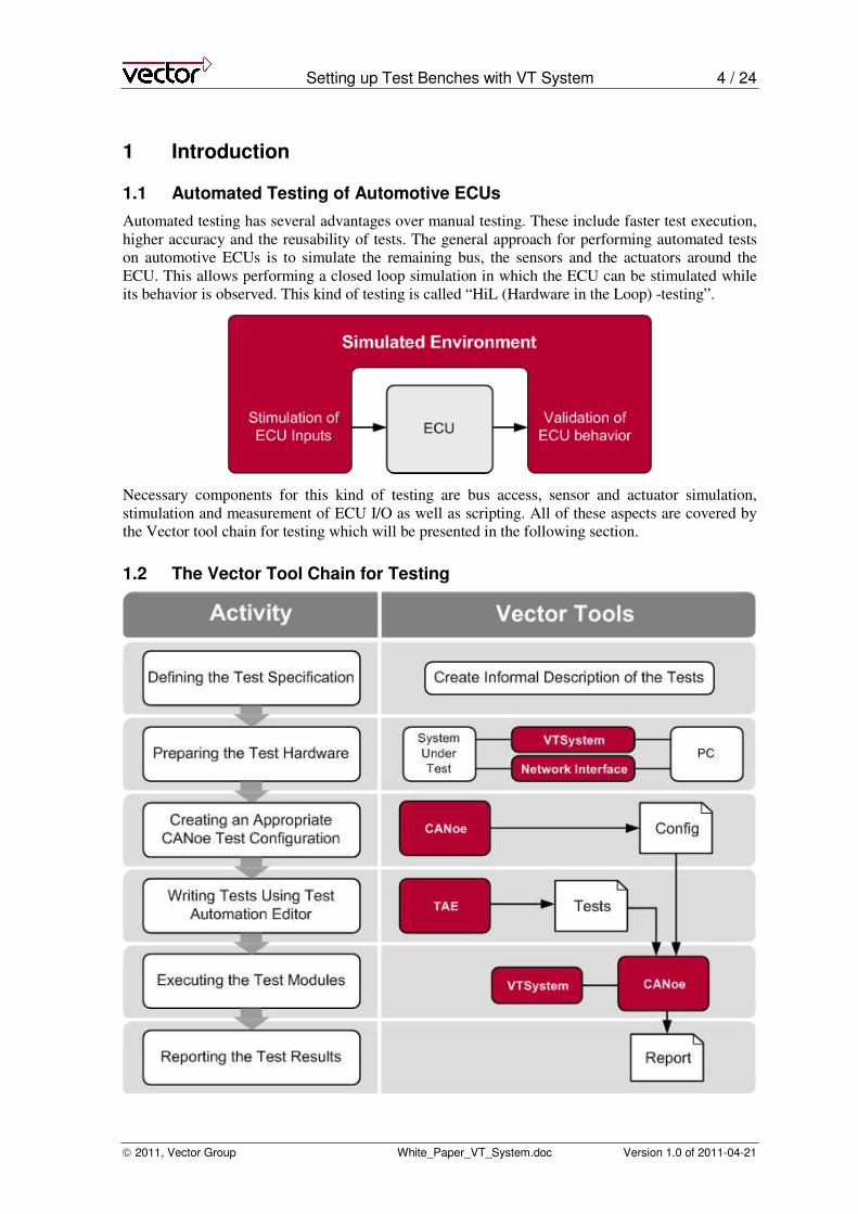
its behavior is observed. This kind of testing is called “HiL (Hardware in the Loop) -testing”.
Necessary components for this kind of testing are bus access, sensor and actuator simulation,
stimulation and measurement of ECU I/O as well as scripting. All of these aspects are covered by
the Vector tool chain for testing which will be presented in the following section.
1.2 The Vector Tool Chain for Testing
Setting up Test Benches with VT System 5 / 24
2011, Vector Group White_Paper_VT_System.doc Version 1.0 of 2011-04-21
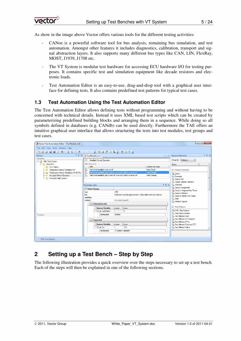
As show in the image above Vector offers various tools for the different testing activities:
- CANoe is a powerful software tool for bus analysis, remaining bus simulation, and test
automation. Amongst other features it includes diagnostics, calibration, transport and sig-
nal abstraction layers. It also supports many different bus types like CAN, LIN, FlexRay,
MOST, J1939, J1708 etc.
- The VT System is modular test hardware for accessing ECU hardware I/O for testing pur-
poses. It contains specific test and simulation equipment like decade resistors and elec-
tronic loads.
- Test Automation Editor is an easy-to-use, drag-and-drop tool with a graphical user inter-
face for defining tests. It also contains predefined test patterns for typical test cases.
1.3 Test Automation Using the Test Automation Editor
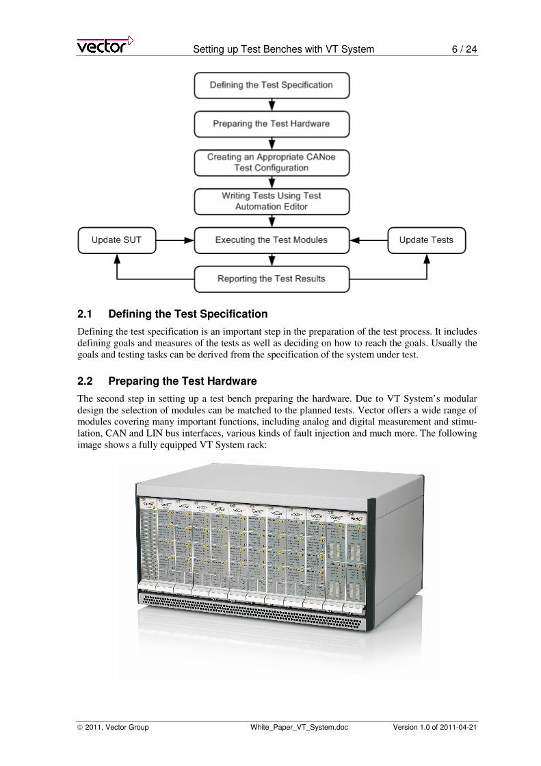
The Test Automation Editor allows defining tests without programming and without having to be
concerned with technical details. Instead it uses XML based test scripts which can be created by
parameterizing predefined building blocks and arranging them in a sequence. While doing so all
symbols defined in databases (e.g. CANdb) can be used directly. Furthermore the TAE offers an
intuitive graphical user interface that allows structuring the tests into test modules, test groups and
test cases.
2 Setting up a Test Bench – Step by Step
The following illustration provides a quick overview over the steps necessary to set up a test bench.
Each of the steps will then be explained in one of the following sections.
Setting up Test Benches with VT System 6 / 24
2011, Vector Group White_Paper_VT_System.doc Version 1.0 of 2011-04-21
2.1 Defining the Test Specification
Defining the test specification is an important step in the preparation of the test process. It includes
defining goals and measures of the tests as well as deciding on how to reach the goals. Usually the
goals and testing tasks can be derived from the specification of the system under test.
2.2 Preparing the Test Hardware
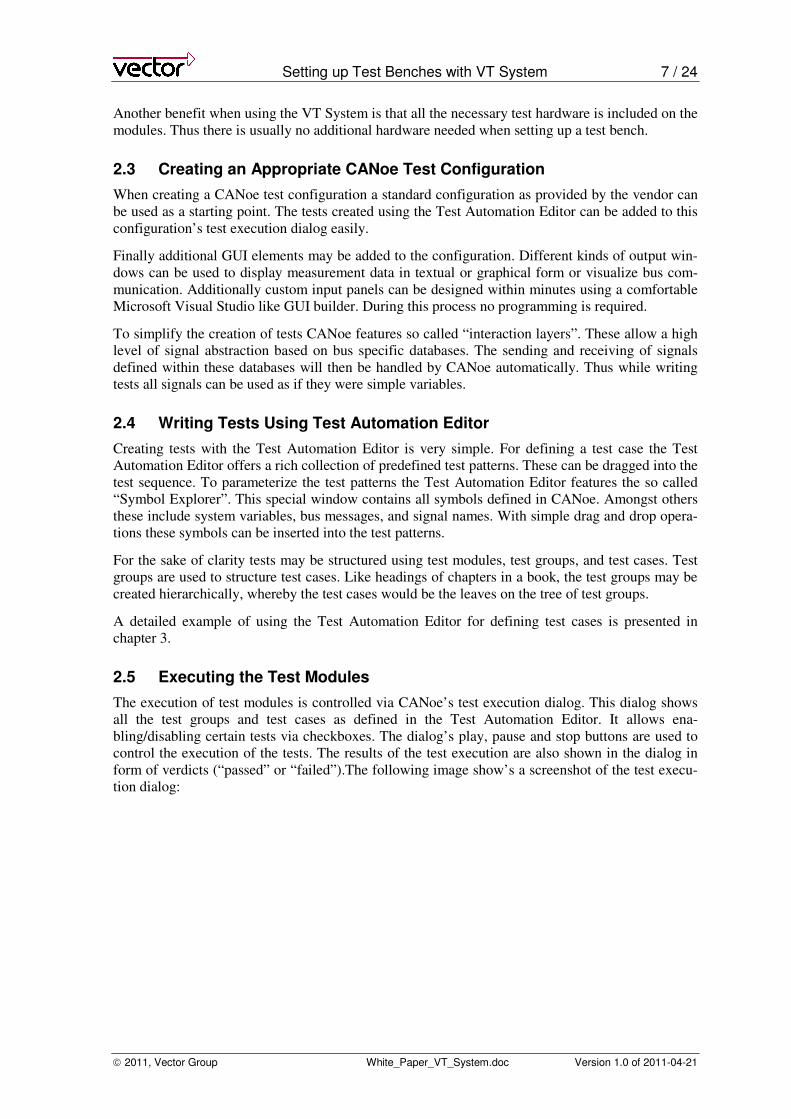
The second step in setting up a test bench preparing the hardware. Due to VT System’s modular
design the selection of modules can be matched to the planned tests. Vector offers a wide range of
modules covering many important functions, including analog and digital measurement and stimu-
lation, CAN and LIN bus interfaces, various kinds of fault injection and much more. The following
image shows a fully equipped VT System rack:
Setting up Test Benches with VT System 7 / 24
2011, Vector Group White_Paper_VT_System.doc Version 1.0 of 2011-04-21
Another benefit when using the VT System is that all the necessary test hardware is included on the
modules. Thus there is usually no additional hardware needed when setting up a test bench.
2.3 Creating an Appropriate CANoe Test Configuration
When creating a CANoe test configuration a standard configuration as provided by the vendor can
be used as a starting point. The tests created using the Test Automation Editor can be added to this
configuration’s test execution dialog easily.
Finally additional GUI elements may be added to the configuration. Different kinds of output win-
dows can be used to display measurement data in textual or graphical form or visualize bus com-
munication. Additionally custom input panels can be designed within minutes using a comfortable
Microsoft Visual Studio like GUI builder. During this process no programming is required.
To simplify the creation of tests CANoe features so called “interaction layers”. These allow a high
level of signal abstraction based on bus specific databases. The sending and receiving of signals
defined within these databases will then be handled by CANoe automatically. Thus while writing
tests all signals can be used as if they were simple variables.
2.4 Writing Tests Using Test Automation Editor
Creating tests with the Test Automation Editor is very simple. For defining a test case the Test
Automation Editor offers a rich collection of predefined test patterns. These can be dragged into the
test sequence. To parameterize the test patterns the Test Automation Editor features the so called
“Symbol Explorer”. This special window contains all symbols defined in CANoe. Amongst others
these include system variables, bus messages, and signal names. With simple drag and drop opera-
tions these symbols can be inserted into the test patterns.
For the sake of clarity tests may be structured using test modules, test groups, and test cases. Test
groups are used to structure test cases. Like headings of chapters in a book, the test groups may be
created hierarchically, whereby the test cases would be the leaves on the tree of test groups.
A detailed example of using the Test Automation Editor for defining test cases is presented in
chapter 3.
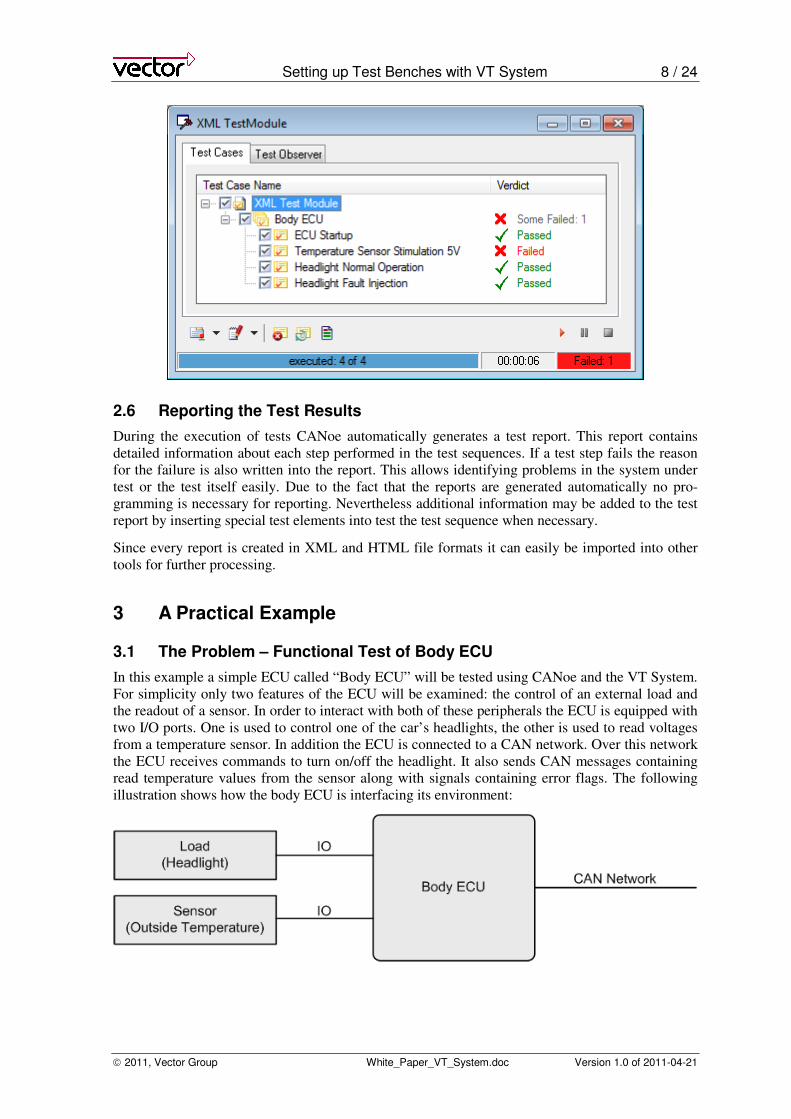
2.5 Executing the Test Modules
The execution of test modules is controlled via CANoe’s test execution dialog. This dialog shows
all the test groups and test cases as defined in the Test Automation Editor. It allows ena-
bling/disabling certain tests via checkboxes. The dialog’s play, pause and stop buttons are used to
control the execution of the tests. The results of the test execution are also shown in the dialog in
form of verdicts (“passed” or “failed”).The following image show’s a screenshot of the test execu-
tion dialog:
Setting up Test Benches with VT System 8 / 24
2011, Vector Group White_Paper_VT_System.doc Version 1.0 of 2011-04-21
2.6 Reporting the Test Results
During the execution of tests CANoe automatically generates a test report. This report contains
detailed information about each step performed in the test sequences. If a test step fails the reason
for the failure is also written into the report. This allows identifying problems in the system under
test or the test itself easily. Due to the fact that the reports are generated automatically no pro-
gramming is necessary for reporting. Nevertheless additional information may be added to the test
report by inserting special test elements into test the test sequence when necessary.
Since every report is created in XML and HTML file formats it can easily be imported into other
tools for further processing.
3 A Practical Example
3.1 The Problem – Functional Test of Body ECU
In this example a simple ECU called “Body ECU” will be tested using CANoe and the VT System.
For simplicity only two features of the ECU will be examined: the control of an external load and
the readout of a sensor. In order to interact with both of these peripherals the ECU is equipped with
two I/O ports. One is used to control one of the car’s headlights, the other is used to read voltages
from a temperature sensor. In addition the ECU is connected to a CAN network. Over this network
the ECU receives commands to turn on/off the headlight. It also sends CAN messages containing
read temperature values from the sensor along with signals containing error flags. The following
illustration shows how the body ECU is interfacing its environment:
Setting up Test Benches with VT System 9 / 24
2011, Vector Group White_Paper_VT_System.doc Version 1.0 of 2011-04-21
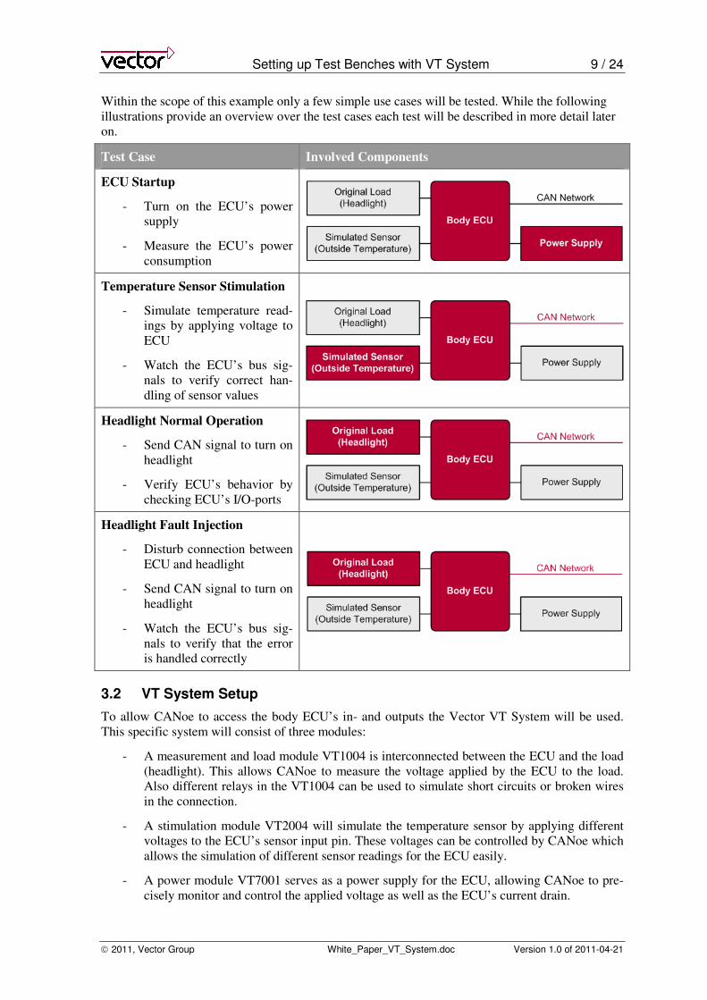
Within the scope of this example only a few simple use cases will be tested. While the following
illustrations provide an overview over the test cases each test will be described in more detail later
on.
Test Case Involved Components
ECU Startup
- Turn on the ECU’s power
supply
- Measure the ECU’s power
consumption
Temperature Sensor Stimulation
- Simulate temperature read-
ings by applying voltage to
ECU
- Watch the ECU’s bus sig-
nals to verify correct han-
dling of sensor values
Headlight Normal Operation
- Send CAN signal to turn on
headlight
- Verify ECU’s behavior by
checking ECU’s I/O-ports
Headlight Fault Injection
- Disturb connection between
ECU and headlight
- Send CAN signal to turn on
headlight
- Watch the ECU’s bus sig-
nals to verify that the error
is handled correctly
3.2 VT System Setup
To allow CANoe to access the body ECU’s in- and outputs the Vector VT System will be used.
This specific system will consist of three modules:
- A measurement and load module VT1004 is interconnected between the ECU and the load
(headlight). This allows CANoe to measure the voltage applied by the ECU to the load.
Also different relays in the VT1004 can be used to simulate short circuits or broken wires
in the connection.
- A stimulation module VT2004 will simulate the temperature sensor by applying different
voltages to the ECU’s sensor input pin. These voltages can be controlled by CANoe which
allows the simulation of different sensor readings for the ECU easily.
- A power module VT7001 serves as a power supply for the ECU, allowing CANoe to pre-
cisely monitor and control the applied voltage as well as the ECU’s current drain.
Setting up Test Benches with VT System 10 / 24
2011, Vector Group White_Paper_VT_System.doc Version 1.0 of 2011-04-21
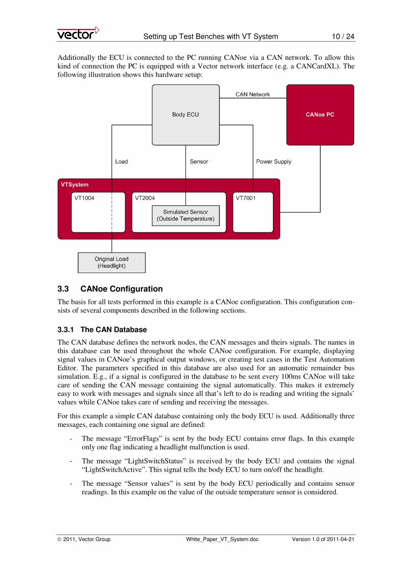
Additionally the ECU is connected to the PC running CANoe via a CAN network. To allow this
kind of connection the PC is equipped with a Vector network interface (e.g. a CANCardXL). The
following illustration shows this hardware setup:
3.3 CANoe Configuration
The basis for all tests performed in this example is a CANoe configuration. This configuration con-
sists of several components described in the following sections.
3.3.1 The CAN Database
The CAN database defines the network nodes, the CAN messages and theirs signals. The names in
this database can be used throughout the whole CANoe configuration. For example, displaying
signal values in CANoe’s graphical output windows, or creating test cases in the Test Automation
Editor. The parameters specified in this database are also used for an automatic remainder bus
simulation. E.g., if a signal is configured in the database to be sent every 100ms CANoe will take
care of sending the CAN message containing the signal automatically. This makes it extremely
easy to work with messages and signals since all that’s left to do is reading and writing the signals’
values while CANoe takes care of sending and receiving the messages.
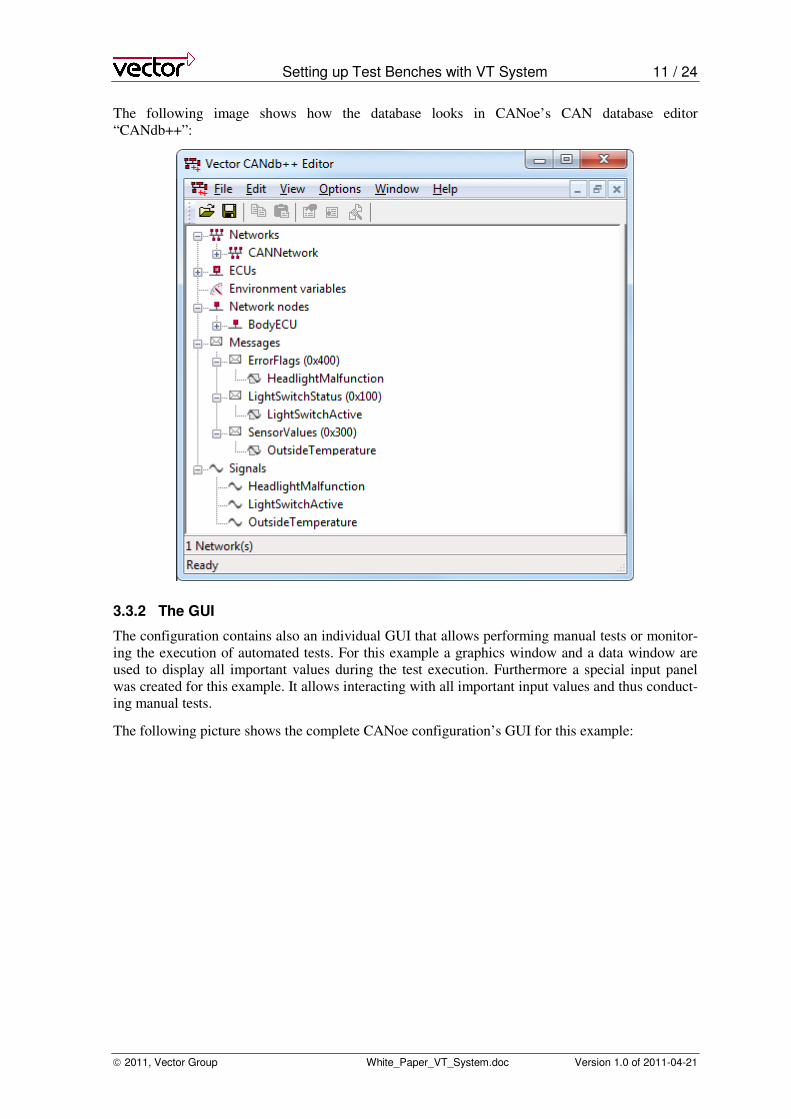
For this example a simple CAN database containing only the body ECU is used. Additionally three
messages, each containing one signal are defined:
- The message “ErrorFlags” is sent by the body ECU contains error flags. In this example
only one flag indicating a headlight malfunction is used.
- The message “LightSwitchStatus” is received by the body ECU and contains the signal
“LightSwitchActive”. This signal tells the body ECU to turn on/off the headlight.
- The message “Sensor values” is sent by the body ECU periodically and contains sensor
readings. In this example on the value of the outside temperature sensor is considered.
Setting up Test Benches with VT System 11 / 24
2011, Vector Group White_Paper_VT_System.doc Version 1.0 of 2011-04-21
The following image shows how the database looks in CANoe’s CAN database editor
“CANdb++”:
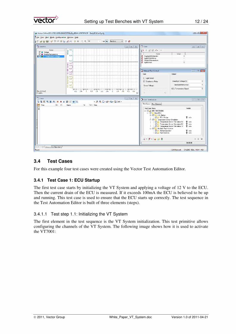
3.3.2 The GUI
The configuration contains also an individual GUI that allows performing manual tests or monitor-
ing the execution of automated tests. For this example a graphics window and a data window are
used to display all important values during the test execution. Furthermore a special input panel
was created for this example. It allows interacting with all important input values and thus conduct-
ing manual tests.
The following picture shows the complete CANoe configuration’s GUI for this example:
Setting up Test Benches with VT System 12 / 24
2011, Vector Group White_Paper_VT_System.doc Version 1.0 of 2011-04-21
3.4 Test Cases
For this example four test cases were created using the Vector Test Automation Editor.
3.4.1 Test Case 1: ECU Startup
The first test case starts by initializing the VT System and applying a voltage of 12 V to the ECU.
Then the current drain of the ECU is measured. If it exceeds 100mA the ECU is believed to be up
and running. This test case is used to ensure that the ECU starts up correctly. The test sequence in
the Test Automation Editor is built of three elements (steps).
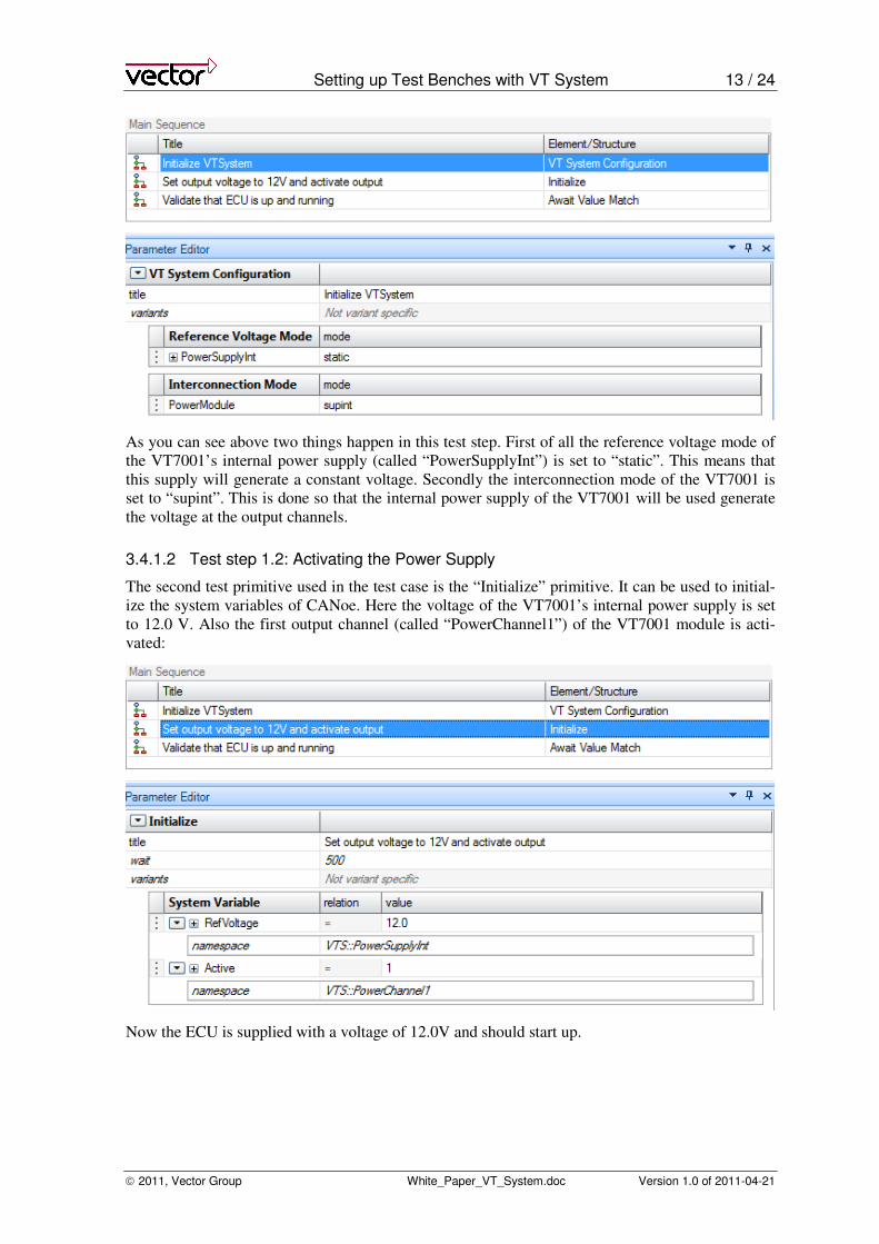
3.4.1.1 Test step 1.1: Initializing the VT System
The first element in the test sequence is the VT System initialization. This test primitive allows
configuring the channels of the VT System. The following image shows how it is used to activate
the VT7001:
Setting up Test Benches with VT System 13 / 24
2011, Vector Group White_Paper_VT_System.doc Version 1.0 of 2011-04-21
As you can see above two things happen in this test step. First of all the reference voltage mode of
the VT7001’s internal power supply (called “PowerSupplyInt”) is set to “static”. This means that
this supply will generate a constant voltage. Secondly the interconnection mode of the VT7001 is
set to “supint”. This is done so that the internal power supply of the VT7001 will be used generate
the voltage at the output channels.
3.4.1.2 Test step 1.2: Activating the Power Supply
The second test primitive used in the test case is the “Initialize” primitive. It can be used to initial-
ize the system variables of CANoe. Here the voltage of the VT7001’s internal power supply is set
to 12.0 V. Also the first output channel (called “PowerChannel1”) of the VT7001 module is acti-
vated:
Now the ECU is supplied with a voltage of 12.0V and should start up.
Setting up Test Benches with VT System 14 / 24
2011, Vector Group White_Paper_VT_System.doc Version 1.0 of 2011-04-21
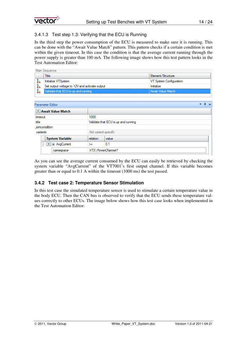
3.4.1.3 Test step 1.3: Verifying that the ECU is Running
In the third step the power consumption of the ECU is measured to make sure it is running. This
can be done with the “Await Value Match” pattern. This pattern checks if a certain condition is met
within the given timeout. In this case the condition is that the average current running through the
power supply is greater than 100 mA. The following image shows how this test pattern looks in the
Test Automation Editor:
As you can see the average current consumed by the ECU can easily be retrieved by checking the
system variable “AvgCurrent” of the VT7001’s first output channel. If this variable becomes
greater than or equal to 0.1 A within the timeout (1000 ms) the test passed.
3.4.2 Test case 2: Temperature Sensor Stimulation
In this test case the simulated temperature sensor is used to stimulate a certain temperature value in
the body ECU. Then the CAN bus is observed to verify that the ECU sends these temperature val-
ues correctly to other ECUs. The image below shows how this test case looks when implemented in
the Test Automation Editor:
Setting up Test Benches with VT System 15 / 24
2011, Vector Group White_Paper_VT_System.doc Version 1.0 of 2011-04-21
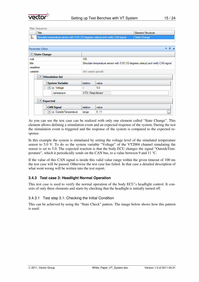
As you can see the test case can be realized with only one element called “State Change”. This
element allows defining a stimulation event and an expected response of the system. During the test
the stimulation event is triggered and the response of the system is compared to the expected re-
sponse.
In this example the system is stimulated by setting the voltage level of the simulated temperature
sensor to 5.0 V. To do so the system variable “Voltage” of the VT2004 channel simulating the
sensor is set to 5.0. The expected reaction is that the body ECU changes the signal “OutsideTem-
perature”, which it periodically sends on the CAN bus, to a value between 9 and 11 °C.
If the value of this CAN signal is inside this valid value range within the given timeout of 100 ms
the test case will be passed. Otherwise the test case has failed. In that case a detailed description of
what went wrong will be written into the test report.
3.4.3 Test case 3: Headlight Normal Operation
This test case is used to verify the normal operation of the body ECU’s headlight control. It con-
sists of only three elements and starts by checking that the headlight is initially turned off.
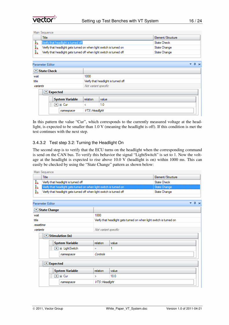
3.4.3.1 Test step 3.1: Checking the Initial Condition
This can be achieved by using the “State Check” pattern. The image below shows how this pattern
is used:
Setting up Test Benches with VT System 16 / 24
2011, Vector Group White_Paper_VT_System.doc Version 1.0 of 2011-04-21
In this pattern the value “Cur”, which corresponds to the currently measured voltage at the head-
light, is expected to be smaller than 1.0 V (meaning the headlight is off). If this condition is met the
test continues with the next step.
3.4.3.2 Test step 3.2: Turning the Headlight On
The second step is to verify that the ECU turns on the headlight when the corresponding command
is send on the CAN bus. To verify this behavior the signal “LightSwitch” is set to 1. Now the volt-
age at the headlight is expected to rise above 10.0 V (headlight is on) within 1000 ms. This can
easily be checked by using the “State Change” pattern as shown below:
Setting up Test Benches with VT System 17 / 24
2011, Vector Group White_Paper_VT_System.doc Version 1.0 of 2011-04-21
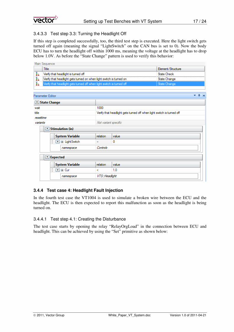
3.4.3.3 Test step 3.3: Turning the Headlight Off
If this step is completed successfully, too, the third test step is executed. Here the light switch gets
turned off again (meaning the signal “LightSwitch” on the CAN bus is set to 0). Now the body
ECU has to turn the headlight off within 1000 ms, meaning the voltage at the headlight has to drop
below 1.0V. As before the “State Change” pattern is used to verify this behavior:
3.4.4 Test case 4: Headlight Fault Injection
In the fourth test case the VT1004 is used to simulate a broken wire between the ECU and the
headlight. The ECU is then expected to report this malfunction as soon as the headlight is being
turned on.
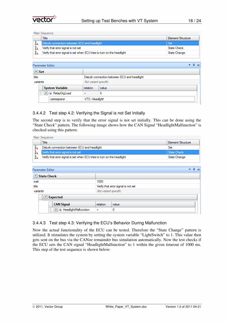
3.4.4.1 Test step 4.1: Creating the Disturbance
The test case starts by opening the relay “RelayOrgLoad” in the connection between ECU and
headlight. This can be achieved by using the “Set” primitive as shown below:
Setting up Test Benches with VT System 18 / 24
2011, Vector Group White_Paper_VT_System.doc Version 1.0 of 2011-04-21
3.4.4.2 Test step 4.2: Verifying the Signal is not Set Initially
The second step is to verify that the error signal is not set initially. This can be done using the
“State Check” pattern. The following image shows how the CAN Signal “HeadlightMalfunction” is
checked using this pattern:
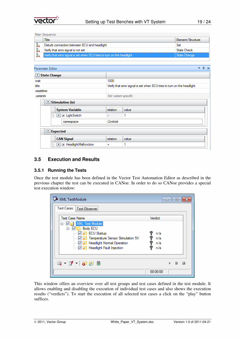
3.4.4.3 Test step 4.3: Verifying the ECU’s Behavior During Malfunction
Now the actual functionality of the ECU can be tested. Therefore the “State Change” pattern is
utilized. It stimulates the system by setting the system variable “LightSwitch” to 1. This value then
gets sent on the bus via the CANoe remainder bus simulation automatically. Now the test checks if
the ECU sets the CAN signal “HeadlightMalfunction” to 1 within the given timeout of 1000 ms.
This step of the test sequence is shown below:
Setting up Test Benches with VT System 19 / 24
2011, Vector Group White_Paper_VT_System.doc Version 1.0 of 2011-04-21
3.5 Execution and Results
3.5.1 Running the Tests
Once the test module has been defined in the Vector Test Automation Editor as described in the
previous chapter the test can be executed in CANoe. In order to do so CANoe provides a special
test execution window:
This window offers an overview over all test groups and test cases defined in the test module. It
allows enabling and disabling the execution of individual test cases and also shows the execution
results (“verdicts”). To start the execution of all selected test cases a click on the “play” button
suffices.
Setting up Test Benches with VT System 20 / 24
2011, Vector Group White_Paper_VT_System.doc Version 1.0 of 2011-04-21
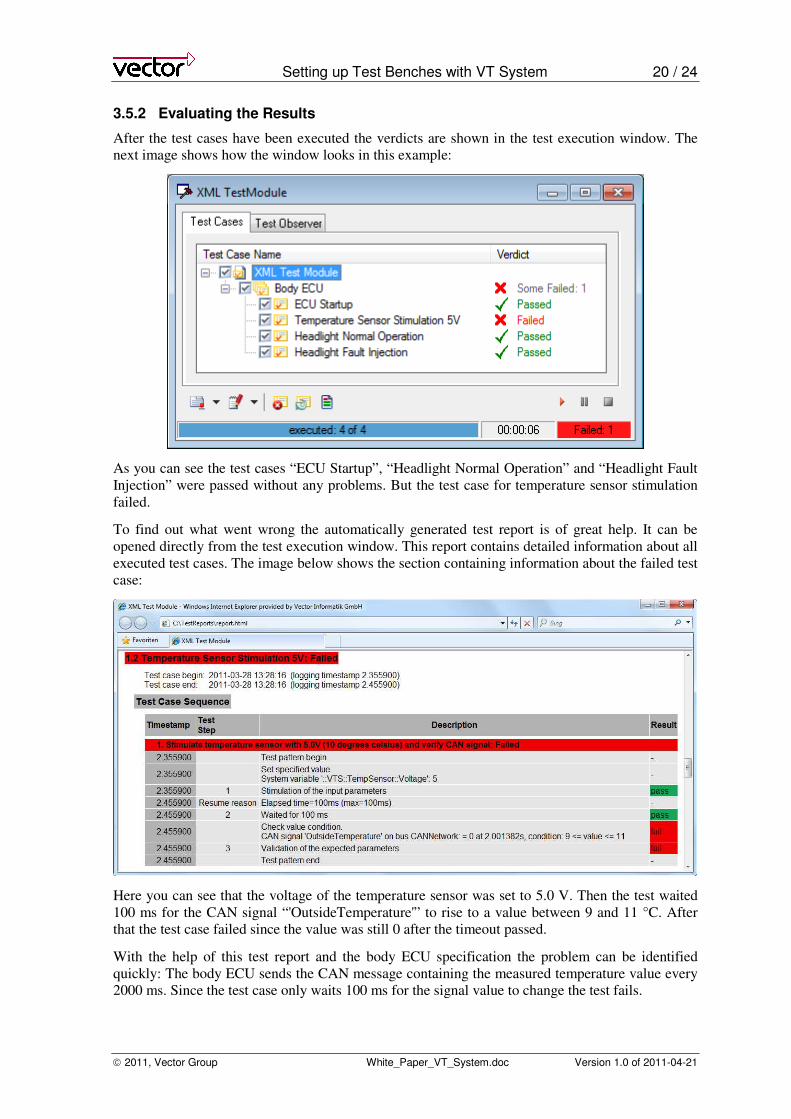
3.5.2 Evaluating the Results
After the test cases have been executed the verdicts are shown in the test execution window. The
next image shows how the window looks in this example:
As you can see the test cases “ECU Startup”, “Headlight Normal Operation” and “Headlight Fault
Injection” were passed without any problems. But the test case for temperature sensor stimulation
failed.
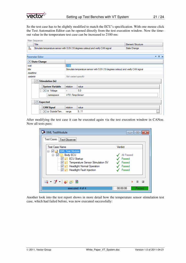
To find out what went wrong the automatically generated test report is of great help. It can be
opened directly from the test execution window. This report contains detailed information about all
executed test cases. The image below shows the section containing information about the failed test
case:
Here you can see that the voltage of the temperature sensor was set to 5.0 V. Then the test waited
100 ms for the CAN signal “'OutsideTemperature'” to rise to a value between 9 and 11 °C. After
that the test case failed since the value was still 0 after the timeout passed.
With the help of this test report and the body ECU specification the problem can be identified
quickly: The body ECU sends the CAN message containing the measured temperature value every
2000 ms. Since the test case only waits 100 ms for the signal value to change the test fails.
Setting up Test Benches with VT System 21 / 24
2011, Vector Group White_Paper_VT_System.doc Version 1.0 of 2011-04-21
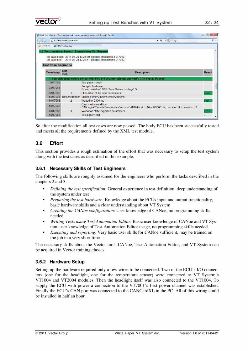
So the test case has to be slightly modified to match the ECU’s specification. With one mouse click
the Test Automation Editor can be opened directly from the test execution window. Now the time-
out value in the temperature test case can be increased to 2100 ms:
After modifying the test case it can be executed again via the test execution window in CANoe.
Now all tests pass:
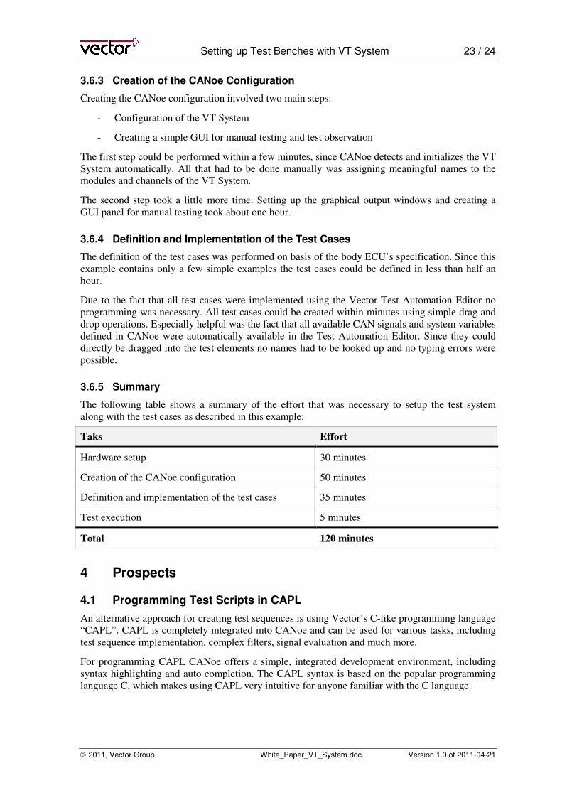
Another look into the test report shows in more detail how the temperature sensor stimulation test
case, which had failed before, was now executed successfully:
Setting up Test Benches with VT System 22 / 24
2011, Vector Group White_Paper_VT_System.doc Version 1.0 of 2011-04-21
So after the modification all test cases are now passed. The body ECU has been successfully tested
and meets all the requirements defined by the XML test module.
3.6 Effort
This section provides a rough estimation of the effort that was necessary to setup the test system
along with the test cases as described in this example.
3.6.1 Necessary Skills of Test Engineers
The following skills are roughly assumed for the engineers who perform the tasks described in the
chapters 2 and 3:
• Defining the test specification: General experience in test definition, deep understanding of
the system under test
• Preparing the test hardware: Knowledge about the ECUs input and output functionality,
basic hardware skills and a clear understanding about VT System
• Creating the CANoe configuration: User knowledge of CANoe, no programming skills
needed
• Writing Tests using Test Automation Editor: Basic user knowledge of CANoe and VT Sys-
tem, user knowledge of Test Automation Editor usage, no programming skills needed
• Executing and reporting: Very basic user skills for CANoe sufficient, may be trained on
the job in a very short time
The necessary skills about the Vector tools CANoe, Test Automation Editor, and VT System can
be acquired in Vector training classes.
3.6.2 Hardware Setup
Setting up the hardware required only a few wires to be connected. Two of the ECU’s I/O connec-
tors (one for the headlight, one for the temperature sensor) were connected to VT System’s
VT1004 and VT2004 modules. Then the headlight itself was also connected to the VT1004. To
supply the ECU with power a connection to the VT7001’s first power channel was established.
Finally the ECU’s CAN port was connected to the CANCardXL in the PC. All of this wiring could
be installed in half an hour.
Setting up Test Benches with VT System 23 / 24
2011, Vector Group White_Paper_VT_System.doc Version 1.0 of 2011-04-21
3.6.3 Creation of the CANoe Configuration
Creating the CANoe configuration involved two main steps:
- Configuration of the VT System
- Creating a simple GUI for manual testing and test observation
The first step could be performed within a few minutes, since CANoe detects and initializes the VT
System automatically. All that had to be done manually was assigning meaningful names to the
modules and channels of the VT System.
The second step took a little more time. Setting up the graphical output windows and creating a
GUI panel for manual testing took about one hour.
3.6.4 Definition and Implementation of the Test Cases
The definition of the test cases was performed on basis of the body ECU’s specification. Since this
example contains only a few simple examples the test cases could be defined in less than half an
hour.
Due to the fact that all test cases were implemented using the Vector Test Automation Editor no
programming was necessary. All test cases could be created within minutes using simple drag and
drop operations. Especially helpful was the fact that all available CAN signals and system variables
defined in CANoe were automatically available in the Test Automation Editor. Since they could
directly be dragged into the test elements no names had to be looked up and no typing errors were
possible.
3.6.5 Summary
The following table shows a summary of the effort that was necessary to setup the test system
along with the test cases as described in this example:
Taks Effort
Hardware setup 30 minutes
Creation of the CANoe configuration 50 minutes
Definition and implementation of the test cases 35 minutes
Test execution 5 minutes
Total 120 minutes
4 Prospects
4.1 Programming Test Scripts in CAPL
An alternative approach for creating test sequences is using Vector’s C-like programming language
“CAPL”. CAPL is completely integrated into CANoe and can be used for various tasks, including
test sequence implementation, complex filters, signal evaluation and much more.
For programming CAPL CANoe offers a simple, integrated development environment, including
syntax highlighting and auto completion. The CAPL syntax is based on the popular programming
language C, which makes using CAPL very intuitive for anyone familiar with the C language.
Setting up Test Benches with VT System 24 / 24
2011, Vector Group White_Paper_VT_System.doc Version 1.0 of 2011-04-21
4.1.1 A small example
The following image shows how one of the test cases from the Body ECU example looks when
implemented in CAPL:
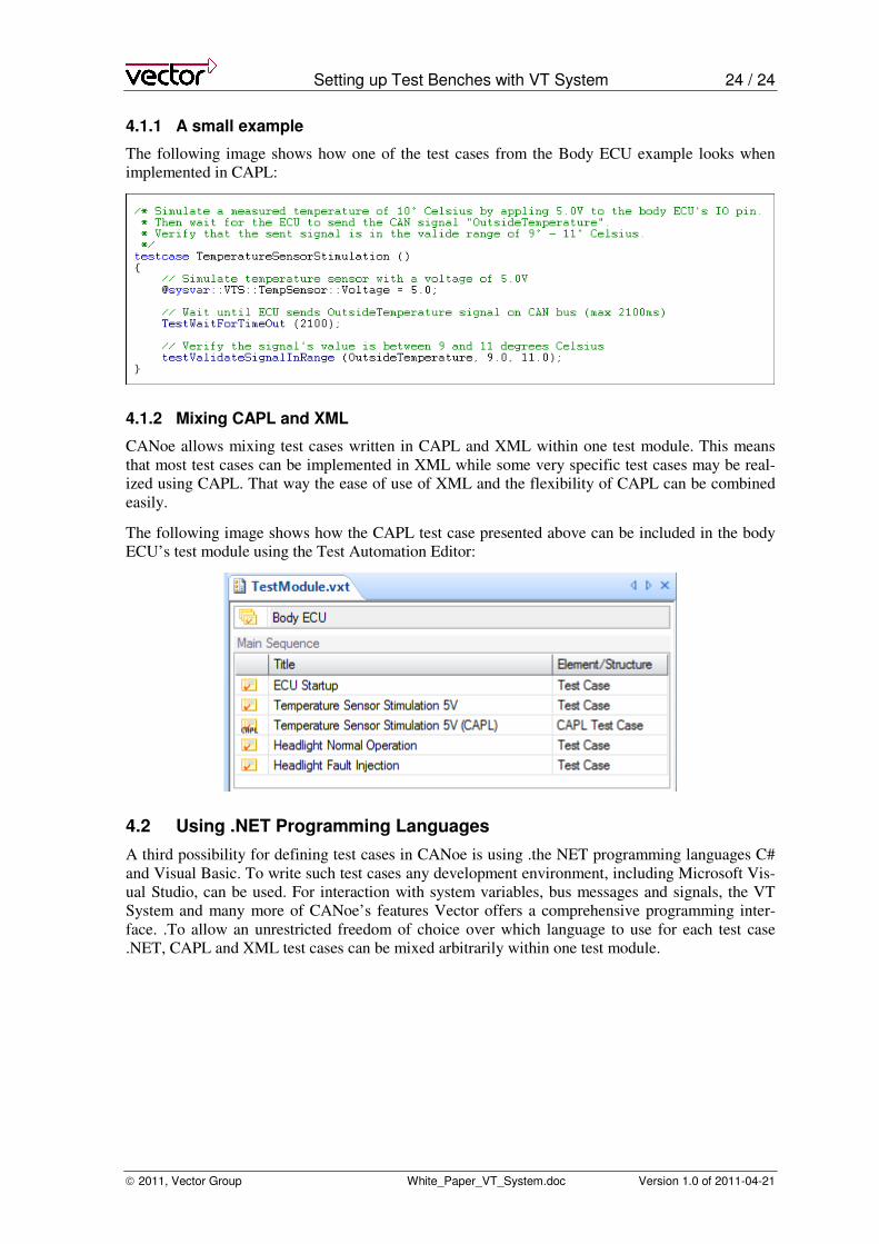
4.1.2 Mixing CAPL and XML
CANoe allows mixing test cases written in CAPL and XML within one test module. This means
that most test cases can be implemented in XML while some very specific test cases may be real-
ized using CAPL. That way the ease of use of XML and the flexibility of CAPL can be combined
easily.
The following image shows how the CAPL test case presented above can be included in the body
ECU’s test module using the Test Automation Editor:
4.2 Using .NET Programming Languages
A third possibility for defining test cases in CANoe is using .the NET programming languages C#
and Visual Basic. To write such test cases any development environment, including Microsoft Vis-
ual Studio, can be used. For interaction with system variables, bus messages and signals, the VT
System and many more of CANoe’s features Vector offers a comprehensive programming inter-
face. .To allow an unrestricted freedom of choice over which language to use for each test case
.NET, CAPL and XML test cases can be mixed arbitrarily within one test module.

White Paper Title
© Vector Informatik 5
Get more Information!
Visit our Website for:
> News
> Products
> Demo Software
> Support
> Training Classes
> Addresses
www.vector.com