Embed Size (px)
Citation preview
BIAMP SYSTEMS TECHNICAL SUPPORT GROUP www.biamp.com • Page 1 of 11
BIAMPTesiraNetworkingGuide
Creating a CobraNet VLAN on the Netgear GS724T-AVB.
Introduction:
There are many possible reasons to separate CobraNet traffic from other network traffic in
your audio system and at Biamp we recommend always keeping CobraNet traffic isolated
from other traffic as a matter of best practice.
This can be accomplished by using a separate network switch for CobraNet but it is also a
simple matter to create a Virtual LAN, or VLAN, on the Netgear GS724T-AVB.
A VLAN can be thought of as a separate Broadcast Domain within a single network (a single
switch or many switches). Isolating CobraNet devices on a separate VLAN means that
broadcast and multicast traffic from other systems will not reach and affect the CobraNet
devices and, similarly, CobraNet traffic will be kept away from non-CobraNet devices.
This document details the steps for creating a CobraNet VLAN in the Netgear GS724T-AVB
switch but the process should be similar on most modern, managed switches.
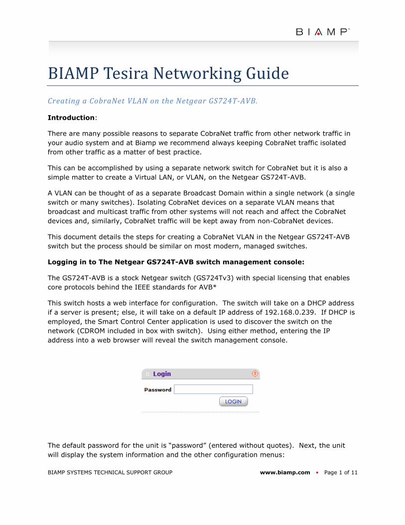
Logging in to The Netgear GS724T-AVB switch management console:
The GS724T-AVB is a stock Netgear switch (GS724Tv3) with special licensing that enables
core protocols behind the IEEE standards for AVB*
This switch hosts a web interface for configuration. The switch will take on a DHCP address
if a server is present; else, it will take on a default IP address of 192.168.0.239. If DHCP is
employed, the Smart Control Center application is used to discover the switch on the
network (CDROM included in box with switch). Using either method, entering the IP
address into a web browser will reveal the switch management console.
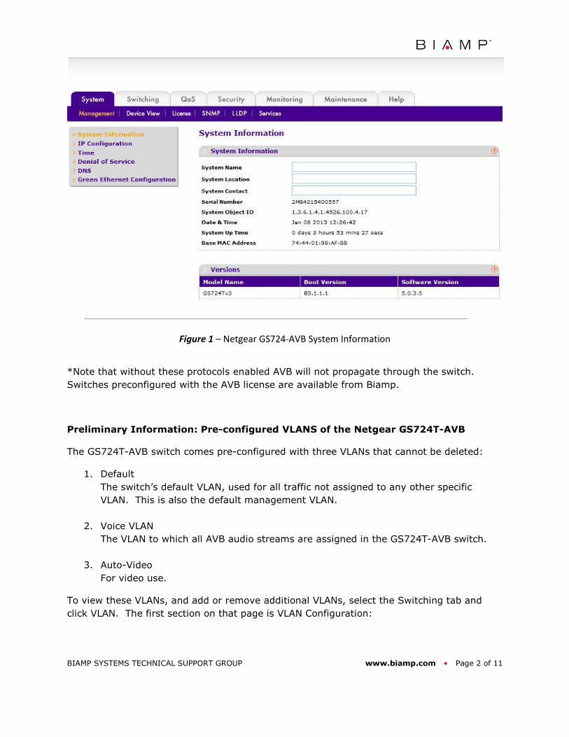
The default password for the unit is “password” (entered without quotes). Next, the unit
will display the system information and the other configuration menus:
BIAMP SYSTEMS TECHNICAL SUPPORT GROUP www.biamp.com • Page 2 of 11
Figure 1 – Netgear GS724-AVB System Information
*Note that without these protocols enabled AVB will not propagate through the switch.
Switches preconfigured with the AVB license are available from Biamp.
Preliminary Information: Pre-configured VLANS of the Netgear GS724T-AVB
The GS724T-AVB switch comes pre-configured with three VLANs that cannot be deleted:
1. Default
The switch’s default VLAN, used for all traffic not assigned to any other specific
VLAN. This is also the default management VLAN.
2. Voice VLAN
The VLAN to which all AVB audio streams are assigned in the GS724T-AVB switch.
3. Auto-Video
For video use.
To view these VLANs, and add or remove additional VLANs, select the Switching tab and
click VLAN. The first section on that page is VLAN Configuration:
BIAMP SYSTEMS TECHNICAL SUPPORT GROUP www.biamp.com • Page 3 of 11
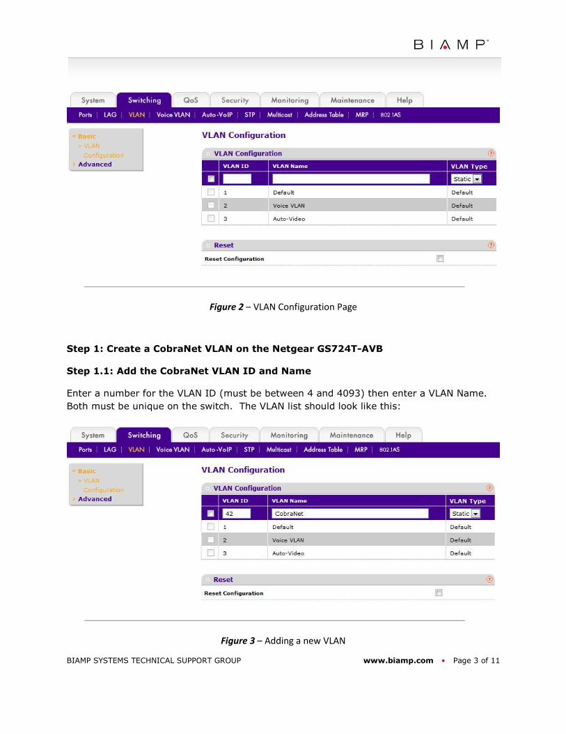
Figure 2 – VLAN Configuration Page
Step 1: Create a CobraNet VLAN on the Netgear GS724T-AVB
Step 1.1: Add the CobraNet VLAN ID and Name
Enter a number for the VLAN ID (must be between 4 and 4093) then enter a VLAN Name.
Both must be unique on the switch. The VLAN list should look like this:
Figure 3 – Adding a new VLAN
BIAMP SYSTEMS TECHNICAL SUPPORT GROUP www.biamp.com • Page 4 of 11
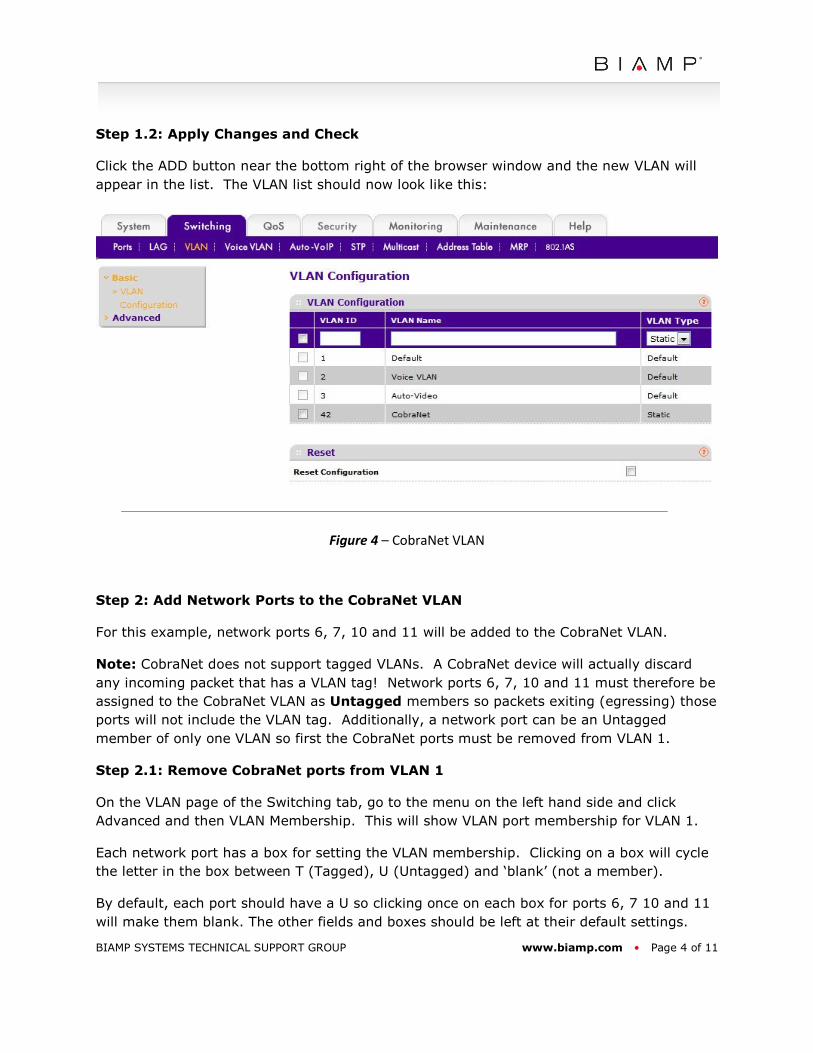
Step 1.2: Apply Changes and Check
Click the ADD button near the bottom right of the browser window and the new VLAN will
appear in the list. The VLAN list should now look like this:
Figure 4 – CobraNet VLAN
Step 2: Add Network Ports to the CobraNet VLAN
For this example, network ports 6, 7, 10 and 11 will be added to the CobraNet VLAN.
Note: CobraNet does not support tagged VLANs. A CobraNet device will actually discard
any incoming packet that has a VLAN tag! Network ports 6, 7, 10 and 11 must therefore be
assigned to the CobraNet VLAN as Untagged members so packets exiting (egressing) those
ports will not include the VLAN tag. Additionally, a network port can be an Untagged
member of only one VLAN so first the CobraNet ports must be removed from VLAN 1.
Step 2.1: Remove CobraNet ports from VLAN 1
On the VLAN page of the Switching tab, go to the menu on the left hand side and click
Advanced and then VLAN Membership. This will show VLAN port membership for VLAN 1.
Each network port has a box for setting the VLAN membership. Clicking on a box will cycle
the letter in the box between T (Tagged), U (Untagged) and ‘blank’ (not a member).
By default, each port should have a U so clicking once on each box for ports 6, 7 10 and 11
will make them blank. The other fields and boxes should be left at their default settings.
BIAMP SYSTEMS TECHNICAL SUPPORT GROUP www.biamp.com • Page 5 of 11
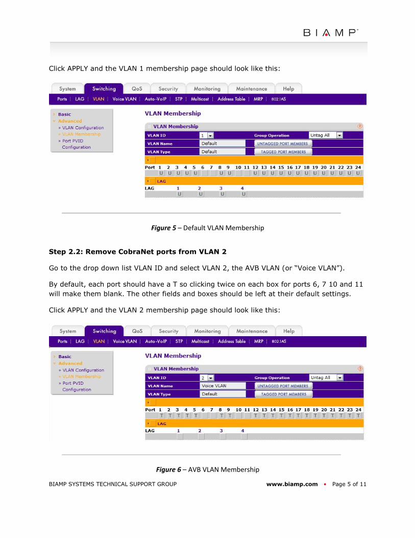
Click APPLY and the VLAN 1 membership page should look like this:
Figure 5 – Default VLAN Membership
Step 2.2: Remove CobraNet ports from VLAN 2
Go to the drop down list VLAN ID and select VLAN 2, the AVB VLAN (or “Voice VLAN”).
By default, each port should have a T so clicking twice on each box for ports 6, 7 10 and 11
will make them blank. The other fields and boxes should be left at their default settings.
Click APPLY and the VLAN 2 membership page should look like this:
Figure 6 – AVB VLAN Membership
BIAMP SYSTEMS TECHNICAL SUPPORT GROUP www.biamp.com • Page 6 of 11
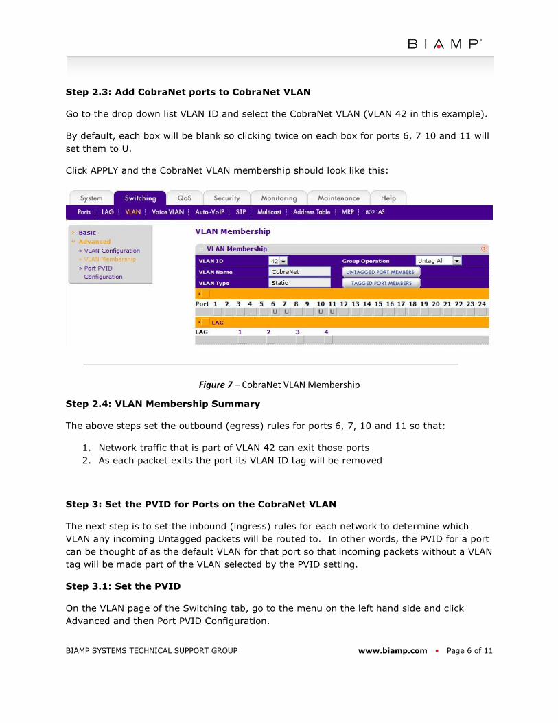
Step 2.3: Add CobraNet ports to CobraNet VLAN
Go to the drop down list VLAN ID and select the CobraNet VLAN (VLAN 42 in this example).
By default, each box will be blank so clicking twice on each box for ports 6, 7 10 and 11 will
set them to U.
Click APPLY and the CobraNet VLAN membership should look like this:
Figure 7 – CobraNet VLAN Membership
Step 2.4: VLAN Membership Summary
The above steps set the outbound (egress) rules for ports 6, 7, 10 and 11 so that:
1. Network traffic that is part of VLAN 42 can exit those ports
2. As each packet exits the port its VLAN ID tag will be removed
Step 3: Set the PVID for Ports on the CobraNet VLAN
The next step is to set the inbound (ingress) rules for each network to determine which
VLAN any incoming Untagged packets will be routed to. In other words, the PVID for a port
can be thought of as the default VLAN for that port so that incoming packets without a VLAN
tag will be made part of the VLAN selected by the PVID setting.
Step 3.1: Set the PVID
On the VLAN page of the Switching tab, go to the menu on the left hand side and click
Advanced and then Port PVID Configuration.
BIAMP SYSTEMS TECHNICAL SUPPORT GROUP www.biamp.com • Page 7 of 11
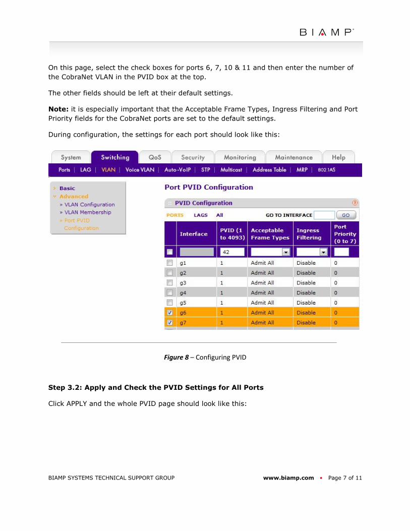
On this page, select the check boxes for ports 6, 7, 10 & 11 and then enter the number of
the CobraNet VLAN in the PVID box at the top.
The other fields should be left at their default settings.
Note: it is especially important that the Acceptable Frame Types, Ingress Filtering and Port
Priority fields for the CobraNet ports are set to the default settings.
During configuration, the settings for each port should look like this:
Figure 8 – Configuring PVID
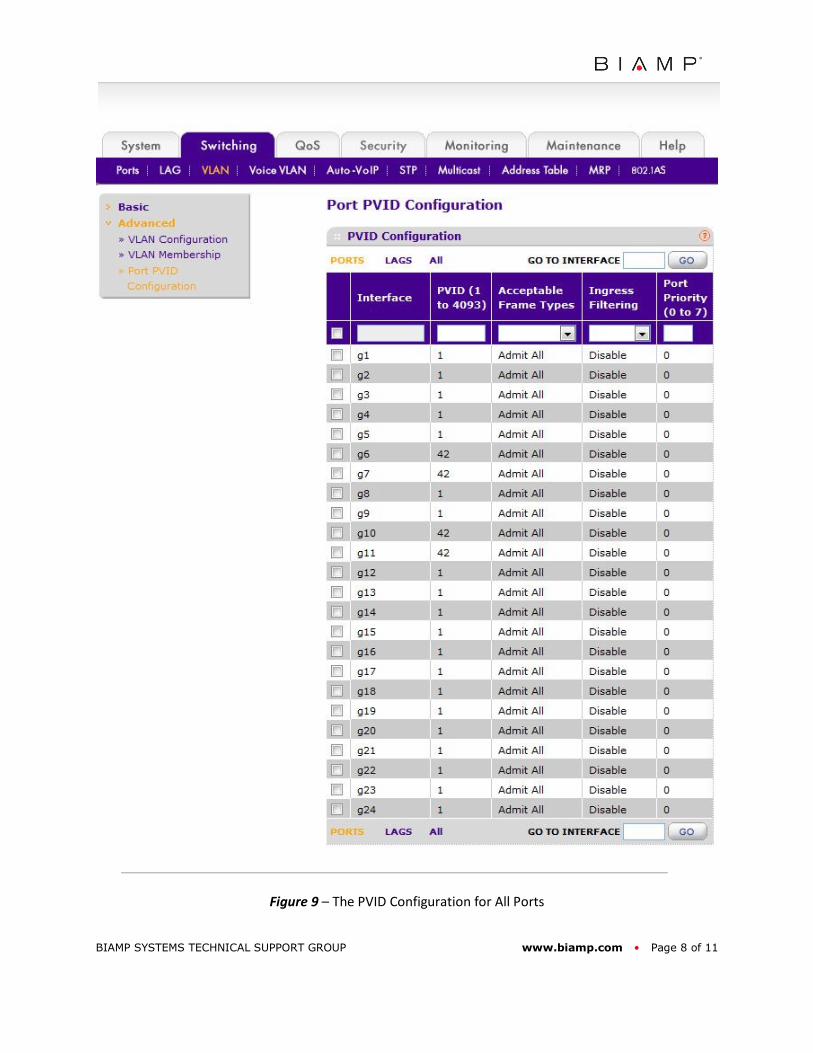
Step 3.2: Apply and Check the PVID Settings for All Ports
Click APPLY and the whole PVID page should look like this:
BIAMP SYSTEMS TECHNICAL SUPPORT GROUP www.biamp.com • Page 8 of 11
Figure 9 – The PVID Configuration for All Ports
BIAMP SYSTEMS TECHNICAL SUPPORT GROUP www.biamp.com • Page 9 of 11
Step 3.3: Port PVID Configuration Summary
The above steps set the inbound (ingress) rules for ports 6, 7, 10 and 11 so that:
1. Any incoming untagged packets will be made part of VLAN 42.
Step 4: Summary
Ports 6, 7, 10 and 11 have now been configured so that:
1. Incoming untagged packets will be made part of VLAN 42 inside the switch, then
2. Be sent only to other ports that are also members of VLAN 42, then
3. Exit those ports without a VLAN ID tag
The above steps are all that is required to create a working CobraNet VLAN on a single
Netgear GS724T-AVB switch. For other things to consider, see below.
ADVANCED TOPICS
Multiple Switch Networks
To expand the size of a network, to have more ports or devices in multiple locations, it is
possible to connect two or more switches together and extend the VLAN across them.
There are two steps to this process:
1. Configure the CobraNet VLAN and CobraNet ports on every switch, as shown above.
2. Configure Uplinks port to connect the switches.
Note: only one link between two switches is allowed unless additional settings are used.
Multiple Switches Step 1: Configure All Netgear GS724T-AVB Switches
First configure the CobraNet VLAN on each switch. Take care to set the CobraNet VLAN
number as exactly the same number on every switch as this is necessary for multi-switch
operation of the VLAN. The VLAN names should be identical simply as good practice.
Multiple Switches Step 2: Configure Uplink Ports on Each Switch
Ports used to connect one switch to another are commonly called Uplinks. Uplinks are
typically the highest numbered ports on a switch, which is why ports 23 and 24 of the
Netgear GS724T-AVB can be fitted with optional fiber modules.
BIAMP SYSTEMS TECHNICAL SUPPORT GROUP www.biamp.com • Page 10 of 11
For uplink ports only the port membership must be configured. Remember that packets
transmitted from a CobraNet device are tagged with the CobraNet VLAN ID as they enter a
switch. This means they can now be moved around the network as Tagged packets until
they are routed to their destination – another CobraNet device.
It is important that the uplink port PVID is left at the default setting of 1 because the uplink
will be used to route traffic of different VLANs, including the default management VLAN.
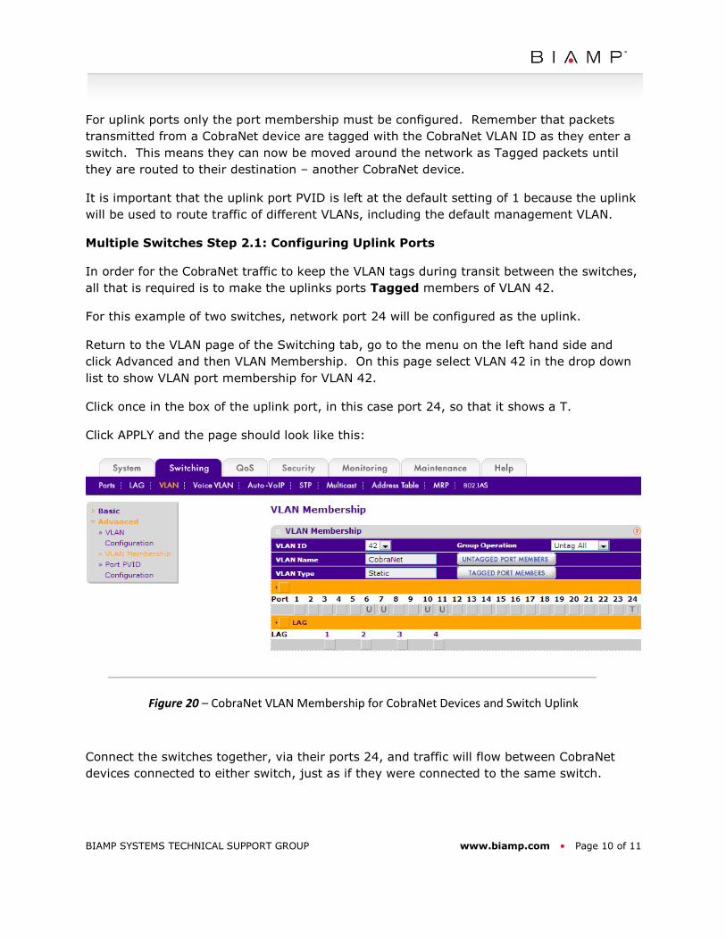
Multiple Switches Step 2.1: Configuring Uplink Ports
In order for the CobraNet traffic to keep the VLAN tags during transit between the switches,
all that is required is to make the uplinks ports Tagged members of VLAN 42.
For this example of two switches, network port 24 will be configured as the uplink.
Return to the VLAN page of the Switching tab, go to the menu on the left hand side and
click Advanced and then VLAN Membership. On this page select VLAN 42 in the drop down
list to show VLAN port membership for VLAN 42.
Click once in the box of the uplink port, in this case port 24, so that it shows a T.
Click APPLY and the page should look like this:
Figure 20 – CobraNet VLAN Membership for CobraNet Devices and Switch Uplink
Connect the switches together, via their ports 24, and traffic will flow between CobraNet
devices connected to either switch, just as if they were connected to the same switch.
BIAMP SYSTEMS TECHNICAL SUPPORT GROUP www.biamp.com • Page 11 of 11
Network Topology
Simple Topology:
3 or more switches can be connected in daisy-chain by configuring ports 23 and 24 as
uplinks for the switches in the middle of the chain. The switches at each end need only one
port configured as an uplink.
Complex Topology:
For complex network topologies, such as daisy-chains with multiple links (for redundancy or
higher bandwidth between switches) or network loops (for redundant cable routing)
additional settings are required that are beyond the scope of this tech note.
CobraNet Network Administration
Note that the devices on the CobraNet VLAN will no longer be accessible from a PC that is
connected to the switch via a port with the default settings. To connect to the CobraNet
devices using a PC, for example to update firmware, it will be necessary to temporarily
configure an additional port on the switch with the same settings.
If this application note did not answer your questions on the topic of “Creating a CobraNet VLAN on the Netgear
GS724T-AVB”, please contact Biamp Technical Support Group by phone at + 1 503 641 7287 or by email at